53
33455830 Rev. 1.1 Instruction Manual PL-583 April 2001 SMARTLINX INTERFACE MODULE FOR DEVICE NET SMARTLINX INTERFACE MODULE R
| Date post: | 26-Jul-2018 |
| Category: |
Documents |
| Upload: | nguyencong |
| View: | 231 times |
| Download: | 0 times |
33455830
Rev. 1.1
Instruction Manual PL-583 April 2001
SM
AR
TL
INX
INT
ER
FA
CE
MO
DU
LE
FOR DEVICE NET
SMARTLINX INTERFACE MODULE
R
© Siemens Milltronics Process Instruments Inc. 2001
Safety Guidelines
Warning notices must be observed to ensure personal safety as well as that of others, and toprotect the product and the connected equipment. These warning notices are accompaniedby a clarification of the level of caution to be observed.
Qualified Personnel
This device/system may only be set up and operated in conjunction with this manual.Qualified personnel are only authorized to install and operate this equipment in accordancewith established safety practices and standards.
Warning: This product can only function properly and safely if it is correctly transported,stored, installed, set up, operated, and maintained.
Note: Always use product in accordance with specifications.
Copyright Siemens Milltronics ProcessInstruments Inc. 2000. All Rights Reserved
Disclaimer of Liability
This document is available in bound version and inelectronic version. We encourage users topurchase authorized bound manuals, or to viewelectronic versions as designed and authored bySiemens Milltronics Process Instruments Inc.Siemens Milltronics Process Instruments Inc. willnot be responsible for the contents of partial orwhole reproductions of either bound or electronicversions.
While we have verified the contents ofthis manual for agreement with theinstrumentation described, variationsremain possible. Thus we cannotguarantee full agreement. Thecontents of this manual are regularlyreviewed and corrections are includedin subsequent editions. We welcomeall suggestions for improvement.
Technical data subject to change.
MILLTRONICS®is a registered trademark of Siemens Milltronics Process Instruments Inc.
Contact SMPI Technical Publications at the following address:
Technical PublicationsSiemens Milltronics Process Instruments Inc.1954 Technology Drive, P.O. Box 4225Peterborough, Ontario, Canada, K9J 7B1Email: [email protected]
For the library of SMPI instruction manuals, visit our Web site: www.milltronics.com
PL-583 SmartLinx® DeviceNet 3
Table of Contents
Specifications ........................................................................................5
About SmartLinx® Device Net… ...........................................................7About this Manual….........................................................................7About this Module….........................................................................8
Installation..............................................................................................9Compatibility.....................................................................................9DIP Switches..................................................................................11Cable Connector ............................................................................11
Operation..............................................................................................13Error Status LEDs ..........................................................................13Operation LED................................................................................14
Communication Set-up .......................................................................15EDS Files .......................................................................................16Specific Parameters .......................................................................17
Application Layer ................................................................................19Parameter Indexes.........................................................................19Data Access Methods ....................................................................20Data Map - AiRanger, CraneRanger, InterRanger DPS 300..........24Data Map - EnviroRanger ERS 500 ...............................................30Data Map - Accumass BW 500 ......................................................36Data Types.....................................................................................44
Troubleshooting ..................................................................................49Generally ........................................................................................49Specifically .....................................................................................49
Index .....................................................................................................51

4 SmartLinx® DeviceNet PL-583
PL-583 SmartLinx® DeviceNet 5
Sp
ecification
s
Specifications
Application:• compatible with a master instrument on a REV. 2.00 DeviceNet bus
Compatible Instruments:• AiRanger XPL Plus• AiRanger DPL Plus• AiRanger SPL• InterRanger DPS 300• EnviroRanger ERS 500• Accumass BW 500
Communication Settings (parameter defined):baud rate:
• 125Kbps, 250Kbps, or 500Kbpsnetwork address:
• 0 to 63
Connection:• terminal block
Termination:• external 121 Ω ¼ W resistor required at far ends of the LAN.
Cable:• as per DeviceNet specification, REV. 2.00
Load / Draw• from bus power: less than 70 mA

6 SmartLinx® DeviceNet PL-583
Sp
ecif
icat
ion
s
PL-583 SmartLinx® DeviceNet 7
Ab
ou
t DeviceN
et
About SmartLinx® Device Net…
About this Manual…This manual provides you with the information required to successfully installand connect a Milltronics SmartLinx® DeviceNet module and set it up forcommunication within a DeviceNet network.
This manual is targeted at a technical audience in the industrialcommunications field with a sound working knowledge of DeviceNet.
DeviceNet is an open standard controlled by the Open DeviceNet VendorsAssociation (ODVA). More information is available at the web sitewww.odva.org.
Note:Milltronics does not own the DeviceNet protocol. All information regardingthat protocol is subject to change without notice.
8 SmartLinx® DeviceNet PL-583
Ab
ou
t D
evic
eNet
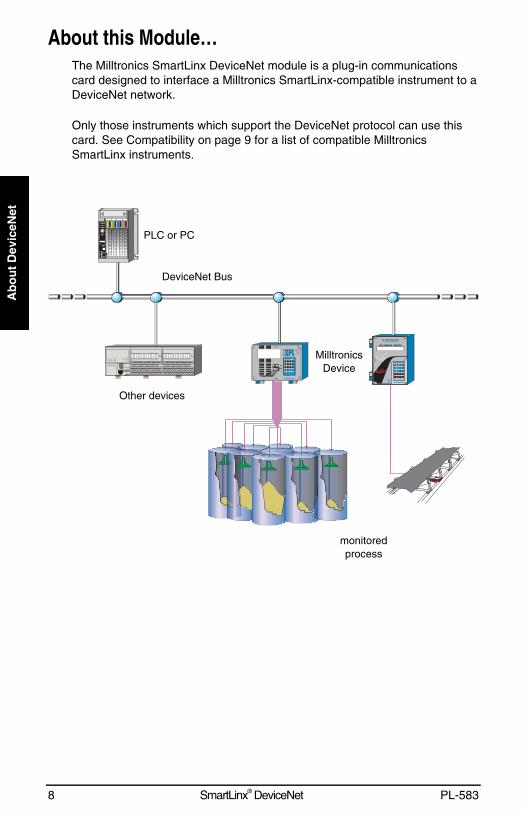
About this Module…The Milltronics SmartLinx DeviceNet module is a plug-in communicationscard designed to interface a Milltronics SmartLinx-compatible instrument to aDeviceNet network.
Only those instruments which support the DeviceNet protocol can use thiscard. See Compatibility on page 9 for a list of compatible MilltronicsSmartLinx instruments.
monitoredprocess
Other devices
PLC or PC
MilltronicsDevice
DeviceNet Bus
PL-583 SmartLinx® DeviceNet 9
Installatio
n
InstallationThe SmartLinx DeviceNet module is shipped installed in the Milltronicsinstrument or separately for on-site installation. Refer to the manual of yourMilltronics instrument for details on module location and installation.
CompatibilityAll available SmartLinx DeviceNet card uses are shown below for reference.
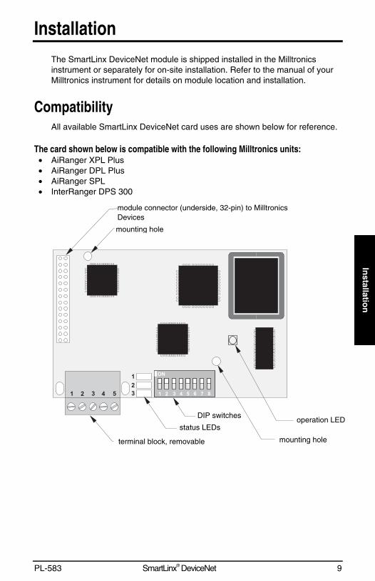
The card shown below is compatible with the following Milltronics units:• AiRanger XPL Plus• AiRanger DPL Plus• AiRanger SPL• InterRanger DPS 300
mounting hole
operation LED
mounting hole
DIP switches
status LEDs
terminal block, removable
module connector (underside, 32-pin) to MilltronicsDevices
10 SmartLinx® DeviceNet PL-583
Inst
alla
tio
n
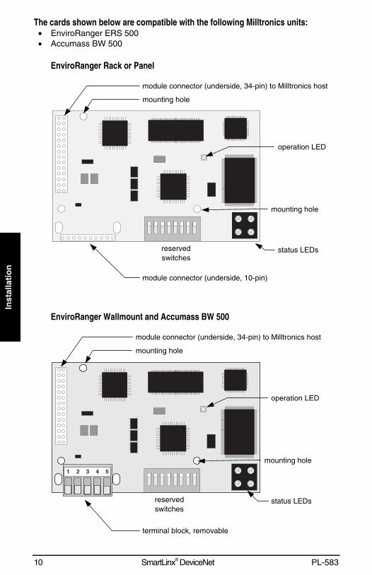
The cards shown below are compatible with the following Milltronics units:• EnviroRanger ERS 500• Accumass BW 500
EnviroRanger Rack or Panel
EnviroRanger Wallmount and Accumass BW 500
reservedswitches
mounting hole
module connector (underside, 34-pin) to Milltronics host
module connector (underside, 10-pin)
status LEDs
mounting hole
operation LED
reservedswitches
mounting hole
module connector (underside, 34-pin) to Milltronics host
status LEDs
mounting hole
operation LED
terminal block, removable
PL-583 SmartLinx® DeviceNet 11
Installatio
n
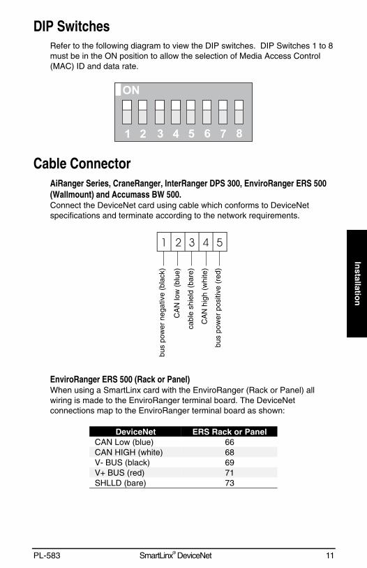
DIP SwitchesRefer to the following diagram to view the DIP switches. DIP Switches 1 to 8must be in the ON position to allow the selection of Media Access Control(MAC) ID and data rate.
Cable ConnectorAiRanger Series, CraneRanger, InterRanger DPS 300, EnviroRanger ERS 500(Wallmount) and Accumass BW 500.Connect the DeviceNet card using cable which conforms to DeviceNetspecifications and terminate according to the network requirements.
EnviroRanger ERS 500 (Rack or Panel)When using a SmartLinx card with the EnviroRanger (Rack or Panel) allwiring is made to the EnviroRanger terminal board. The DeviceNetconnections map to the EnviroRanger terminal board as shown:
DeviceNet ERS Rack or PanelCAN Low (blue) 66CAN HIGH (white) 68V- BUS (black) 69V+ BUS (red) 71SHLLD (bare) 73
bus
pow
er n
egat
ive
(bla
ck)
CA
N lo
w (
blue
)
cabl
e sh
ield
(ba
re)
CA
N h
igh
(whi
te)
bus
pow
er p
ositi
ve (
red)

12 SmartLinx® DeviceNet PL-583
Inst
alla
tio
n
PL-583 SmartLinx® DeviceNet 13
Op
eration
OperationCommunication on the DeviceNet network is indicated by the SmartLinx LED’s.
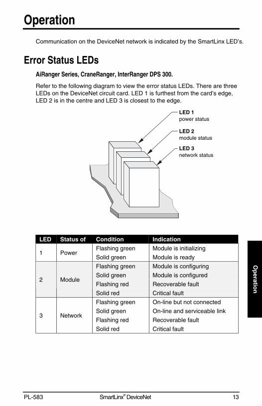
Error Status LEDsAiRanger Series, CraneRanger, InterRanger DPS 300.
Refer to the following diagram to view the error status LEDs. There are threeLEDs on the DeviceNet circuit card. LED 1 is furthest from the card’s edge,LED 2 is in the centre and LED 3 is closest to the edge.
LED Status of Condition Indication
Flashing green Module is initializing1 Power
Solid green Module is ready
Flashing green Module is configuring
Solid green Module is configured
Flashing red Recoverable fault2 Module
Solid red Critical fault
Flashing green On-line but not connected
Solid green On-line and serviceable link
Flashing red Recoverable fault3 Network
Solid red Critical fault
LED 2module status
LED 3network status
LED 1power status
14 SmartLinx® DeviceNet PL-583
Op
erat
ion
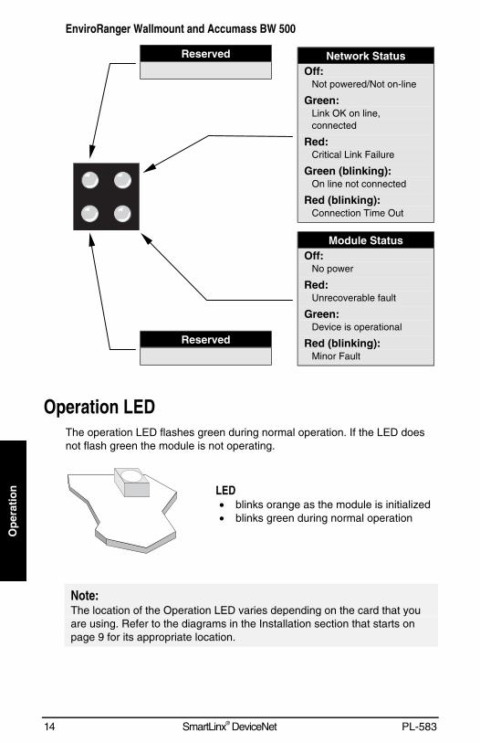
EnviroRanger Wallmount and Accumass BW 500
Operation LEDThe operation LED flashes green during normal operation. If the LED doesnot flash green the module is not operating.
LED• blinks orange as the module is initialized• blinks green during normal operation
Note:The location of the Operation LED varies depending on the card that youare using. Refer to the diagrams in the Installation section that starts onpage 9 for its appropriate location.
Network StatusOff:
Not powered/Not on-line
Green:Link OK on line,connected
Red:Critical Link Failure
Green (blinking):On line not connected
Red (blinking):Connection Time Out
Reserved
Module StatusOff:
No power
Red:Unrecoverable fault
Green:Device is operational
Red (blinking):Minor Fault
Reserved
PL-583 SmartLinx® DeviceNet 15
Co
mm
un
ication
Set-u
p
Communication Set-upThe SmartLinx DeviceNet module is a slave device on the network (ie. it is aDeviceNet Group 2 only server as determined in the predefined master/slaveconnection definitions).
AiRanger Series, CraneRanger and InterRanger DPS 300This card only supports polled I/O with the following setup:
• I/O connection #1 input size of 64 bytes.• I/O connection #1 output size of 26 bytes.
Some configurations may also require some of the following information:
• Device Type is 12(0x0c)• Product code is 7• Vendor ID is 90 (0x5a)
EnviroRanger ERS 500This card only supports polled I/O with the following setup:
• I/O connection #1 input size of 84 bytes.• I/O connection #1 output size of 26 bytes.
Some configurations may also require some of the following information:
• Device Type is 12(0x0c)• Product code is 12• Vendor ID is 90 (0x5a)
Accumass BW 500This card only supports polled I/O with the following setup:
• I/O connection #1 input size of 62 bytes.• I/O connection #1 output size of 38 bytes.
Some configurations may also require some of the following information:
• Device Type is 12(0x0c)• Product code is 12• Vendor ID is 90 (0x5a)
16 SmartLinx® DeviceNet PL-583
Co
mm
un
icat
ion
Set
-up
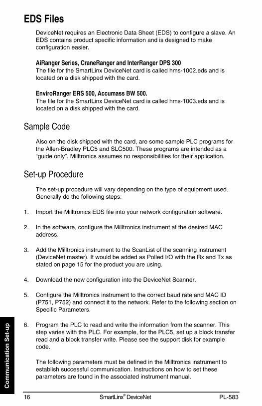
EDS FilesDeviceNet requires an Electronic Data Sheet (EDS) to configure a slave. AnEDS contains product specific information and is designed to makeconfiguration easier.
AiRanger Series, CraneRanger and InterRanger DPS 300The file for the SmartLinx DeviceNet card is called hms-1002.eds and islocated on a disk shipped with the card.
EnviroRanger ERS 500, Accumass BW 500.The file for the SmartLinx DeviceNet card is called hms-1003.eds and islocated on a disk shipped with the card.
Sample Code
Also on the disk shipped with the card, are some sample PLC programs forthe Allen-Bradley PLC5 and SLC500. These programs are intended as a“guide only”. Milltronics assumes no responsibilities for their application.
Set-up Procedure
The set-up procedure will vary depending on the type of equipment used.Generally do the following steps:
1. Import the Milltronics EDS file into your network configuration software.
2. In the software, configure the Milltronics instrument at the desired MACaddress.
3. Add the Milltronics instrument to the ScanList of the scanning instrument(DeviceNet master). It would be added as Polled I/O with the Rx and Tx asstated on page 15 for the product you are using.
4. Download the new configuration into the DeviceNet Scanner.
5. Configure the Milltronics instrument to the correct baud rate and MAC ID(P751, P752) and connect it to the network. Refer to the following section onSpecific Parameters.
6. Program the PLC to read and write the information from the scanner. Thisstep varies with the PLC. For example, for the PLC5, set up a block transferread and a block transfer write. Please see the support disk for examplecode.
The following parameters must be defined in the Milltronics instrument toestablish successful communication. Instructions on how to set theseparameters are found in the associated instrument manual.
PL-583 SmartLinx® DeviceNet 17
Co
mm
un
ication
Set-u
p
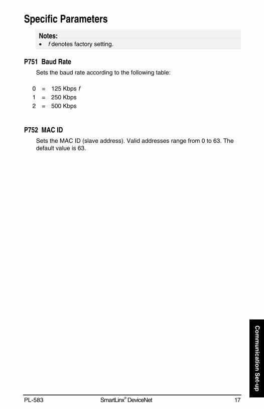
Specific ParametersNotes:• f denotes factory setting.
P751 Baud RateSets the baud rate according to the following table:
0 = 125 Kbps f1 = 250 Kbps2 = 500 Kbps
P752 MAC IDSets the MAC ID (slave address). Valid addresses range from 0 to 63. Thedefault value is 63.

18 SmartLinx® DeviceNet PL-583
Co
mm
un
icat
ion
Set
-up
PL-583 SmartLinx® DeviceNet 19
Ap
plicatio
n L
ayer
Application LayerThis section describes the meanings of data read from, and written to theMilltronics instrument memory via the SmartLinx DeviceNet connection. Theoutput words (PLC master write operation) and input words (PLC masterread operation) are described in three areas within this section of themanual. For the AiRanger series of products, refer to the Data Map on page24. For the EnviroRanger series, refer to the Data Map on page 30. For theAccumass BW 500, refer to the Data Map on page 36.
Note:Parameter P999 (Master Reset) is not accessible via the SmartLinxinterface on Level products.
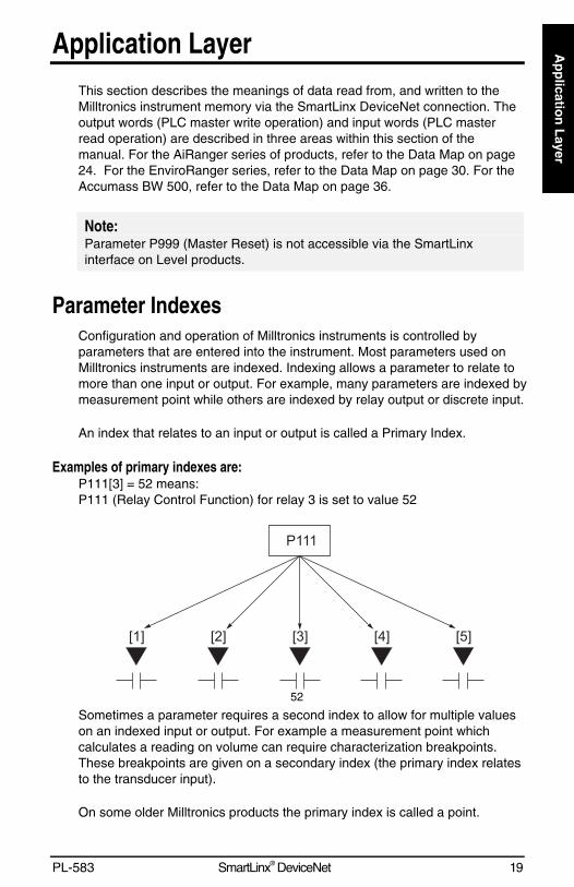
Parameter IndexesConfiguration and operation of Milltronics instruments is controlled byparameters that are entered into the instrument. Most parameters used onMilltronics instruments are indexed. Indexing allows a parameter to relate tomore than one input or output. For example, many parameters are indexed bymeasurement point while others are indexed by relay output or discrete input.
An index that relates to an input or output is called a Primary Index.
Examples of primary indexes are:P111[3] = 52 means:P111 (Relay Control Function) for relay 3 is set to value 52
Sometimes a parameter requires a second index to allow for multiple valueson an indexed input or output. For example a measurement point whichcalculates a reading on volume can require characterization breakpoints.These breakpoints are given on a secondary index (the primary index relatesto the transducer input).
On some older Milltronics products the primary index is called a point.
52
20 SmartLinx® DeviceNet PL-583
Ap
plic
atio
n L
ayer
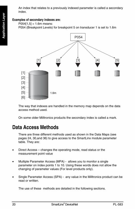
An index that relates to a previously indexed parameter is called a secondaryindex.
Examples of secondary indexes are:P054[1,5] = 1.6m means:P054 (Breakpoint Levels) for breakpoint 5 on transducer 1 is set to 1.6m
The way that indexes are handled in the memory map depends on the dataaccess method used.
On some older Milltronics products the secondary index is called a mark.
Data Access MethodsThere are three different methods used as shown in the Data Maps (seepages 24, 30,and 36) to give access to the SmartLinx module parametertable. They are:
• Direct Access – changes the operating mode, read status or themeasurement point value
• Multiple Parameter Access (MPA) - allows you to monitor a singleparameter on index points 1 to 10. Using these words does not allow thechanging of parameter values (For level products only).
• Single Parameter Access (SPA) - any value in the Milltronics product can beread or written.
The use of these methods are detailed in the following sections.
1.6m
PL-583 SmartLinx® DeviceNet 21
Ap
plicatio
n L
ayer
Direct Access
Certain values are mapped directly into words. These words can bemonitored continuously.
Multiple Parameter Access (MPA)
This is a hand-shaking method where the user writes the parameter number,secondary index, decimal place, and format. Then, the instrument providesthe values of the requested parameter for the primary index 1 to 10.
Note:In Milltronics’ products, the memory is arranged as Parameter number,Primary Index, Secondary Index.
Using Multiple Parameter Access (MPA)MPA allows you to monitor a single parameter on index points 1 to 10. Usingthese words does not allow the changing of parameter values.
1. In the output table of the PLC (Write Block) write the values for theparameter number, secondary Index, decimal place and format in the correctlocation.
2. Monitor the Input table of the PLC (Read Block), and watch for the valuesyou wrote to appear in the appropriate locations of the read block, then go toStep 3.
3. Read the requested values in the appropriate location of the Read Block.These values are continuously updated. Continue reading from these wordsuntil values for another parameter are required, then go back to step 1.
Note:MPA values are only updated in Run mode (word 12 = 0).
Parameter Indexing with MPAPrimary IndexThe primary index is implicit in the memory address. MPA values arereturned through 10 words of the read block (see pages 27 and 33).
Secondary IndexThe secondary index is nearly always left at zero. See the manual for theMilltronics instrument for information on parameters which require asecondary index.
22 SmartLinx® DeviceNet PL-583
Ap
plic
atio
n L
ayer
Single Parameter Access (SPA)
This is a hand-shaking method where the PLC specifies:
• parameter number• primary index• secondary index• decimal place• format• read/write flag• value
With this method, any value in the Milltronics product can be read or written.
Using Single Parameter Access (SPA)SPA, allows continuous monitoring or demand programming of a parameter.
Reading a Parameter1. Set the Read/Write flag in the output table (Write Block) to 0, “read”.
2. Write the Parameter Number, Primary Index, Secondary Index, DecimalPlace and Format in the correct locations.
NoteIf there is no secondary index, then place a 0 in this location.
3. Monitor the Input table of the PLC (Read Block) and watch for the values youwrote to appear in the appropriate locations, then go to Step 4.
4. Read the requested parameter value in the Input table (Read Block). Thesevalues are continuously updated. Continue reading from these words untilvalues for other parameters are required. At that time, go back to step 1.
Writing a Parameter1. Set the Read/Write flag in the output table (Write Block) to 0, “read”.
2. Write the Parameter Number, Primary Index, Secondary Index, DecimalPlace and Format in the correct locations.
3. Write the new value of the parameter into the correct location of the outputmemory (Write Block)
4. Verify the unit is in program mode (not needed for BW500). For Level see bit10 of status word in Read Block.
PL-583 SmartLinx® DeviceNet 23
Ap
plicatio
n L
ayer
5. If it is not in program mode, write a 1 to the operating mode word in theoutput memory (Write Block). Please note that this will only work if the wordis already a 0 (ie. it only works as a transition).
6. Set the Read / Write flag in the output table (Write Block) to a 1 “write”.
7. Monitor the Input table of the PLC (read block) and watch for the values youwrote to appear in the appropriate locations.
8. Set Read / Write flag back to 0.
9. Place unit in Run mode.
Note (does not apply to Accumass BW-500):Parameters can only be written in Program mode (word 12 = 1). If the hostinstrument is still in Run mode then any written values are ignored.
24 SmartLinx® DeviceNet PL-583
Ap
plic
atio
n L
ayer
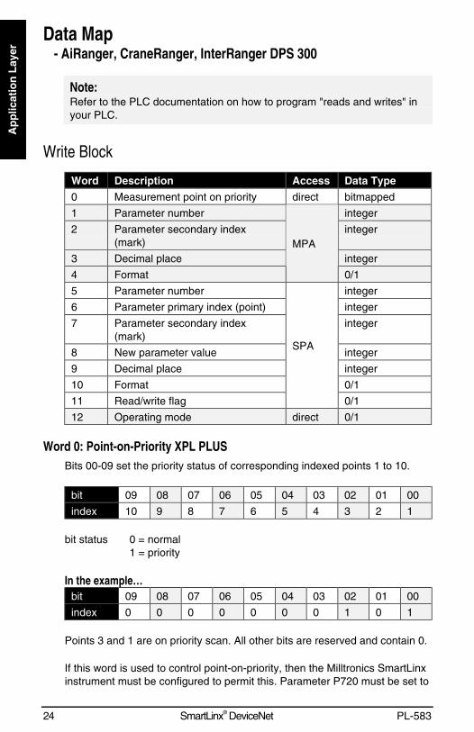
Data Map- AiRanger, CraneRanger, InterRanger DPS 300
Note:Refer to the PLC documentation on how to program "reads and writes" inyour PLC.
Write Block
Word Description Access Data Type
0 Measurement point on priority direct bitmapped
1 Parameter number integer
2 Parameter secondary index(mark)
integer
3 Decimal place integer
4 Format
MPA
0/1
5 Parameter number integer
6 Parameter primary index (point) integer
7 Parameter secondary index(mark)
integer
8 New parameter value integer
9 Decimal place integer
10 Format 0/1
11 Read/write flag
SPA
0/1
12 Operating mode direct 0/1
Word 0: Point-on-Priority XPL PLUSBits 00-09 set the priority status of corresponding indexed points 1 to 10.
bit 09 08 07 06 05 04 03 02 01 00
index 10 9 8 7 6 5 4 3 2 1
bit status 0 = normal1 = priority
In the example…bit 09 08 07 06 05 04 03 02 01 00
index 0 0 0 0 0 0 0 1 0 1
Points 3 and 1 are on priority scan. All other bits are reserved and contain 0.
If this word is used to control point-on-priority, then the Milltronics SmartLinxinstrument must be configured to permit this. Parameter P720 must be set to
PL-583 SmartLinx® DeviceNet 25
Ap
plicatio
n L
ayer
1 (manual, BIC-II or SmartLinx SPA) for each point to permit priority controlfor that point.
To enable priority control for all indexed measurement points use SPA tostore “1” to parameter P720, index 0 (P720[0]).
Word 1: Parameter Number, MPASpecifies the parameter number for the returned values in words 11 to 20.See Read Block on page 27.
Word 2: Parameter Secondary Index, MPASpecifies the secondary index for the parameter specified by word 1. Thisword is ignored for parameters that do not use multiple indexes. SeeParameter Indexes on page 19 for more information.
Note:The Primary Index is implicit in the word location where word 11 = index 1and word 20 = index 10.
Word 3: Decimal Place, MPASpecifies the number of decimal places to shift the returned values. Thisaffects words 11 to 20.
Positive values indicate that the decimal place shifts to the left.
i.e. A “1” means that all returned values have the decimal place shifted 1space to the left and a returned value of 5,213 is interpreted as 521.3.
Negative values indicate that the decimal place shifts to the right.
i.e. If this word is “-1”, a returned value of 5,213 is interpreted as 52,130.
Word 4: Format, MPASets the format for the returned values in word 11 to 20.
0 = normal1 = percent
Word 5: Parameter, SPASpecifies the requested parameter number.
Word 6: Primary Index, SPASpecifies the primary index number for the parameter in word 5.
26 SmartLinx® DeviceNet PL-583
Ap
plic
atio
n L
ayer
Word 7: Secondary Index, SPASpecifies the secondary index for the parameter in word 5. This word isignored for parameters that don’t use multiple indexes. See ParameterIndexes on page 29 for more information.
Word 8: Value, SPAThis word contains the value written to the specified parameter and index.The format of this word is specified by words 9 to 10.
To write a value, ensure word 11 = 1 and word 12 =1.
See also Data Types on page 44.
Word 9: Decimal Place, SPAThis word specifies the number of decimal places for the value in word 8,and also for the parameter value returned in word 28.
Positive values indicate that the decimal place shifts to the left.
i.e. A 1 means that all returned values have the decimal place shifted 1space to the left and a returned value of 5,213 is interpreted as 521.3.
Negative values indicate that the decimal place shifts to the right.
i.e. If this word is “-1”, a returned value of 5,213 is interpreted as52,130.Word 10: Format, SPA
This word sets the format for the value in word 8, and also for the parametervalue returned in word 28.
0 = normal1 = percent
Word 11: Read/Write Flag, SPAThis word instructs the read/write application of word 8.
0 = read parameter as described by words 5, 6, 7, 9 and 10; word 8 ignored1 = set parameter to the value described by words 5 to 10
Word 12: Operating Mode, SPAThis word sets the operating mode of the Milltronics SmartLinx instrument.
The operating mode can get out of sync if the remote instrument resets backto run mode locally. This can happen due to a timeout or through localprogramming. The mode is always reported correctly through the Readblock. See bit 10 of Word 0: Instrument Status on page 27.
PL-583 SmartLinx® DeviceNet 27
Ap
plicatio
n L
ayer
To reset the instrument to program mode you must write “0” to put theSmartLinx module back in sync with the instrument and then write “1” to setthe instrument to program mode.
0 = run mode1 = program mode
Read Block
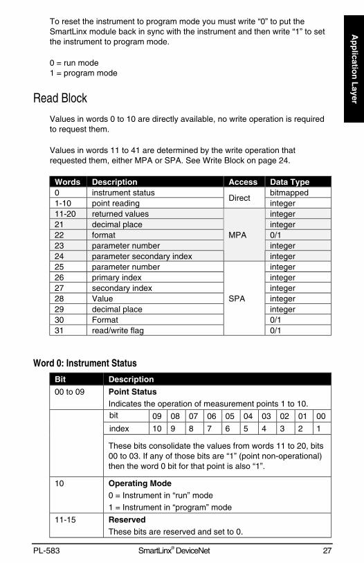
Values in words 0 to 10 are directly available, no write operation is requiredto request them.
Values in words 11 to 41 are determined by the write operation thatrequested them, either MPA or SPA. See Write Block on page 24.
Words Description Access Data Type0 instrument status bitmapped1-10 point reading
Directinteger
11-20 returned values integer21 decimal place integer22 format 0/123 parameter number integer24 parameter secondary index
MPA
integer25 parameter number integer26 primary index integer27 secondary index integer28 Value integer29 decimal place integer30 Format 0/131 read/write flag
SPA
0/1
Word 0: Instrument Status
Bit Description
00 to 09 Point StatusIndicates the operation of measurement points 1 to 10.bit 09 08 07 06 05 04 03 02 01 00
index 10 9 8 7 6 5 4 3 2 1
These bits consolidate the values from words 11 to 20, bits00 to 03. If any of those bits are “1” (point non-operational)then the word 0 bit for that point is also “1”.
10 Operating Mode0 = Instrument in “run” mode1 = Instrument in “program” mode
11-15 ReservedThese bits are reserved and set to 0.
28 SmartLinx® DeviceNet PL-583
Ap
plic
atio
n L
ayer
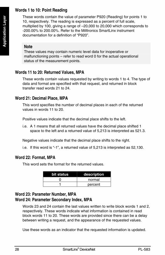
Words 1 to 10: Point ReadingThese words contain the value of parameter P920 (Reading) for points 1 to10, respectively. The reading is expressed as a percent of full scale,multiplied by 100, giving a range of –20,000 to 20,000 which corresponds to-200.00% to 200.00%. Refer to the Milltronics SmartLinx instrumentdocumentation for a definition of “P920”.
NoteThese values may contain numeric level data for inoperative ormalfunctioning points – refer to read word 0 for the actual operationalstatus of the measurement points.
Words 11 to 20: Returned Values, MPAThese words contain values requested by writing to words 1 to 4. The type ofdata and format are specified with that request, and returned in blocktransfer read words 21 to 24.
Word 21: Decimal Place, MPAThis word specifies the number of decimal places in each of the returnedvalues in words 11 to 20.
Positive values indicate that the decimal place shifts to the left.
i.e. A 1 means that all returned values have the decimal place shifted 1space to the left and a returned value of 5,213 is interpreted as 521.3.
Negative values indicate that the decimal place shifts to the right.
i.e. If this word is “-1”, a returned value of 5,213 is interpreted as 52,130.
Word 22: Format, MPAThis word sets the format for the returned values.
bit status description0 normal1 percent
Word 23: Parameter Number, MPAWord 24: Parameter Secondary Index, MPA
Words 23 and 24 contain the last values written to write block words 1 and 2,respectively. These words indicate what information is contained in readblock words 11 to 20. These words are provided since there can be a delaybetween writing a request, and the appearance of the requested values.
Use these words as an indicator that the requested information is updated.
PL-583 SmartLinx® DeviceNet 29
Ap
plicatio
n L
ayer
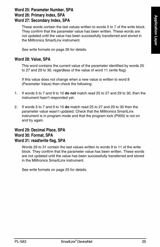
Word 25: Parameter Number, SPAWord 26: Primary Index, SPAWord 27: Secondary Index, SPA
These words contain the last values written to words 5 to 7 of the write block.They confirm that the parameter value has been written. These words arenot updated until the value has been successfully transferred and stored inthe Milltronics SmartLinx instrument.
See write formats on page 26 for details.
Word 28: Value, SPAThis word contains the current value of the parameter identified by words 25to 27 and 29 to 30, regardless of the value of word 11 (write flag).
If this value does not change when a new value is written to word 8(Parameter Value) then check the following:
1. If words 5 to 7 and 9 to 10 do not match read 25 to 27 and 29 to 30, then theinstrument hasn’t responded yet.
2. If words 5 to 7 and 9 to 10 do match read 25 to 27 and 29 to 30 then theparameter value wasn’t updated. Check that the Milltronics SmartLinxinstrument is in program mode and that the program lock (P000) is not onand try again.
Word 29: Decimal Place, SPAWord 30: Format, SPAWord 31: read/write flag, SPA
Words 29 to 31 contain the last values written to words 9 to 11 of the writeblock. They confirm that the parameter value has been written. These wordsare not updated until the value has been successfully transferred and storedin the Milltronics SmartLinx instrument.
See write formats on page 25 for details.
30 SmartLinx® DeviceNet PL-583
Ap
plic
atio
n L
ayer
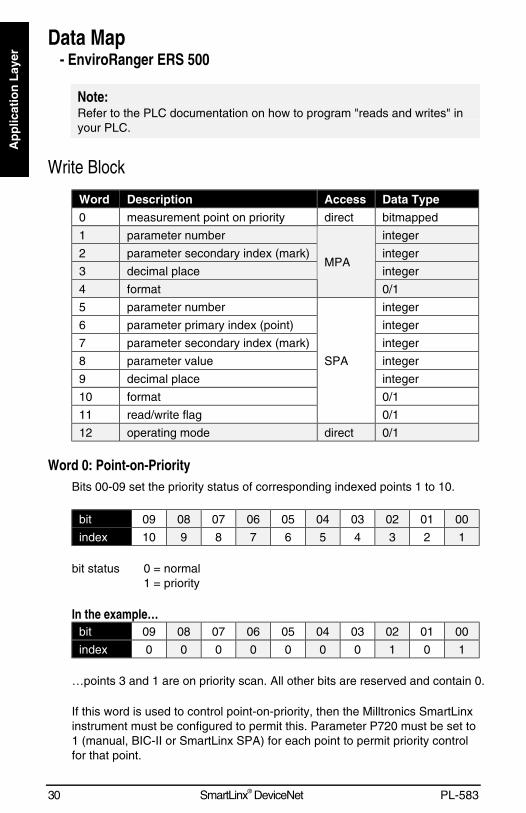
Data Map- EnviroRanger ERS 500
Note:Refer to the PLC documentation on how to program "reads and writes" inyour PLC.
Write Block
Word Description Access Data Type
0 measurement point on priority direct bitmapped
1 parameter number integer
2 parameter secondary index (mark) integer
3 decimal place integer
4 format
MPA
0/1
5 parameter number integer
6 parameter primary index (point) integer
7 parameter secondary index (mark) integer
8 parameter value integer
9 decimal place integer
10 format 0/1
11 read/write flag
SPA
0/1
12 operating mode direct 0/1
Word 0: Point-on-PriorityBits 00-09 set the priority status of corresponding indexed points 1 to 10.
bit 09 08 07 06 05 04 03 02 01 00
index 10 9 8 7 6 5 4 3 2 1
bit status 0 = normal1 = priority
In the example…bit 09 08 07 06 05 04 03 02 01 00
index 0 0 0 0 0 0 0 1 0 1
…points 3 and 1 are on priority scan. All other bits are reserved and contain 0.
If this word is used to control point-on-priority, then the Milltronics SmartLinxinstrument must be configured to permit this. Parameter P720 must be set to1 (manual, BIC-II or SmartLinx SPA) for each point to permit priority controlfor that point.
PL-583 SmartLinx® DeviceNet 31
Ap
plicatio
n L
ayer
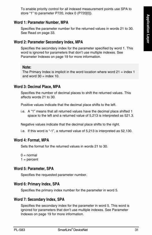
To enable priority control for all indexed measurement points use SPA tostore “1” to parameter P720, index 0 (P720[0]).
Word 1: Parameter Number, MPASpecifies the parameter number for the returned values in words 21 to 30.See Read on page 33.
Word 2: Parameter Secondary Index, MPASpecifies the secondary index for the parameter specified by word 1. Thisword is ignored for parameters that don’t use multiple indexes. SeeParameter Indexes on page 19 for more information.
Note:The Primary Index is implicit in the word location where word 21 = index 1and word 30 = index 10.
Word 3: Decimal Place, MPASpecifies the number of decimal places to shift the returned values. Thisaffects words 21 to 30.
Positive values indicate that the decimal place shifts to the left.
i.e. A “1” means that all returned values have the decimal place shifted 1space to the left and a returned value of 5,213 is interpreted as 521.3.
Negative values indicate that the decimal place shifts to the right.
i.e. If this word is “-1”, a returned value of 5,213 is interpreted as 52,130.
Word 4: Format, MPASets the format for the returned values in words 21 to 30.
0 = normal1 = percent
Word 5: Parameter, SPASpecifies the requested parameter number.
Word 6: Primary Index, SPASpecifies the primary index number for the parameter in word 5.
Word 7: Secondary Index, SPASpecifies the secondary index for the parameter in word 5. This word isignored for parameters that don’t use multiple indexes. See ParameterIndexes on page 19 for more information.
32 SmartLinx® DeviceNet PL-583
Ap
plic
atio
n L
ayer
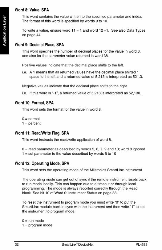
Word 8: Value, SPAThis word contains the value written to the specified parameter and index.The format of this word is specified by words 9 to 10.
To write a value, ensure word 11 = 1 and word 12 =1. See also Data Typeson page 44.
Word 9: Decimal Place, SPAThis word specifies the number of decimal places for the value in word 8,and also for the parameter value returned in word 38.
Positive values indicate that the decimal place shifts to the left.
i.e. A 1 means that all returned values have the decimal place shifted 1space to the left and a returned value of 5,213 is interpreted as 521.3.
Negative values indicate that the decimal place shifts to the right.
i.e. If this word is “-1”, a returned value of 5,213 is interpreted as 52,130.
Word 10: Format, SPAThis word sets the format for the value in word 8.
0 = normal1 = percent
Word 11: Read/Write Flag, SPAThis word instructs the read/write application of word 8.
0 = read parameter as described by words 5, 6, 7, 9 and 10; word 8 ignored1 = set parameter to the value described by words 5 to 10
Word 12: Operating Mode, SPAThis word sets the operating mode of the Milltronics SmartLinx instrument.
The operating mode can get out of sync if the remote instrument resets backto run mode locally. This can happen due to a timeout or through localprogramming. The mode is always reported correctly through the Readblock. See bit 10 of Word 0: Instrument Status on page 33.
To reset the instrument to program mode you must write “0” to put theSmartLinx module back in sync with the instrument and then write “1” to setthe instrument to program mode.
0 = run mode1 = program mode
PL-583 SmartLinx® DeviceNet 33
Ap
plicatio
n L
ayer
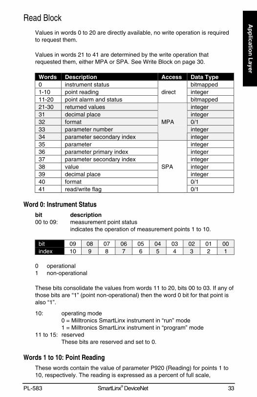
Read Block
Values in words 0 to 20 are directly available, no write operation is requiredto request them.
Values in words 21 to 41 are determined by the write operation thatrequested them, either MPA or SPA. See Write Block on page 30.
Words Description Access Data Type0 instrument status bitmapped1-10 point reading integer11-20 point alarm and status
directbitmapped
21-30 returned values integer31 decimal place integer32 format 0/133 parameter number integer34 parameter secondary index
MPA
integer35 parameter integer36 parameter primary index integer37 parameter secondary index integer38 value integer39 decimal place integer40 format 0/141 read/write flag
SPA
0/1
Word 0: Instrument Statusbit description00 to 09: measurement point status
indicates the operation of measurement points 1 to 10.
bit 09 08 07 06 05 04 03 02 01 00index 10 9 8 7 6 5 4 3 2 1
0 operational1 non-operational
These bits consolidate the values from words 11 to 20, bits 00 to 03. If any ofthose bits are “1” (point non-operational) then the word 0 bit for that point isalso “1”.
10: operating mode0 = Milltronics SmartLinx instrument in “run” mode1 = Milltronics SmartLinx instrument in “program” mode
11 to 15: reservedThese bits are reserved and set to 0.
Words 1 to 10: Point ReadingThese words contain the value of parameter P920 (Reading) for points 1 to10, respectively. The reading is expressed as a percent of full scale,
34 SmartLinx® DeviceNet PL-583
Ap
plic
atio
n L
ayer
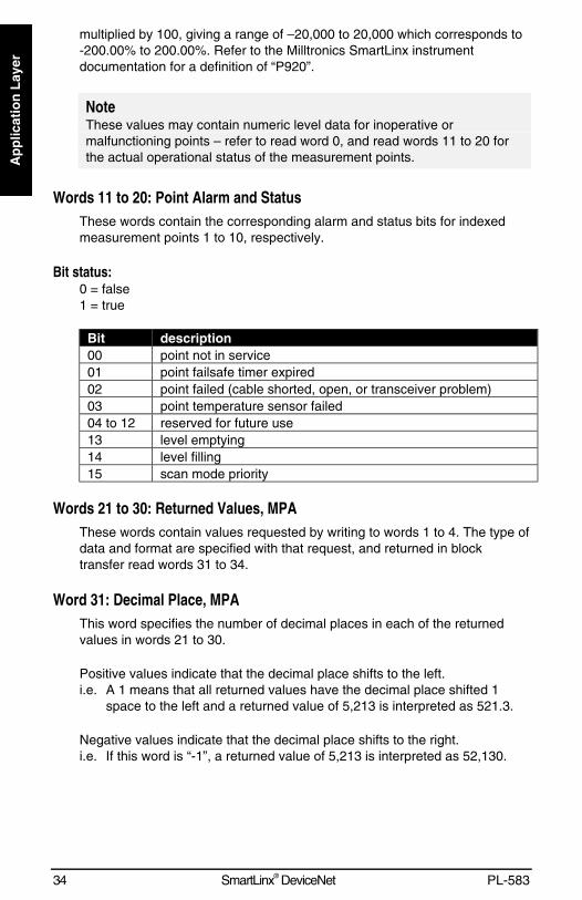
multiplied by 100, giving a range of –20,000 to 20,000 which corresponds to-200.00% to 200.00%. Refer to the Milltronics SmartLinx instrumentdocumentation for a definition of “P920”.
NoteThese values may contain numeric level data for inoperative ormalfunctioning points – refer to read word 0, and read words 11 to 20 forthe actual operational status of the measurement points.
Words 11 to 20: Point Alarm and StatusThese words contain the corresponding alarm and status bits for indexedmeasurement points 1 to 10, respectively.
Bit status:0 = false1 = true
Bit description00 point not in service01 point failsafe timer expired02 point failed (cable shorted, open, or transceiver problem)03 point temperature sensor failed04 to 12 reserved for future use13 level emptying14 level filling15 scan mode priority
Words 21 to 30: Returned Values, MPAThese words contain values requested by writing to words 1 to 4. The type ofdata and format are specified with that request, and returned in blocktransfer read words 31 to 34.
Word 31: Decimal Place, MPAThis word specifies the number of decimal places in each of the returnedvalues in words 21 to 30.
Positive values indicate that the decimal place shifts to the left.i.e. A 1 means that all returned values have the decimal place shifted 1
space to the left and a returned value of 5,213 is interpreted as 521.3.
Negative values indicate that the decimal place shifts to the right.i.e. If this word is “-1”, a returned value of 5,213 is interpreted as 52,130.
PL-583 SmartLinx® DeviceNet 35
Ap
plicatio
n L
ayer
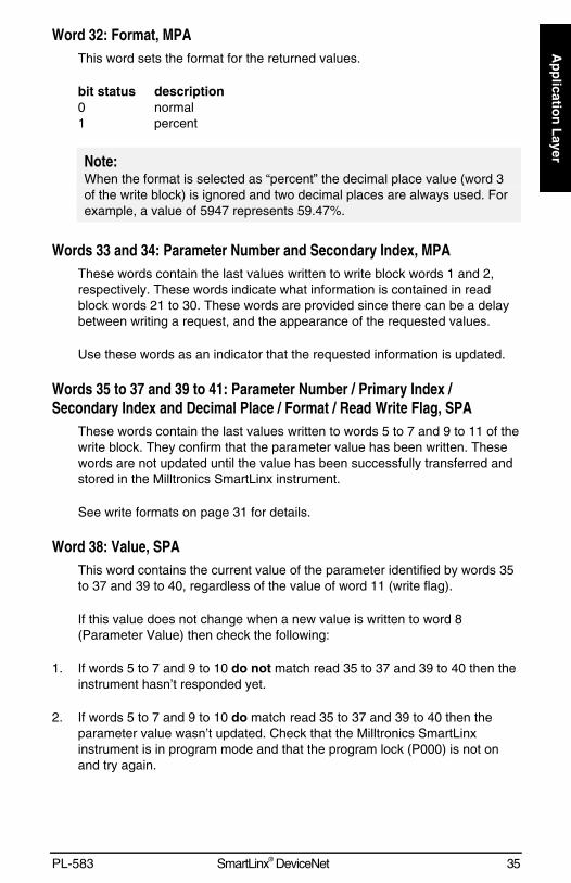
Word 32: Format, MPAThis word sets the format for the returned values.
bit status description0 normal1 percent
Note:When the format is selected as “percent” the decimal place value (word 3of the write block) is ignored and two decimal places are always used. Forexample, a value of 5947 represents 59.47%.
Words 33 and 34: Parameter Number and Secondary Index, MPAThese words contain the last values written to write block words 1 and 2,respectively. These words indicate what information is contained in readblock words 21 to 30. These words are provided since there can be a delaybetween writing a request, and the appearance of the requested values.
Use these words as an indicator that the requested information is updated.
Words 35 to 37 and 39 to 41: Parameter Number / Primary Index /Secondary Index and Decimal Place / Format / Read Write Flag, SPA
These words contain the last values written to words 5 to 7 and 9 to 11 of thewrite block. They confirm that the parameter value has been written. Thesewords are not updated until the value has been successfully transferred andstored in the Milltronics SmartLinx instrument.
See write formats on page 31 for details.
Word 38: Value, SPAThis word contains the current value of the parameter identified by words 35to 37 and 39 to 40, regardless of the value of word 11 (write flag).
If this value does not change when a new value is written to word 8(Parameter Value) then check the following:
1. If words 5 to 7 and 9 to 10 do not match read 35 to 37 and 39 to 40 then theinstrument hasn’t responded yet.
2. If words 5 to 7 and 9 to 10 do match read 35 to 37 and 39 to 40 then theparameter value wasn’t updated. Check that the Milltronics SmartLinxinstrument is in program mode and that the program lock (P000) is not onand try again.
36 SmartLinx® DeviceNet PL-583
Ap
plic
atio
n L
ayer
Data Map- Accumass BW 500
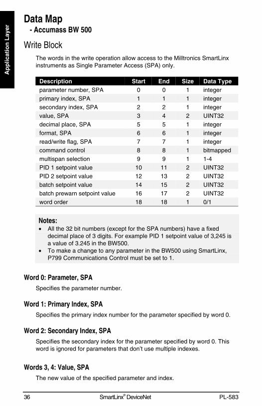
Write BlockThe words in the write operation allow access to the Milltronics SmartLinxinstruments as Single Parameter Access (SPA) only.
Description Start End Size Data Typeparameter number, SPA 0 0 1 integerprimary index, SPA 1 1 1 integersecondary index, SPA 2 2 1 integervalue, SPA 3 4 2 UINT32decimal place, SPA 5 5 1 integerformat, SPA 6 6 1 integerread/write flag, SPA 7 7 1 integercommand control 8 8 1 bitmappedmultispan selection 9 9 1 1-4PID 1 setpoint value 10 11 2 UINT32PID 2 setpoint value 12 13 2 UINT32batch setpoint value 14 15 2 UINT32batch prewarn setpoint value 16 17 2 UINT32word order 18 18 1 0/1
Notes:• All the 32 bit numbers (except for the SPA numbers) have a fixed
decimal place of 3 digits. For example PID 1 setpoint value of 3,245 isa value of 3.245 in the BW500.
• To make a change to any parameter in the BW500 using SmartLinx,P799 Communications Control must be set to 1.
Word 0: Parameter, SPASpecifies the parameter number.
Word 1: Primary Index, SPASpecifies the primary index number for the parameter specified by word 0.
Word 2: Secondary Index, SPASpecifies the secondary index for the parameter specified by word 0. Thisword is ignored for parameters that don’t use multiple indexes.
Words 3, 4: Value, SPAThe new value of the specified parameter and index.
PL-583 SmartLinx® DeviceNet 37
Ap
plicatio
n L
ayer
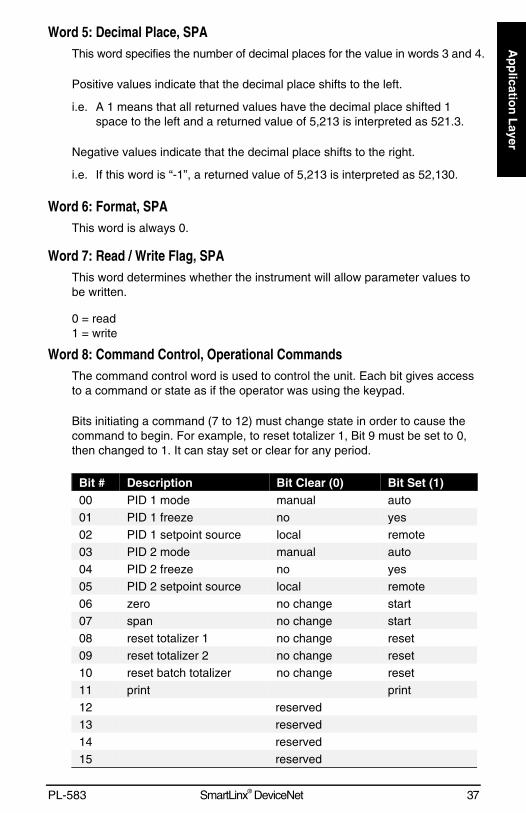
Word 5: Decimal Place, SPAThis word specifies the number of decimal places for the value in words 3 and 4.
Positive values indicate that the decimal place shifts to the left.
i.e. A 1 means that all returned values have the decimal place shifted 1space to the left and a returned value of 5,213 is interpreted as 521.3.
Negative values indicate that the decimal place shifts to the right.
i.e. If this word is “-1”, a returned value of 5,213 is interpreted as 52,130.
Word 6: Format, SPAThis word is always 0.
Word 7: Read / Write Flag, SPAThis word determines whether the instrument will allow parameter values tobe written.
0 = read1 = write
Word 8: Command Control, Operational CommandsThe command control word is used to control the unit. Each bit gives accessto a command or state as if the operator was using the keypad.
Bits initiating a command (7 to 12) must change state in order to cause thecommand to begin. For example, to reset totalizer 1, Bit 9 must be set to 0,then changed to 1. It can stay set or clear for any period.
Bit # Description Bit Clear (0) Bit Set (1)00 PID 1 mode manual auto01 PID 1 freeze no yes02 PID 1 setpoint source local remote03 PID 2 mode manual auto04 PID 2 freeze no yes05 PID 2 setpoint source local remote06 zero no change start07 span no change start08 reset totalizer 1 no change reset09 reset totalizer 2 no change reset10 reset batch totalizer no change reset11 print print12 reserved13 reserved14 reserved15 reserved
38 SmartLinx® DeviceNet PL-583
Ap
plic
atio
n L
ayer
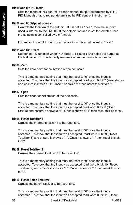
Bit 00 and 03: PID ModeSets the mode of PID control to either manual (output determined by P410 –PID Manual) or auto (output determined by PID control in instrument).
Bit 02 and 05 Setpoint SourceControls the location of the setpoint. If it is set as “local”, then the setpointused is internal to the BW500. If the setpoint source is set to “remote”, thenthe setpoint is controlled by a mA input.
For setpoint control through communications this must be set to “local.”
Bit 01 and 04: FreezeSuspends PID function when PID Mode = 1 (“auto”) and holds the output atthe last value. PID functionality resumes when the freeze bit is cleared.
Bit 06: ZeroSets the zero point for calibration of the belt scale.
This is a momentary setting that must be reset to “0” once the input isaccepted. To check that the input was accepted read word 0, bit 7 (zero status)and ensure it shows a “1”. Once it shows a “1” then reset this bit to “0”.
Bit 07: SpanSets the span for calibration of the belt scale.
This is a momentary setting that must be reset to “0” once the input isaccepted. To check that the input was accepted read word 0, bit 8 (SpanStatus) and ensure it shows a “1”. Once it shows a “1” then reset this bit to “0”.
Bit 08: Reset Totalizer 1Causes the internal totalizer 1 to be reset to 0.
This is a momentary setting that must be reset to “0” once the input isaccepted. To check that the input was accepted, read word 0, bit 9 (ResetTotalizer 1) and ensure it shows a “1”. Once it shows a “1” then reset this bitto “0”.
Bit 09: Reset Totalizer 2Causes the internal totalizer 2 to be reset to 0.
This is a momentary setting that must be reset to “0” once the input isaccepted. To check that the input was accepted read word 0, bit 10 (ResetTotalizer 2) and ensure it shows a “1”. Once it shows a “1” then reset this bitto “0”.
Bit 10: Reset Batch TotalizerCauses the batch totalizer to be reset to 0.
This is a momentary setting that must be reset to “0” once the input isaccepted. To check that the input was accepted read word 0, bit 11 (Reset
PL-583 SmartLinx® DeviceNet 39
Ap
plicatio
n L
ayer
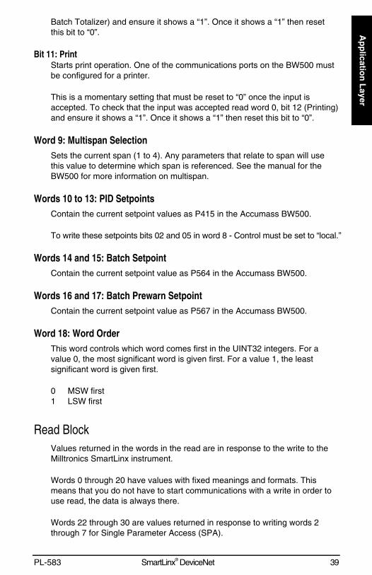
Batch Totalizer) and ensure it shows a “1”. Once it shows a “1” then resetthis bit to “0”.
Bit 11: PrintStarts print operation. One of the communications ports on the BW500 mustbe configured for a printer.
This is a momentary setting that must be reset to “0” once the input isaccepted. To check that the input was accepted read word 0, bit 12 (Printing)and ensure it shows a “1”. Once it shows a “1” then reset this bit to “0”.
Word 9: Multispan SelectionSets the current span (1 to 4). Any parameters that relate to span will usethis value to determine which span is referenced. See the manual for theBW500 for more information on multispan.
Words 10 to 13: PID SetpointsContain the current setpoint values as P415 in the Accumass BW500.
To write these setpoints bits 02 and 05 in word 8 - Control must be set to “local.”
Words 14 and 15: Batch SetpointContain the current setpoint value as P564 in the Accumass BW500.
Words 16 and 17: Batch Prewarn SetpointContain the current setpoint value as P567 in the Accumass BW500.
Word 18: Word OrderThis word controls which word comes first in the UINT32 integers. For avalue 0, the most significant word is given first. For a value 1, the leastsignificant word is given first.
0 MSW first1 LSW first
Read BlockValues returned in the words in the read are in response to the write to theMilltronics SmartLinx instrument.
Words 0 through 20 have values with fixed meanings and formats. Thismeans that you do not have to start communications with a write in order touse read, the data is always there.
Words 22 through 30 are values returned in response to writing words 2through 7 for Single Parameter Access (SPA).
40 SmartLinx® DeviceNet PL-583
Ap
plic
atio
n L
ayer
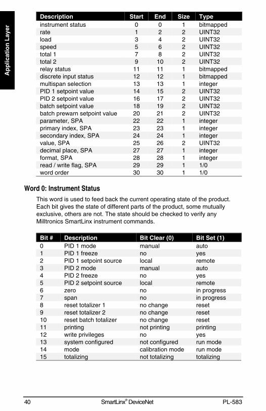
Description Start End Size Typeinstrument status 0 0 1 bitmappedrate 1 2 2 UINT32load 3 4 2 UINT32speed 5 6 2 UINT32total 1 7 8 2 UINT32total 2 9 10 2 UINT32relay status 11 11 1 bitmappeddiscrete input status 12 12 1 bitmappedmultispan selection 13 13 1 integerPID 1 setpoint value 14 15 2 UINT32PID 2 setpoint value 16 17 2 UINT32batch setpoint value 18 19 2 UINT32batch prewarn setpoint value 20 21 2 UINT32parameter, SPA 22 22 1 integerprimary index, SPA 23 23 1 integersecondary index, SPA 24 24 1 integervalue, SPA 25 26 2 UINT32decimal place, SPA 27 27 1 integerformat, SPA 28 28 1 integerread / write flag, SPA 29 29 1 1/0word order 30 30 1 1/0
Word 0: Instrument StatusThis word is used to feed back the current operating state of the product.Each bit gives the state of different parts of the product, some mutuallyexclusive, others are not. The state should be checked to verify anyMilltronics SmartLinx instrument commands.
Bit # Description Bit Clear (0) Bit Set (1)0 PID 1 mode manual auto1 PID 1 freeze no yes2 PID 1 setpoint source local remote3 PID 2 mode manual auto4 PID 2 freeze no yes5 PID 2 setpoint source local remote6 zero no in progress7 span no in progress8 reset totalizer 1 no change reset9 reset totalizer 2 no change reset10 reset batch totalizer no change reset11 printing not printing printing12 write privileges no yes13 system configured not configured run mode14 mode calibration mode run mode15 totalizing not totalizing totalizing
PL-583 SmartLinx® DeviceNet 41
Ap
plicatio
n L
ayer
Bits 0 to 5: PID StatusThese bits give the status of the product. For example Bit 0 is the mode ofthe PID 1 controller (if used). It indicates whether the PID is in manual orauto modes.
Bit 6: Zero StatusIndicates whether the unit is currently performing a Zero calibration.
Bit 7: Span StatusIndicates whether the unit is currently performing a Span calibration.
Bits 8 to 11: Totalizer StatusIndicate “1” if the reset totalizer or print operations are taking place (theseare momentary and will only stay set for a very short period).
Bit 12: Write PrivilegesIndicates whether the PLC can write parameters/commands to the product. This is controlled by parameter P799. If “1”, the PLC may change theMilltronics SmartLinx instrument’s parameters, if “0”, it can only read.
Bit 13: Configuration StatusIndicates whether the unit is configured (all required parameters entered).
Bit 14: Program ModeIndicates program (calibration) mode, “0” = program mode, “1” = run mode
Bit 15: Totalizing StatusIndicates whether the unit is totalizing.
Words 1, 2: RateContains the current rate reading in engineering units. See the AccumassBW500 manual for a full description of this reading.
Words 3, 4: LoadContains the current load reading in engineering units. See the AccumassBW500 manual for a full description of this reading.
Words 5, 6: SpeedContains the current speed reading in engineering units. See the AccumassBW500 manual for a full description of this reading.
Words 7, 8: Total 1Contains the current value for totalizer 1 in engineering units. See theAccumass BW500 manual for a full description of this reading.
42 SmartLinx® DeviceNet PL-583
Ap
plic
atio
n L
ayer
Words 9, 10: Total 2Contains the current value for totalizer 2 in engineering units. See theAccumass BW500 manual for a full description of this reading.
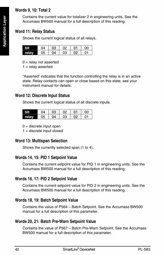
Word 11: Relay StatusShows the current logical status of all relays.
bit 04 03 02 01 00relay 05 04 03 02 01
0 = relay not asserted1 = relay asserted
“Asserted” indicates that the function controlling the relay is in an activestate. Relay contacts can open or close based on this state, see yourinstrument manual for details.
Word 12: Discrete Input StatusShows the current logical status of all discrete inputs.
bit 04 03 02 01 00relay 05 04 03 02 01
0 = discrete input open1 = discrete input closed
Word 13: Multispan SelectionShows the currently selected span (1 to 4).
Words 14, 15: PID 1 Setpoint ValueContains the current setpoint value for PID 1 in engineering units. See theAccumass BW500 manual for a full description of this reading.
Words 16, 17: PID 2 Setpoint ValueContains the current setpoint value for PID 2 in engineering units. See theAccumass BW500 manual for a full description of this reading.
Words 18, 19: Batch Setpoint ValueContains the value of P564 – Batch Setpoint. See the Accumass BW500manual for a full description of this parameter.
Words 20, 21: Batch Pre-Warn Setpoint ValueContains the value of P567 – Batch Pre-Warn Setpoint. See the AccumassBW500 manual for a full description of this parameter.
PL-583 SmartLinx® DeviceNet 43
Ap
plicatio
n L
ayer
Words 22 to 24: Parameter Number / Primary Index / Secondary Index, SPAThese words contain the last values written to words 0 to 2 of the write area.They confirm that the parameter value has been written. These words arenot updated until the value has been successfully transferred and stored inthe Milltronics SmartLinx instrument.
Words 25, 26: Value, SPAThe value of the specified parameter and index.
Word 27: Decimal Place, SPAThis word specifies the number of decimal places for the value in words25/26.
Positive values indicate that the decimal place shifts to the left.
i.e. A 1 means that all returned values have the decimal place shifted 1space to the left and a returned value of 5,213 is interpreted as 521.3.
Negative values indicate that the decimal place shifts to the right.
i.e. If this word is “-1”, a returned value of 5,213 is interpreted as 52,130.
Word 28: Format, SPAThis word is always 0.
Word 29: Read / Write Flag, SPAThis word mirrors the read/write word 7.
0 = read1 = write
Word 30: Word OrderThe placement of the most significant word (MSW).
0 = MSW first1 = MSW second
44 SmartLinx® DeviceNet PL-583
Ap
plic
atio
n L
ayer
Data TypesThe Milltronics SmartLinx instrument parameters take on many values invarious formats, as discussed in the Milltronics SmartLinx instrumentmanual. For the convenience of the programmer, those values are convertedto and from 16-bit integer numbers, since those are easily handled by mostPLCs.
Integer
Level ProductsInteger parameter values are by far the most common. For example,parameter P920 (Reading) returns a number representing the currentreading (either level or volume, depending on the Milltronics SmartLinxinstrument configuration).
Numeric values may be requested or set in units or percent of span, andmay be specified with a number of decimal places.
Numeric values must be in the range -20,000 to be +20,000 to be valid. If aparameter is requested and its value is more than +20,000, the number32,767 is returned; if it is less than -20,000, the number -32,768 is returned.If this happens, increase the number of decimal places for that parameter.
If a parameter cannot be expressed in terms of percent (e.g. span), or hasno meaningful value, the special number 22,222 is returned. Try requestingthe parameter in units, or refer to the Milltronics SmartLinx instrumentmanual to understand the format and use of the requested parameter.
Mass Dynamics ProductsIntegers used on the Mass Dynamics products can have any valid value. So,the entire range from -32,768 to 32,767 or 0 to 65,535 is available and novalues are used as error conditions.
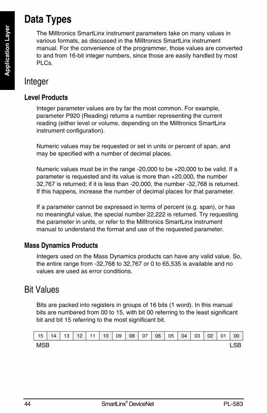
Bit Values
Bits are packed into registers in groups of 16 bits (1 word). In this manualbits are numbered from 00 to 15, with bit 00 referring to the least significantbit and bit 15 referring to the most significant bit.
15 14 13 12 11 10 09 08 07 06 05 04 03 02 01 00
MSB LSB
PL-583 SmartLinx® DeviceNet 45
Ap
plicatio
n L
ayer
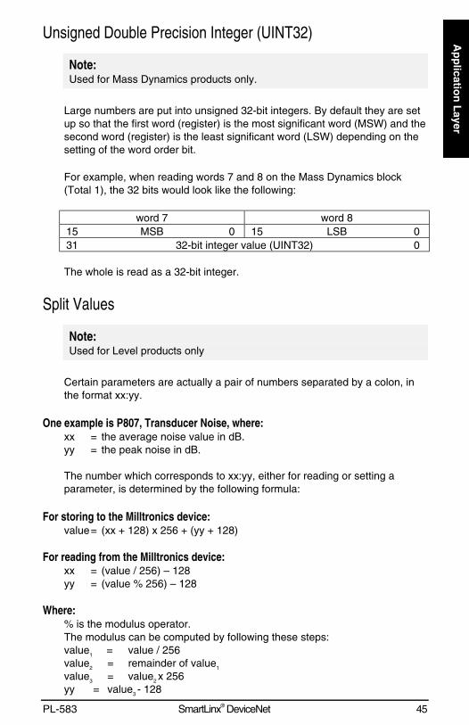
Unsigned Double Precision Integer (UINT32)
Note:Used for Mass Dynamics products only.
Large numbers are put into unsigned 32-bit integers. By default they are setup so that the first word (register) is the most significant word (MSW) and thesecond word (register) is the least significant word (LSW) depending on thesetting of the word order bit.
For example, when reading words 7 and 8 on the Mass Dynamics block(Total 1), the 32 bits would look like the following:
word 7 word 815 MSB 0 15 LSB 031 32-bit integer value (UINT32) 0
The whole is read as a 32-bit integer.
Split Values
Note:Used for Level products only
Certain parameters are actually a pair of numbers separated by a colon, inthe format xx:yy.
One example is P807, Transducer Noise, where:xx = the average noise value in dB.yy = the peak noise in dB.
The number which corresponds to xx:yy, either for reading or setting aparameter, is determined by the following formula:
For storing to the Milltronics device:value= (xx + 128) x 256 + (yy + 128)
For reading from the Milltronics device:xx = (value / 256) – 128yy = (value % 256) – 128
Where:% is the modulus operator.The modulus can be computed by following these steps:value1 = value / 256value2 = remainder of value1
value3 = value2 x 256yy = value3 - 128
46 SmartLinx® DeviceNet PL-583
Ap
plic
atio
n L
ayer
It may simplify programming to notice:xx = (most significant byte of value) – 128yy = (least significant byte of value) – 128
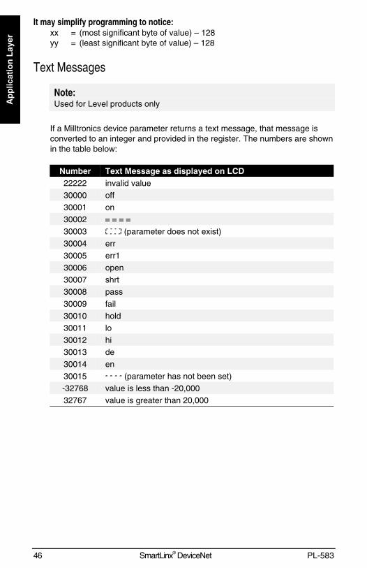
Text Messages
Note:Used for Level products only
If a Milltronics device parameter returns a text message, that message isconverted to an integer and provided in the register. The numbers are shownin the table below:
Number Text Message as displayed on LCD22222 invalid value30000 off30001 on30002 ≡ ≡ ≡ ≡30003 (parameter does not exist)30004 err30005 err130006 open30007 shrt30008 pass30009 fail30010 hold30011 lo30012 hi30013 de30014 en30015 (parameter has not been set)-32768 value is less than -20,00032767 value is greater than 20,000
PL-583 SmartLinx® DeviceNet 47
Ap
plicatio
n L
ayer
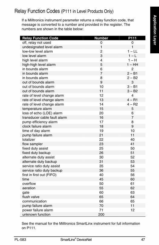
Relay Function Codes (P111 in Level Products Only)
If a Milltronics instrument parameter returns a relay function code, thatmessage is converted to a number and provided in the register. Thenumbers are shown in the table below:
Relay Function Code Number P111off, relay not used 0 0undesignated level alarm 1 1low-low level alarm 2 1 – LLlow level alarm 3 1 – Lhigh level alarm 4 1 – Hhigh-high level alarm 5 1 – HHin bounds alarm 6 2in bounds alarm 7 2 – B1in bounds alarm 8 2 – B2out of bounds alarm 9 3out of bounds alarm 10 3 – B1out of bounds alarm 11 3 – B2rate of level change alarm 12 4rate of level change alarm 13 4 – R1rate of level change alarm 14 4 – R2temperature alarm 15 5loss of echo (LOE) alarm 20 6transducer cable fault alarm 16 7pump efficiency alarm 17 8clock failure alarm 18 9time of day alarm 19 10pump failure alarm 21 11totalizer 22 40flow sampler 23 41fixed duty assist 25 50fixed duty backup 26 51alternate duty assist 30 52alternate duty backup 31 53service ratio duty assist 35 54service ratio duty backup 36 55first in first out (FIFO) 40 56time 45 60overflow 50 61aeration 55 62gate 60 63flush valve 65 64communication 66 65pump failure alarm 70 11power failure alarm 71 12unknown function 200
See the manual for the Milltronics SmartLinx instrument for full informationon P111.

48 SmartLinx® DeviceNet PL-583
Ap
plic
atio
n L
ayer
PL-583 SmartLinx® DeviceNet 49
Tro
ub
lesho
otin
g
Troubleshooting
GenerallyIn all cases, first check that the SmartLinx module has passed its on-goingbuilt-in self test (Milltronics SmartLinx instrument parameter P790). Theresult should be “pass”.
If “fail” is indicated, either the module is defective, or the module connectoron the Milltronics SmartLinx instrument is defective.
If “err1” is indicated, the Milltronics software doesn’t recognize the installedmodule. Please contact Milltronics or your distributor for instructions and/orupgraded Milltronics SmartLinx instrument software.
Make sure the Milltronics instrument is set to a unique address, and does notconflict with any other slave(s) on the bus.
Check the configuration of the scanning master, and make sure it isfunctioning properly.
If an AiRanger is being used, check P795 to make sure that it is equal to 24(DeviceNet module). If this parameter is showing any other number then youhave the wrong SmartLinx card.
Specifically
1. The card passes the built in self test, but will not connect to thenetwork.
• Check to make sure P751, P752 are set correctly and that you do nothave another instrument on the LAN with the same MAC ID.
• Check to make sure all 8 DIP switches are set correctly.
• Check the wiring to the card (or terminal strips)
2. The lights on the card indicate that it is OK and communicating, but Icannot see any data in the PLC.
• When you configured your master, did you map the data into the M files(AB only) and did you add code to the PLC you access then.
• Some Device net scanners have a control word where you can place thescanner in Ideal Mode. Check that your scanner is in Run mode.

50 SmartLinx® DeviceNet PL-583
Tro
ub
lesh
oo
tin
g
PL-583 SmartLinx® DeviceNet 51
Ind
ex
IndexAbout this Manual… ..............................7About this Module… ..............................8Accumass BW 500..............................10
data map .........................................36AiRanger Series ....................................9
connection.......................................11Alarm and Status.................................34Application Layer.................................19Audience ...............................................7Batch Prewarn Setpoint ......................39Batch Pre-Warn Setpoint Value ..........42Batch Setpoint.....................................39Batch Setpoint Value...........................42Baud rate (P751).................................17Bit Values ............................................44Cable
connector ........................................11Card Type .................. See Module TypeCommand Control, Operational
Commands .....................................37Communication parameters ................16Communication Setup.........................15Compatibility..........................................9Compatible Devices ..............................5Configuration Status............................41CraneRanger.........................................9
connection.......................................11Data Access Methods .........................20Data Map
Accumass BW 500..........................36EnviroRanger ..................................30level products..................................24
Data Types..........................................44Bit Values........................................44integer .............................................44Numeric...........................................44P111 Values....................................47Split Values .....................................45text messages.................................46UINT32............................................45
Decimal Place25, 26, 28, 29, 31, 32, 34,35, 37, 43
Devicecompatibility ......................................9
Device Type ........................................15DeviceNet..............................................7DIP Switches.......................................11Direct Access ......................................21Discrete Input Status...........................42EDS Files ............................................16EnviroRanger ......................................10EnviroRanger ERS 500
connection.......................................11
Factory setting ....................................17Flag.....................................................35Format.......25, 28, 29, 31, 32, 35, 37, 43Freeze.................................................38Index ...................................................35
alarm and status .............................34MPA................................................21point reading.............................28, 34primary............................................19secondary .......................................20SPA.................................................23
Indexed Parameters ...........................19Installation.............................................9Instrument Status................................40Integer.................................................44InterRanger DPS 300 ...........................9
connection ......................................11LEDs ...................................................13Level Products ......................................9
data map...................................24, 30Load....................................................41Mark ..................... See Secondary IndexMass Dynamics
data map.........................................36Master Reset ......................................19Measurement Point Status ...........27, 33Module Type
Accumass BW 500 .........................10AiRanger Series ...............................9CraneRanger ....................................9EnviroRanger..................................10InterRanger DPS 300 .......................9
MPAoverview .........................................21parameter indexing.........................21using ...............................................21
Multiple Parameter Access ......See MPAMultispan Selection.......................39, 42Numeric Values ..................................44Operating Mode ............................26, 32Operation ............................................13P751....................................................17P752....................................................17P999....................................................19Parameter ...............................25, 31, 36
writing in block ................................23Parameter Indexes .............................19Parameter Number25, 28, 29, 31, 35, 43Parameter Number and Secondary
Index...............................................35Parameter Secondary Index...25, 28, 31Parameters .........................................16PID 1 Setpoint Value ..........................42
52 SmartLinx® DeviceNet PL-583
Ind
exPID 2 Setpoint Value...........................42PID Mode ............................................38PID Setpoints ......................................39PID Status ...........................................41Point ....................35. See Primary IndexPoint Alarm and Status .......................34Point Reading............................... 28, 34Point-on-Priority ........................... 24, 30Primary Index . 19, 21, 25, 29, 31, 36, 43Print .....................................................39Print Status..........................................41Product code .......................................15Program Mode ....................................41Rate.....................................................41Read
mass dynamics products ................39read/write flag......................................29Read/Write Flag ............... 26, 32, 37, 43Reading........................................ 28, 34
EnviroRanger ..................................33level products..................................27MPA ................................................21SPA.................................................22
Relay Function Codes.........................47Relay Status........................................42Resistor
termination ......................................11Returned Values .......................... 28, 34Run Mode Types.................................20Secondary Index20, 22, 26, 29, 32, 36,
43Setpoint Source...................................38Setup Procedure .................................16Single Parameter Access.........See SPASPA
overview..........................................22parameter indexing .........................23
reading............................................22using ...............................................22writing .............................................23
Span....................................................38Span Status ........................................41Specifications........................................5Speed..................................................41Split Values.........................................45Status..................................................13Terminal Block
connector........................................11Termination Switch .............................11Text Messages ...................................46Total 1 .................................................41Total 2 .................................................42Totalizer Reset....................................38Totalizer Status...................................41Totalizing Status .................................41Troubleshooting ..................................49UINT32................................................45Unsigned Double Precision Integer ....45Using
MPA................................................21SPA.................................................22
Value.....................26, 29, 32, 35, 36, 43Vendor ID............................................16Wiring
connector........................................11Word Order ...................................39, 43Write
mass dynamics products ................36Write Privileges...................................41Writing.................................................23
EnviroRanger..................................30level products .................................24
Zero.....................................................38Zero Status .........................................41

*7ml19981BH01*


