Convenient pluggable wiring terminals; accepts up to 14 AWG wire
Powered by a single 5-volt supply
Channel-specific LEDs
Operating temperature: 0 to 70 °C
UL and CE approved (most modules); Factory Mutual approved (part numbers ending in FM)
Description
Opto 22 SNAP I/O digital output modules are part of the SNAP PAC System.
Customers can choose from AC or DC models. Optical isolation on all solid-state modules provides 4,000 volts of transient (4000 V for 1 ms) protection for sensitive control electronics from industrial field signals.
All SNAP digital modules have removable top-mounted connectors to provide easy access for field wiring. All operate on 5 VDC control logic. Each digital module features integral channel-specific LEDs for convenient troubleshooting and maintenance.
Each module is factory tested twice before shipment, and most modules are UL and CE approved. In addition, part numbers ending in FM are Factory Mutual approved.
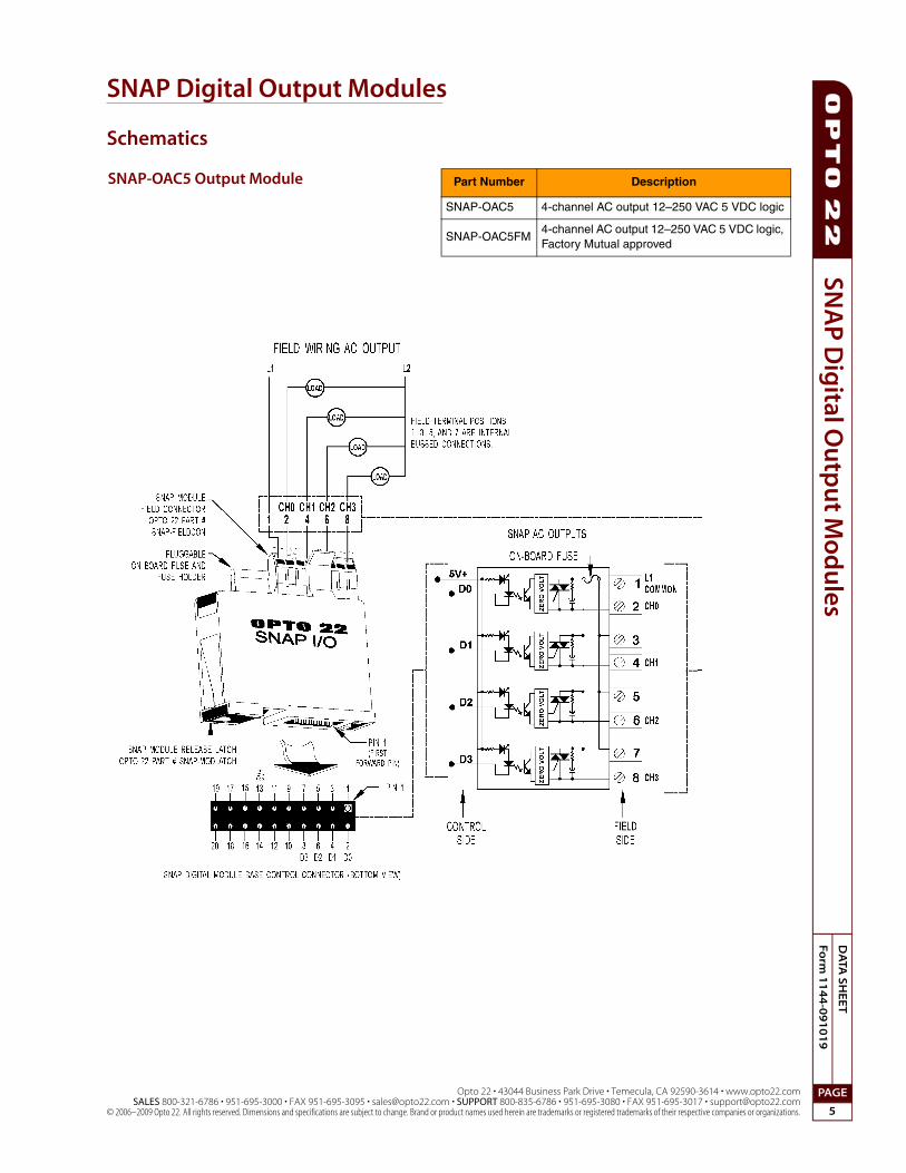
SNAP output modules are used to switch up to four separate AC or DC loads. Output modules that are fused use a standard fuse with a convenient handle for easy replacement. DC outputs are available in either a source or sink configuration. AC outputs are zero voltage turn on and zero current turn off for transient-free switching.
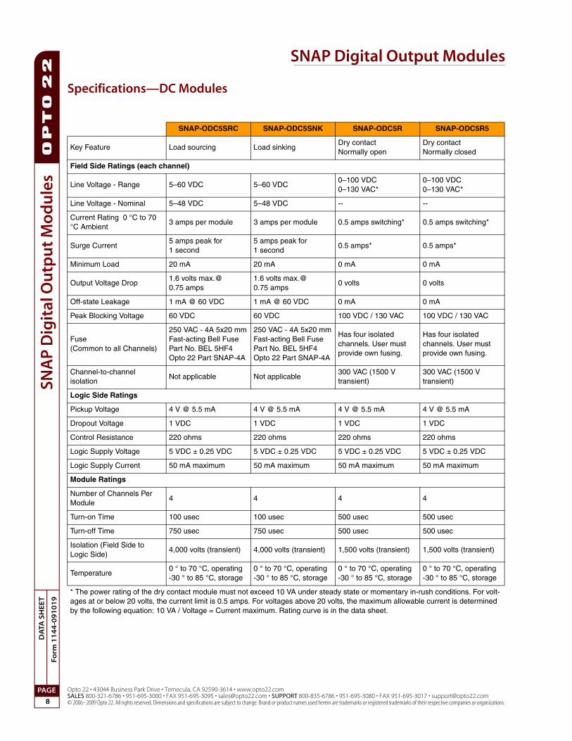
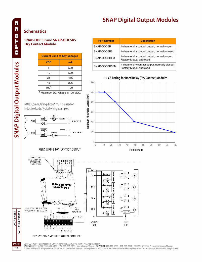
The dry contact modules allow switching of low power signals where signal integrity must be maintained, or where
zero leakage current is a requirement. Dry contact modules are not solid-state devices. They use reed relays, which are electromechanical devices. These modules do not provide optical isolation. Current rating for dry contact modules depends on the voltage they are used with, as shown in the graph on page 14.
SNAP-OAC5MA and SNAP-ODC5MA are special modules featuring manual-on/manual-off/automatic switches, ideal for diagnostic testing of control applications. The switches override output from the application, so you can quickly check field device wiring. These modules each contain four isolated channels.
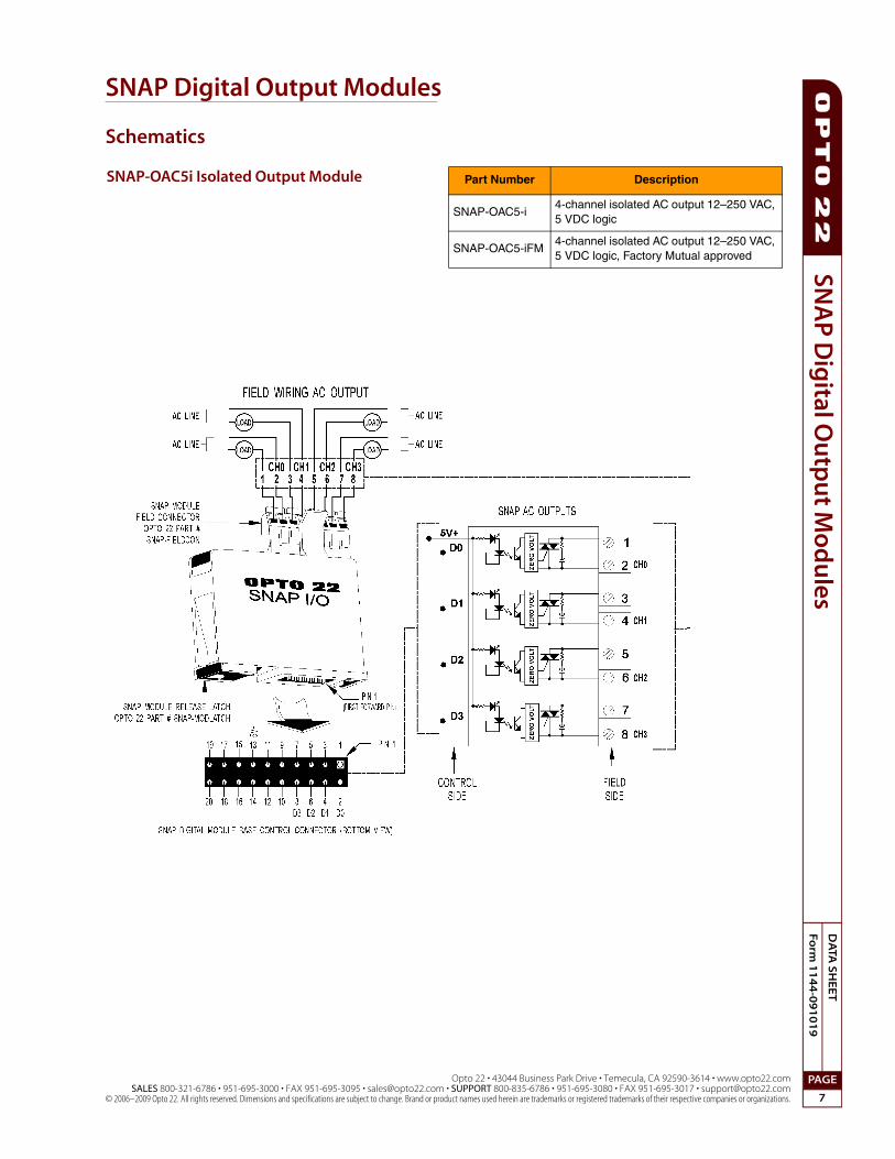
The SNAP-OAC5-i, SNAP-ODC5-i, and SNAP-ODC5A-i modules provide four isolated output channels.
For Ethernet-based applications requiring higher density of digital I/O points, see Opto 22 form #1556, the SNAP High-Density Digital Module Data Sheet.
I/O Processor Compatibility
SNAP digital output modules are compatible with all SNAP PAC brains and rack-mounted controllers, including both standard wired models and Wired+Wireless™ models.
Notes for legacy hardware: SNAP digital output modules are also compatible with SNAP Ultimate, SNAP Ethernet, and SNAP Simple brains, as well as other SNAP brains such as the serial B3000 and the B3000HA. These modules can be used on B-series and M-series mounting racks.
Installation
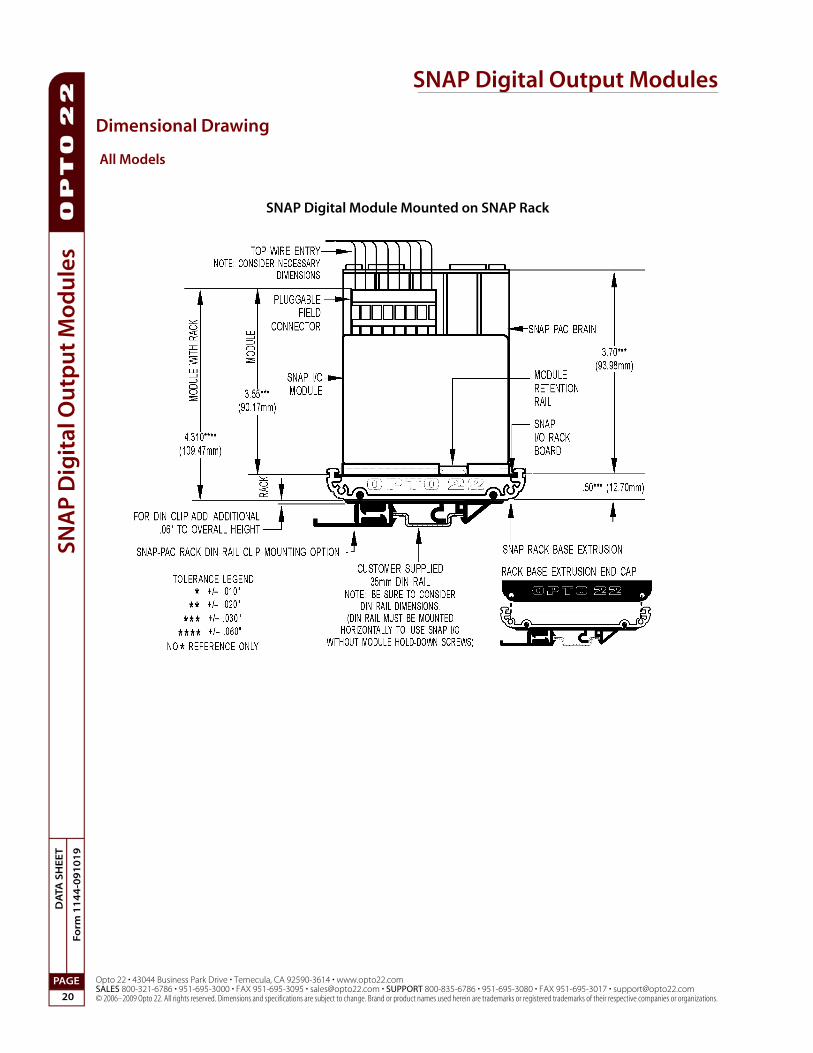
The following diagram shows part of a SNAP mounting rack. The rack is shown without screw connectors.
Modules snap securely into place in the row of connectors on the rack. Each module connector has a number. Digital output modules and other types of SNAP I/O modules are mounted on the module connectors starting at module position zero.
NOTE: Check the data sheet or user’s guide for the brain or on-the-rack controller you are using to determine module features available and any restrictions on module placement.
1. Place the rack so that the module connector numbers are right-side up, with zero on the left, as shown in the diagram above. (If your rack has screw connectors, the screw connectors will be at the bottom.)
2. Position the module over the module connector, aligning the small slot at the base of the module with the retention bar on the rack. When positioning modules next to each other, be sure to align the male and female module keys at the tops of the modules before snapping a module into position.
3. With the module correctly aligned, push on the module to snap it into place.
4. (Optional) Use standard 4-40 x 1/2 truss-head Phillips hold-down screws to secure both sides of each module. CAUTION: Do not over-tighten screws.
5. Follow the wiring diagrams beginning on page 5 to attach modules to the devices they monitor.
Modules require a special tool (provided) for removal.
Module position zero
Module connectors Processor connector Retention bar
SNAP Digital Output Modules
Opto 22 • 43044 Business Park Drive • Temecula, CA 92590-3614 • www.opto22.comSALES 800-321-6786 • 951-695-3000 • FAX 951-695-3095 • [email protected] • SUPPORT 800-835-6786 • 951-695-3080 • FAX 951-695-3017 • [email protected]
Temperature0 ° to 70 °C, operating-30 ° to 85 °C, storage
0 ° to 70 °C, operating-30 ° to 85 °C, storage
0 ° to 70 °C, operating-30 ° to 85 °C, storage
0 ° to 70 °C, operating-30 ° to 85 °C, storage
* The power rating of the dry contact module must not exceed 10 VA under steady state or momentary in-rush conditions. For volt-ages at or below 20 volts, the current limit is 0.5 amps. For voltages above 20 volts, the maximum allowable current is determined by the following equation: 10 VA / Voltage = Current maximum. Rating curve is in the data sheet.
SNAP Digital Output Modules
Opto 22 • 43044 Business Park Drive • Temecula, CA 92590-3614 • www.opto22.comSALES 800-321-6786 • 951-695-3000 • FAX 951-695-3095 • [email protected] • SUPPORT 800-835-6786 • 951-695-3080 • FAX 951-695-3017 • [email protected]
Temperature0 ° to 70 °C, operating-30 ° to 85 °C, storage
0 ° to 70 °C, operating-30 ° to 85 °C, storage
0 ° to 70 °C, operating-30 ° to 85 °C, storage
0 ° to 70 °C, operating-30 ° to 85 °C, storage
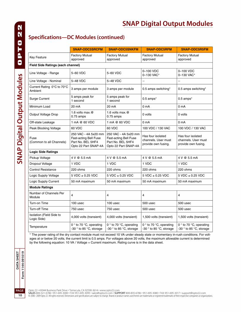
* The power rating of the dry contact module must not exceed 10 VA under steady state or momentary in-rush conditions. For volt-ages at or below 20 volts, the current limit is 0.5 amps. For voltages above 20 volts, the maximum allowable current is determined by the following equation: 10 VA / Voltage = Current maximum. Rating curve is in the data sheet.
SNAP Digital Output Modules
Opto 22 • 43044 Business Park Drive • Temecula, CA 92590-3614 • www.opto22.comSALES 800-321-6786 • 951-695-3000 • FAX 951-695-3095 • [email protected] • SUPPORT 800-835-6786 • 951-695-3080 • FAX 951-695-3017 • [email protected]
IMPORTANT: The mounting rack connector has 24 pins; the module connector has 20 pins. The extra pins on the mounting rack connector prevent misalignment of the module during installation.
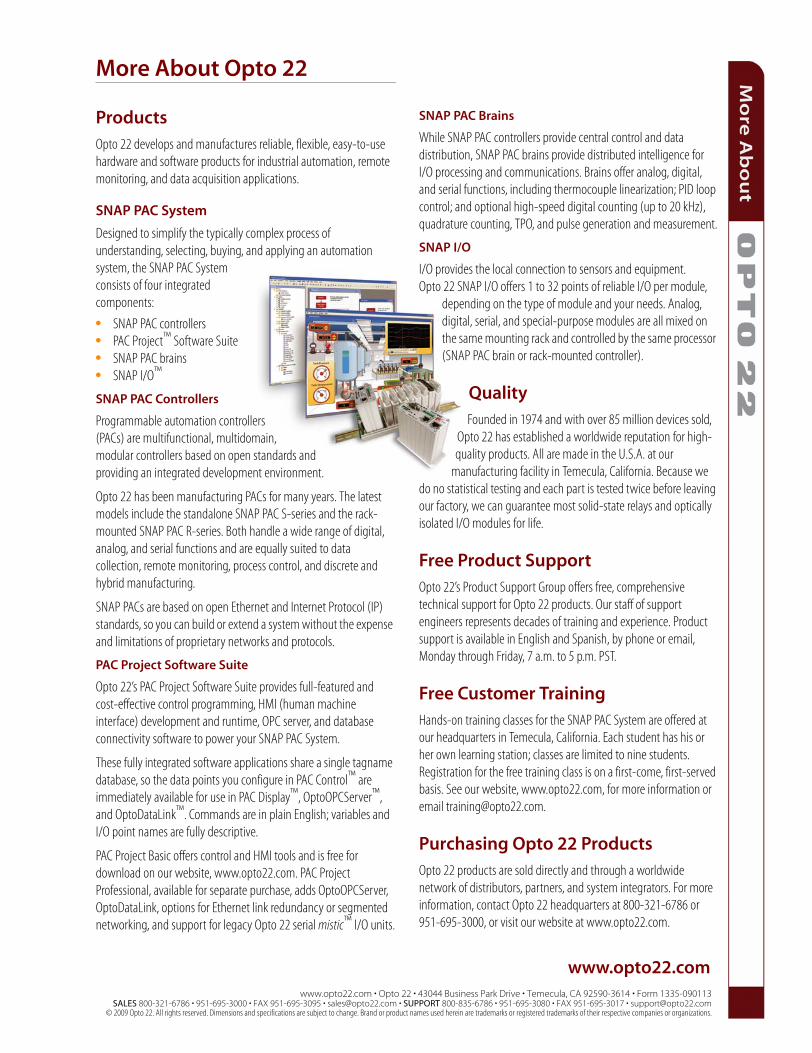
ProductsOpto 22 develops and manufactures reliable, flexible, easy-to-use hardware and software products for industrial automation, remote monitoring, and data acquisition applications.
SNAP PAC System
Designed to simplify the typically complex process of understanding, selecting, buying, and applying an automation system, the SNAP PAC System consists of four integrated components:
Programmable automation controllers (PACs) are multifunctional, multidomain, modular controllers based on open standards and providing an integrated development environment.
Opto 22 has been manufacturing PACs for many years. The latest models include the standalone SNAP PAC S-series and the rack-mounted SNAP PAC R-series. Both handle a wide range of digital, analog, and serial functions and are equally suited to data collection, remote monitoring, process control, and discrete and hybrid manufacturing.
SNAP PACs are based on open Ethernet and Internet Protocol (IP) standards, so you can build or extend a system without the expense and limitations of proprietary networks and protocols.
PAC Project Software Suite
Opto 22’s PAC Project Software Suite provides full-featured and cost-effective control programming, HMI (human machine interface) development and runtime, OPC server, and database connectivity software to power your SNAP PAC System.
These fully integrated software applications share a single tagname database, so the data points you configure in PAC Control™ are immediately available for use in PAC Display™, OptoOPCServer™, and OptoDataLink™. Commands are in plain English; variables and I/O point names are fully descriptive.
PAC Project Basic offers control and HMI tools and is free for download on our website, www.opto22.com. PAC Project Professional, available for separate purchase, adds OptoOPCServer, OptoDataLink, options for Ethernet link redundancy or segmented networking, and support for legacy Opto 22 serial mistic™ I/O units.
SNAP PAC Brains
While SNAP PAC controllers provide central control and data distribution, SNAP PAC brains provide distributed intelligence for I/O processing and communications. Brains offer analog, digital, and serial functions, including thermocouple linearization; PID loop control; and optional high-speed digital counting (up to 20 kHz), quadrature counting, TPO, and pulse generation and measurement.
SNAP I/O
I/O provides the local connection to sensors and equipment. Opto 22 SNAP I/O offers 1 to 32 points of reliable I/O per module,
depending on the type of module and your needs. Analog, digital, serial, and special-purpose modules are all mixed on the same mounting rack and controlled by the same processor (SNAP PAC brain or rack-mounted controller).
QualityFounded in 1974 and with over 85 million devices sold,
Opto 22 has established a worldwide reputation for high-quality products. All are made in the U.S.A. at our
manufacturing facility in Temecula, California. Because we do no statistical testing and each part is tested twice before leaving our factory, we can guarantee most solid-state relays and optically isolated I/O modules for life.
Free Product SupportOpto 22’s Product Support Group offers free, comprehensive technical support for Opto 22 products. Our staff of support engineers represents decades of training and experience. Product support is available in English and Spanish, by phone or email, Monday through Friday, 7 a.m. to 5 p.m. PST.
Free Customer TrainingHands-on training classes for the SNAP PAC System are offered at our headquarters in Temecula, California. Each student has his or her own learning station; classes are limited to nine students. Registration for the free training class is on a first-come, first-served basis. See our website, www.opto22.com, for more information or email [email protected].
Purchasing Opto 22 ProductsOpto 22 products are sold directly and through a worldwide network of distributors, partners, and system integrators. For more information, contact Opto 22 headquarters at 800-321-6786 or 951-695-3000, or visit our website at www.opto22.com.