Software Architecture for Computer Vision: Beyond Pipes and Filters Alexandre R.J. Fran¸cois Institute for Robotics and Intelligent Systems University of Southern California [email protected]July 2003 Abstract This document highlights and addresses architecture level software development issues facing re- searchers and practitioners in the field of Computer Vision. A new framework, or architectural style, called SAI, is introduced. It provides a formalism for the design, implementation and analysis of software systems that perform distributed parallel processing of generic data streams. Architectural patterns are illustrated with a number of demonstration projects ranging from single stream automatic real-time video processing to fully integrated distributed interactive systems mixing live video, graphics and sound. SAI is supported by an open source architectural middleware called MFSM. 1 Introduction 1.1 Motivation The emergence of comprehensive code libraries in a research field is a sign that researchers and practitioners are seriously considering and addressing software engineering and development issues. In this sense, the introduction of the Intel OpenCV library [2] certainly represents an important milestone for Computer Vision. The motivation behind building and maintaining code libraries is to address reusability and efficiency, by providing a set of “standard” data structures and implementations of classic algorithms. In a field like Computer Vision, with a rich theoretical history, implementation issues are often regarded as secondary to the pure research components outside of specialty subfields, such as Real-Time Computer Vision (see e.g. [27]). Nevertheless, beyond reducing development and debugging time, good code design and reusability are key to such fundamental principles of scientific research as experiment reproducibility and objective comparison with the existing state of the art. For example, these issues are apparent in the subfield of video processing/analysis, which, due to the conjunction of technical advances in various enabling hardware performance (including processors, cameras and storage media) and high priority application domains(e.g. visual surveillance [3]), has recently become a major area of research. One of the most spectacular side effects of this activity is the amount of test data generated, an important part of which is made public. The field has become so rich in analysis techniques that any new method must almost imperatively be compared to the state-of the art in its class to be seriously considered by the community. Reference data sets, complete with ground truth data, have been produced and compiled for this very purpose (see e.g. [6, 7, 8, 9]). Similarly, a reliable, reusable and consistent body of code for established–and “challenger”–algorithms could certainly facilitate the performance comparison task. Some effort is made toward developing open platforms for evaluation (see e.g. [19]). Such properties as modularity contribute to code reuse, and fair and consistent testing and comparison. However, building a platform generic enough to not only accommodate current methods, but also allow to incorporate other relevant algorithms, some of them not yet developed, is a major challenge. It is well known in the software industry that introducing features that were not planned for at design time in a software system is a least an extremely hard problem, and generally a recipe for disaster. Software Engineering is the field of study devoted to addressing these and other issues of software development in industrial settings. The parameters and constraints of industrial software development are certainly very different of that encountered in a research environment, and thus Software Engineering techniques are often unadapted to the latter. 1
Transcript
Software Architecture for Computer Vision:
Beyond Pipes and Filters
Alexandre R.J. FrancoisInstitute for Robotics and Intelligent Systems
This document highlights and addresses architecture level software development issues facing re-searchers and practitioners in the field of Computer Vision. A new framework, or architectural style,called SAI, is introduced. It provides a formalism for the design, implementation and analysis of softwaresystems that perform distributed parallel processing of generic data streams. Architectural patterns areillustrated with a number of demonstration projects ranging from single stream automatic real-time videoprocessing to fully integrated distributed interactive systems mixing live video, graphics and sound. SAIis supported by an open source architectural middleware called MFSM.
1 Introduction
1.1 Motivation
The emergence of comprehensive code libraries in a research field is a sign that researchers and practitionersare seriously considering and addressing software engineering and development issues. In this sense, theintroduction of the Intel OpenCV library [2] certainly represents an important milestone for Computer Vision.The motivation behind building and maintaining code libraries is to address reusability and efficiency, byproviding a set of “standard” data structures and implementations of classic algorithms. In a field likeComputer Vision, with a rich theoretical history, implementation issues are often regarded as secondary tothe pure research components outside of specialty subfields, such as Real-Time Computer Vision (see e.g.[27]). Nevertheless, beyond reducing development and debugging time, good code design and reusabilityare key to such fundamental principles of scientific research as experiment reproducibility and objectivecomparison with the existing state of the art.
For example, these issues are apparent in the subfield of video processing/analysis, which, due to theconjunction of technical advances in various enabling hardware performance (including processors, camerasand storage media) and high priority application domains(e.g. visual surveillance [3]), has recently becomea major area of research. One of the most spectacular side effects of this activity is the amount of test datagenerated, an important part of which is made public. The field has become so rich in analysis techniquesthat any new method must almost imperatively be compared to the state-of the art in its class to be seriouslyconsidered by the community. Reference data sets, complete with ground truth data, have been producedand compiled for this very purpose (see e.g. [6, 7, 8, 9]). Similarly, a reliable, reusable and consistent bodyof code for established–and “challenger”–algorithms could certainly facilitate the performance comparisontask. Some effort is made toward developing open platforms for evaluation (see e.g. [19]). Such propertiesas modularity contribute to code reuse, and fair and consistent testing and comparison. However, buildinga platform generic enough to not only accommodate current methods, but also allow to incorporate otherrelevant algorithms, some of them not yet developed, is a major challenge. It is well known in the softwareindustry that introducing features that were not planned for at design time in a software system is a leastan extremely hard problem, and generally a recipe for disaster. Software Engineering is the field of studydevoted to addressing these and other issues of software development in industrial settings. The parametersand constraints of industrial software development are certainly very different of that encountered in aresearch environment, and thus Software Engineering techniques are often unadapted to the latter.
In a research environment, software is developed to demonstrate the validity and evaluate the performanceof an algorithm. The main performance aspect on which algorithms are evaluated is of course the accuracyof their output. Another aspect of performance is measured in terms of system throughput, or algorithmexecution time. This aspect is all the more relevant as the amount of data to be processed increases, leavingless and less time for storing and off-line processing. The metrics used for this type of performance assessmentare often partial. In particular, theoretical complexity analysis is but a prediction tool, which cannot accountfor the many other factors involved in a particular system’s performance. Many algorithms are claimed tobe “real-time.” Some run at a few frames per second, but “could be implemented to run in real-time,”or simply will run faster on the next generation machines (or the next...). Others have been the object ofcareful design and specialization to allow a high processing rate on constrained equipment. The generalbelief that increasing computing power can make any system (hardware and software) run faster relies onthe hidden or implied assumption of system scalability, a property that cannot and should not be taken forgranted. Indeed, the performance of any given algorithm implementation is highly dependent on the overallsoftware system in which it is operated (see e.g. [20]). Video analysis applications commonly involve imageinput (from file or camera) and output (to file or display) code, the performance of which can greatly impactthe perceived performance of the overall application, and in some cases the performance of the individualalgorithms involved in the processing. Ideally, if an algorithm or technique is relevant for a given purpose,it should be used in its best available implementation, on the best available platform, with the opportunityof upgrading either when possible.
As Computer Vision is maturing as a field, and finds new applications in a variety of domains, the issueof interoperability becomes central to its successful integration as an enabling technology in cross-disciplinaryefforts. Technology transfer from research to industry could also be facilitated by the adoption of relevantmethodologies in the development of research code.
If these aspects are somewhat touched in the design of software libraries, a consistent, generic approachrequires a higher level of abstraction. This is the realm of Software Architecture, the field of study concernedwith the design, analysis and implementation of software systems. Shaw and Garlan give the followingdefinition in [26]:
“As the size and complexity of software systems increase, the design and specification of overallsystem structure become more significant issues than the choice of algorithms and data structuresof computation. Structural issues include the organization of a system as a composition ofcomponents; global control structures; the protocols for communication, synchronization and dataaccess; the assignment of functionality to design elements; the composition of design elements;physical distribution; scaling and performance; dimensions of evolution; and selection amongdesign alternatives. This is the Software Architecture level of design.”
They also provide the framework for architecture description and analysis used in the remainder of thisdocument. A specific architecture can be described as a set of computational components, and a theirinter-relations, or connectors. An architectural style characterizes families of architectures that share somepatterns of structural organization. Formally, an architectural style defines a vocabulary of components andconnector types, and a set of constraints on how instances of these types can be combined to form a validarchitecture.
If Software Architecture is a relatively young field, software architectures have been developed sincethe first software was designed. Classic styles have been identified and studied informally and formally,their strengths and shortcomings analyzed. A major challenge for the software architect is the choice of anappropriate style when designing a given system, as an architectural style may be ideal for some applications,while unadapted for others. The goal here is to help answer this question by providing the Computer Visioncommunity with a flexible and generic architectural model. The first step toward the choice–or the design–ofan architectural style is the identification and formulation of the core requirements for the target system(s).An appropriate style should support the design and implementation of software systems capable of handlingimages, 2-D and 3-D geometric models, video streams, various data structures, in a variety of algorithmsand computational frameworks. These applications may be interactive and/or have real-time constraints.Going beyond pure Computer Vision systems, processing of other data types, such as sound and hapticsdata, should also be supported, in a consistent manner, in order to compose large scale integrated systems,such as immersive simulations. Note that interaction has a very particular status in this context, as dataoriginating from the user can be both an input to an interactive Computer Vision system, and the outputof a vision-based perceptual interface subsystem.
This set of requirements can be captured under the general definition of cross-disciplinary dynamicsystems, possibly involving real-time constraints, user immersion and interaction. A fundamental underlyingcomputational invariant across such systems is distributed parallel processing of generic data-streams. Asno existing architectural model could entirely and satisfactorily account for such systems, a new model wasintroduced.
1.2 Contribution
SAI (Software Architecture for Immersipresence) is a new software architecture model for designing, analyz-ing and implementing applications performing distributed, asynchronous parallel processing of generic datastreams. The goal of SAI is to provide a universal framework for the distributed implementation of algo-rithms and their easy integration into complex systems that exhibit desirable software engineering qualitiessuch as efficiency, scalability, extensibility, reusability and interoperability. SAI specifies a new architecturalstyle (components, connectors and constraints). The underlying extensible data model and hybrid (sharedrepository and message-passing) distributed asynchronous parallel processing model allow natural and effi-cient manipulation of generic data streams, using existing libraries or native code alike. The modularity ofthe style facilitates distributed code development, testing, and reuse, as well as fast system design and inte-gration, maintenance and evolution. A graph-based notation for architectural designs allows intuitive systemrepresentation at the conceptual and logical levels, while at the same time mapping closely to processes.
MFSM (Modular Flow Scheduling Middleware) [12] is an architectural middleware implementing the SAIstyle. Its core element, the FSF library, is a set of extensible classes that can be specialized to define newdata structures and processes, or encapsulate existing ones (e.g. from libraries). MFSM is an open sourceproject, released under the GNU Lesser General Public License [1]. A number of software modules regroupspecializations implementing specific algorithms or functionalities. They constitute a constantly growingbase of open source, reusable code, maintained as part of the MFSM project. The project also includesextensive documentation, including user guide, reference guide and tutorials.
1.3 Outline
This document is a an introduction to SAI, oriented toward Computer Vision. Section 2 identifies architec-tural principles for distributed parallel processing of generic data streams. The most common architecturalstyles for data stream processing applications are derived from the classic Pipes and Filters model. It is, forexample, the underlying model of the Microsoft DirectShow library, part of the DirectX suite [24]. After abrief review of the Pipes and Filters architectural style, of its strengths and weaknesses, a new hybrid modelis introduced, that addresses the identified limitations while preserving the desirable properties. Section 3formally defines the new model as the SAI architectural style. Its component and connector types are defined,together with the corresponding constraints on instances interaction. The underlying data and processingmodels are explicited and analyzed. Simultaneously, graphical symbols are introduced to represent eachelement type. Together these symbols constitute a graph-based notation system for representing architec-tural designs. Section 4 illustrates architectural patterns with a number of demonstration projects rangingfrom single stream automatic real-time video processing to fully integrated distributed interactive systemsmixing live video, graphics and sound. Section 5 offers a summary of relevant architectural properties of thisnew style. Section 6 gives a brief overview of MFSM. In conclusion, Section 7 offers a summary and someperspectives on future directions for SAI.
2 Beyond Pipes and Filters
The Pipes and Filters model is an established (and popular) model for data stream manipulation andprocessing architectures. In particular, it is a classic model in the domains of signal processing, parallelprocessing and distributed processing [10], to name but a few. This section first offers an overview of theclassic Pipes and Filters architectural style, emphasizing its desirable properties, and highlighting its mainlimitations. A hybrid model is then outlined, that aims at addressing the limitations while preserving thedesirable properties.
In the Pipes and Filters architectural style, the components, called filters have a set of inputs and a setof outputs. Each component reads (and consumes) a stream of data on its input and produces a streamof data on its output. The processing will usually be defined so that the component processes its inputincrementally, so that it can starts producing an output stream before it is finished receiving the totality ofits input stream, hence the name filter. The connectors are pipes in which the output stream of a filter flowsto the input of the next filter. Filters can be characterized by their input/output behavior: source filtersproduce a stream without any input; transform filters consume an input stream and produce an outputstream; sink filters consume an input stream but do not produce any output. Figure 1 presents an overview.Filters must be strictly independent entities: they do not share state information with other filters, the onlycommunication between filters occurs through the pipes. Furthermore, a filter’s specification might includerestrictions about its input and output streams, but it may not identify its upstream and downstream filters.These rules make the model highly modular. A more complete overview can be found in [26], includingpointers to in-depth studies of the classic style and its variations and specializations.
The Pipes and Filters style has a number of good properties that make it an attractive and efficientmodel for a number of applications. It is relatively simple to describe, understand and implement. It is alsoquite intuitive, and allows to model systems while preserving the flow of data. Some interesting propertiesresult from the modularity of the model. Because of the well-defined and constrained interaction modalitiesbetween filters, complex systems described in terms of data streams flowing from filter to filter are easilyunderstandable as a series of well defined local transformations. The implementation details of each filterare irrelevant to the high level understanding of the overall system, as long as a logical definition of theirbehavior is specified (input, transformation and output). The localization and isolation of computationsfacilitates system design, implementation, maintenance and evolution. Reversely, filters can be implementedand tested separately. Furthermore, because filters are independent, the model naturally supports paralleland distributed processing.
These properties of the model provide an answer to some of the software issues highlighted in the intro-duction. Because of their independence, filters certainly allow reusability and interoperability. Parallelismand distributability, to a certain extent, should contribute to efficiency and scalability. It would seem thatit is a perfect model for real-time, distributed parallel processing of data streams. However, a few keyshortcomings and limitations make it unsuitable for designing cross-disciplinary dynamic systems, possiblyinvolving real-time constraints, user immersion and interaction.
The first set of limitations is related to efficiency. If the pipes are first-in-first-out buffers, as suggested bythe model, the overall throughput of a Pipes and Filters system is imposed by the transmission rate of theslowest filter in the system. If filters independence provide a natural design for parallel (and/or distributed)processing, the pipes impose arbitrary transmission bottlenecks that make the model non optimal. Figure 2illustrates inefficiency limitations inherent to the distribution and transmission of data in Pipes and Filtersmodels. Each filter’s output data must be copied to its downstream filter(s)’ input, which can lead tomassive and expensive data copying. Furthermore, the model does not provide any consistent mechanism tomaintain correspondences between separate but related streams (e.g. when the results of different processpaths must be combined to produce a composite output). Such stream synchronization operations requiredata collection from different repositories, possibly throughout the whole system, raising not only search-related efficiency issues, but also dependency-driven distributed buffer maintenance issues. These can onlybe solved at the price of breaking the strict filter independence rule, e.g. by the introduction of a higher
Figure 2: Distributed parallel processing of data streams with the Pipes and Filters model.
level system manager.The second set of limitations is related to the simplicity of the model. As they are not part of the data
streams, process parameters (state data stored in the filters) are not modeled consistently with process data(input data streams). As a result, the pure Pipes and Filters model is ill-suited for designing interactivesystems, which can only be done at the price of increased filter complexity, and deviations from some of thewell-defined constraints that make for the model’s attractive simplicity. For example, a common practice forinteraction in Pipes and Filters systems is to provide access to the parameters (possibly at run-time) through“control panels.” This solution however necessitates a separate mechanism for processing and applying theinteraction data. This is for example the solution adopted in Microsoft’s DirectShow, which relies on theMicrosoft Windows message-based graphical interface for parameter access. Such external solutions howeveronly bypass, and do not address, the fundamental inability of the style to consistently model general feed-back loops, i.e. subsystems in which some processes are affected by some other processes’ outputs. This is adirect result of the strict communication rules between filters, and in particular of the constraint that filtersnot share any state information. Yet feed-back loops are a common pattern in dynamic systems, includinginteractive systems: interaction is indeed a processing loop in which a user is involved (as illustrated insection 4).
A careful consideration of system requirements in the target context of applicability guided a re-evaluationof the Pipes and Filters model, and the formulation of modified constraints that preserve the positive aspectswhile addressing the limitations identified above. Note that other properties were also considered, that areout of the scope of this document (e.g. run-time system evolution). These will only be mentioned whenrelevant in the remainder of this document.
2.2 A hybrid model
A few key observations, resulting from the analysis of system requirements for real-time interactive, immersiveapplications, allow to formulate principles and concepts that address the shortcomings identified above.Figure 3 offers a synopsis.
2.2.1 Time
A critical underlying concept in all user-related application domains (but by no means limited to thesedomain) is that of time. Whether implicitly or explicitly modeled, time relations and ordering are inherentproperties of any sensory-related data stream (e.g. image streams, sound, haptics, etc.), absolutely necessarywhen users are involved in the system, even if not on-line or in real-time. Users perceive data as streams ofdynamic information, i.e. evolving in time. This information only makes sense if synchronization constraintsare respected within each stream (temporal precedence) and across streams (precedence and simultaneity).It follows that time information is a fundamental attribute of all process data, and should therefore beexplicitly modeled both in data structures and in processes.
Synchronization is a fundamental operation in temporal data stream manipulation systems. It shouldtherefore also be an explicit element of the architectural model. A structure called pulse is introduced to
Figure 3: A hybrid shared repository and message passing model for distributed parallel processing of datastreams.
regroup synchronous data. Data streams are thus quantized temporally (not necessarily uniformly). Asopposed to the Pipes and Filters case, where data remains localized in the filters where it is created or used,it is grouped in pulses, which flow from processing center to processing center along streams. The processingcenters do not consume their input, but merely use it to produce some output that is added to the pulse.This also reduces the amount of costly data copy: in a subgraph implemented on a platform with sharedmemory space, only a pointer to the evolving pulse structure will be transmitted from processing center toprocessing center. Note that such processing centers can no longer be called filters.
2.2.2 Parallelism
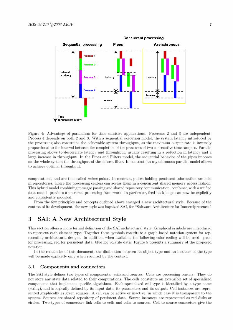
Figure 4 illustrates system latency, which is the overall computation time for an input sample, and throughputor output rate, inverse of the time elapsed between two consecutive output samples. The goal for high qualityinteraction is to minimize system latency and maximize system throughput. In the sequential executionmodel, latency and throughput are directly proportional. In powerful computers, this usually results in thelatency dictating the system throughput as well, which is arguably the worst possible case. In the Pipesand Filters model, filters can run in parallel. Latency and throughput are thus independent. Because of theparallelism, system latency can be reduced in most cases with careful design, while system throughput willalmost always be greatly improved. The sequential behavior of the pipes, however, imposes on the wholesystem the throughput of the slowest filter. This constraint can actually be relaxed to yield an asynchronousparallel processing model. Instead of being held in a buffer to be processed by order of arrival, each incomingpulse is processed on arrival in the processing center, in a separate thread. Achievable throughput is nowoptimal. It will actually be achieved if no hardware or software resources become exhausted (e.g. computingpower, memory, bus bandwidth, etc.). Of course, an asynchronous model requires to explicitly implementsynchronization when necessary, but only then.
2.2.3 Data classes
The Pipes and Filters model explicitly separates data streams and process parameters, which is both avalid functional distinction, and a source of inconsistency in the model, leading to important limitationsas explained above. A re-consideration of this categorization, in the context of temporal data streamsprocessing, reveals two distinct data classes: volatile and persistent.
Volatile data is used, produced and/or consumed, and remains in the system only for a limited fractionof its lifetime. For example, in a video processing application, the video frames captured and processedare typically volatile data: after they have been processed and displayed or saved, they are not kept in thesystem. Process parameters, on the other hand, must remain in the system for the whole duration of itsactivity. Note that their value can change in time. They are dynamic yet persistent data.
All data, volatile or persistent, should be encapsulated in pulses. Pulses holding volatile data flow downstreams defined by connections between the processing centers, in a message passing fashion. They trigger
Figure 4: Advantage of parallelism for time sensitive applications. Processes 2 and 3 are independent;Process 4 depends on both 2 and 3. With a sequential execution model, the system latency introduced bythe processing also constrains the achievable system throughput, as the maximum output rate is inverselyproportional to the interval between the completion of the processes of two consecutive time samples. Parallelprocessing allows to decorrelate latency and throughput, usually resulting in a reduction in latency and alarge increase in throughput. In the Pipes and Filters model, the sequential behavior of the pipes imposeson the whole system the throughput of the slowest filter. In contrast, an asynchronous parallel model allowsto achieve optimal throughput.
computations, and are thus called active pulses. In contrast, pulses holding persistent information are heldin repositories, where the processing centers can access them in a concurrent shared memory access fashion.This hybrid model combining message passing and shared repository communication, combined with a unifieddata model, provides a universal processing framework. In particular, feed-back loops can now be explicitlyand consistently modeled.
From the few principles and concepts outlined above emerged a new architectural style. Because of thecontext of its development, the new style was baptized SAI, for “Software Architecture for Immersipresence.”
3 SAI: A New Architectural Style
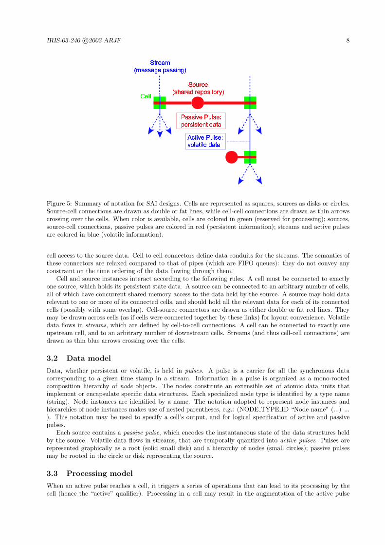
This section offers a more formal definition of the SAI architectural style. Graphical symbols are introducedto represent each element type. Together these symbols constitute a graph-based notation system for rep-resenting architectural designs. In addition, when available, the following color coding will be used: greenfor processing, red for persistent data, blue for volatile data. Figure 5 presents a summary of the proposednotation.
In the remainder of this document, the distinction between an object type and an instance of the typewill be made explicitly only when required by the context.
3.1 Components and connectors
The SAI style defines two types of components: cells and sources. Cells are processing centers. They donot store any state data related to their computations. The cells constitute an extensible set of specializedcomponents that implement specific algorithms. Each specialized cell type is identified by a type name(string), and is logically defined by its input data, its parameters and its output. Cell instances are repre-sented graphically as green squares. A cell can be active or inactive, in which case it is transparent to thesystem. Sources are shared repository of persistent data. Source instances are represented as red disks orcircles. Two types of connectors link cells to cells and cells to sources. Cell to source connectors give the
Figure 5: Summary of notation for SAI designs. Cells are represented as squares, sources as disks or circles.Source-cell connections are drawn as double or fat lines, while cell-cell connections are drawn as thin arrowscrossing over the cells. When color is available, cells are colored in green (reserved for processing); sources,source-cell connections, passive pulses are colored in red (persistent information); streams and active pulsesare colored in blue (volatile information).
cell access to the source data. Cell to cell connectors define data conduits for the streams. The semantics ofthese connectors are relaxed compared to that of pipes (which are FIFO queues): they do not convey anyconstraint on the time ordering of the data flowing through them.
Cell and source instances interact according to the following rules. A cell must be connected to exactlyone source, which holds its persistent state data. A source can be connected to an arbitrary number of cells,all of which have concurrent shared memory access to the data held by the source. A source may hold datarelevant to one or more of its connected cells, and should hold all the relevant data for each of its connectedcells (possibly with some overlap). Cell-source connectors are drawn as either double or fat red lines. Theymay be drawn across cells (as if cells were connected together by these links) for layout convenience. Volatiledata flows in streams, which are defined by cell-to-cell connections. A cell can be connected to exactly oneupstream cell, and to an arbitrary number of downstream cells. Streams (and thus cell-cell connections) aredrawn as thin blue arrows crossing over the cells.
3.2 Data model
Data, whether persistent or volatile, is held in pulses. A pulse is a carrier for all the synchronous datacorresponding to a given time stamp in a stream. Information in a pulse is organized as a mono-rootedcomposition hierarchy of node objects. The nodes constitute an extensible set of atomic data units thatimplement or encapsulate specific data structures. Each specialized node type is identified by a type name(string). Node instances are identified by a name. The notation adopted to represent node instances andhierarchies of node instances makes use of nested parentheses, e.g.: (NODE TYPE ID “Node name” (...) ...). This notation may be used to specify a cell’s output, and for logical specification of active and passivepulses.
Each source contains a passive pulse, which encodes the instantaneous state of the data structures heldby the source. Volatile data flows in streams, that are temporally quantized into active pulses. Pulses arerepresented graphically as a root (solid small disk) and a hierarchy of nodes (small circles); passive pulsesmay be rooted in the circle or disk representing the source.
3.3 Processing model
When an active pulse reaches a cell, it triggers a series of operations that can lead to its processing by thecell (hence the “active” qualifier). Processing in a cell may result in the augmentation of the active pulse
Figure 6: Pulse filtering. Each cell is associated with its required volatile and persistent data structures,in the form of substructures called active and passive filters (respectively). Pulses are searched for thesestructures in an operation called filtering, which results in the creation of handles that can be used duringprocessing for direct access to relevant nodes.
(input data), and/or update of the passive pulse (process parameters). The processing of active pulses iscarried in parallel, as they are received by the cell. Since a cell process can only read the existing data inan active pulse, and never modify it (except for adding new nodes), concurrent read access will not requireany special precautions. In the case of passive pulses, however, appropriate locking (e.g. through criticalsections) must be implemented to avoid inconsistencies in concurrent shared memory read/write access.
3.4 Dynamic data binding
Passive pulses may hold persistent data relevant to several cells. Therefore, before a cell can be activated,the passive pulse must be searched for the relevant persistent data. As data is accumulated in active pulsesflowing down the streams through cells, it is also necessary for a cell to search each active pulse for its inputdata. If the data is not found, or if the cell is not active, the pulse is transmitted, as is, to the connecteddownstream cells. If the input data is found, then the cell process is triggered. When the processing iscomplete, then the pulse, which now also contains the output data, is passed downstream.
Searching a pulse for relevant data, called filtering, is an example of run-time data binding. The targetdata is characterized by its structure: node instances (type and name) and their relationships. The structureis specified as a filter or a composition hierarchy of filters. Note that the term filter is used here in its “sieving”sense. Figure 6 illustrates this concept. A filter is an object that specifies a node type, a node name or namepattern and eventual subfilters corresponding to subnodes. The filter composition hierarchy is isomorphicto its target node structure. The filtering operation takes as input a pulse and a filter, and, when successful,returns a handle or hierarchy of handles isomorphic to the filter structure. Each handle is essentially apointer to the node instance target of the corresponding filter. When relevant, optional names inheritedfrom the filters allow to identify individual handles with respect to their original filters.
The notation adopted for specifying filters and hierarchies of filters is nested square brackets. Each filterspecifies a node type, a node instance name or name pattern (with wildcard characters), an optional handlename, and an eventual list of subfilters, e.g.: [NODE TYPE ID “Node name” handle id [...] ... ]. Optionalfilters are indicated by a star, e.g.: [NODE TYPE ID “Node name” handle id]*.
When several targets in a pulse match a filter name pattern, all corresponding handles are created. Thisallows to design processes whose input (parameters or stream data) number is not fixed. If the root of theactive filter specifies a pattern, the process method is invoked for each handle generated by the filtering(sequentially, in the same thread). If the root of the passive filter specifies a pattern, only one passive handlewill be generated (pointing to the first encountered node satisfying the pattern).
3.5 Architectural design specification
A particular system architecture is specified at the conceptual level by a set of source and cell instances, andtheir inter-connections. Specialized cells may be accompanied by a description of the task they implement.Source and cell instances may be given names for easy reference. In some cases, important data nodes and
outputs may be specified schematically to emphasize some design aspects. Section 4 contains several exampleconceptual graphs for various systems.
A logical level description of a design requires to specify, for each cell, its active and passive filters and itsoutput structure, and for each source, the structure of its passive pulse. Table 1 summarizes the notationsfor logical level cell definition. Filters and nodes are described using the nested square brackets and nestedparentheses notations introduced above. By convention, in the cell output specification, (x) represents thepulse’s root, (.) represents the node corresponding to the root of the active filter, and (..) represents itsparent node.
ClassName CELL TYPE ID(ParentClass)Active filter [NODE TYPE ID “Node name” handle id
[...] ... ]Passive filter [NODE TYPE ID “Node name” handle id
[...] ... ]Output (NODE TYPE ID
“default output base name–more if needed”(...) ... )
Table 1: Notations for logical cell definition.
4 Example Designs
Architectural patterns are now illustrated with demonstration projects ranging from single stream, automaticreal-time video processing to fully integrated distributed interactive systems mixing live video, graphics andsound. The projects are tentatively presented in order of increasing complexity, interactivity and cross-disciplinary integration. Each project is briefly introduced, its software architecture described and analyzed.Key architectural patterns, of general interest, are highlighted. These include feed-back loops, real-timeincremental processing along the time dimension, interaction loops, real-time distributed processing, mixingand synchronization of multiple independent data streams.
4.1 Real-time video segmentation and tracking
The development of real-time video analysis applications was actually a steering concern during the devel-opment of the SAI style. The system presented here was used as a testbed for the implementation, testingand refinement of some SAI concepts [18].
The video analysis tasks performed are low level segmentation and blob tracking. The segmentation isperformed by change detection using an adaptive statistical color background model (the camera is assumedstationary). A review of background maintenance algorithms can be found in [28]. Blob tracking is performedusing a new multiresolution algrithm whose description is out of the scope of this document.
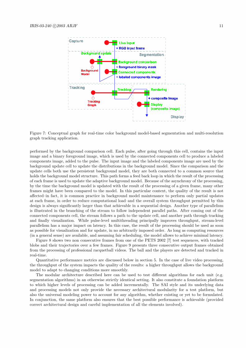
Figure 7 shows the conceptual level architecture of the software system. It is build around a single streamgoing through a number of cells. The graph can be decomposed into four functional subgraphs: capture,segmentation, tracking, visualization. The stream originates in the video input cell, which produces, at agiven rate, pulses containing an image coming either from a live capture device or a video file. This cell andits source constitute the capture unit of the application. The stream then goes through the segmentationunit, which is analyzed below. Coming out of the segmentation, the stream goes through a tracking cell.The result visualization unit is composed of a rendering and a display subunits. Rendering of a persistentstructure (here, the tracking graph) will be illustrated in a more general context in another example below(“Live Video in Animated 3-D Graphics”). The display cell simply puts on the screen its input images, inthis case the composite frames produced by the renderer.
A very interesting aspect of this system, and certainly the most innovative when it was introduced, isthe asynchronous parallel implementation of the segmentation algorithm, which contains a feed-back loop.The corresponding conceptual graph is also a flow graph of the algorithm. Each input frame is comparedwith a statistical background model. For each pixel, a decision is made whether it is an observation ofthe background or of an occluding element. The output is a foreground binary mask. This comparison is
Figure 7: Conceptual graph for real-time color background model-based segmentation and multi-resolutiongraph tracking application.
performed by the background comparison cell. Each pulse, after going through this cell, contains the inputimage and a binary foreground image, which is used by the connected components cell to produce a labeledcomponents image, added to the pulse. The input image and the labeled components image are used by thebackground update cell to update the distributions in the background model. Since the comparison and theupdate cells both use the persistent background model, they are both connected to a common source thatholds the background model structure. This path forms a feed back loop in which the result of the processingof each frame is used to update the adaptive background model. Because of the asynchrony of the processing,by the time the background model is updated with the result of the processing of a given frame, many otherframes might have been compared to the model. In this particular context, the quality of the result is notaffected–in fact, it is common practice in background model maintenance to perform only partial updatesat each frame, in order to reduce computational load–and the overall system throughput permitted by thisdesign is always significantly larger than that achievable in a sequential design. Another type of parallelismis illustrated in the branching of the stream to follow independent parallel paths. After coming out of theconnected components cell, the stream follows a path to the update cell, and another path through trackingand finally visualization. While pulse-level multithreading principally improves throughput, stream-levelparallelism has a major impact on latency. In this case, the result of the processing should be used as soonas possible for visualization and for update, in no arbitrarily imposed order. As long as computing resources(in a general sense) are available, and assuming fair scheduling, the model allows to achieve minimal latency.
Figure 8 shows two non consecutive frames from one of the PETS 2002 [7] test sequences, with trackedblobs and their trajectories over a few frames. Figure 9 presents three consecutive output frames obtainedfrom the processing of professional racquetball videos. The ball and the players are detected and tracked inreal-time.
Quantitative performance metrics are discussed below in section 5. In the case of live video processing,the throughput of the system impacts the quality of the results: a higher throughput allows the backgroundmodel to adapt to changing conditions more smoothly.
The modular architecture described here can be used to test different algorithms for each unit (e.g.segmentation algorithms) in an otherwise strictly identical setting. It also constitute a foundation platformto which higher levels of processing can be added incrementally. The SAI style and its underlying dataand processing models not only provide the necessary architectural modularity for a test platform, butalso the universal modeling power to account for any algorithm, whether existing or yet to be formulated.In conjunction, the same platform also ensures that the best possible performance is achievable (providedcorrect architectural design and careful implementation of all the elements involved).
Figure 8: Object segmentation and tracking results in a PETS02 test sequence. The examples shown aretwo sample output composite frames taken at different times in the original video.
Figure 9: Segmentation and tracking of the players and the ball in professional racquetball video. Theexamples shown are three consecutive output composite frames.
4.2 Real-time video painting
The Video Painting project was developed as a demonstration of the real-time video stream processing abilityprovided by the SAI architectural style. It also provided valuable insight on the design and implementationof algorithms performing incremental processing along the time dimension, i.e. between different samples ina same stream.
The technical core of the application is a feature-based, multi-resolution scheme to estimate frame toframe projective or affine transforms [21]. These transforms are used to warp the frames to a common spaceto form a mosaic. The mosaic image itself is a persistent structure that evolves as more images are processed,hence the name “video painting.”
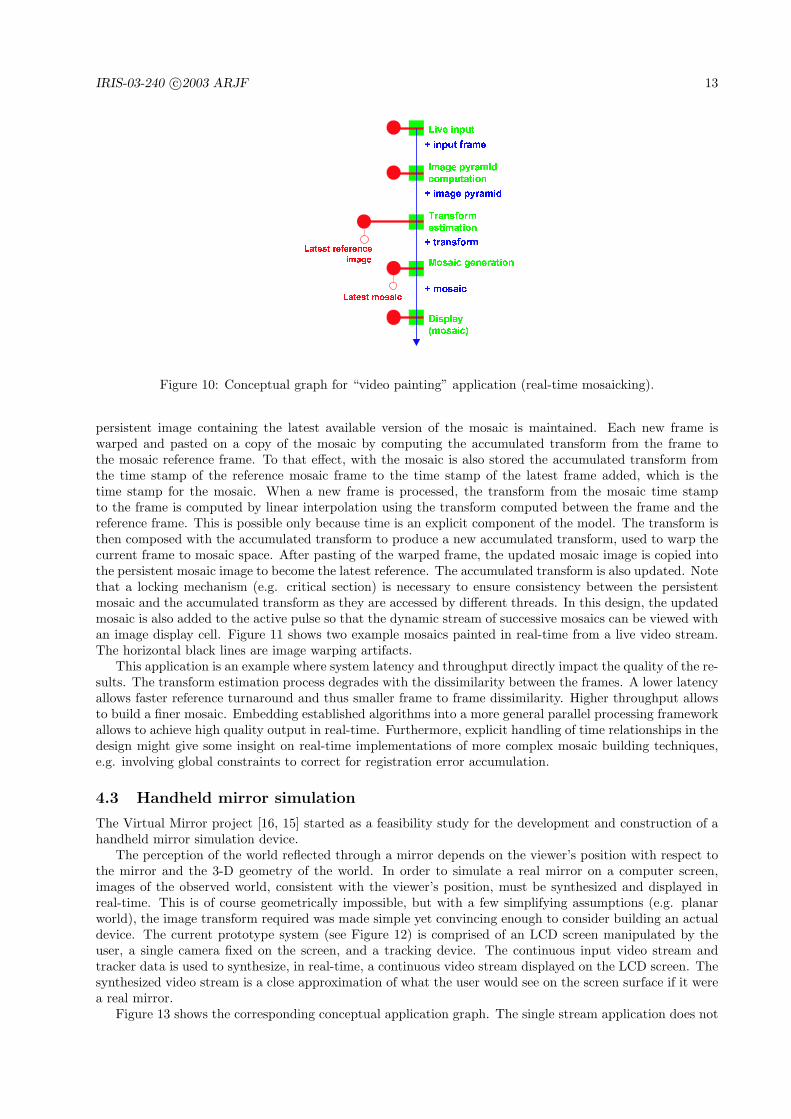
In a traditional sequential system, the transform between each pair of consecutive frames would becomputed, and each frame would be added to the mosaic by combination of all the transforms between areference frame and the current frame. Figure 10 shows the application graph for the SAI design. A liveinput unit creates the single stream, with frames captured from a camera. A simple cell computes the imagepyramid associated with each input frame, and necessary for the multi-resolution frame-to-frame transformestimation performed by the next downstream cell. Comparing two samples of the same stream requiresto make one persistent, which becomes the reference. Transforms are thus computed between the currentframe and a reference frame. For the algorithm to work properly, though, the compared frames cannot betoo far apart. The reference frame must therefore be updated constantly. Because of the asynchrony of theprocessing, the reference frame is not necessarily the frame “right before” the current frame in the stream.The simplistic handling of frames relationships in the sequential model is no longer sufficient. Accurate timestamps allow a more general approach to the problem. The transforms computed between two frames are nolonger implicitly assumed to relate two consecutive frames, separated from a fixed time interval, but betweentwo frames of arbitrary time stamps. For efficiency reasons, the mosaic is also computed incrementally. A
Figure 10: Conceptual graph for “video painting” application (real-time mosaicking).
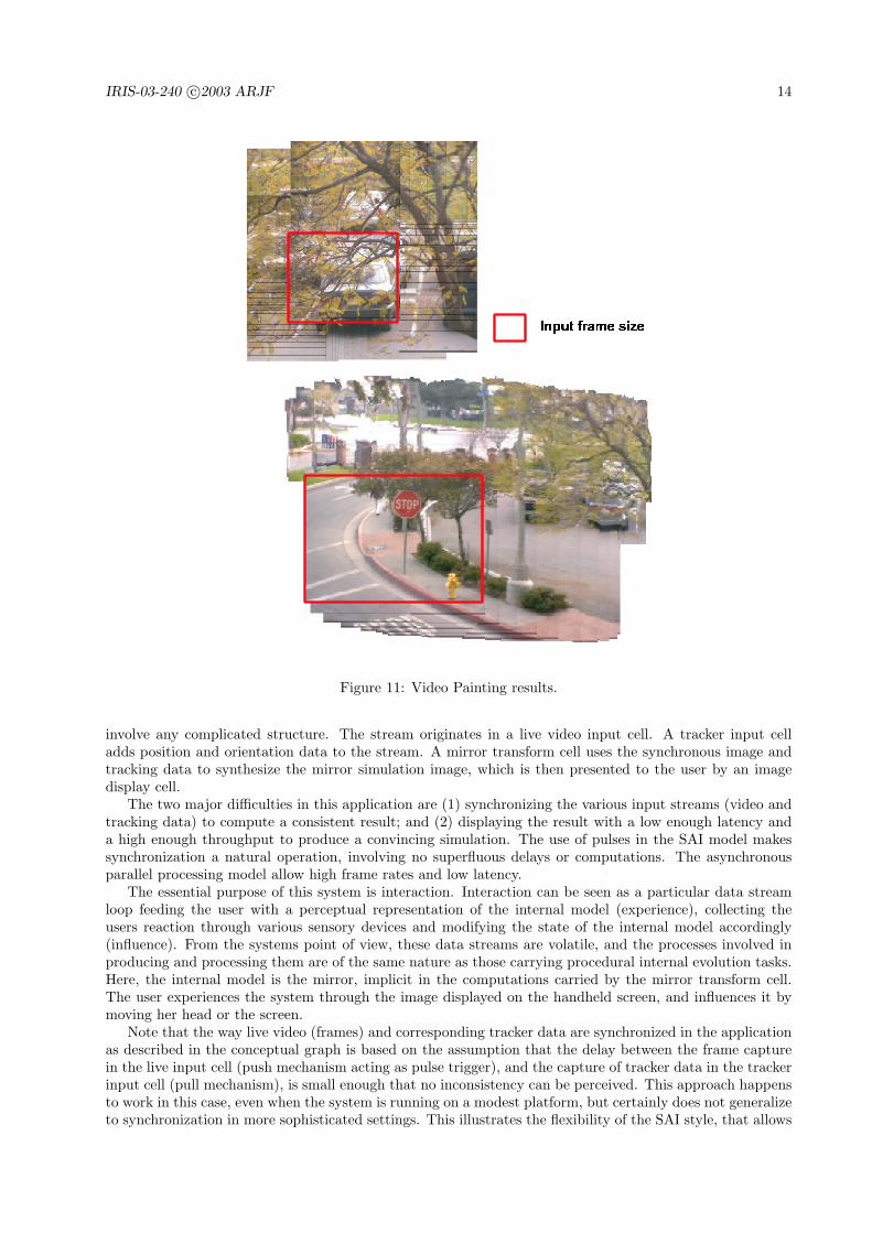
persistent image containing the latest available version of the mosaic is maintained. Each new frame iswarped and pasted on a copy of the mosaic by computing the accumulated transform from the frame tothe mosaic reference frame. To that effect, with the mosaic is also stored the accumulated transform fromthe time stamp of the reference mosaic frame to the time stamp of the latest frame added, which is thetime stamp for the mosaic. When a new frame is processed, the transform from the mosaic time stampto the frame is computed by linear interpolation using the transform computed between the frame and thereference frame. This is possible only because time is an explicit component of the model. The transform isthen composed with the accumulated transform to produce a new accumulated transform, used to warp thecurrent frame to mosaic space. After pasting of the warped frame, the updated mosaic image is copied intothe persistent mosaic image to become the latest reference. The accumulated transform is also updated. Notethat a locking mechanism (e.g. critical section) is necessary to ensure consistency between the persistentmosaic and the accumulated transform as they are accessed by different threads. In this design, the updatedmosaic is also added to the active pulse so that the dynamic stream of successive mosaics can be viewed withan image display cell. Figure 11 shows two example mosaics painted in real-time from a live video stream.The horizontal black lines are image warping artifacts.
This application is an example where system latency and throughput directly impact the quality of the re-sults. The transform estimation process degrades with the dissimilarity between the frames. A lower latencyallows faster reference turnaround and thus smaller frame to frame dissimilarity. Higher throughput allowsto build a finer mosaic. Embedding established algorithms into a more general parallel processing frameworkallows to achieve high quality output in real-time. Furthermore, explicit handling of time relationships in thedesign might give some insight on real-time implementations of more complex mosaic building techniques,e.g. involving global constraints to correct for registration error accumulation.
4.3 Handheld mirror simulation
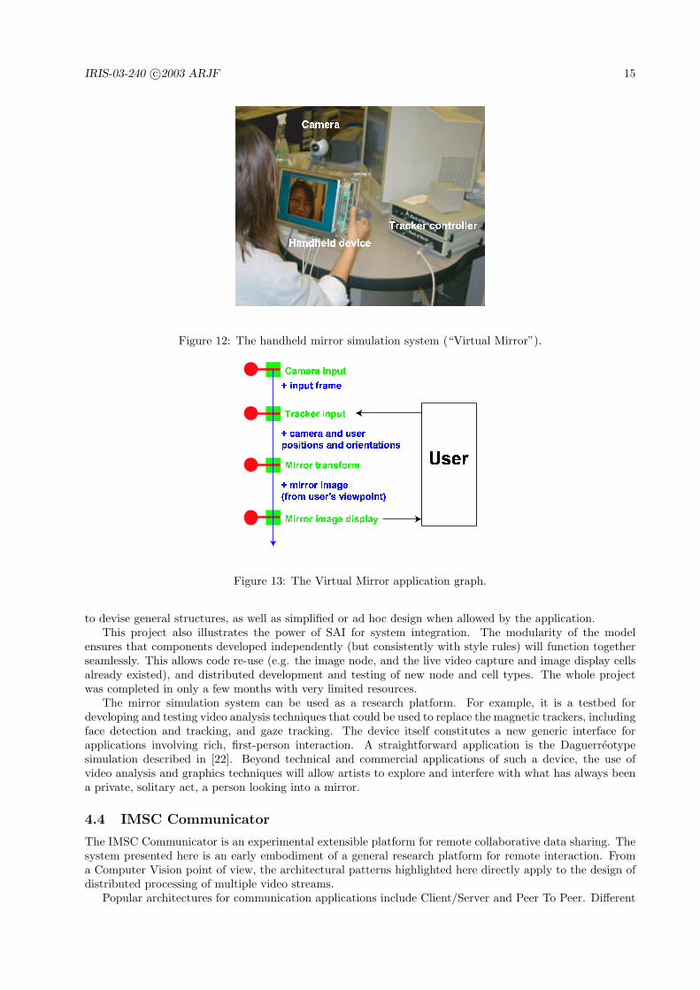
The Virtual Mirror project [16, 15] started as a feasibility study for the development and construction of ahandheld mirror simulation device.
The perception of the world reflected through a mirror depends on the viewer’s position with respect tothe mirror and the 3-D geometry of the world. In order to simulate a real mirror on a computer screen,images of the observed world, consistent with the viewer’s position, must be synthesized and displayed inreal-time. This is of course geometrically impossible, but with a few simplifying assumptions (e.g. planarworld), the image transform required was made simple yet convincing enough to consider building an actualdevice. The current prototype system (see Figure 12) is comprised of an LCD screen manipulated by theuser, a single camera fixed on the screen, and a tracking device. The continuous input video stream andtracker data is used to synthesize, in real-time, a continuous video stream displayed on the LCD screen. Thesynthesized video stream is a close approximation of what the user would see on the screen surface if it werea real mirror.
Figure 13 shows the corresponding conceptual application graph. The single stream application does not
involve any complicated structure. The stream originates in a live video input cell. A tracker input celladds position and orientation data to the stream. A mirror transform cell uses the synchronous image andtracking data to synthesize the mirror simulation image, which is then presented to the user by an imagedisplay cell.
The two major difficulties in this application are (1) synchronizing the various input streams (video andtracking data) to compute a consistent result; and (2) displaying the result with a low enough latency anda high enough throughput to produce a convincing simulation. The use of pulses in the SAI model makessynchronization a natural operation, involving no superfluous delays or computations. The asynchronousparallel processing model allow high frame rates and low latency.
The essential purpose of this system is interaction. Interaction can be seen as a particular data streamloop feeding the user with a perceptual representation of the internal model (experience), collecting theusers reaction through various sensory devices and modifying the state of the internal model accordingly(influence). From the systems point of view, these data streams are volatile, and the processes involved inproducing and processing them are of the same nature as those carrying procedural internal evolution tasks.Here, the internal model is the mirror, implicit in the computations carried by the mirror transform cell.The user experiences the system through the image displayed on the handheld screen, and influences it bymoving her head or the screen.
Note that the way live video (frames) and corresponding tracker data are synchronized in the applicationas described in the conceptual graph is based on the assumption that the delay between the frame capturein the live input cell (push mechanism acting as pulse trigger), and the capture of tracker data in the trackerinput cell (pull mechanism), is small enough that no inconsistency can be perceived. This approach happensto work in this case, even when the system is running on a modest platform, but certainly does not generalizeto synchronization in more sophisticated settings. This illustrates the flexibility of the SAI style, that allows
Figure 12: The handheld mirror simulation system (“Virtual Mirror”).
����������
����������
�������������
�����������������
����������
�����������������������������������
��������������������������������
����
Figure 13: The Virtual Mirror application graph.
to devise general structures, as well as simplified or ad hoc design when allowed by the application.This project also illustrates the power of SAI for system integration. The modularity of the model
ensures that components developed independently (but consistently with style rules) will function togetherseamlessly. This allows code re-use (e.g. the image node, and the live video capture and image display cellsalready existed), and distributed development and testing of new node and cell types. The whole projectwas completed in only a few months with very limited resources.
The mirror simulation system can be used as a research platform. For example, it is a testbed fordeveloping and testing video analysis techniques that could be used to replace the magnetic trackers, includingface detection and tracking, and gaze tracking. The device itself constitutes a new generic interface forapplications involving rich, first-person interaction. A straightforward application is the Daguerreotypesimulation described in [22]. Beyond technical and commercial applications of such a device, the use ofvideo analysis and graphics techniques will allow artists to explore and interfere with what has always beena private, solitary act, a person looking into a mirror.
4.4 IMSC Communicator
The IMSC Communicator is an experimental extensible platform for remote collaborative data sharing. Thesystem presented here is an early embodiment of a general research platform for remote interaction. Froma Computer Vision point of view, the architectural patterns highlighted here directly apply to the design ofdistributed processing of multiple video streams.
Popular architectures for communication applications include Client/Server and Peer To Peer. Different
Figure 14: Simple generic networking for distributed applications.
elements of the overall system are considered separate applications. Although these models can either beencapsulated or implemented in the SAI style, a communication application designed in the SAI style can alsobe considered as a single distributed application graph, in which some cell to cell connections are replacedwith network links. From this point of view, specific network architectures would be implemented in the SAIstyle, as part of the overall distributed application.
The core pattern of the Communicator is a sequence of cells introducing network communication betweentwo independent subgraphs. Figure 14 shows an example sequence comprising encoding, compression andnetworking (send) on the emitting side, networking (receive), decompression and decoding on the receivingside. The encoding cell flattens a node structure into a linear buffer so that the structure can later beregenerated. This encoding can be specific of various data types, as is the case for the example describedhere. A general encoding scheme could for example be based on XML. The output of an encoding cellis a character string (binary or text). The compression cell takes as input the encoded character string,and produces a compressed buffer. The compression scheme used can be input data dependent, or generic,in which case it should be lossless. For the first experiments, a simple compression cell, and matchingdecompression cell, were developed, that encapsulate the open source LZO library [25] for real-time losslesscompression/decompression. Note that the compression step is optional. The networking cells are responsiblefor packetizing and sending incoming character strings on one side, and receiving the packets and restoringthe string on the other side. Different modalities and protocols can be implemented and tested. The firstnetworking cells were implemented using Windows Sockets, using either TCP/IP or UDP. The decompressioncell regenerates the original character string from the compressed buffer. The decoding cell regenerates thenode structure into a pulse, from the encoded character string.
Once a generic platform is available for developing and testing data transfer modalities, support forvarious specific data types can be added. The very first test system supported video only, using existing livevideo capture and image display cells. For the next demonstration, a new live capture cell for both imageand sound was developed using Microsoft DirectShow [24]. Another new cell was developed for synchronizedrendering of sound and video, also using DirectShow.
Figure 15 shows the conceptual graph for an early embodiment of the 2-way communicator, with examplescreen shots. A background replacement unit, based on the segmentation by change detection presented abovein section 4.1, was added to the capture side to illustrate how the modularity of the architecture allows to“plug-and-play” subgraphs developed independently. Having different processing of video and sound alsodemonstrates the advantages of adopting an asynchronous model, and of performing synchronization onlywhen necessary, in this case in the display cell.
4.5 Live video in animated 3-D graphics
The example presented in this section is a real-time, interactive application requiring manipulation of het-erogenous data streams [14]. A video stream (captured live or read from a file) is used as surface texture onan animated 3-D model, rendered in real-time. The (virtual) camera used for rendering can be manipulated
Figure 15: Conceptual graph for an early version of the IMSC Communicator, with support for video(synchronized image and sound).
in real-time (e.g. with a gamepad or through a head tracking device), making the system interactive. Thissystem was developed to illustrate the design of a scene graph-based graphics toolkit, and the advantagesprovided by the SAI style for manipulating independently and synchronizing different data streams in acomplex interactive (possibly immersive) setting.
From a Computer Vision point of view, this example illustrates how the SAI style allows to manipulatevideo streams and geometric models in a consistent framework. The same architectural patterns generalizeto manipulating generic data streams and persistent models.
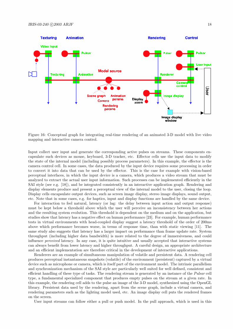
Figure 16 shows the system’s conceptual graph. The graph is composed of four functional subgraphs,corresponding to four independent streams, organized around a central source that holds the 3-D modelrepresentation in the form of a scene graph, and various process parameters for the different connected cells.The rendering stream generates images of the model. The control stream updates the (virtual) cameraposition based on user input. Together, the rendering and control units (including the shared source) forman interaction loop with the user. The animation stream drives the dynamic evolution of the 3-D model.The texturing stream places images captured from a video source (camera or file) in the texture node in thescene graph. Interaction and modeling are now analyzed in more detail.
4.5.1 Interaction
As observed above, interaction is a particular data stream loop feeding the user with a perceptual represen-tation of the internal model (experience), collecting the users reaction through various sensory devices andmodifying the state of the internal model accordingly (influence). From the systems point of view, these datastreams are volatile, and the processes involved in producing and processing them are of the same nature asthose carrying procedural internal evolution tasks, and are thus modeled consistently in the SAI style.
Any such interaction subsystem, an example of which is the user loop on the right half of figure 16, willinvolve instances of cells belonging to a few typical functional classes: inputs, effectors, renders, displays.
Figure 16: Conceptual graph for integrating real-time rendering of an animated 3-D model with live videomapping and interactive camera control.
Input collect user input and generate the corresponding active pulses on streams. These components en-capsulate such devices as mouse, keyboard, 3-D tracker, etc. Effector cells use the input data to modifythe state of the internal model (including possibly process parameters). In this example, the effector is thecamera control cell. In some cases, the data produced by the input device requires some processing in orderto convert it into data that can be used by the effector. This is the case for example with vision-basedperceptual interfaces, in which the input device is a camera, which produces a video stream that must beanalyzed to extract the actual user input information. Such processes can be implemented efficiently in theSAI style (see e.g. [18]), and be integrated consistently in an interactive application graph. Rendering anddisplay elements produce and present a perceptual view of the internal model to the user, closing the loop.Display cells encapsulate output devices, such as screen image display, stereo image displays, sound output,etc. Note that in some cases, e.g. for haptics, input and display functions are handled by the same device.
For interaction to feel natural, latency (or lag: the delay between input action and output response)must be kept below a threshold above which the user will perceive an inconsistency between her actionsand the resulting system evolution. This threshold is dependent on the medium and on the application, butstudies show that latency has a negative effect on human performance [23]. For example, human performancetests in virtual environments with head-coupled display suggest a latency threshold of the order of 200msabove which performance becomes worse, in terms of response time, than with static viewing [11]. Thesame study also suggests that latency has a larger impact on performance than frame update rate. Systemthroughput (including higher data bandwidth) is more related to the degree of immersiveness, and couldinfluence perceived latency. In any case, it is quite intuitive and usually accepted that interactive systemscan always benefit from lower latency and higher throughput. A careful design, an appropriate architectureand an efficient implementation are therefore critical in the development of interactive applications.
Renderers are an example of simultaneous manipulation of volatile and persistent data. A rendering cellproduces perceptual instantaneous snapshots (volatile) of the environment (persistent) captured by a virtualdevice such as microphone or camera, which is itself part of the environment model. The intrinsic parallelismand synchronization mechanism of the SAI style are particularly well suited for well defined, consistent andefficient handling of these type of tasks. The rendering stream is generated by an instance of the Pulsar celltype, a fundamental specialized component that produces empty pulses on the stream at a given rate. Inthis example, the rendering cell adds to the pulse an image of the 3-D model, synthesized using the OpenGLlibrary. Persistent data used by the rendering, apart from the scene graph, include a virtual camera, andrendering parameters such as the lighting model used, etc. An image display cell puts the rendered frameson the screen.
User input streams can follow either a pull or push model. In the pull approach, which is used in this
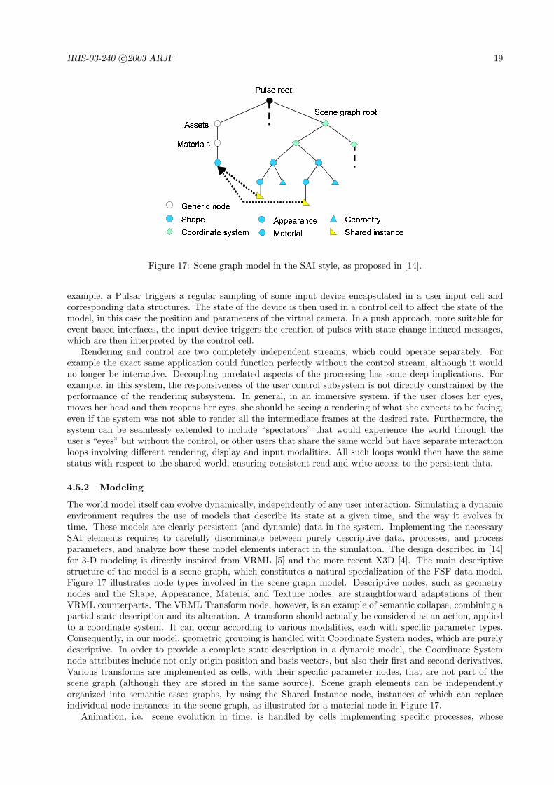
Figure 17: Scene graph model in the SAI style, as proposed in [14].
example, a Pulsar triggers a regular sampling of some input device encapsulated in a user input cell andcorresponding data structures. The state of the device is then used in a control cell to affect the state of themodel, in this case the position and parameters of the virtual camera. In a push approach, more suitable forevent based interfaces, the input device triggers the creation of pulses with state change induced messages,which are then interpreted by the control cell.
Rendering and control are two completely independent streams, which could operate separately. Forexample the exact same application could function perfectly without the control stream, although it wouldno longer be interactive. Decoupling unrelated aspects of the processing has some deep implications. Forexample, in this system, the responsiveness of the user control subsystem is not directly constrained by theperformance of the rendering subsystem. In general, in an immersive system, if the user closes her eyes,moves her head and then reopens her eyes, she should be seeing a rendering of what she expects to be facing,even if the system was not able to render all the intermediate frames at the desired rate. Furthermore, thesystem can be seamlessly extended to include “spectators” that would experience the world through theuser’s “eyes” but without the control, or other users that share the same world but have separate interactionloops involving different rendering, display and input modalities. All such loops would then have the samestatus with respect to the shared world, ensuring consistent read and write access to the persistent data.
4.5.2 Modeling
The world model itself can evolve dynamically, independently of any user interaction. Simulating a dynamicenvironment requires the use of models that describe its state at a given time, and the way it evolves intime. These models are clearly persistent (and dynamic) data in the system. Implementing the necessarySAI elements requires to carefully discriminate between purely descriptive data, processes, and processparameters, and analyze how these model elements interact in the simulation. The design described in [14]for 3-D modeling is directly inspired from VRML [5] and the more recent X3D [4]. The main descriptivestructure of the model is a scene graph, which constitutes a natural specialization of the FSF data model.Figure 17 illustrates node types involved in the scene graph model. Descriptive nodes, such as geometrynodes and the Shape, Appearance, Material and Texture nodes, are straightforward adaptations of theirVRML counterparts. The VRML Transform node, however, is an example of semantic collapse, combining apartial state description and its alteration. A transform should actually be considered as an action, appliedto a coordinate system. It can occur according to various modalities, each with specific parameter types.Consequently, in our model, geometric grouping is handled with Coordinate System nodes, which are purelydescriptive. In order to provide a complete state description in a dynamic model, the Coordinate Systemnode attributes include not only origin position and basis vectors, but also their first and second derivatives.Various transforms are implemented as cells, with their specific parameter nodes, that are not part of thescene graph (although they are stored in the same source). Scene graph elements can be independentlyorganized into semantic asset graphs, by using the Shared Instance node, instances of which can replaceindividual node instances in the scene graph, as illustrated for a material node in Figure 17.
Animation, i.e. scene evolution in time, is handled by cells implementing specific processes, whose
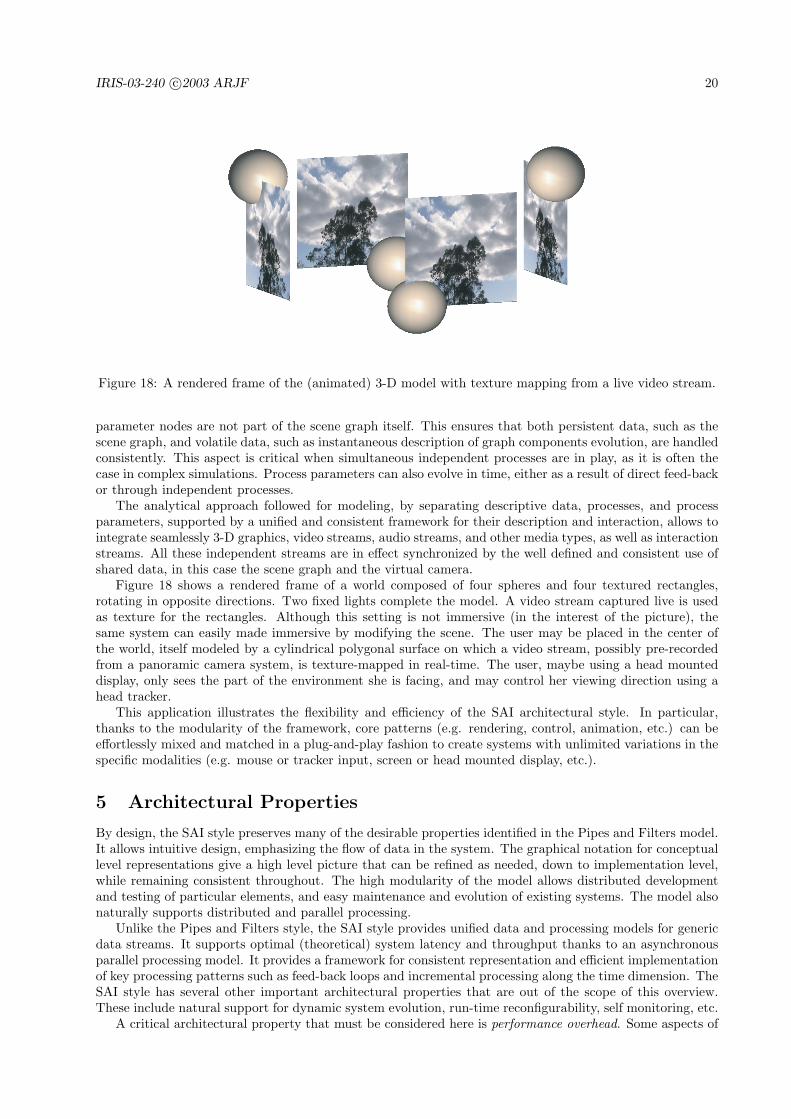
Figure 18: A rendered frame of the (animated) 3-D model with texture mapping from a live video stream.
parameter nodes are not part of the scene graph itself. This ensures that both persistent data, such as thescene graph, and volatile data, such as instantaneous description of graph components evolution, are handledconsistently. This aspect is critical when simultaneous independent processes are in play, as it is often thecase in complex simulations. Process parameters can also evolve in time, either as a result of direct feed-backor through independent processes.
The analytical approach followed for modeling, by separating descriptive data, processes, and processparameters, supported by a unified and consistent framework for their description and interaction, allows tointegrate seamlessly 3-D graphics, video streams, audio streams, and other media types, as well as interactionstreams. All these independent streams are in effect synchronized by the well defined and consistent use ofshared data, in this case the scene graph and the virtual camera.
Figure 18 shows a rendered frame of a world composed of four spheres and four textured rectangles,rotating in opposite directions. Two fixed lights complete the model. A video stream captured live is usedas texture for the rectangles. Although this setting is not immersive (in the interest of the picture), thesame system can easily made immersive by modifying the scene. The user may be placed in the center ofthe world, itself modeled by a cylindrical polygonal surface on which a video stream, possibly pre-recordedfrom a panoramic camera system, is texture-mapped in real-time. The user, maybe using a head mounteddisplay, only sees the part of the environment she is facing, and may control her viewing direction using ahead tracker.
This application illustrates the flexibility and efficiency of the SAI architectural style. In particular,thanks to the modularity of the framework, core patterns (e.g. rendering, control, animation, etc.) can beeffortlessly mixed and matched in a plug-and-play fashion to create systems with unlimited variations in thespecific modalities (e.g. mouse or tracker input, screen or head mounted display, etc.).
5 Architectural Properties
By design, the SAI style preserves many of the desirable properties identified in the Pipes and Filters model.It allows intuitive design, emphasizing the flow of data in the system. The graphical notation for conceptuallevel representations give a high level picture that can be refined as needed, down to implementation level,while remaining consistent throughout. The high modularity of the model allows distributed developmentand testing of particular elements, and easy maintenance and evolution of existing systems. The model alsonaturally supports distributed and parallel processing.
Unlike the Pipes and Filters style, the SAI style provides unified data and processing models for genericdata streams. It supports optimal (theoretical) system latency and throughput thanks to an asynchronousparallel processing model. It provides a framework for consistent representation and efficient implementationof key processing patterns such as feed-back loops and incremental processing along the time dimension. TheSAI style has several other important architectural properties that are out of the scope of this overview.These include natural support for dynamic system evolution, run-time reconfigurability, self monitoring, etc.
A critical architectural property that must be considered here is performance overhead. Some aspects of
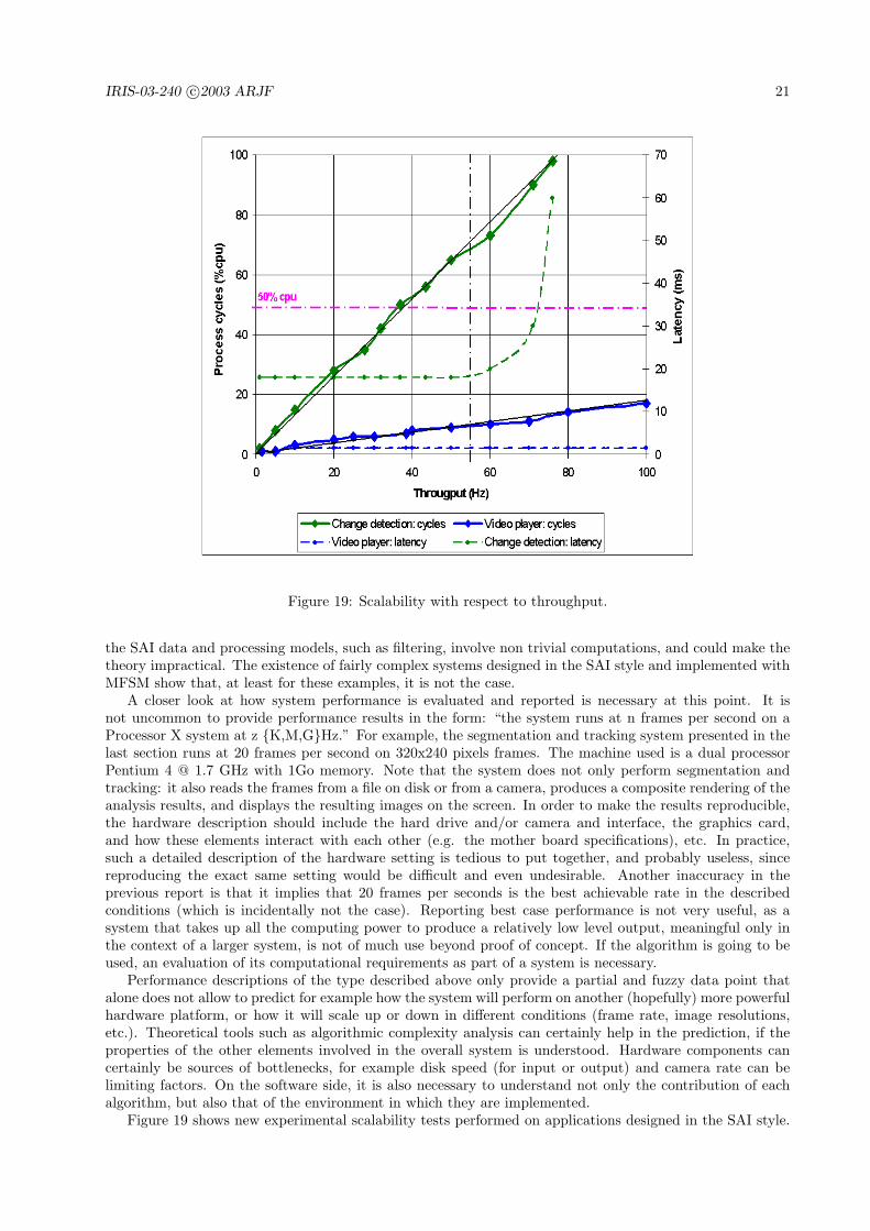
Figure 19: Scalability with respect to throughput.
the SAI data and processing models, such as filtering, involve non trivial computations, and could make thetheory impractical. The existence of fairly complex systems designed in the SAI style and implemented withMFSM show that, at least for these examples, it is not the case.
A closer look at how system performance is evaluated and reported is necessary at this point. It isnot uncommon to provide performance results in the form: “the system runs at n frames per second on aProcessor X system at z {K,M,G}Hz.” For example, the segmentation and tracking system presented in thelast section runs at 20 frames per second on 320x240 pixels frames. The machine used is a dual processorPentium 4 @ 1.7 GHz with 1Go memory. Note that the system does not only perform segmentation andtracking: it also reads the frames from a file on disk or from a camera, produces a composite rendering of theanalysis results, and displays the resulting images on the screen. In order to make the results reproducible,the hardware description should include the hard drive and/or camera and interface, the graphics card,and how these elements interact with each other (e.g. the mother board specifications), etc. In practice,such a detailed description of the hardware setting is tedious to put together, and probably useless, sincereproducing the exact same setting would be difficult and even undesirable. Another inaccuracy in theprevious report is that it implies that 20 frames per seconds is the best achievable rate in the describedconditions (which is incidentally not the case). Reporting best case performance is not very useful, as asystem that takes up all the computing power to produce a relatively low level output, meaningful only inthe context of a larger system, is not of much use beyond proof of concept. If the algorithm is going to beused, an evaluation of its computational requirements as part of a system is necessary.
Performance descriptions of the type described above only provide a partial and fuzzy data point thatalone does not allow to predict for example how the system will perform on another (hopefully) more powerfulhardware platform, or how it will scale up or down in different conditions (frame rate, image resolutions,etc.). Theoretical tools such as algorithmic complexity analysis can certainly help in the prediction, if theproperties of the other elements involved in the overall system is understood. Hardware components cancertainly be sources of bottlenecks, for example disk speed (for input or output) and camera rate can belimiting factors. On the software side, it is also necessary to understand not only the contribution of eachalgorithm, but also that of the environment in which they are implemented.
Figure 19 shows new experimental scalability tests performed on applications designed in the SAI style.
The results are in accordance with those reported in [18]. The figure plots processing load, in percent,against processing rate, in frames per seconds, for an application performing video capture, segmentation bychange detection, and result visualization, and the same plot for the same application with the segmentationturned off (the image displayed is the input). Both applications scale linearly with respect to throughput.All conditions being equal, the difference in slope between the two curves characterizes the processing loadimposed by the segmentation part. Note that these tests were performed on a dual processor machine, so thatthe processor load is an average of the load of both processors. Because of the parallelism (multithreadingin this case), the overall load is balanced between the two processors (by the operating system in this case).As a result, the system is completely oblivious to the 50% cpu load barrier. The figure also plots systemlatency, in ms, against processing rate, for both applications. The latency remains constant as long assystem resources are available. In a sequential system, the latency would be directly proportional to thethroughput, and in fact dictate the maximum achievable throughput. When a bottleneck is encountered(or some resources are exhausted), latency increases and system performance degrades. The segmentationapplication performance (in terms of latency) starts degrading around 55 frames per seconds, although thesystem can still achieve rates above 70 frames per second in these conditions.
These plots suggest that: (1) as long as computing resources are available, the overhead introduced bythe SAI processing model remains constant, and (2) the contribution of the different processes are combinedlinearly. In particular, the model does not introduce any non-linear complexity in the system. Theseproperties are corroborated by empirical results and experience in developing and operating other systemsdesigned in the SAI style. Theoretical complexity analysis and overhead bounding are out of the scope ofthis document.
6 MFSM: An Architectural Middleware
MFSM (Modular Flow Scheduling Middleware) [12] is an architectural middleware implementing the coreelements of the SAI style. MFSM is an open source project, released under the GNU Lesser General PublicLicense [1]. The goal of MFSM is to support and promote the design, analysis and implementation ofapplications in the SAI style. This goal is reflected in the different facets of the project.
• The FSF library is an extensible set of implementation-level classes representing the key elements ofSAI. They can be specialized to define new data structures and processes, or encapsulate existing ones(e.g. from operating system services and third-party libraries).
• A number of software modules regroup specializations implementing specific algorithms or functional-ities. They constitute a constantly growing base of open source, reusable code, maintained as part ofthe MFSM project. Related functional modules may be grouped into libraries.
• An evolving set of example applications illustrates the use of FSF and specific modules.
• An evolving set of documents provides reference and example material. These include a user guide, areference guide and various tutorials.
Figure 20 shows the overall system architecture suggested by MFSM. The middleware layer providesan abstraction level between low-level services and applications, in the form of SAI software elements. Atthe core of this layer is the Flow Scheduling Framework (FSF) [13, 17], an extensible set of foundationclasses that implement SAI style elements. The generic extensible data model allows to encapsulate existingdata formats and standards as well as low-level service protocols and APIs, and make them available in asystem where they can interoperate. The hybrid shared repository and message passing communication andparallel processing model supports control, asynchronous concurrent processing and synchronization of datastreams. The application layer can host a data-stream processing software system, specified and implementedas instances of SAI components and their relationships.
In its current implementation, the FSF library contains a set of C++ classes implementing SAI elements:the source, the nodes and pulses, the cells, the filters, the handles. It also contains classes for two implemen-tation related object types: the factories and the System. An online reference guide [12] provides detailedinterface description and implementation notes for all the classes defined in the FSF library.
Figure 20: Overall system architecture suggested by MFSM.
7 Conclusion
7.1 Summary
This report introduced SAI, a software architecture model for designing, analyzing and implementing appli-cations performing distributed, asynchronous parallel processing of generic data streams. The goal of SAIis to provide a universal framework for the distributed implementation of algorithms and their easy integra-tion into complex systems that exhibit desirable software engineering qualities such as efficiency, scalability,extensibility, reusability and interoperability.
SAI specifies a new architectural style (components, connectors and constraints). The underlying ex-tensible data model and hybrid (shared repository and message-passing) distributed asynchronous parallelprocessing model allow natural and efficient manipulation of generic data streams, using existing libraries ornative code alike. The modularity of the style facilitates distributed code development, testing, and reuse,as well as fast system design and integration, maintenance and evolution. A graph-based notation for ar-chitectural designs allows intuitive system representation at the conceptual and logical levels, while at thesame time mapping closely to processes.
Architectural patterns were illustrated through a number of Computer Vision-related demonstrationprojects ranging from single stream automatic real-time video processing to fully integrated distributedinteractive systems mixing live video, graphics, sound, etc. By design, the SAI style preserves desirableproperties identified in the classic Pipes and Filters model. These include modularity and natural supportfor parallelism. Unlike the Pipes and Filters model, the SAI style allows to achieve optimal (theoretical)system latency and throughput, and provides a unified framework for consistent representation and efficientimplementation of fundamental processing patterns such as feed-back loops and incremental processing alongthe time dimension.
SAI is supported by MFSM, an open source architectural middleware. The MFSM project is composedof a solid foundation library and a constantly growing base of open source, reusable code. The project isthoroughly documented, and comprises a user guide, reference guide and tutorials.
7.2 Perspectives
The SAI architectural style exhibit properties that make it relevant to research, educational and even indus-trial projects.
Thanks to its modularity, it can accommodate today’s requirements while preparing for tomorrow’sapplications. Using the SAI style for research can not only save time by avoiding to re-develop existingmodules, it can also reduce the technology transfer time once the research has matured.
SAI also allows distributed development of functional modules, and their seamless integration into com-plex systems. The modularity of the design also allows gradual development, facilitating continuing validationand naturally supporting regular delivery of incremental system prototypes. A number of cross-disciplinaryresearch projects, in addition to those described above in section 4, are already leveraging these properties.They are producing real-time, interactive systems spanning a range of research domains.
Using the SAI style for research can also reduce the technology transfer time once the research hasmatured. From an industry point of view, the SAI style allows fast prototyping for proof-of-concept demon-strations.
For education, SAI allows to efficiently relate classroom projects to the realities of the research laboratory,and of industrial software development. A project-oriented Integrated Media Systems class based on SAI,and applying the distributed development model, was taught at USC in the Fall 2002 semester at the advancegraduate level. Rather than having small teams of students develop a same, simple complete project, thesmall teams first implemented complementary parts of an overall, much more complex project (distributedsoccer game). After six weeks of distributed development, sanctioned by careful incremental cross-testing,all the pieces were put together to produce a playable system. The course was an outstanding success, andregular graduate and undergraduate courses based on this model are in the planning.
Beyond the ones highlighted in the context of this chapter, the SAI style has several important desirablearchitectural properties that make it a promising framework for many applications in various fields. Theseproperties include natural support for dynamic system evolution, run-time reconfigurability, self monitoring,etc. Application of SAI in various contexts is currently being explored (e.g. interactive immersive systems).Short term technical developments for SAI include development of a Graphical User Interface for systemarchitecture design. Architecture validation and monitoring and analysis tools will be gradually integrated.
Finally, from a theoretical point of view, because of the explicit distinction between volatile and persistentdata, SAI is a unified computational model that bridges the conceptual and practical gap between signal(data stream) processing on the one hand, and the computation of higher level data (persistent, dynamicstructures) on the other hand. As such, it might prove to be not only a powerful tool for implementing, butalso for modeling and reasoning about problems spanning both aspects. An example is Computer Vision.
Acknowledgments
The following (then) graduate students were involved in some of the projects presented in section 4: Dr.Elaine Kang (Video Painting, Virtual Mirror), Maurya Shah (IMSC Communicator–networking and com-pression), Kevin Zhu (IMSC Communicator–video and sound capture and synchronized rendering).
This work has been funded in part by the Integrated Media Systems Center, a National Science Founda-tion Engineering Research Center, Cooperative Agreement No. EEC-9529152. Any Opinions, findings andconclusions or recommendations expressed in this material are those of the author(s) and do not necessarilyreflect those of the National Science Foundation.
This work was supported in part by the Advanced Research and Development Activity of the U.S.Government under contract No. MDA-908-00-C-0036.
References
[1] Gnu Lesser General Public License. URL http://www.gnu.org/copyleft/lesser.html.
[2] Intel Open Source Computer Vision Library. URL http://www.intel.com/research/mrl/research/opencv/.
[6] PETS01: Second IEEE International Workshop on Performance Evaluations of Tracking and Surveil-lance, December 2001. URL http://pets2001.visualsurveillance.org.
[7] PETS02: Third IEEE International Workshop on Performance Evaluations of Tracking and Surveillance,June 2002. URL http://pets2002.visualsurveillance.org.
[8] PETS-ICVS: Fourth IEEE International Workshop on Performance Evaluations of Tracking and Surveil-lance, March 2003. URL http://petsicvs.visualsurveillance.org.
[9] PETS-VS: Joint IEEE International Workshop on Visual Surveillance and Performance Evaluations ofTracking and Surveillance, October 2003. URL http://vspets.visualsurveillance.org.
[10] G. R. Andrews. Foundations of multithreaded, parallel and distributed programming. Addison Wesley,2000.
[11] K. W. Arthur, K. S. Booth, and C. Ware. Evaluating 3d task performance for fish tank virtual worlds.ACM Transactions on Information Systems, 11(3):239–265, 1993.
[12] A. R.J. Francois. Modular Flow Scheduling Middleware. URL http://mfsm.sourceForge.net.
[13] A. R.J. Francois. Semantic, Interactive Manipulation of Visual Data. PhD thesis, Dept. of ComputerScience, University of Southern California, Los Angeles, CA, 2000.
[14] A. R.J. Francois. Components for immersion. In Proceedings of the IEEE International Conference onMultimedia and Expo. Lausanne, Switzerland, August 2002.
[15] A. R.J. Francois and E. Kang. A handheld mirror simulation. In Proceedings of the IEEE InternationalConference on Multimedia and Expo. Baltimore, MD, July 2003.
[16] A. R.J. Francois, E. Kang, and U. Malesci. A handheld virtual mirror. In ACM SIGGRAPH ConferenceAbstracts and Applications proceedings, page 140. San Antonio, TX, July 2002.
[17] A. R.J. Francois and G. G. Medioni. A modular middleware flow scheduling framework. In Proceedingsof ACM Multimedia 2000, pages 371–374. Los Angeles, CA, November 2000.
[18] A. R.J. Francois and G. G. Medioni. A modular software architecture for real-time video processing.In Springer-Verlag, editor, IEEE International Workshop on Computer Vision Systems, pages 35–49.Vancouver, B.C., Canada, July 2001.
[19] C. Jaynes, S. Webb, R. M. Steele, and Xiong Q. An open development environment for evaluation ofvideo surveillance systems. In PETS02, pages 32–39. Copenhagen, Denmark, June 2002.
[20] M. B. Jones and J. Regehr. The problems you’re having may not be the problems you think you’rehaving: results from a latency study of Windows NT. In Proceeedings of the Seventh Workshop on HotTopics in Operating Systems. Rio Rico, AZ, 1999.
[21] E.Y. Kang, I. Cohen, and G.G. Medioni. A graph-based global registration for 2d mosaics. In ICPR00,pages Vol I: 257–260, 2000.
[22] M. Lazzari, A. Francois, M. L. McLaughlin, J. Jaskowiak, W. L. Wong, Akbarian M., Peng W., andZhu W. Using haptics and a ”virtual mirror” to exhibit museum objects with reflective surfaces. InProceedings of the 11th International Conference on Advanced Robotics. Coimbra, Portugal, July 2003.
[23] I. S. McKenzie and C. Ware. Lag as a determinant of human performance in interactive systems. InProceedings of the ACM Conference on Human Factors in Computing Systems - INTERCHI, pages488–493, 1993.
[27] D. Terzopoulos and C. M. Brown, editors. Real-Time Computer Vision. Cambridge University Press,1995.
[28] K. Toyama, J. Krumm, B. Brumitt, and B. Meyers. Wallflower: Principles and practice of backgroundmaintenance. In Proceedingsz of the International Conference on Computer Vision, pages 255–261,1999.