Americas Headquarters Cisco Systems, Inc. 170 West Tasman Drive San Jose, CA 95134-1706 USA http://www.cisco.com Tel: 408 526-4000 800 553-NETS (6387) Fax: 408 527-0883 Software Configuration Guide for Cisco IOS Release 15.1(2)GC Text Part Number: OL-23478-01
Cisco IOS Release 15.1(2)GCTHE SPECIFICATIONS AND INFORMATION REGARDING THE PRODUCTS IN THIS MANUAL ARE SUBJECT TO CHANGE WITHOUT NOTICE. ALL STATEMENTS, INFORMATION, AND RECOMMENDATIONS IN THIS MANUAL ARE BELIEVED TO BE ACCURATE BUT ARE PRESENTED WITHOUT WARRANTY OF ANY KIND, EXPRESS OR IMPLIED. USERS MUST TAKE FULL RESPONSIBILITY FOR THEIR APPLICATION OF ANY PRODUCTS.
THE SOFTWARE LICENSE AND LIMITED WARRANTY FOR THE ACCOMPANYING PRODUCT ARE SET FORTH IN THE INFORMATION PACKET THAT SHIPPED WITH THE PRODUCT AND ARE INCORPORATED HEREIN BY THIS REFERENCE. IF YOU ARE UNABLE TO LOCATE THE SOFTWARE LICENSE OR LIMITED WARRANTY, CONTACT YOUR CISCO REPRESENTATIVE FOR A COPY.
NOTWITHSTANDING ANY OTHER WARRANTY HEREIN, ALL DOCUMENT FILES AND SOFTWARE OF THESE SUPPLIERS ARE PROVIDED “AS IS” WITH ALL FAULTS. CISCO AND THE ABOVE-NAMED SUPPLIERS DISCLAIM ALL WARRANTIES, EXPRESSED OR IMPLIED, INCLUDING, WITHOUT LIMITATION, THOSE OF MERCHANTABILITY, FITNESS FOR A PARTICULAR PURPOSE AND NONINFRINGEMENT OR ARISING FROM A COURSE OF DEALING, USAGE, OR TRADE PRACTICE.
IN NO EVENT SHALL CISCO OR ITS SUPPLIERS BE LIABLE FOR ANY INDIRECT, SPECIAL, CONSEQUENTIAL, OR INCIDENTAL DAMAGES, INCLUDING, WITHOUT LIMITATION, LOST PROFITS OR LOSS OR DAMAGE TO DATA ARISING OUT OF THE USE OR INABILITY TO USE THIS MANUAL, EVEN IF CISCO OR ITS SUPPLIERS HAVE BEEN ADVISED OF THE POSSIBILITY OF SUCH DAMAGES.
Cisco and the Cisco Logo are trademarks of Cisco Systems, Inc. and/or its affiliates in the U.S. and other countries. A listing of Cisco's trademarks can be found at www.cisco.com/go/trademarks. Third party trademarks mentioned are the property of their respective owners. The use of the word partner does not imply a partnership relationship between Cisco and any other company. (1005R)
Any Internet Protocol (IP) addresses and phone numbers used in this document are not intended to be actual addresses and phone numbers. Any examples, command display output, network topology diagrams, and other figures included in the document are shown for illustrative purposes only. Any use of actual IP addresses or phone numbers in illustrative content is unintentional and coincidental.
Software Configuration Guide for Cisco IOS Release 15.1(2)GC
Finding Support Information for Platforms and Cisco IOS and Catalyst OS Software Images 1-2
C H A P T E R 2 Command Line Interfaces 2-1
Accessing the CLI 2-1
Performing Command Line Processing 2-1
Performing History Substitution 2-2
Understanding Cisco IOS Command Modes 2-2
Working with Frequently Used Command Modes 2-3
Using the “do” Command 2-4
Getting a List of Commands and Syntax 2-5
C H A P T E R 3 Configuring Interfaces and Verifying Connectivity 3-1
Using the Interface Command 3-1
Configuring fastEthernet Interface Features 3-3
Configuring an IP Address 3-3
Adding a Description for an Interface 3-3
Monitoring and Maintaining Interfaces 3-4
Monitoring Interface and Controller Status 3-4
Clearing and Resetting the Interface Counters 3-6
C H A P T E R 4 Understanding Mobile Ad-hoc Networks for Router-to-Radio Communications 4-1
Understanding MANETs 4-1
Identifying Prerequisites for MANETs for Router-to-Radio Communications 4-2
Understanding MANET Restrictions for Router-to-Radio Communications 4-2
Defining Benefits of Router-to-Radio Links Using VMIsin Cisco IOS Software 4-2
Routing Challenges for MANETs 4-2
Understanding PPPoE Interfaces for Mobile Radio Communications 4-3
Understanding VMI 4-4
Understanding Link Quality Metrics Reporting for OSPFv3 and EIGRP with VMI Interfaces 4-5
Understanding Neighbor Up/Down Signaling for OSFPv3 and EIGRP 4-6
iiiSoftware Configuration Guide for Cisco IOS, Release 15.1(2) GC
Contents
Understanding PPPoE Credit-based Flow Control 4-7
C H A P T E R 5 Configuring Virtual Multipoint Interfaces 5-1
Understanding Virtual Multipoint Interfaces 5-1
Configuring PPPoE to Use with VMI 5-2
Creating a Subscriber Profile for PPPoE Service Selection 5-2
Configuring the PPPoE Profile for PPPoE Service Selection 5-3
Configuring PPPoE on an Ethernet Interface 5-4
Configuring a Virtual Template Interface for use with VMI 5-5
Configuring VMI 5-7
Understanding Multicast Support for VMI 5-9
Using Bypass Mode 5-10
Enabling Multicast Support on a VMI 5-10
Showing VMI Neighbors 5-12
Defining Multicast Routing in NBMA Mode 5-20
Understanding QoS Configuration for VMI 5-21
C H A P T E R 6 OSPFv3 Address Families 6-1
Configuring OSPFv3 Address Families 6-1
Enabling IPv6 6-2
Enabling IPv6 on the Interface 6-3
Configuring OSPFv3 for a Unicast Address Family 6-3
Configuring OSPFv3 for an IPv6 Unicast Address Family 6-4
Configuring OSPFv3 for an IPv4 Unicast Address Family 6-7
Working with Multiple Address Families 6-11
Redistributing IPv4 Routes 6-12
Verifying OSPFv3 Address Families Configuration and Operation 6-14
C H A P T E R 7 Configuring OSPFv3 for MANETs 7-1
Understanding How OSPFv3 Works with MANETs 7-1
Enabling IPv6 Routing 7-2
Enabling IPv6 on the Interface 7-3
Configuring the OSPFv3 Process 7-4
Configuring OSPFv3 in MANETs on the Interface 7-5
Configuring OSPFv3 in MANETs for Radio Aware Routing 7-7
Fine Tuning Radio Aware Routing Metrics for OSPFv3 MANET 7-8
Understanding OSPFv3 MANET Selective Peering 7-11
Enabling Selective Peering 7-11
ivSoftware Configuration Guide for Cisco IOS, Release 15.1(2) GC
OL-23478-01
Contents
Preventing FULL Peering with Neighbors over Poor Links 7-13
Fine Tuning Selective Peering with Link Metrics 7-14
Verifying OSPFv3 MANET Configuration and Operation 7-16
C H A P T E R 8 Configuring the Enhanced Interior Gateway Routing Protocol in a MANET 8-1
Understanding The Enhanced Interior Gateway Protocol 8-1
Using EIGRP Cost Metrics for VMI Interfaces 8-2
Understanding VMI Metric to EIGRP Metric Conversion 8-4
Understanding EIGRP Metric Dampening for VMI 8-5
Understanding Neighbor Up/Down Signaling for EIGRP 8-6
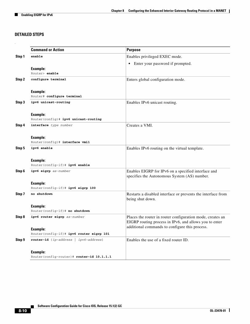
Enabling EIGRP for IPv4 8-7
Activating EIGRP IPv4 on a Configured VMI 8-8
Enabling EIGRP for IPv6 8-9
Setting the EIGRP Metric Change-based Dampening for VMI 8-11
Setting the EIGRP Interval-based Metric Dampening for VMI 8-12
C H A P T E R 9 Configuring Router-Radio Control Protocol 9-1
Configuring R2CP on the Router 9-2
Configuring the Heartbeat Threshold 9-2
Configuring the Node Terminate ACK Threshold 9-3
Configuring the Node Terminate ACK Timeout 9-4
Configuring the Port Number for the Server 9-5
Configuring the Session Activity Timeout 9-6
Configuring the Session Terminate ACK Threshold 9-7
Configuring the Session Terminate ACK Timeout 9-8
Configuring the Virtual Access Template Number 9-9
Verifying R2CP Configuration 9-10
Displaying Radio Clients on an R2CP Interface 9-11
Displaying R2CP Router Configuration 9-12
Displaying Neighbors on an R2CP Interface 9-12
Defining QoS Shaping in Virtual Templates 9-13
Configuring QoS for Virtual Templates 9-13
Configuring Classes 9-13
Configuring Policies 9-14
Assigning Policies to the Virtual Interface 9-14
A P P E N D I X A Command Reference A-1
clear ospfv3 A-3
vSoftware Configuration Guide for Cisco IOS, Release 15.1(2) GC
OL-23478-01
Contents
clear pppoe relay context A-5
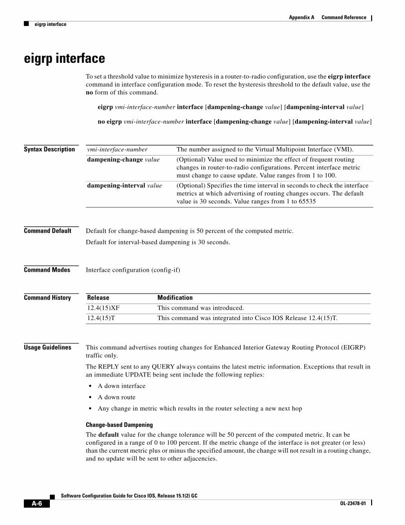
eigrp interface A-6
interface vmi A-8
ip r2cp heartbeat-threshold A-10
ip r2cp node-terminate-ack-threshold A-11
ip r2cp node-terminate-ack-timeout A-12
ip r2cp port A-13
ip r2cp session-activity-timeout A-14
ip r2cp session-terminate-ack-threshold A-15
ip r2cp session-terminate-ack-timeout A-16
ip r2cp virtual-template A-17
ipv6 redirects A-18
keepalive A-20
manet cache A-22
manet hello unicast A-24
manet peering selective A-25
manet willingness A-26
mode A-28
ospfv3 area A-30
ospfv3 cost dynamic A-31
ospfv3 cost dynamic default A-33
ospfv3 cost dynamic hysteresis A-34
ospfv3 cost dynamic weight A-36
ospfv3 dead-interval A-38
ospfv3 hello-interval A-39
ospfv3 manet peering cost A-40
ospfv3 manet peering link-metrics A-42
ospfv3 network A-43
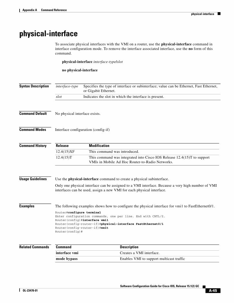
physical-interface A-45
router ospfv3 A-46
show ip eigrp neighbors A-47
show ip redirects A-48
show ipv6 eigrp neighbors A-49
show ospfv3 A-50
show ospfv3 database A-52
viSoftware Configuration Guide for Cisco IOS, Release 15.1(2) GC
OL-23478-01
Contents
show ospfv3 flood-list A-55
show ospfv3 interface A-57
show ospfv3 neighbor A-59
show ospfv3 neighbor manet A-63
show ospfv3 promiscuous acknowledgments A-64
show pppoe A-65
show pppoe derived A-67
show pppoe session A-68
show r2cp clients A-70
show r2cp config A-72
show r2cp neighbors A-74
show vmi neighbors A-75
summary-prefix (OSPFv3) A-79
timers manet A-81
timers throttle spf A-83
A P P E N D I X B Acronyms and Abbreviations B-1
viiSoftware Configuration Guide for Cisco IOS, Release 15.1(2) GC
OL-23478-01
Contents
viiiSoftware Configuration Guide for Cisco IOS, Release 15.1(2) GC
OL-23478-01
CISCO Conf iden t i a l EFT Dra ft
Preface
This preface describes the audience, organization, and conventions of the Software Configuration Guide, Cisco IOS Release 15.1(2)GC and provides information on how to obtain related documents and technical assistance.
This preface includes the following topics:
• Audience, page ix
• Organization, page x
• Related Documentation, page x
• Conventions, page xi
• Obtaining Documentation, Support, and Security Guidelines, page xii
AudienceThis guide is for experienced network administrators who will use the software on products they have to test their mobile networks.
ixSoftware Configuration Guide for Cisco IOS, Release 15.1(2) GC
OL-23478-01
Preface
OrganizationThis guide is organized into the following chapters:
Related DocumentationCisco IOS configuration guides and command references for Software Release 15.1(2)GC. Use these publications to help you configure Cisco IOS software features not described in the preceding publications.
The most current Cisco IOS configuration guides and command references are located at the following URL:http://www.cisco.com/en/US/products/ps10592/prod_release_notes_list.html
Additional documentation for Software Release 15.1(2)GC includes the following documents:
ConventionsThis document uses the following typographical conventions:
Notes use the following conventions:
Note Means reader take note. Notes contain helpful suggestions or references to material not covered in the publication.
Cautions use the following conventions:
Caution Means reader be careful. In this situation, you might do something that could result in equipment damage or loss of data.
Warnings use the following conventions:
Warning Safety warnings appear throughout this publication in procedures that, if performed incorrectly, may cause harm to you or the equipment. A warning symbol precedes each warning statement.
Convention Description
boldface font Commands, command options, and keywords are in boldface.
italic font Command arguments for which you supply values are in italics.
[ ] Command elements in square brackets are optional.
{ x | y | z } Alternative keywords in command lines are grouped in braces and separated by vertical bars.
[ x | y | z ] Optional alternative keywords are grouped in brackets and separated by vertical bars.
string A nonquoted set of characters. Do not use quotation marks around the string because the string will include the quotation marks.
screen font System displays are in screen font.
boldface screen font
Information you must enter verbatim is in boldface screen font.
italic screen font Arguments for which you supply values are in italic screen font.
This pointer highlights an important line of text in an example.
^ Represents the key labeled Control—for example, the key combination ^D in a screen display means hold down the Control key while you press the D key.
< > Nonprinting characters such as passwords are in angle brackets.
xiSoftware Configuration Guide for Cisco IOS, Release 15.1(2) GC
OL-23478-01
Preface
Commands in Task TablesCommands listed in task tables show only the relevant information for completing the task and not all available options for the command. For a complete description of a command, refer to Appendix A, Command Reference.
Obtaining Documentation, Support, and Security GuidelinesFor information on obtaining documentation, obtaining support, providing documentation feedback, security guidelines, and also recommended aliases and general Cisco documents, see the monthly What’s New in Cisco Product Documentation, which also lists all new and revised Cisco technical documentation, at the following URL:
This chapter includes the following major sections:
• Features, page 1-1
• Finding Feature Information in this Module, page 1-2
• Finding Support Information for Platforms and Cisco IOS and Catalyst OS Software Images, page 1-2
FeaturesThis section describes the key features for the Cisco IOS Release 15.1(2) GC release:
• Mobile Ad Hoc Networks (MANET)—MANET for router-to-radio communications address the challenges faced when merging IP routing and mobile radio communications in ad hoc networking applications. For more information, see Chapter 4, “Understanding Mobile Ad-hoc Networks for Router-to-Radio Communications.”
• Virtual Multipoint Interfaces (VMI)—VMI provides services that map outgoing packets to the appropriate Point-to-Point Protocol over Ethernet (PPPoE) sessions based on the next-hop forwarding address for that packet. The VMI also provides a broadcast service that emulates a set of point-to-point connections as a point-to-multipoint interface with broadcast ability. For more information, see Chapter 5, “Configuring Virtual Multipoint Interfaces.”
• Enhanced Interior Gateway Routing Protocol (EIGRP)—EIGRP integrates the capabilities of link-state protocols into distance vector protocols. EIGRP is distinguished from other routing protocols by key capabilities, including fast convergence, support for variable-length subnet mask, support for partial updates, and support for multiple network layer protocols. For more information, see Chapter 6, “OSPFv3 Address Families.”
• Router-Radio Control Protocol (R2CP)—R2CP provides a bi-directional, event driven communication channel between the router and the modem. Event driven communication reduces convergence time and decreases the overhead traffic that must be sent to the radio link. R2CP allows real-time link quality metrics on a neighbor-by-neighbor basis. R2CP supports Broadcast Multi-Access (BMA) radios that operate in rapidly changing mobile environments. For more information, see Chapter 9, “Configuring Router-Radio Control Protocol.”
1-1nfiguration Guide for Cisco IOS, Release 15.1(2) GC
Chapter 1 Product OverviewFinding Feature Information in this Module
Finding Feature Information in this ModuleYour Cisco IOS software release may not support all of the features documented in this module. To reach links to specific feature documentation in this module and to see a list of the releases in which each feature is supported, see Appendix A, “Command Reference”.
Finding Support Information for Platforms and Cisco IOS and Catalyst OS Software Images
Use Cisco Feature Navigator to find information about platform support and Cisco IOS and Catalyst OS software image support. To access Cisco Feature Navigator, go to http://www.cisco.com/go/cfn. An account on Cisco.com is not required.
1-2Software Configuration Guide for Cisco IOS, Release 15.1(2) GC
OL-23478-01
Software CoOL-23478-01
C H A P T E R 2
Command Line Interfaces
This chapter describes the Command Line Interface (CLI) you use to configure platforms utilizing Cisco IOS 15.1(2) GC. This chapter includes the following major sections:
• Accessing the CLI, page 2-1
• Performing Command Line Processing, page 2-1
• Performing History Substitution, page 2-2
• Understanding Cisco IOS Command Modes, page 2-2
• Getting a List of Commands and Syntax, page 2-5
Note Any Internet Protocol (IP) addresses used in this document are not intended to be actual addresses. Any examples, command display output, and figures included in the document are shown for illustrative purposes only. Any use of actual IP addresses in illustrative content is unintentional and coincidental.
Note The examples in this chapter are not specific to the Cisco 5940.
Accessing the CLI You can access the Cisco IOS CLI through the Gigabit Ethernet 0/0 interface using Secure Shell (SSh) or Telnet to establish a Virtual TeletYpe (VTY) session with the router.
After accessing the CLI on the router, the screen displays the following message:
Press Return for Console prompt
Router> enablePassword:< >Router#
Performing Command Line ProcessingCommands are not case-sensitive. You can abbreviate commands and parameters if the abbreviations contain enough letters to be different from any other currently available commands or parameters.
You can scroll through the last 20 commands stored in the history buffer and enter or edit a command at the prompt. Table 2-1 lists the keyboard shortcuts for entering and editing commands.
2-1nfiguration Guide for Cisco IOS, Release 15.1(2) GC
Chapter 2 Command Line InterfacesPerforming History Substitution
Performing History SubstitutionThe history buffer stores the last 20 command lines you entered. History substitution enables you to access these command lines without retyping them. Table 2-2 lists the history substitution commands.
Understanding Cisco IOS Command ModesThe Cisco IOS user interface has many different modes: user EXEC, privileged EXEC (enable), global configuration, interface, subinterface, and protocol-specific modes. The commands available to you are dependent on your current command mode. To get a list of the commands in a given mode, enter a question mark (?) at the system prompt. See the Getting a List of Commands and Syntax section for more information.
Note For complete information about Cisco IOS command modes, refer to the Cisco IOS Configuration Fundamentals Configuration Guide and the Cisco IOS Configuration Fundamentals Command Reference at: http://www.cisco.com/univercd/cc/td/doc/product/software/ios122/122cgcr/index.htm
Table 2-1 Keyboard Shortcuts
Keystrokes Result
Press Ctrl-B or press the Left Arrow key1
1. The Arrow keys function only on ANSI-compatible terminals, such as VT100s.
Moves the cursor back one character.
Press Ctrl-F orpress the Right Arrow key1
Moves the cursor forward one character.
Press Ctrl-A Moves the cursor to the beginning of the command line.
Press Ctrl-E Moves the cursor to the end of the command line.
Press Esc-B Moves the cursor back one word.
Press Esc-F Moves the cursor forward one word.
Table 2-2 History Substitution Commands
Command Purpose
Ctrl-P or the Up Arrow key1
1. The Arrow keys function only on ANSI-compatible terminals such as VT100s.
Recalls commands in the history buffer, beginning with the most recent command. Repeat the key sequence to recall older commands successively.
Ctrl-N or the Down Arrow key1 Returns to more recent commands in the history buffer after commands have been recalled with Ctrl-P or the Up Arrow key. Repeat the key sequence to recall more recent commands.
Router# show history Lists the last several commands you entered in EXEC mode.
2-2Software Configuration Guide for Cisco IOS, Release 15.1(2) GC
Chapter 2 Command Line InterfacesUnderstanding Cisco IOS Command Modes
Working with Frequently Used Command ModesWhen you start a session, you begin in user mode, also called user EXEC mode. Only a small subset of commands are available in EXEC mode. To have access to all commands, you must enter privileged EXEC mode, also called enable mode. To access the privileged EXEC mode, you must enter a password. When you are in the privileged EXEC mode, you can enter any EXEC command or access global configuration mode. Most EXEC commands are one-time commands, such as show commands, which display the current configuration status, and clear commands, which reset counters or interfaces. The EXEC commands are not saved when the Cisco router is rebooted.
The configuration modes allow you to make changes to the running configuration. If you save the configuration, these commands are stored when you reboot the router. You must start in global configuration mode. From global configuration mode, you can enter interface configuration mode, subinterface configuration mode, and a variety of protocol-specific modes.
Table 2-3 lists and describes frequently used Cisco IOS modes.
The Cisco IOS command interpreter, called the EXEC, interprets and runs the commands you enter. You can abbreviate commands and keywords by entering just enough characters to make the command unique from other commands. For example, you can abbreviate the show command to sh and the configure terminal command to config t.
When you type exit, the router backs out one level. To exit configuration mode completely and return to privileged EXEC mode, press Ctrl-Z.
When you type end, the router returns to EXEC mode.
Table 2-3 Frequently Used Cisco IOS Command Modes
Mode What You Use It For How to Access Prompt
User EXEC To connect to remote devices, change terminal settings on a temporary basis, perform basic tests, and display system information.
Log in. Router>
Privileged EXEC (enable)
To set operating parameters. The privileged command set includes the commands in user EXEC mode, as well as the configure command. Use the configure command to access the other command modes.
From user EXEC mode, enter the enable command and the enable password (if a password has been configured).
Router#
Global configuration To configure features that affect the system as a whole, such as the system time or router name.
From privileged EXEC mode, enter the configure terminal command.
Router(config)#
Interface configuration To enable or modify the operation of a Gigabit Ethernet, Fast Ethernet, E1/T1, or smart serial interface with interface commands.
From global configuration mode, enter the interface type location command.
Router(config-if)#
2-3Software Configuration Guide for Cisco IOS, Release 15.1(2) GC
OL-23478-01
Chapter 2 Command Line InterfacesUnderstanding Cisco IOS Command Modes
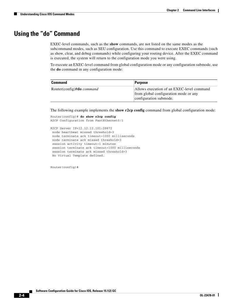
Using the “do” CommandEXEC-level commands, such as the show commands, are not listed on the same modes as the subcommand modes, such as SEU configuration. Use this command to execute EXEC commands (such as show, clear, and debug commands) while configuring your routing device. After the EXEC command is executed, the system will return to the configuration mode you were using.
To execute an EXEC-level command from global configuration mode or any configuration submode, use the do command in any configuration mode:
The following example implements the show r2cp config command from global configuration mode:
Router(config)# do show r2cp configR2CP Configuration from FastEthernet0/1
Router(config)#do command Allows execution of an EXEC-level command from global configuration mode or any configuration submode.
2-4Software Configuration Guide for Cisco IOS, Release 15.1(2) GC
OL-23478-01
Chapter 2 Command Line InterfacesGetting a List of Commands and Syntax
Getting a List of Commands and SyntaxIn any command mode, you can get a list of available commands by entering a question mark (?).
To obtain a list of commands that begin with a particular character sequence, enter those characters followed by the question mark (?). Do not include a space before the question mark. This form of help is called word help, because it completes a word for you.
To list keywords or arguments, enter a question mark in place of a keyword or argument. Include a space before the question mark. This form of help is called command syntax help, because it reminds you which keywords or arguments are applicable based on the command, keywords, and arguments you have already entered.
Router# show cdp ? entry Information for specific neighbor entry interface CDP interface status and configuration neighbors CDP neighbor entries traffic CDP statistics | Output modifiers <cr>
Router#
To redisplay a command you previously entered, press the Up Arrow key or Ctrl-P. You can continue to press the Up Arrow key to see the last 20 commands you entered.
Tip If you are having trouble entering a command, check the system prompt and enter the question mark (?) for a list of available commands. You might be in the wrong command mode or using incorrect syntax.
Type exit to return to the previous mode. Press Ctrl-Z or enter the end command in any mode to immediately return to privileged EXEC mode.
2-5Software Configuration Guide for Cisco IOS, Release 15.1(2) GC
OL-23478-01
Chapter 2 Command Line InterfacesGetting a List of Commands and Syntax
2-6Software Configuration Guide for Cisco IOS, Release 15.1(2) GC
OL-23478-01
Software CoOL-23478-01
C H A P T E R 3
Configuring Interfaces and Verifying Connectivity
This chapter describes how to configure interfaces using Cisco IOS 15.1(2)GC.
This chapter includes the following major sections:
Note For complete syntax and usage information for the router commands used in this chapter, refer to Appendix A, “Command Reference”.
Using the Interface CommandThe following general instructions apply to all interface configuration processes:
Step 1 At the privileged EXEC prompt, enter the configure terminal command to enter global configuration mode:
Router# configure terminalEnter configuration commands, one per line. End with CNTL/Z.Router(config)#
Step 2 In global configuration mode, enter the interface command. Identify the interface type and the number of the connector on the interface card. The following example shows how to select a fastEthernet interface of 0:
Note You do not need to add a space between the interface type and interface number. For example, in the preceding line you can specify either fastEthernet0/0 or fastEthernet 0/0.
3-1nfiguration Guide for Cisco IOS, Release 15.1(2) GC
Chapter 3 Configuring Interfaces and Verifying ConnectivityUsing the Interface Command
Step 3 Interface numbers are assigned at the factory at the time of installation. Enter the show interfaces EXEC command to see a list of all interfaces installed on your router. A report is provided for each interface that your router supports, as shown in this display:
Router(config-if)# Ctrl-ZRouter# show interfacesFastEthernet0/0 is up, line protocol is up Hardware is MV96340 Ethernet, address is 001f.ca0f.6508 (bia 001f.ca0f.6508) Description: OPERATIONS ACCESS - DO NOT CHANGE ADDRESS Internet address is 9.9.9.10/24 MTU 1500 bytes, BW 100000 Kbit/sec, DLY 100 usec, reliability 254/255, txload 1/255, rxload 6/255 Encapsulation ARPA, loopback not set Keepalive set (10 sec) Full-duplex, 100Mb/s, 100BaseTX/FX ARP type: ARPA, ARP Timeout 04:00:00 Last input 00:00:00, output 00:00:06, output hang never Last clearing of "show interface" counters never Input queue: 18/75/0/0 (size/max/drops/flushes); Total output drops: 0 Queueing strategy: fifo Output queue: 0/40 (size/max) 5 minute input rate 2627000 bits/sec, 231 packets/sec 5 minute output rate 0 bits/sec, 0 packets/sec 86251 packets input, 119155372 bytes Received 5158 broadcasts (0 IP multicasts) 0 runts, 0 giants, 1 throttles 27 input errors, 0 CRC, 0 frame, 0 overrun, 27 ignored 0 watchdog 0 input packets with dribble condition detected 35714 packets output, 3513886 bytes, 0 underruns 0 output errors, 0 collisions, 0 interface resets 0 unknown protocol drops 0 babbles, 0 late collision, 0 deferred 0 lost carrier, 0 no carrier 0 output buffer failures, 0 output buffers swapped outRouter#
Step 4 Follow each interface command with the interface configuration commands your particular interface requires. The commands you enter define the protocols and applications that run on the interface. The commands are collected and applied to the interface command until you enter another interface command or press Ctrl-Z to exit interface configuration mode and return to privileged EXEC mode.
Step 5 You can use the exit command to exit interface configuration mode and return to global configuration mode.
Step 6 After you configure an interface, you can check the status of the interface by using the EXEC show commands listed in the “Monitoring and Maintaining Interfaces” section on page 3-4.
3-2Software Configuration Guide for Cisco IOS, Release 15.1(2) GC
OL-23478-01
Chapter 3 Configuring Interfaces and Verifying ConnectivityConfiguring fastEthernet Interface Features
Configuring an IP AddressTo configure an IPv4 address and subnet mask on an interface, perform the following task:
Example
The following example shows how to set the IPv4 address 10.108.1.27 with subnet mask 255.255.255.0 on interface fastEthernet 0/0:
Router(config)# interface fastEthernet 0/0Router(config-if)# ip address 10.108.1.27 255.255.255.0
Adding a Description for an InterfaceYou can add a description about an interface to help you remember its function. The description displays in the output of the following commands: show configuration, show running-config, and show interfaces.
To add a description for an interface, enter the following command in interface configuration mode:
Examples
The following example shows how to add the description “Operations” on fastEthernet interface 0:
Router(config)# interface fastEthernet 0/0 Router(config-if)# description OperationsRouter(config-if)# end
Command Purpose
Step 1 Router(config)# interface fastEthernet interface Specifies the interface to be configured.
Step 2 Router(config-if)# ip address ip-addr mask Sets the IP address.
Command PurposeRouter(config-if)# description string Adds a description for an interface.
3-3Software Configuration Guide for Cisco IOS, Release 15.1(2) GC
OL-23478-01
Chapter 3 Configuring Interfaces and Verifying ConnectivityMonitoring and Maintaining Interfaces
This example shows how to verify the configuration:
Router# show interface fastEthernet 0/0FastEthernet0/0 is up, line protocol is up Hardware is MV96340 Ethernet, address is 001f.ca0f.6508 (bia 001f.ca0f.6508) Description: OPERATIONS ACCESS - DO NOT CHANGE ADDRESS Internet address is 10.108.1.27/24 MTU 1500 bytes, BW 100000 Kbit/sec, DLY 100 usec, reliability 255/255, txload 1/255, rxload 1/255 Encapsulation ARPA, loopback not set Keepalive set (10 sec) Full-duplex, 100Mb/s, 100BaseTX/FX ARP type: ARPA, ARP Timeout 04:00:00 Last input 00:00:02, output 00:00:09, output hang never Last clearing of "show interface" counters never Input queue: 0/75/38054/0 (size/max/drops/flushes); Total output drops: 0 Queueing strategy: fifo Output queue: 0/40 (size/max) 5 minute input rate 0 bits/sec, 0 packets/sec 5 minute output rate 0 bits/sec, 0 packets/sec 3289500 packets input, 1652322462 bytes Received 18932 broadcasts (0 IP multicasts) 0 runts, 0 giants, 37924 throttles 1933147 input errors, 0 CRC, 0 frame, 0 overrun, 1933147 ignored 0 watchdog 0 input packets with dribble condition detected 133400 packets output, 13054277 bytes, 0 underruns 0 output errors, 0 collisions, 0 interface resets 0 unknown protocol drops 0 babbles, 0 late collision, 0 deferred 0 lost carrier, 0 no carrier 0 output buffer failures, 0 output buffers swapped outRouter#
Monitoring and Maintaining InterfacesThe following sections describe how to monitor and maintain the interfaces:
• Monitoring Interface and Controller Status, page 3-4
• Clearing and Resetting the Interface Counters, page 3-6
Monitoring Interface and Controller StatusThe router contains commands that you can enter at the EXEC prompt to display information about the interface. The following table lists some of the interface monitoring commands. (You can display the full list of show commands by entering the show ? command at the EXEC prompt.) These commands are fully described in the Interface Command Reference.
3-4Software Configuration Guide for Cisco IOS, Release 15.1(2) GC
OL-23478-01
Chapter 3 Configuring Interfaces and Verifying ConnectivityMonitoring and Maintaining Interfaces
To display information about the interface, enter any of the following commands in user EXEC mode:
This example shows how to display the information about the fastEthernet interface 0/0:
Router# show interfaces fastEthernet 0/0 FastEthernet0/0 is up, line protocol is up Hardware is MV96340 Ethernet, address is 001f.ca0f.6508 (bia 001f.ca0f.6508) Description: OPERATIONS ACCESS - DO NOT CHANGE ADDRESS Internet address is 10.108.1.27/24 MTU 1500 bytes, BW 100000 Kbit/sec, DLY 100 usec, reliability 255/255, txload 1/255, rxload 1/255 Encapsulation ARPA, loopback not set Keepalive set (10 sec) Full-duplex, 100Mb/s, 100BaseTX/FX ARP type: ARPA, ARP Timeout 04:00:00 Last input 00:00:25, output 00:00:03, output hang never Last clearing of "show interface" counters never Input queue: 0/75/38054/0 (size/max/drops/flushes); Total output drops: 0 Queueing strategy: fifo Output queue: 0/40 (size/max) 5 minute input rate 0 bits/sec, 0 packets/sec 5 minute output rate 0 bits/sec, 0 packets/sec 3289517 packets input, 1652328854 bytes Received 18949 broadcasts (0 IP multicasts) 0 runts, 0 giants, 37924 throttles 1933147 input errors, 0 CRC, 0 frame, 0 overrun, 1933147 ignored 0 watchdog 0 input packets with dribble condition detected 133525 packets output, 13066527 bytes, 0 underruns 0 output errors, 0 collisions, 0 interface resets 0 unknown protocol drops 0 babbles, 0 late collision, 0 deferred 0 lost carrier, 0 no carrier 0 output buffer failures, 0 output buffers swapped outRouter#
Command PurposeRouter#show interfaces [type interface] Displays the status and configuration of a specific
interface or all interfaces.
Router#show running-config Displays the configuration currently running in RAM.
Router#show protocols [type interface] Displays the global (system-wide) and interface-specific status of any configured protocol.
Router#show version Displays the hardware configuration, software version, names and sources of configuration files, and boot images.
3-5Software Configuration Guide for Cisco IOS, Release 15.1(2) GC
OL-23478-01
Chapter 3 Configuring Interfaces and Verifying ConnectivityMonitoring and Maintaining Interfaces
Clearing and Resetting the Interface CountersTo clear the interface counters shown with the show interfaces command, enter the following command:
This example shows how to clear and reset the counters on fastEthernet interface 0/0:
Router#clear counters fastEthernet 0/0 Clear "show interface" counters on this interface [confirm] y Router#*Sep 30 08:42:55: %CLEAR-5-COUNTERS: Clear counter on interface fastEthernet0/0by vty1 (171.69.115.10)Router#
The clear counters command (without any arguments) clears all the current interface counters from all interfaces.
Note The clear counters command does not clear counters retrieved with SNMP; it clears only those counters displayed with the EXEC show interfaces command.
Understanding MANETsMANETs for router-to-radio communications address the challenges faced when merging Internet Protocol (IP) routing and mobile radio communications in ad-hoc networking applications. The Cisco solution for MANETs provides a number of enabling capabilities:
• Optimal route selection based on Layer 2 (L2) feedback from the radio network
• Faster convergence when nodes join and leave the network
• Efficient integration of point-to-point, directional radio topologies with multi-hop routing
• Flow-controlled communications between each radio and its partner router
• OSPFv3 MANET features
– OSPFv3 MANET Per Node Overlapping Relays
– OSPFv3 MANET Selective Peering
• OSPFv3 Address Families
• VMI NBMA-Mode Multicast
Through the router-to-radio link, a radio can inform the router immediately when a node joins or leaves, and this enables the router to recognize topology changes more quickly than if it had to rely on timers. The link-status notification from the radio enables the router to respond faster to network topology changes. The radio passes metric information regarding the quality of a link to the router, enabling the router to more intelligently decide on which link to use.
4-1nfiguration Guide for Cisco IOS, Release 15.1(2) GC
Chapter 4 Understanding Mobile Ad-hoc Networks for Router-to-Radio CommunicationsUnderstanding MANETs
With link-status signaling provided by the router-to-radio link, applications such as voice and video work better because outages caused by topology changes are reduced or eliminated. Sessions are more stable.
Cross-layer feedback for router-radio integration radio aware routing takes advantage of the functions defined in RFC 5578. RFC 5578 is an Internet Engineering Task Force (IETF) standard that defines Point-to-Point Protocol over Ethernet (PPPoE) extensions for Ethernet-based communications between a router and a device such as a mobile radio that operates in a variable-bandwidth environment and has limited buffering capabilities. These extensions provide a PPPoE session based mechanism for sharing radio network status such as link quality metrics and establishing flow control between a router and an RFC 5578-capable radio.
An RFC 5578 radio initiates an L2 PPPoE session with its adjacent router on behalf of every router and radio neighbor discovered in the network. These L2 sessions are the means by which radio network status for each neighbor link is reported to the router. The radio establishes correspondence between each PPPoE session and each link to a neighbor.
Identifying Prerequisites for MANETs for Router-to-Radio CommunicationsTo use the PPPoE and Virtual Multipoint Interface (VMI) features described in this document, a radio device that implements the PPPoE functionality described in the RFC 2516 and RFC 5578 is required.
OSPF enhancements are not tied to the PPPoE/VMI implementations, and as such do not require such radio devices.
Understanding MANET Restrictions for Router-to-Radio CommunicationsMANETs for router-to-radio communications, VMIs can be configured on routed ports on VLAN interfaces.
Defining Benefits of Router-to-Radio Links Using VMIsin Cisco IOS SoftwareAs the global leader in mission-critical networking and IP communications, Cisco is uniquely positioned to deliver reliable and efficient converged voice, video, and data solutions to organizations around the world. The following list describes the benefits of router-to-radio links using VMIs with PPPoE in Cisco IOS Software:
• Optimal route selection is based on L2 feedback from the radio network.
• Efficient integration of point-to-point, directional radio topologies with multi-hop routing.
• Convergence is faster when nodes join and leave the network because routers are able to respond faster to network topology changes.
Routing Challenges for MANETsMANETs enable users deployed in areas with no fixed communications infrastructure to access critical voice, video, and data services. For example, soldiers in the field can employ unified communications, multimedia applications, and real-time information dissemination to improve situational awareness and respond quickly to changing battlefield conditions. Disaster managers can use video conferences, database access, and collaborative tools to coordinate multi-agency responses within an Incident
4-2Software Configuration Guide for Cisco IOS, Release 15.1(2) GC
OL-23478-01
Chapter 4 Understanding Mobile Ad-hoc Networks for Router-to-Radio CommunicationsUnderstanding PPPoE Interfaces for Mobile Radio Communications
Command System (ICS) framework. For event planners and trade show managers, MANETs represent a cost-effective way to accommodate mobile end users on a short-term basis. MANETs set the stage for more timely information sharing and faster, more effective decision-making.
In a Cisco MANET environment, highly mobile nodes communicate with each other across bandwidth-constrained radio links. An individual node includes both a radio and a network router, with the two devices interconnected over an Ethernet. Since these nodes can rapidly join or leave the network, MANET routing topologies are highly dynamic. Fast convergence in a MANET is challenging because the state of a node can change well before the event is detected by the normal timing mechanisms of the routing protocol.
Radio link quality in MANETs can vary dramatically because it can be affected by a variety of factors such as noise, fading, interference, and power fluctuation. As a result, avoiding congestion and determining optimal routing paths also pose significant challenges for the router network.
Finally, directional radios that operate on a narrow beam tend to model the network as a series of physical point-to-point connections with neighbor nodes. This point-to-point model does not translate gracefully to multi-hop, multipoint router environments, as it increases the size of each router’s topology database and reduces routing efficiency.
The following are benefits of effective networking in a MANET environment:
• Routers and radios can interoperate efficiently, and without impacting operation of the radio network
• Radio point-to-point and router point-to-multipoint paradigms can be rationalized
• Radios can report status to routers for each link and each neighbor
• Routers can use this information to optimize routing decisions
Understanding PPPoE Interfaces for Mobile Radio Communications
The Cisco MANET solution employs PPPoE sessions to enable intra-nodal communications between a router and its partner radio. Each radio initiates the PPPoE session as soon as the radio establishes a radio link to another radio. After the PPPoE sessions are active, a PPP session is established end-to-end (router-to-router.) This is duplicated each time a radio establishes a new radio link. VMI on the router can aggregate multiple PPPoE sessions and multiplex them to look like a single interface to the routing processes. Underneath VMI are virtual access interfaces that are associated with each of the PPP/PPPoE connections.
If you are running multicast applications that require the virtual-access interfaces to be exposed to applications above L2 directly, you can configure VMI to operate in bypass mode. Most multicast applications require that the virtual-access interfaces be exposed directly to the routing protocols to ensure that multicast Reverse Path Forwarding (RPF) can operate as expected. When you use the bypass mode, you must define a VMI to handle presentation of cross-layer signals such as neighbor up, neighbor down, and metrics. Applications are aware of the actual underlying virtual-access interfaces and send packets to the underlying virtual-access interfaces directly. Additional information is required on the virtual template configuration. Operating VMI in bypass mode can cause databases in the applications to be larger than would normally be expected because knowledge of more interfaces is required for normal operation.
4-3Software Configuration Guide for Cisco IOS, Release 15.1(2) GC
OL-23478-01
Chapter 4 Understanding Mobile Ad-hoc Networks for Router-to-Radio CommunicationsUnderstanding VMI
A PPPoE session is established between a router and a radio on behalf of every other router/radio neighbor located in the MANET. These L2 sessions are the means by which radio network status gets reported to the Layer 3 (L3) processes in the router. Figure 1 illustrates the PPPoE session exchange between mobile routers and directional radios in a MANET.
Figure 1 PPPoE Session Exchange Between Mobile Routers and Directional Radios
This capability requires that an RFC-5578 compliant radio be connected to a router using Ethernet. The router always considers the Ethernet link to be up. If the radio side of the link goes down, the router waits until a routing update time-out occurs to declare that the route is down and then updates the routing table. Figure 2 illustrates a simple router-to-radio link topology. The routing protocols optimized for VMI PPPoE are EIGRP (IPv4, IPv6) and OSPFv3 (IPv4, IPv6).
Figure 2 Router-to-Radio Link
Understanding VMIVMI provides services that map outgoing packets to the appropriate PPPoE sessions based on the next-hop forwarding address for that packet. VMI also provides a broadcast service that emulates a set of point-to-point connections as a point-to-multipoint interface with broadcast ability. When a packet with a multicast address is forwarded through VMI in aggregate mode, VMI replicates the packet and sends it using the virtual-access interface(s) to each of its neighbors.
Directional radios are frequently used in applications that require greater bandwidth, increased power-to-transmission range, or reduced probability of detection. These radios operate in a point-to-point mode, and generally have no broadcast capability. On the other hand, the routing
1704
55
Mobile radio
PPPoE RF
PPP LCP Config
PPP IPCP Exchange (MAC/IP Addr)
PPP Data Session
PPPoE
Mobile radioRouter Router
1704
54
Radio
Radio
Radio link
RouterRouter
Ethernet
Ethernet
4-4Software Configuration Guide for Cisco IOS, Release 15.1(2) GC
OL-23478-01
Chapter 4 Understanding Mobile Ad-hoc Networks for Router-to-Radio CommunicationsUnderstanding Link Quality Metrics Reporting for OSPFv3 and EIGRP with VMI Interfaces
processes in Cisco’s MANET solution operate most efficiently when viewing the network link as point-to-multipoint, with broadcast capability. For the router, modeling the MANET as a collection of point-to-point nodes has a dramatic impact on the size of its internal database.
VMI within the router can aggregate all of the per-neighbor PPPoE sessions from the Radio Ethernet connection. VMI maps the sessions to appear to L3 routing protocols and applications as a single point-to-multipoint, multi-access, broadcast-capable network. However, VMI preserves the integrity of the PPPoE sessions on the radio side, so that each point-to-point connection can have its own Quality of Service (QoS) queue.
VMI also relays the link quality metric and neighbor up/down signaling from the radio to the routing protocols. Currently, VMI signals are used by Enhanced Interior Gateway Routing Protocol (EIGRP) (for IPv4 and IPv6 neighbors) and OSPFv3 (for IPv6 neighbors).
Understanding Link Quality Metrics Reporting for OSPFv3 and EIGRP with VMI Interfaces
The quality of a radio link has a direct impact on the throughput. The PPPoE protocol has been extended to provide a process by which a router can request report link quality metric information. Cisco’s OSFPv3 and EIGRP implementations are enhanced so that the route cost to a neighbor is dynamically updated based on metrics reported by the radio, thus allowing the best route to be chosen within a given set of radio links.
The routing protocols receive raw radio link data, and compute a composite quality metric for each link. In computing these metrics, the router may consider the following factors:
• Maximum Data Rate—the theoretical maximum data rate of the radio link, in scaled bits per second
• Current Data Rate—the current data rate achieved on the link, in scaled bits per second
• Latency—the transmission delay packets encounter, in milliseconds
• Resources—a percentage (0-100) that can represent the remaining amount of a resource (such as battery power)
• Relative Link Quality—a numeric value (0-100) representing relative quality, with 100 being the highest quality
On the router, metrics can be weighted during the configuration process to emphasize or de-emphasize particular characteristics. For example, if throughput is a particular concern, you can weight the throughput metric so that it is factored more heavily into the composite route cost. Similarly, a metric of no concern can be omitted from the composite calculation.
Link metrics can change rapidly, often by very small degrees, which could result in a flood of meaningless routing updates. In a worst case scenario, the network churns almost continuously as it struggles to react to minor variations in link quality. To alleviate this concern, Cisco provides a tunable dampening mechanism that allows the user to configure threshold values. Any metric change that falls below the threshold is ignored.The quality of a connection to a neighbor varies, based on various characteristics of the interface when OSPFv3 or EIGRP is used as the routing protocol. The routing protocol receives dynamic raw radio link characteristics and computes a composite metric that is used to reduce the effect of frequent routing changes.
4-5Software Configuration Guide for Cisco IOS, Release 15.1(2) GC
OL-23478-01
Chapter 4 Understanding Mobile Ad-hoc Networks for Router-to-Radio CommunicationsUnderstanding Neighbor Up/Down Signaling for OSFPv3 and EIGRP
A tunable hysteresis mechanism allows you to adjust the threshold to the routing changes that occur when the router receives a signal that a new peer has been discovered, or that an existing peer is unreachable. The tunable metric is weighted and adjusted dynamically to account for the following characteristics:
• Current and Maximum Bandwidth
• Latency
• Resources
• Relative Link Quality (RLQ)
Individual weights can be deconfigured and all weights can be cleared so that the cost returns to the default value for the interface type. Based on the routing changes that occur, cost can be determined by the application of these metrics.
Understanding Neighbor Up/Down Signaling for OSFPv3 and EIGRP
MANETs are highly dynamic environments. Nodes may move into, or out of, radio range at a fast pace. Each time a node joins or leaves the network, topology must be logically reconstructed by the routers. Routing protocols normally use timer-driven “hello” messages or neighbor time-outs to track topology changes, but MANETs reliance on these mechanisms can result in unacceptably slow convergence.
Neighbor up/down signaling capability provides faster network convergence by using link-status signals generated by the radio. The radio notifies the router each time a link to another neighbor is established or terminated by the creation and termination of PPPoE sessions. In the router, the routing protocols (OSPFv3 or EIGRP) respond immediately to these signals by expediting the formation of a new adjacency (for a new neighbor) or tearing down an existing adjacency (if a neighbor is lost). For example, if a vehicle drives behind a building and loses its connection, the router immediately senses the loss and establishes a new route to the vehicle through neighbors that are not blocked. This high speed network convergence is essential for minimizing dropped voice calls and disruptions to video sessions.
When VMI with PPPoE is used and a partner node has left or a new one has joined, the radio informs the router immediately of the topology change. Upon receiving the signal, the router immediately declares the change and updates the routing tables.
The signaling capability provides the following benefits:
• Reduces routing delays and prevents applications from timing out
• Enables network-based applications and information to be delivered reliably and quickly over directional radio links
• Provides faster convergence and optimal route selection so that delay-sensitive traffic such as voice and video are not disrupted
• Reduces impact on radio equipment by minimizing the need for internal queuing/buffering
• Provides consistent Quality of Service (QoS) for networks with multiple radios
The messaging allows for flexible rerouting when necessary because of the following conditions:
• Noise on the Radio links
• Fading of the Radio links
• Congestion of the Radio links
4-6Software Configuration Guide for Cisco IOS, Release 15.1(2) GC
OL-23478-01
Chapter 4 Understanding Mobile Ad-hoc Networks for Router-to-Radio CommunicationsUnderstanding PPPoE Credit-based Flow Control
• Radio link power fade
• Utilization of the Radio
Figure 3 illustrates the signaling sequence that occurs when radio links go up and down.
Figure 3 Up and Down Signaling Sequence
Understanding PPPoE Credit-based Flow ControlEach radio initiates a PPPoE session with its local router as soon as the radio establishes a link to another radio. Once the PPPoE sessions are active for each node, a PPP session is then established end-to-end (router-to-router). This process is duplicated each time a radio establishes a new link.
The carrying capacity of each radio link may vary due to location changes or environmental conditions, and many radio transmission systems have limited buffering capabilities. To minimize the need for packet queuing in the radio, Cisco has implemented extensions to the PPPoE protocol that enable the router to control traffic buffering in congestion situations. Implementing flow-control on these router-to-radio sessions also allows the use of fair queuing.
The flow control solution utilizes a credit-granting mechanism documented in RFC 5578. When the PPPoE session is established, the radio can request a flow-controlled session. If the router acknowledges the request, all subsequent traffic must be flow-controlled. If a flow control session has been requested and cannot be supported by the router, the session is terminated. Typically, both the radio and the router initially grant credits during session discovery. Once a device exhausts its credits, it must stop sending until additional credits have been granted. Credits can be added incrementally over the course of a session.
High performance radios that require high-speed links use metrics scaling. The radio can express the maximum and current data rates with different scaler values. Credit scaling allows a radio to change the default credit grant (or scaling factor) of 64 bytes to its default value. You can view the maximum and current data rates and the scalar value set by the radio from the output of the show vmi neighbor detail command.
1704
52
Radio
Radio
Radio link is up
Ethernet link is upRadiolink is up
RouterRouter
Ethernet
EthernetVMI
VMIEthernet link is up
Radio link is up
4-7Software Configuration Guide for Cisco IOS, Release 15.1(2) GC
OL-23478-01
Chapter 4 Understanding Mobile Ad-hoc Networks for Router-to-Radio CommunicationsUnderstanding PPPoE Credit-based Flow Control
4-8Software Configuration Guide for Cisco IOS, Release 15.1(2) GC
OL-23478-01
Software CoOL-23478-01
C H A P T E R 5
Configuring Virtual Multipoint Interfaces
This chapter explains how to configure PPPoE for use with Virtual Multipoint Interface (VMI), VMI in aggregate mode, and VMI in bypass mode.
This chapter includes the following major sections:
• Understanding Multicast Support for VMI, page 5-9
• Defining Multicast Routing in NBMA Mode, page 5-20
• Understanding QoS Configuration for VMI, page 5-21
Understanding Virtual Multipoint InterfacesThe Virtual Multipoint Interface (VMI) provides services that map outgoing packets to the appropriate Point-to-Point Protocol over Ethernet (PPPoE) sessions based on the next-hop forwarding address for that packet. VMI also provides a broadcast service that emulates a set of point-to-point connections as a point-to-multipoint interface with broadcast ability. When a packet with a multicast address is forwarded through VMI in aggregate mode, VMI replicates the packet and sends it using the virtual-access interface(s), to each of its neighbors.
Directional radios are frequently used in applications that require greater bandwidth, increased power-to-transmission range, or reduced probability of detection. These radios operate in a point-to-point mode, and generally have no broadcast capability. On the other hand, the routing processes in Cisco’s Mobile Ad-hoc Network (MANET) solution operate most efficiently when viewing the network link as point-to-multipoint, with broadcast capability. For the router, modeling the MANET as a collection of point-to-point nodes has a dramatic impact on the size of its internal database.
VMI interface within the router can aggregate all of the per-neighbor PPPoE sessions from the Radio Ethernet connection. VMI maps the sessions to appear to Layer 3 (L3) routing protocols and applications as a single point-to-multipoint, multi-access, broadcast-capable network. However, VMI preserves the integrity of the PPPoE sessions on the radio side so each point-to-point connection can have its own Quality of Service (QoS) queue.
VMI also relays link quality metrics and neighbor up/down signaling from the radio to the routing protocols. Currently, VMI signals are used by Enhanced Interior Gateway Routing Protocol (EIGRP) and OSPFv3.
5-1nfiguration Guide for Cisco IOS, Release 15.1(2) GC
Chapter 5 Configuring Virtual Multipoint InterfacesConfiguring PPPoE to Use with VMI
Configuring PPPoE to Use with VMIThis section identifies the tasks used to configure PPPoE for use with VMI:
• Creating a Subscriber Profile for PPPoE Service Selection, page 5-2
• Configuring the PPPoE Profile for PPPoE Service Selection, page 5-3
• Configuring PPPoE on an Ethernet Interface, page 5-4
• Configuring a Virtual Template Interface for use with VMI, page 5-5
This document contains only configuration guidelines for configuring PPPoE as it relates to VMIs. For details about configuring PPPoE, refer to the Cisco IOS Broadband and DSL Configuration Guide. For details about PPPoE commands, refer to the Cisco IOS Broadband and DSL Command Reference.
Creating a Subscriber Profile for PPPoE Service SelectionA subscriber profile for PPPoE service selection must be configured for VMI to work.
Perform this task to configure a subscriber profile for PPPoE service selection. In this section you will configure the PPPoE service name. The service name is used by rfc5578bis radio pppoe client to connect to the Cisco IOS PPPoE server. A service name must begin with manet_radio in order to use VMI and rfc5578bis features.
Example service names are manet_radio and manet_radio_satellite.
SUMMARY STEPS
1. enable
2. configure terminal
3. exit
4. subscriber authorization enable
DETAILED STEPS
Command or Action Purpose
Step 1 enable
Example:Router> enable
Enables privileged EXEC mode.
• Enter your password if prompted.
Step 2 configure terminal
Example:Router# configure terminal
Enters global configuration mode.
5-2Software Configuration Guide for Cisco IOS, Release 15.1(2) GC
OL-23478-01
Chapter 5 Configuring Virtual Multipoint InterfacesConfiguring PPPoE to Use with VMI
What to Do Next
After you define the PPPoE subscriber profile and service, you must continue with the next section to apply them to a BroadBand Access (BBA) group.
Configuring the PPPoE Profile for PPPoE Service SelectionPerform this task to associate a subscriber profile with a PPPoE profile. In this configuration, the BBA group name matches the subscriber profile name previously defined in the subscriber profile. In this case, the profile name used as the service name is manet_radio.
SUMMARY STEPS
1. enable
2. configure terminal
3. bba-group pppoe {group-name | global}
4. virtual-template template-number
5. service profile subscriber-profile-name [refresh minutes]
6. end
DETAILED STEPS
Step 3 exit
Example:Router(config-sss-profile)# exit
Returns to global configuration mode.
Step 4 subscriber authorization enable
Example:Router# subscriber authorization enable
Enable Subscriber Service Switch type authorization. This command is required when VPDN is not used.
Command or Action Purpose
Command or Action Purpose
Step 1 enable
Example:Router> enable
Enables privileged EXEC mode.
• Enter your password if prompted.
Step 2 configure terminal
Example:Router# configure terminal
Enters global configuration mode.
5-3Software Configuration Guide for Cisco IOS, Release 15.1(2) GC
OL-23478-01
Chapter 5 Configuring Virtual Multipoint InterfacesConfiguring PPPoE to Use with VMI
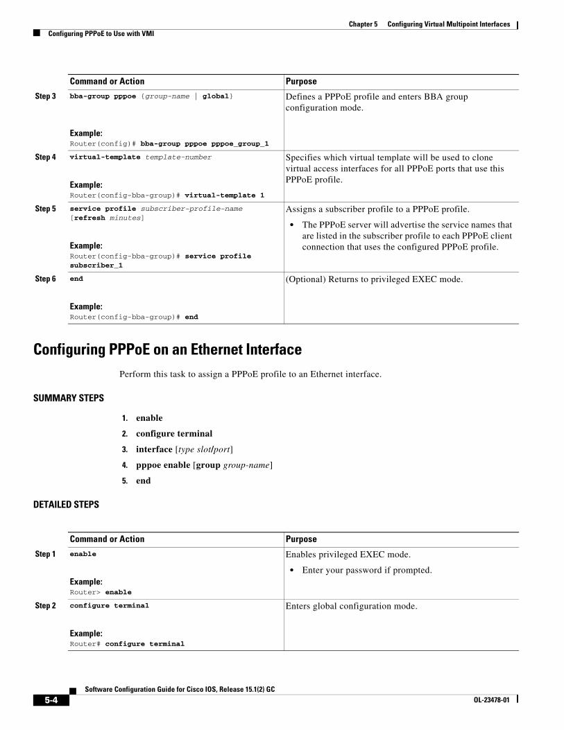
Configuring PPPoE on an Ethernet InterfacePerform this task to assign a PPPoE profile to an Ethernet interface.
Specifies which virtual template will be used to clone virtual access interfaces for all PPPoE ports that use this PPPoE profile.
Step 5 service profile subscriber-profile-name [refresh minutes]
Example:Router(config-bba-group)# service profile subscriber_1
Assigns a subscriber profile to a PPPoE profile.
• The PPPoE server will advertise the service names that are listed in the subscriber profile to each PPPoE client connection that uses the configured PPPoE profile.
Step 6 end
Example:Router(config-bba-group)# end
(Optional) Returns to privileged EXEC mode.
Command or Action Purpose
Command or Action Purpose
Step 1 enable
Example:Router> enable
Enables privileged EXEC mode.
• Enter your password if prompted.
Step 2 configure terminal
Example:Router# configure terminal
Enters global configuration mode.
5-4Software Configuration Guide for Cisco IOS, Release 15.1(2) GC
OL-23478-01
Chapter 5 Configuring Virtual Multipoint InterfacesConfiguring PPPoE to Use with VMI
Configuring a Virtual Template Interface for use with VMIThe virtual template interface is used to dynamically clone configurations for each virtual-access interface created for a VMI neighbor.
Perform this task to create a virtual template interface.
Specifies an interface type and enters interface configuration mode. Valid interfaces include the following interface types:
• Fast Ethernet interface
• Ethernet
• Fast Ethernet
• Gigabit Ethernet
• VLAN or VLAN subinterface
Step 4 pppoe enable [group group-name]
Example:Router(config-if)# pppoe enable group pppoe_group_1
Enables PPPoE sessions on the interface or subinterface.
Step 5 end
Example:Router(config-if)# end
(Optional) Exits the configuration mode and returns to privileged EXEC mode.
Command or Action Purpose
5-5Software Configuration Guide for Cisco IOS, Release 15.1(2) GC
OL-23478-01
Chapter 5 Configuring Virtual Multipoint InterfacesConfiguring PPPoE to Use with VMI
Detailed Steps
Command or Action Purpose
Step 1 enable
Example:Router> enable
Enables privileged EXEC mode.
• Enter your password if prompted.
Step 2 configure terminal
Example:Router# configure terminal
Enters global configuration mode.
Step 3 no virtual template subinterface
Example:Router# no virtual template subinterface
Disables the virtual template on the subinterface.
Step 4 policy-map policy-map-name
Example:Router(config-pmap)# policy-map FQ
Enters policy map configuration mode and creates, or modifies, a policy map that can be attached to one or more interfaces to specify a service policy.
Step 5 class class-default
Example:Router(config-pmap)# class class-default
Specifies the name of the class whose policy you want to create, or change, or specifies the default class (commonly known as the class-default class) before you configure its policy.
Step 6 fair-queue
Example:Router(config-pmap)# fair-queue
Enables Weighted Fair Queueing (WFQ) in the policy-map.
Step 7 exit
Example:Router(config-pmap)# exitRouter(config)#
Exits the current mode and returns to configuration mode.
ip unnumbered vmi1keepalive 60 20service-policy output FQ
!end
Configuring VMIVMI provides services that map outgoing packets to the appropriate PPPoE sessions based on the next-hop forwarding address for that packet.
Creates the physical subinterface to be associated with VMI on the router.
Step 6 end
Example:Router(config-if)# end
(Optional) Exits the configuration mode and returns to privileged EXEC mode.
5-8Software Configuration Guide for Cisco IOS, Release 15.1(2) GC
OL-23478-01
Chapter 5 Configuring Virtual Multipoint InterfacesUnderstanding Multicast Support for VMI
VMI in Aggregate Mode for IPv4
The following example shows the configuration of VMI in aggregate mode for IPv4.
interface Virtual-Template1 ip unnumbered vmi1 service-policy output FQ!interface vmi1 ip address 2.2.2.1 255.255.255.0 physical-interface FastEthernet0/0!
VMI in Aggregate Mode for IPv4 and IPv6
The following example shows the configuration of VMI in aggregate mode for IPv4 and IPv6.
interface Virtual-Template1 ip unnumbered vmi1 ipv6 enable service-policy output FQ!interface vmi1 ip address 2.2.2.1 255.255.255.0 ipv6 enable physical-interface FastEthernet0/0!
Understanding Multicast Support for VMIVMI operates in aggregate mode by default: All of the virtual-access interfaces created by PPPoE sessions are aggregated logically under the configured VMI. Applications above Layer 2 (L2), such as Enhanced Interior Gateway Routing Protocol (EIGRP) and OSPFv3, should be defined only on VMI. Packets sent to VMI are forwarded to the correct virtual-access interface(s). Aggregate mode VMIs operate in Non-Broadcast Multiple Access (NBMA) mode. Multicast traffic is forwarded only to the NBMA neighbors where a listener for that group is present.
Note Only IPv4 is supported for NBMA multicasting.
If you are running multicast applications that require virtual-access interfaces to be exposed to applications above L2 directly, you can configure VMI to operate in bypass mode. Most multicast applications require that the virtual-access interfaces be exposed directly to routing protocols in order for the multicast Reverse Path Forwarding (RPF) to operate as expected. When you use the bypass mode, you must define a VMI to handle cross-layer signals such as neighbor up, neighbor down, and metrics. Applications will be aware of the actual underlying virtual-access interfaces, and will send packets to them directly. Operating VMI in bypass mode can cause databases in the applications to be larger than normally expected because knowledge of more interfaces is required for normal operation.
This section identifies the recommended modes and tasks for working with multicast:
• Using Bypass Mode, page 5-10
• Enabling Multicast Support on a VMI, page 5-10
• Showing VMI Neighbors, page 5-12
5-9Software Configuration Guide for Cisco IOS, Release 15.1(2) GC
OL-23478-01
Chapter 5 Configuring Virtual Multipoint InterfacesUnderstanding Multicast Support for VMI
Using Bypass ModeUsing bypass mode is recommended for multicast applications.
In bypass mode, the virtual-access interfaces are directly exposed to applications running above L2. In bypass mode, you must still define a VMI because VMI continues to manage presentation of cross-layer signals, such as, neighbor up, neighbor down, and metrics. However, applications will still be aware of the actual underlying virtual-access interfaces and send packets to them directly.
Using bypass mode can cause databases in the applications to be larger because knowledge of more interfaces are required for normal operation.
Enabling Multicast Support on a VMI
Perform this task to enable bypass mode on a VMI and override the default aggregation that occurs on VMI. This configuration assumes that you have already configured a virtual template and appropriate PPPoE sessions for VMI.
After you enter the enable bypass mode, Cisco recommends that you copy the running configuration to Non-Volatile Random Access Memory (NVRAM) because the default mode of operation for VMI is to logically aggregate the virtual-access interfaces.
SUMMARY STEPS
1. enable
2. configure terminal
3. interface vmi number
4. mode bypass
5. exit
DETAILED STEPS
Command or Action Purpose
Step 1 enable
Example:Router> enable
Enables privileged EXEC mode.
• Enter your password if prompted.
Step 2 configure terminal
Example:Router# configure terminal
Enters global configuration mode.
Step 3 interface vmi number
Example:Router(config-if)# interface vmi1
Enters interface configuration mode and relates a VMI interface.
5-10Software Configuration Guide for Cisco IOS, Release 15.1(2) GC
OL-23478-01
Chapter 5 Configuring Virtual Multipoint InterfacesUnderstanding Multicast Support for VMI
Examples
VMI is required to have IP addresses assigned for VMI to work even though it will be shown as down/down when in bypass mode.
VMI in Bypass Mode for IPv6
The following example shows the configuration of VMI in bypass mode for IPv6.
Table 5-1 describes the significant fields shown in the show vmi neighbors detail command display.
Table 5-1 show vmi neighbors detail Field Descriptions
Field Description
Interface The interface number
IPv6 Address IPv6 address of the neighbor
IPv4 Address IPv4 address of the neighbor
Uptime How long the interface has been up in hh:mm:ss format
Output pkts Number of outgoing packets during the recorded up time
Input pkts Number of incoming packets during the recorded up time
Metric Data The metric data statistics include the following types of information:
• Total rcvd: The total number of packets received on the interface
• Avg arrival rate: The average arrival rate for each packet in milliseconds
• CURRENT: The current values for the following statistics: metric data rate (MDR), Credit Data Rate (CDR), Latency (Lat), Resource (Res), RLQ (RLQ), and the load
• MDR: The maximum, minimum, and average metric data rate
• CDR: The maximum, minimum, and average credit data rate
• Latency: The maximum, minimum, and average latency
• Resource: The maximum, minimum, and average resource
• RQL: The maximum, minimum, and average RQL
• Load: The maximum, minimum, and average load
Transport The routing protocol, in this case–PPPoE
Session ID The identifier of VMI session
INTERFACE STATS A series of statistics collected on the interface and shows for each of VMI, virtual access interface, and the physical interface. For each interface, statistics display indicating the number of packets in the input and output queues and the number of packets dropped from each queue.
5-13Software Configuration Guide for Cisco IOS, Release 15.1(2) GC
OL-23478-01
Chapter 5 Configuring Virtual Multipoint InterfacesUnderstanding Multicast Support for VMI
PPPoE Flow Control Stats
• The statistics collected for PPPoE credit flow.
• Local Credits: The number of credits belonging to the node
• Peer Credits: The number of credits belonging to the peer
• Scalar Value: The credit grant in bytes specified by the radio
• Credit Grant Threshold: The number of credits below which the peer needs to dip before this node sends an in-band or out-of-band grant
• Credit Starved Packets: The number of packets dropped or queued due to insufficient credits from the peer
• Max Credits per grant: 65534
• PADG Seq Num: The sequence number for the PPPoE packet discovery grant
• PADG Timer index: The timer index for the PPPoE packet discovery grant
• PADG last rcvd Seq Num: The sequence number for the previously received PPPoE packet discovery grant
• PADG last nonzero Seq Num: The sequence number for the last non-zero PPPoE packet discovery grant
• PADG last nonzero rcvd amount: The received amount in the last non-zero PPPoE packet discovery grant
• PADG Timers: The PPPoE packet discovery grant timers
• PADG xmit: numberic rcvd: The number of PPPoE packet discovery grants transmitted and received
• PADC xmit: 133 rcvd: 133: The number of PPPoE packet discovery grant confirmations transmitted and receivedPADQ xmit: 0 rcvd: The number of PPPoE packet discovery quality grants transmitted and received.
Table 5-1 show vmi neighbors detail Field Descriptions (continued)
Field Description
5-14Software Configuration Guide for Cisco IOS, Release 15.1(2) GC
OL-23478-01
Chapter 5 Configuring Virtual Multipoint InterfacesUnderstanding Multicast Support for VMI
!!bba-group pppoe pppoe-group1virtual-template 1service profile router1!!interface Loopback100no ip addressipv6 address 100:100:100:100:100::/100 eui-64ipv6 ospf network point-to-point!interface Ethernet0/0no ip addresspppoe enable group pppoe-group1
5-15Software Configuration Guide for Cisco IOS, Release 15.1(2) GC
OL-23478-01
Chapter 5 Configuring Virtual Multipoint InterfacesUnderstanding Multicast Support for VMI
!interface Virtual-Template1no ip addressipv6 enableservice-policy output FQ
!interface vmi1ip address 1.1.1.1 255.255.255.0ipv6 enableipv6 ospf network manetipv6 ospf 100 area 0physical-interface Ethernet0/0!ip forward-protocol nd!!no ip http serverno ip http secure-server!ipv6 router ospf 100router-id 1.1.1.1log-adjacency-changestimers spf 1 1redistribute connected!!control-plane!line con 0exec-timeout 0 0logging synchronousline aux 0line vty 0 4login!exception data-corruption buffer truncateend
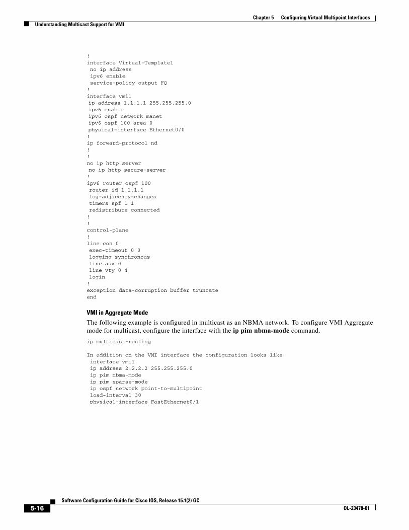
VMI in Aggregate Mode
The following example is configured in multicast as an NBMA network. To configure VMI Aggregate mode for multicast, configure the interface with the ip pim nbma-mode command.
ip multicast-routing
In addition on the VMI interface the configuration looks like interface vmi1 ip address 2.2.2.2 255.255.255.0 ip pim nbma-mode ip pim sparse-mode ip ospf network point-to-multipoint load-interval 30 physical-interface FastEthernet0/1
5-16Software Configuration Guide for Cisco IOS, Release 15.1(2) GC
OL-23478-01
Chapter 5 Configuring Virtual Multipoint InterfacesUnderstanding Multicast Support for VMI
The following example is VMI on an OSPF network:
Building configuration...
Current configuration : 6121 bytes!version 15.1service timestamps debug datetime msecservice timestamps log datetime msecno service password-encryption!hostname mcrtr4!boot-start-markerboot-end-marker!logging message-counter sysloglogging buffered 51200 warnings!no aaa new-model!ip source-route!!ip cef!!ip domain name yourdomain.comip multicast-routing ip multicast cache-headersno ipv6 cefsubscriber authorization enable!!multilink bundle-name authenticated!username lab privilege 15 secret 5 $1$v1bl$B5KD7o3jVKYqfoKoS0FUJ1!!archive log config hidekeys!!bba-group pppoe chan virtual-template 1 service profile chan!!interface Loopback0 ip address 15.15.15.15 255.255.255.255 ip broadcast-address 0.0.0.0!
interface FastEthernet0/0 description $ETH-LAN$$ETH-SW-LAUNCH$$INTF-INFO-FE 0/0$ ip address 1.1.1.2 255.255.255.0 ip broadcast-address 0.0.0.0 ip pim sparse-mode ip igmp version 3 duplex auto speed auto
5-17Software Configuration Guide for Cisco IOS, Release 15.1(2) GC
OL-23478-01
Chapter 5 Configuring Virtual Multipoint InterfacesUnderstanding Multicast Support for VMI
!interface FastEthernet0/1 no ip address ip broadcast-address 0.0.0.0 duplex auto speed auto pppoe enable group chan!interface FastEthernet0/0/0!interface FastEthernet0/0/1!interface FastEthernet0/0/2!interface FastEthernet0/0/3interface FastEthernet0/1/0 no ip address ip broadcast-address 0.0.0.0 duplex auto speed auto!interface Virtual-Template1 ip unnumbered vmi1 no peer default ip address fair-queue!interface Vlan1 ip address 10.15.60.53 255.255.255.0!interface vmi1 ip address 2.2.2.2 255.255.255.0 ip pim nbma-mode ip pim sparse-mode ip ospf network point-to-multipoint load-interval 30 physical-interface FastEthernet0/1!router ospf 1 log-adjacency-changes redistribute connected subnets redistribute static network 1.1.1.0 0.0.0.255 area 0 network 2.2.2.0 0.0.0.255 area 0!ip forward-protocol ndip http serverip http access-class 23ip http authentication localip http secure-serverip http timeout-policy idle 60 life 86400 requests 10000!!ip pim rp-address 16.16.16.16ip pim register-source vmi1!access-list 23 permit 10.10.10.0 0.0.0.7access-list 110 permit ip any any!!control-plane!!mgcp fax t38 ecm!
5-18Software Configuration Guide for Cisco IOS, Release 15.1(2) GC
OL-23478-01
Chapter 5 Configuring Virtual Multipoint InterfacesUnderstanding Multicast Support for VMI
!line con 0 exec-timeout 0 0 login localline aux 0line vty 0 4 access-class 23 inprivilege level 15 login local transport input telnet sshline vty 5 15 access-class 23 in privilege level 15 login local transport input telnet ssh!exception data-corruption buffer truncatescheduler allocate 20000 1000end
Configuring Two VMIs
The following example shows a configuration that includes two VMIs, each having different service names.
...<output truncated>...!subscriber authorization enable!ipv6 unicast-routing policy-map FQ class class-default fair-queue!!bba-group pppoe router1_ground virtual-template 1!bba-group pppoe router1_satellite virtual-template 2!!interface Ethernet0/0 pppoe enable group router1_ground!interface Ethernet0/1 pppoe enable group router1_satellite...<output truncated>...!interface Virtual-Template1 ip unnumbered vmi1 load-interval 30 no peer default ip address no keepalive service-policy output FQ
5-19Software Configuration Guide for Cisco IOS, Release 15.1(2) GC
!interface Virtual-Template2 ip unnumbered vmi2 load-interval 30 no peer default ip address no keepalive service-policy output FQ!interface vmi1 description ground connection ip address 2.2.2.1 255.255.255.0 physical-interface Ethernet0/0!interface vmi2 description satellite connection ip address 2.2.3.1 255.255.255.0 physical-interface Ethernet0/1!router eigrp 1 network 2.2.2.0 0.0.0.255 network 2.2.3.0 0.0.0.255 auto-summary!!no ip http server!!control-plane!!line con 0 exec-timeout 0 0 logging synchronousline aux 0line vty 0 4 login!end
Defining Multicast Routing in NBMA ModeMulticast is defined as a network group membership spanning the entire network. Multicast traffic is unidirectional from a source to a group of receivers. In both IPv4 and IPv6 architectures, a portion of the address space is reserved for multicast groups. Group addresses are requested to and assigned by IANA. See Table 5-2 for IPv4 examples.
Table 5-2 Assigned IPv4 Multicast Addresses
Addresses Usage
224.0.0.1 All Hosts
224.0.0.2 All Multicast Hosts
224.0.0.5 OSPF Routers
224.0.0.10 IGRP Routers
224.0.0.13 All PIM Routers
224.0.0.19 – 224.0.0.255 Unassigned
5-20Software Configuration Guide for Cisco IOS, Release 15.1(2) GC
OL-23478-01
Chapter 5 Configuring Virtual Multipoint InterfacesUnderstanding QoS Configuration for VMI
NBMA mode is achieved on a VMI aggregate interface. When operating in Multicast NBMA mode, only the Virtual Interfaces which are part of the multicast tree will receive multicast traffic.
Example:The following example shows configuration steps for interface vmi1:
Understanding QoS Configuration for VMIVMI supports full Modular QoS CLI (MQC) configurations. This includes remarking, shaping, and policing.
Note The QoS policy can only be applied to one outgoing interface the PPPoE session is traversing.
Examples
The following configuration examples include QoS features in use with a VMI. For more information about applying QoS features, see the following URL: http://www.cisco.com/en/US/partner/docs/ios/qos/configuration/guide/qos_mqc_ps6441_TSD_Products_Configuration_Guide_Chapter.html
class-map match-any chat match dscp af11 class-map match-any voice match dscp ef class-map match-any af23 match dscp af23 class-map match-any af31 match dscp af31 class-map match-any af33 match dscp af33 class-map match-any af42 match dscp af42 policy-map multiple_sessions class chat bandwidth 50 class voice bandwidth 100 class af23 bandwidth 150 class af31 bandwidth 200 class af33 bandwidth 250 class af42 bandwidth 300 int virtual-template 1 service-policy output multiple_sessions
5-21Software Configuration Guide for Cisco IOS, Release 15.1(2) GC
OL-23478-01
Chapter 5 Configuring Virtual Multipoint InterfacesUnderstanding QoS Configuration for VMI
Example: Placing the Policy on the Virtual Templateint virtual-template 1service-policy output police
5-22Software Configuration Guide for Cisco IOS, Release 15.1(2) GC
OL-23478-01
Software CoOL-23478-01
C H A P T E R 6
OSPFv3 Address Families
This chapter explains how to use OSPFv3 address families to route IPv6 packets over OSPFv3—using IPv4 or IPv6 addresses. This chapter also describes how to configure and use OSPFv3 address families in conjunction with Mobile Ad-hoc Networks (MANETs) and Radio Aware Routing (RAR).
This chapter includes the following major sections:
• Configuring OSPFv3 Address Families, page 6-1
• Working with Multiple Address Families, page 6-11
• Redistributing IPv4 Routes, page 6-12
• Verifying OSPFv3 Address Families Configuration and Operation, page 6-14
OSPFv3 is defined to support IPv6 unicast prefixes. The Internet draft, Support of Address Families in OSPFv3 (IETF RFC 5838), extends OSPFv3 to support multiple address families. Cisco IOS implemented this extension, which allows IPv4 unicast addresses to be supported. Coupled with the RAR feature and the OSPFv3 MANET feature (see the Chapter 5, “Configuring Virtual Multipoint Interfaces”), IPv4 routing can now be performed in MANETs. See Chapter 6, “OSPFv3 Address Families”.
Configuring OSPFv3 Address FamiliesThis section describes how to configure OSPFv3 Address Families for IPv6 and IPv4.
The Cisco OSPFv3 Address Families feature implements RFC 5838 and enables the ability to concurrently route IPv4 and IPv6 prefixes. The Cisco OSPFv3 Address Families feature is turned on in conjunction with the OSPFv3 MANET feature, which supports routing of IPv4 and IPv6 addresses and prefixes in mobile environments.
Configuring OSPFv3 Address Families is similar to configuring traditional IPv6 OSPFv3—the main difference being parameter usage in the CLI configuration commands. When configuring OSPFv3 Address Families, the new parameter ospfv3 replaces the deprecated ipv6 ospf parameter. See Appendix A, “Command Reference” for complete command reference information.
Working with IPv6 and OSPFv3 involves the following tasks:
1. Enabling IPv6, page 6-2
2. Enabling IPv6 on the Interface, page 6-3
3. Configuring OSPFv3 for a Unicast Address Family, page 6-3
6-1nfiguration Guide for Cisco IOS, Release 15.1(2) GC
Enabling IPv6 on the InterfaceThis task explains how to enable IPv6 on an interface. This is a prerequisite to configuring OSPFv3 on the interface. IPv6 is disabled on the interface by default.
SUMMARY STEPS
1. enable
2. configure terminal
3. interface [type number]
4. ipv6 enable
5. exit
DETAILED STEPS
Configuring OSPFv3 for a Unicast Address FamilyPerform one of the following tasks:
• Configuring OSPFv3 for an IPv6 Unicast Address Family, page 6-4
• Configuring OSPFv3 for an IPv4 Unicast Address Family, page 6-7
Command or Action Purpose
Step 1 enable
Example:Router> enable
Enables privileged EXEC mode.
• Enter your password if prompted.
Step 2 configure terminal
Example:Router# configure terminal
Enters global configuration mode.
Step 3 interface [type number]
Example:Router(config)# interface ethernet 0/0
Specifies an interface type and number and places the router in interface configuration mode.
Step 4 ipv6 enable
Example:Router(config-if)# ipv6 enable
Enables IPv6 processing on an interface that has not been configured with an explicit IPv6 address.
Step 5 exit
Example:Router(config-if)# exit
Exits global configuration mode and returns the router to privileged EXEC mode.
6-3Software Configuration Guide for Cisco IOS, Release 15.1(2) GC
version 15.1!hostname Router1!boot-start-markerboot-end-marker!no aaa new-modelip cef!ipv6 unicast-routing!interface Ethernet0/0 ipv6 enable ospfv3 6 area 0 ipv6!interface Ethernet0/1 no ip address shutdown!interface Ethernet0/2 no ip address shutdown!interface Ethernet0/3 no ip address shutdown!ip forward-protocol nd!no ip http server!router ospfv3 6 router-id 6.6.6.6 log-adjacency-changes address-family ipv6 unicast exit-address-family!control-plane!!line con 0line aux 0line vty 0 4 login!end
6-5Software Configuration Guide for Cisco IOS, Release 15.1(2) GC
version 15.1!hostname Router1!boot-start-markerboot-end-marker!no aaa new-modelip cef!ipv6 unicast-routing!interface Ethernet0/0 ip address 64.1.1.1 255.255.255.0 ipv6 enable ospfv3 4 area 0 ipv4! interface Ethernet0/1 no ip address shutdown!interface Ethernet0/2 no ip address shutdown!interface Ethernet0/3 no ip address shutdown!ip forward-protocol nd!no ip http server!router ospfv3 4 router-id 4.4.4.4 log-adjacency-changes address-family ipv4 unicast exit-address-family!control-plane!!line con 0line aux 0line vty 0 4 login!end
6-8Software Configuration Guide for Cisco IOS, Release 15.1(2) GC
Places the router in address family configuration mode for IPv4 address family.
Step 6 exit
Example:Router (config-router-af)# exit
Exits global configuration mode and returns the router to privileged EXEC mode.
6-10Software Configuration Guide for Cisco IOS, Release 15.1(2) GC
OL-23478-01
Chapter 6 OSPFv3 Address FamiliesWorking with Multiple Address Families
Working with Multiple Address FamiliesYou can run Address Families OSPFv3 for IPv4 and IPv6 simultaneously on one interface.
Note To configure OSPFv3 for IPv4 and IPv6 simultaneously—with MANET and RAR features included, use tasks from this chapter and Chapter 6, “OSPFv3 Address Families” The following example shows how to do this.
Example
version 15.1!hostname Router1!boot-start-markerboot-end-marker!no aaa new-model!ip cefipv6 unicast-routing!subscriber authorization enable!subscriber profile Dargo7 pppoe service manet_radio!!multilink bundle-name authenticated!no virtual-template subinterface!bba-group pppoe Group1 virtual-template 1 service profile Dargo7!interface Ethernet0/0 no ip address pppoe enable group Group1!interface Ethernet0/1 no ip address shutdown!interface Ethernet0/2 no ip address shutdown!interface Ethernet0/3 no ip address shutdown!interface Virtual-Template1 no ip address ipv6 enable no peer default ip address no keepalive!
6-11Software Configuration Guide for Cisco IOS, Release 15.1(2) GC
Redistributing IPv4 RoutesShould you need to redistribute IPv4 routes between OSPFv3 Address Families and OSPFv2, be aware of common issues when redistributing IPv4 routes between OSPF processes as documented here: http://www.cisco.com/en/US/tech/tk365/technologies_white_paper09186a0080531fd2.shtml
Note For detailed command reference information, see Appendix A, “Command Reference”.
Example:The following example shows how to redistribute IPv4 routes from OSPFv2 process 22 into OSPFv3 Address Families process 4:
Router (config)#router ospfv3 4Router (config-router)#router-id 4.4.4.4Router (config-router)#address-family ipv4 unicastRouter (config-router-af)#redistribute ? bgp Border Gateway Protocol (BGP) connected Connected eigrp Enhanced Interior Gateway Routing Protocol (EIGRP) isis ISO IS-IS iso-igrp IGRP for OSI networks lisp Locator ID Separation Protocol (LISP) mobile Mobile routes odr On Demand stub Routes
6-12Software Configuration Guide for Cisco IOS, Release 15.1(2) GC
ospf Open Shortest Path First (OSPF) ospfv3 OSPFv3 rip Routing Information Protocol (RIP) static Static routes Router (config-router-af)#redistribute ospf ? <1-65535> Process ID Router (config-router-af)#redistribute ospf 22 ? match Redistribution of OSPF routes metric Metric for redistributed routes metric-type OSPF/IS-IS exterior metric type for redistributed routes route-map Route map reference tag Set tag for routes redistributed into OSPF vrf VPN Routing/Forwarding Instance <cr> Router (config-router-af)#redistribute ospf 22
Example:The following example shows how to redistribute IPv4 routes from OSPFv3 Address Families process 4 into OSPFv2 process 22:
Router (config)#router ospf 22Router (config-router)#redistribute ? bgp Border Gateway Protocol (BGP) connected Connected eigrp Enhanced Interior Gateway Routing Protocol (EIGRP) isis ISO IS-IS iso-igrp IGRP for OSI networks lisp Locator ID Separation Protocol (LISP) maximum-prefix Maximum number of prefixes redistributed to protocol mobile Mobile routes odr On Demand stub Routes ospf Open Shortest Path First (OSPF) ospfv3 OSPFv3 rip Routing Information Protocol (RIP) static Static routes Router (config-router)#redistribute ospfv3 ? <1-65535> Process ID Router (config-router)#redistribute ospfv3 4 ? match Redistribution of OSPF routes metric Metric for redistributed routes metric-type OSPF/IS-IS exterior metric type for redistributed routes nssa-only Limit redistributed routes to NSSA areas route-map Route map reference subnets Consider subnets for redistribution into OSPF tag Set tag for routes redistributed into OSPF <cr> Router (config-router)#redistribute ospfv3 4 subnets ? match Redistribution of OSPF routes metric Metric for redistributed routes metric-type OSPF/IS-IS exterior metric type for redistributed routes nssa-only Limit redistributed routes to NSSA areas route-map Route map reference tag Set tag for routes redistributed into OSPF <cr> Router (config-router)#redistribute ospfv3 4 subnets
6-13Software Configuration Guide for Cisco IOS, Release 15.1(2) GC
Verifying OSPFv3 Address Families Configuration and OperationYou can use any combination of the commands listed in this section to check the operation status of OSPFv3 for Address Families. See Appendix A, “Command Reference” for detailed command reference.
Note You must be in privileged EXEC mode to enter the command listed in this section.
The show ospfv3 command can be used to show general information about the OSPFv3 Address Family router process.
Router# show ospfv3 Routing Process "ospfv3 4" with ID 4.4.4.4 Supports IPv4 Address Family Event-log enabled, Maximum number of events: 1000, Mode: cyclic Initial SPF schedule delay 1000 msecs Minimum hold time between two consecutive SPFs 2000 msecs Maximum wait time between two consecutive SPFs 2000 msecs Minimum LSA interval 5 secs Minimum LSA arrival 1000 msecs LSA group pacing timer 240 secs Interface flood pacing timer 33 msecs Retransmission pacing timer 66 msecs Number of external LSA 0. Checksum Sum 0x000000 Number of areas in this router is 1. 1 normal 0 stub 0 nssa Graceful restart helper support enabled Reference bandwidth unit is 100 mbps
Command or Action Purpose
show run
Example:Router# show run
Verify a configuration.
show ospfv3
Example:Router# show ospfv3
Displays general information about all OSPFv3 routing processes.
show ospfv3 neighbor
Example:Router# show ospfv3 neighbor
Displays OSPFv3 neighbor information per routing process.
show ospfv3 neighbor detail
Example:Router# show ospfv3 neighbor detail
Displays a detailed list of all neighbors.
show ospfv3 interface [interface-type interface-number]
Example:show ospfv3 interface e0/0
Displays all OSPFv3 routing information for an interface.
6-14Software Configuration Guide for Cisco IOS, Release 15.1(2) GC
Relay willingness value is 128 Pushback timer value is 2000 msecs Relay acknowledgement timer value is 1000 msecs LSA cache Disabled : current count 0, maximum 1000 ACK cache Disabled : current count 0, maximum 1000 Selective Peering is not enabled Hello requests and responses will be sent multicast Area BACKBONE(0) (Inactive) Number of interfaces in this area is 1 SPF algorithm executed 0 times Number of LSA 0. Checksum Sum 0x000000 Number of DCbitless LSA 0 Number of indication LSA 0 Number of DoNotAge LSA 0 Flood list length 0
Router# show ospfv3 neighbor
OSPFv3 Router with ID (4.4.4.4) (Process ID 4)
Neighbor ID Pri State Dead Time Interface ID Interface2.2.2.2 0 FULL/ - 00:00:19 3 Ethernet0/0
Router# show ospfv3 interface e0/0Ethernet0/0 is up, line protocol is up Link Local Address FE80::A8BB:CCFF:FE01:5500, Interface ID 3 Area 0, Process ID 100, Instance ID 0, Router ID 4.4.4.4 Network Type MANET, Cost: 10 (dynamic), Cost Hysteresis: Disabled Cost Weights: Throughput 100, Resources 100, Latency 100, L2-factor 100 Transmit Delay is 1 sec, State POINT_TO_MULTIPOINT Timer intervals configured, Hello 30, Dead 120, Wait 120, Retransmit 5 Hello due in 00:00:01 Graceful restart helper support enabled Index 1/1/1, flood queue length 0 Next 0x0(0)/0x0(0)/0x0(0) Last flood scan length is 1, maximum is 1 Last flood scan time is 0 msec, maximum is 0 msec Neighbor Count is 1, Adjacent neighbor count is 1 Adjacent with neighbor 2.2.2.2 Suppress hello for 0 neighbor(s) Incremental Hello is enabled Local SCS number 1 Relaying enabled
6-15Software Configuration Guide for Cisco IOS, Release 15.1(2) GC
6-16Software Configuration Guide for Cisco IOS, Release 15.1(2) GC
OL-23478-01
Software CoOL-23478-01
C H A P T E R 7
Configuring OSPFv3 for MANETs
This chapter describes how to configure OSPFv3 in a Mobile Ad Hoc Network (MANET) for use with non-cooperative radios.
Configuring OSPFv3 for MANETs is very similar to configuring traditional OSPFv3. Many of the requirements for traditional OSPFv3 are also required for OSPFv3 for MANETs with non-cooperative radios. The only additional mandatory step is configuring the network type to be “MANET”
This chapter includes the following sections:
• Understanding How OSPFv3 Works with MANETs, page 7-1
• Configuring OSPFv3 in MANETs for Radio Aware Routing, page 7-7
• Verifying OSPFv3 MANET Configuration and Operation, page 7-16
Understanding How OSPFv3 Works with MANETsCisco IOS implements the extensions to OSPFv3 as defined in draft-chandra-ospf-manet-ext-02 to optimize the use of OSPFv3 with MANETs. The result is a well-understood routing protocol used in a network topology that is constantly changing and where bandwidth is limited. This is accomplished in several ways:
• Tight coupling of OSPFv3 with “cooperative” radios to in order to provide faster convergence and re-convergence through neighbor presence indications and to determine accurate, real-time link metric costs. This is “radio-aware routing”.
• Minimization of OSPFv3 packet size by implementing the “incremental Hello” feature.
• Minimization of OSPFv3 packet transmissions by caching multicast Link-State Advertisements (LSAs).
• Implementation of the Optimized Flooding (Overlapping Relay) functionality to minimize the number of flooded LSAs.
• Implementation of selective peering to reduce the OSPF network overhead by minimizing the number of redundant full adjacencies an OSPF node maintains.
OSPFv3 is best utilized in conjunction with cooperative radios. This is accomplished by using the Virtual Multipoint Interface (VMI). For more information, see Chapter 5, “Configuring Virtual Multipoint Interfaces.” OSPFv3 can also be used without cooperative radios, albeit with limited improvements. This section describes how to configure Cisco IOS OSPFv3 MANET with and without cooperative radios.
7-1nfiguration Guide for Cisco IOS, Release 15.1(2) GC
Chapter 7 Configuring OSPFv3 for MANETsUnderstanding How OSPFv3 Works with MANETs
When working with IPv6 and OSPFv3, you perform the following tasks:
• Enable IPv6 routing, page 2
• Enable IPv6 on the interface, page 3
• Configure the OSPFv3 process, page 4
• Configure OSPFv3 in MANETs on the interface, page 5
Enabling IPv6 RoutingThis task explains how to enable IPv6 packet forwarding and IPv6 routing. Both are disabled by default.
SUMMARY STEPS
1. enable
2. configure terminal
3. ipv6 unicast-routing
4. exit
DETAILED STEPS
Command or Action Purpose
Step 1 enable
Example:Router> enable
Enables privileged EXEC mode.
• Enter your password if prompted.
Step 2 configure terminal
Example:Router# configure terminal
Enters global configuration mode.
Step 3 ipv6 unicast-routing
Example:Router(config)# ipv6 unicast-routing
Enables the forwarding of IPv6 unicast datagrams.
Step 4 exit
Example:Router(config)# exit
Exits global configuration mode, and returns the router to privileged EXEC mode.
7-2Software Configuration Guide for Cisco IOS, Release 15.1(2) GC
OL-23478-01
Chapter 7 Configuring OSPFv3 for MANETsUnderstanding How OSPFv3 Works with MANETs
Enabling IPv6 on the InterfaceThis task explains how to enable IPv6 on an interface. This is a pre-requisite to configuring OSPFv3 on the interface. IPv6 is disabled on the interface by default.
SUMMARY STEPS
1. enable
2. configure terminal
3. interface [type number]
4. ipv6 enable
5. exit
DETAILED STEPS
Command or Action Purpose
Step 1 enable
Example:Router> enable
Enables privileged EXEC mode.
• Enter your password if prompted.
Step 2 configure terminal
Example:Router# configure terminal
Enters global configuration mode.
Step 3 interface [type number]
Example:Router(config)# interface ethernet 0/0
Specifies an interface type and number, and places the router in interface configuration mode.
Step 4 ipv6 enable
Example:Router(config-if)# ipv6 enable
Enables IPv6 processing on an interface that has not been configured with an explicit IPv6 address.
Step 5 exit
Example:Router(config-if)# exit
Exits global configuration mode, and returns the router to privileged EXEC mode.
7-3Software Configuration Guide for Cisco IOS, Release 15.1(2) GC
OL-23478-01
Chapter 7 Configuring OSPFv3 for MANETsUnderstanding How OSPFv3 Works with MANETs
Configuring the OSPFv3 ProcessThis task explains how to configure the OSPFv3 process.
SUMMARY STEPS
1. enable
2. configure terminal
3. router ospfv3 [process-id]
4. router-id [OSPF router-id in IP address format]
5. address-family ipv6
6. exit
DETAILED STEPS
Command or Action Purpose
Step 1 enable
Example:Router> enable
Enables privileged EXEC mode.
• Enter your password if prompted.
Step 2 configure terminal
Example:Router# configure terminal
Enters global configuration mode.
Step 3 router ospfv3 [process-id]
Example:Router(config)# router ospfv3 6
Enables Open Shortest Path First (OSPF) for IPv6 router configuration mode.
Step 4 router-id [OSPF router-id in IP address format]
Example:Router(config-rtr)# router-id 10.1.1.1
Enables the use of a fixed router ID.
Step 5 address-family ipv6
Example:Router(config-rtr)# address-family ipv6
Enables the address family for IPv6.
Step 6 exit
Example:Router(config-rtr)# exit
Exits global configuration mode, and returns the router to privileged EXEC mode.
7-4Software Configuration Guide for Cisco IOS, Release 15.1(2) GC
OL-23478-01
Chapter 7 Configuring OSPFv3 for MANETsUnderstanding How OSPFv3 Works with MANETs
Configuring OSPFv3 in MANETs on the InterfaceThis task explains how to configure the OSPFv3 process.
SUMMARY STEPS
1. enable
2. configure terminal
3. interface [type number]
4. ospfv3 [process-id] area area-id ipv6 [instance instance-id]
5. ospfv3 [process-id] network manet
6. exit
DETAILED STEPS
Command or Action Purpose
Step 1 enable
Example:Router> enable
Enables privileged EXEC mode.
• Enter your password if prompted.
Step 2 configure terminal
Example:Router# configure terminal
Enters global configuration mode.
Step 3 interface [type number]
Example:Router(config)# interface vmi1
Configures an interface type.
Step 4 ospfv3 [process-id] area area-id ipv6 [instance instance-id]
Example:(Router-if)# ospfv3 6 area 0 ipv6
Enables OSPFv3 for IPv6 router configuration mode.
NOTE: The instance number automatically defaults to 0 for ipv6.
Step 5 ospfv3 [process-id] network manet
Example:Router(config-if)# ospfv3 6 network manet
Configures the OSPFv3 network type to MANET.
Step 6 exit
Example:Router(config-if)# exit
Exits global configuration mode, and returns the router to privileged EXEC mode.
7-5Software Configuration Guide for Cisco IOS, Release 15.1(2) GC
OL-23478-01
Chapter 7 Configuring OSPFv3 for MANETsUnderstanding How OSPFv3 Works with MANETs
EXAMPLE
version 12.4!hostname Router1!boot-start-markerboot-end-marker!no aaa new-modelip cef!ipv6 unicast-routingipv6 cef !interface vmi1 no ip address ipv6 enable ospfv3 network manet ospfv3 6 area 0 ipv6! interface Ethernet0/1 no ip address shutdown!interface Ethernet0/2 no ip address shutdown!interface Ethernet0/3 no ip address shutdown!ip forward-protocol nd!no ip http server!router ospfv3 6 router-id 1.1.1.1 address-family ipv6 unicastlog-adjacency-changes
!control-plane!!line con 0line aux 0line vty 0 4 login!end
7-6Software Configuration Guide for Cisco IOS, Release 15.1(2) GC
OL-23478-01
Chapter 7 Configuring OSPFv3 for MANETsConfiguring OSPFv3 in MANETs for Radio Aware Routing
Configuring OSPFv3 in MANETs for Radio Aware RoutingThis section describes how to configure OSPFv3 in MANETs for use with cooperative radios. A cooperative radio is attached to the VMI. For more information on VMI, see Chapter 5, “Configuring Virtual Multipoint Interfaces.” In order for OSPFv3 to take advantage of the radio feedback, OSPFv3 MANET must be configured on the VMI interface. By default, VMI automatically utilizes the neighbor presence and link metric information from the radio.
When configuring OSPFv3 in MANETs for Radio Aware Routing (RAR), you must fine tune radio aware routing metrics for OSPFv3 MANET. For information on fine tuning radio aware routing metrics for OSPFv3 MANET, see page 8.
For basic configuration tasks see the Configuring OSPFv3 in MANETs on the Interface section. The difference is OSPFv3 MANET is configured on the VMI interface.
EXAMPLE
The following is an example of configuration:
version 12.4!hostname Router1!boot-start-markerboot-end-marker!no aaa new-model!ip cefipv6 unicast-routingipv6 cefsubscriber authorization enable!subscriber profile pppoe_group_1 pppoe service manet_radio!!multilink bundle-name authenticated!no virtual-template subinterface!bba-group pppoe pppoe_group_1 virtual-template 1 service profile pppoe_group_1!interface vmi1 ip address 10.10.11.1 255.255.255.0 pppoe enable group pppoe_group_1!interface Ethernet0/1 no ip address shutdown!interface Ethernet0/2 no ip address shutdown!interface Ethernet0/3 no ip address shutdown!
7-7Software Configuration Guide for Cisco IOS, Release 15.1(2) GC
OL-23478-01
Chapter 7 Configuring OSPFv3 for MANETsConfiguring OSPFv3 in MANETs for Radio Aware Routing
interface Virtual-Template1 no ip address ipv6 enable no peer default ip address no keepalive!interface vmi1 no ip address ipv6 enable ospfv3 6 network manet ospfv3 6 area 0 ipv6 physical-interface vmi1!ip forward-protocol nd!router ospfv3 1!log-adjacency-changesaddress-family ipv6 unicastexit-address-family
!control-plane!line con 0 exec-timeout 0 0line aux 0line vty 0 4 login!end
Fine Tuning Radio Aware Routing Metrics for OSPFv3 MANETAs discussed in the “Understanding Link Quality Metrics Reporting for OSPFv3 and EIGRP with VMI Interfaces” section on page 4-5, the cooperative radio reports link quality metrics to the router that are used by OSPFv3 as link metrics. Two basic levels of configuration “fine tuning” can be made to adjust how these radio metrics are used by OSPFv3:
1. Configure how the radio-reported bandwidth, latency, resource and relative link quality metrics are converted to an OSPFv3 link cost.
2. Configure a hysteresis threshold on this resultant link cost in order to minimize the propagation of LSAs that report link metric changes.
OSPFv3 receives raw radio link data, and compute a composite. In computing these metrics, the following factors may be considered:
• Maximum Data Rate—the theoretical maximum data rate of the radio link, in bytes per second
• Current Data Rate—the current data rate achieved on the link, in bytes per second
• Latency—the transmission delay packets encounter, in milliseconds
• Resources—a percentage (0-100) that can represent the remaining amount of a resource (such as battery power)
• Relative Link Quality—a numeric value (0-100) representing relative quality, with 100 being the highest quality
7-8Software Configuration Guide for Cisco IOS, Release 15.1(2) GC
OL-23478-01
Chapter 7 Configuring OSPFv3 for MANETsConfiguring OSPFv3 in MANETs for Radio Aware Routing
Metrics can be weighted during the configuration process to emphasize or de-emphasize particular characteristics. For example, if throughput is a particular concern, the current data rate metric could be weighted so that it is factored more heavily into the composite metric. Similarly, a metric that is of no concern can be omitted from the composite calculation.
Link metrics can change rapidly, often by very small degrees, which can result in a flood of meaningless routing updates. In a worst case scenario, the network will churn almost continuously as it struggles to react to minor variations in link quality. To alleviate this concern, Cisco provides a tunable dampening mechanism that allows the user to configure threshold values. Any metric change that falls below the threshold is ignored.
A tunable hysteresis mechanism allows users to adjust the threshold to the routing changes that occur when the router receives a signal that a new peer has been discovered, or that an existing peer is unreachable. The tunable metric is weighted and is adjusted dynamically to account for the following characteristics:
• Current and Maximum Bandwidth
• Latency
• Resources
• Hysteresis
Individual weights can be deconfigured and all weights can be cleared so that the cost is set back to the default value for the interface type. Based on the routing changes that occur, cost can be determined by the application of these metrics.
The dynamic cost metric used for interfaces is computed based on the Layer 2 (L2) feedback to Layer 3 (L3), where the metric calculations are as follows:
For a dynamic cost to have the same cost as a default cost, all parameters must equal zero.
Each L2 feedback can contribute a cost in the range of 0 to 65535. To tune down this cost range, use the optional weight keyword in conjunction with the throughput, resources, latency, or L2-factor keyword. Each of these weights has a default value of 100 percent and can be configured in a range from 0 to 100. When 0 is configured for a specific weight, that weight does not contribute to the OSPF cost.
Because cost components can change rapidly, you may need to dampen the amount of changes in order to reduce network-wide churn. Use the optional hysteresis keyword with the threshold threshold-value keyword and argument to set a cost change threshold. Any cost change below this threshold is ignored.
You can use the hysteresis keyword to specify a hysteresis value based on the percentage of change of the currently stored value in the routing table for the peer.
Each time the router receives a new PADQ packet from the radio for a peer, a new cost will be calculated for it. The hysteresis keyword specifies the amount of change required before saving the new value.
The hysteresis percent calculated is performed as follows:
If the absolute value of (new_cost - saved_cost) is greater than (hysteresis_percent*saved_cost), then the new_cost will be saved.
7-9Software Configuration Guide for Cisco IOS, Release 15.1(2) GC
OL-23478-01
Chapter 7 Configuring OSPFv3 for MANETsConfiguring OSPFv3 in MANETs for Radio Aware Routing
Because cost components can change rapidly, it might be necessary to dampen the volume of changes to reduce network-wide churn. The recommended values for S2, S3, and S4 are based on network simulations that may reduce the rate of network changes. The recommended value for S1 is zero to eliminate this variable from the route cost calculation.
While each network might have unique characteristics that require different settings to optimize actual network performance, these are recommended values intended as a starting point for optimizing a OSPFv3 network. Table 1 lists the recommended value settings for OSPF cost metrics.
The overall link cost is computed using the following formula:
EXAMPLE
To illustrate these settings, the following example shows how OSPF cost metrics might be defined for a VMI interface with one type of radio:
Table 1 Recommended Value Settings for OSPF Cost Metrics
Setting Metric Description Default Value Recommended Value
S1 ospfv3 6 dynamic weight throughout 100 0
S2 ospfv3 6 dynamic weight resources 100 29
S3 ospfv3 6 dynamic weight latency 100 29
S4 ospfv3 6 dynamic weight L2-factor 100 29
7-10Software Configuration Guide for Cisco IOS, Release 15.1(2) GC
OL-23478-01
Chapter 7 Configuring OSPFv3 for MANETsUnderstanding OSPFv3 MANET Selective Peering
Understanding OSPFv3 MANET Selective PeeringThe purpose of selective peering is to reduce the OSPF network overhead by minimizing the number of redundant FULL adjacencies an OSPF node maintains. The basic premise is that adjacencies to nodes that do not provide additional reachability can be kept in a 2-WAY state. This reduces control-plane bandwidth utilization by reducing database exchanges and routing updates.
Note Dataplane connectivity is in no way reduced when selective peering is enabled. User traffic will flow over 2-WAY links if they provide the best path through the network.
In the simplest example, selective peering determines if an adjacency should be formed when a new neighbor is discovered (i.e. a Hello is received from a new neighbor). If the neighbor is not in the OSPF link state database, or if it is not reachable in the Shortest Path Tree (SPT), then the adjacency is formed. If the neighbor is in the OSPF link state database and is reachable, however, the neighbor can be kept in the 2-WAY state if the configured number of redundant paths to this neighbor are already formed.
Topology changes may cause the number of redundant paths to a given neighbor to fall below the configured level. When this occurs, selective peering may bring up adjacencies that were previously kept in the 2-WAY state.
Selective peering takes link cost into consideration when determining which adjacencies to form. The objective is for the reduced numbers of adjacencies that are formed to be over the lowest cost links. Per-neighbor OSPF link cost can be manually configured, and with cooperative radio interfaces, link costs are dynamically obtained from the radio itself through VMI.
When working with selective peering, you perform the following tasks:
• Enable selective peering, page 11
• Prevent full peering with neighbors over poor links, page 13
• Fine tune selective peering with link metrics, page 14
Enabling Selective PeeringThis task explains how to enable OSPFv3 selective peering.
Enables selective peering for all network manet interfaces using this router process. The redundancy level can optionally be configured to be 0-10. A lower level reduces OSPFv3 control plane overhead, and a higher level increases control plane redundancy. The default level is 1, which means that Cisco IOS OSPFv3 strives to maintain at least 2 paths (1 primary and one redundant) to every one hop OSPFv3 neighbor. The per-interface option adjusts the scope of peer selection to the interface level. By default, peer selection scope is per-area and across all network manet interfaces in a given area.
Step 6 exit
Example:Router(config-rtr)# exit
Exits global configuration mode, and returns the router to privileged EXEC mode.
7-12Software Configuration Guide for Cisco IOS, Release 15.1(2) GC
OL-23478-01
Chapter 7 Configuring OSPFv3 for MANETsUnderstanding OSPFv3 MANET Selective Peering
Preventing FULL Peering with Neighbors over Poor LinksA cooperative radio may not advertise link metrics to the router before a new OSPFv3 neighbor is discovered. Cisco IOS OSPFv3 can be configured to wait for link metrics before considering a neighbor for OSPFv3 peering. Further, a minimum metric threshold can optionally be specified. If the radio-reported link metric is above this threshold, the neighbor will be held in 2-WAY state. With this configuration command, FULL peering with neighbors with poor link metrics can effectively be prevented.
SUMMARY STEPS
1. enable
2. configure terminal
3. interface [type number]
4. ospfv3 [process-id] manet peering link metrics [<threshold>]
5. exit
DETAILED STEPS
Command or Action Purpose
Step 1 enable
Example:Router> enable
Enables privileged EXEC mode.
• Enter your password if prompted.
Step 2 configure terminal
Example:Router# configure terminal
Enters global configuration mode.
Step 3 interface [type number]
Example:Router(config)# interface vmi1
Configures an interface type and enters interface configuration mode.
Requires receipt of link metrics from the radio before considering a neighbor for selective peering. If the threshold (0-65535) is also specified, not only must metrics be received, but the link cost computed from the received metrics must be below this value. Otherwise the neighbor is held in a 2-WAY state until metrics are received that result in a link cost below the configured level.
Step 5 exit
Example:Router(config-if)# exit
Exits global configuration mode, and returns the router to privileged EXEC mode.
7-13Software Configuration Guide for Cisco IOS, Release 15.1(2) GC
OL-23478-01
Chapter 7 Configuring OSPFv3 for MANETsUnderstanding OSPFv3 MANET Selective Peering
Fine Tuning Selective Peering with Link MetricsIf the configured selective peering redundancy level is greater than 0, then at least two OSPFv3 control plane paths are maintained for every one hop neighbor. As new neighbors are discovered, FULL peering relationships will be formed regardless of the link cost (so long as it satisfies the optionally configured minimum threshold described in the previous section, Preventing FULL Peering with Neighbors over Poor Links). As additional neighbors are brought FULL in order to achieve the configured number of redundant paths to every neighbor, the path costs resulting from these new peerings can be evaluated to determine if they are incrementally better than the existing path costs. If not, these links can be kept in a 2-WAY state until other peering opportunities arise. The result is better path costs.
Figure 7-1
Consider the topology of Figure 7-1. The configured redundancy level is 1 (the default), meaning that router A attempts to maintain 2 paths to every one hop neighbor. Router A is FULL with Router B and the link cost is 50. Router B is FULL with Router C and the link cost is 30. Now Router C comes into radio range of Router A with a link cost of 70. Since the number of paths from Router A to Router C is currently 1 (through Router B), Router A will bring this relationship to the FULL state.
It may be desirable, however, to keep Routers A and C in a 2-WAY state until the link cost between them improves, or until another router comes into range that has better link costs to both of them. This can be achieved by configuring a redundant path cost threshold. In Figure 7-1, if a redundant path cost threshold of 20 is configured, then Routers A and C will not transition to the FULL state until their link cost falls below the current path cost of 80 (50 + 30) minus 20, or 60. Since the depicted path cost is 70, the Routers remain in the 2-WAY state.
Requires redundant paths to have an incrementally better path cost than the current best path cost. The incremental improvement can be specified either as an absolute value (0-65535) or as a percentage (0-100) of the current best path cost.
Step 5 exit
Example:Router(config-if)# exit
Exits global configuration mode, and returns the router to privileged EXEC mode.
7-15Software Configuration Guide for Cisco IOS, Release 15.1(2) GC
OL-23478-01
Chapter 7 Configuring OSPFv3 for MANETsVerifying OSPFv3 MANET Configuration and Operation
Verifying OSPFv3 MANET Configuration and OperationThis task explains how to display and verify information for the configuration and operation of OSPFv3 MANET for IPv6.
SUMMARY STEPS
1. enable
2. show ospfv3 [process-id] [area-id] interface [interface-type interface-number]
3. show ospfv3 [process-id] [area-id]
4. show ospfv3 neighbor detail
5. show ospfv3 neighbor manet
6. show ospfv3 [process-id] interface [type-number]
DETAILED STEPS
Command or Action Purpose
Step 1 enable
Example:Router> enable
Enables privileged EXEC mode.
• Enter your password if prompted.
Step 2 show ospfv3 [process-id]
Example:Router# show ospfv3 6
Displays general information about OSPF routing process.
Step 3 show ospfv3 neighbor
Example:Router# show ospfv3 neighbor
Displays OSPF neighbor information on a per-interface basis.
Step 4 show ospfv3 neighbor detail
Example:Router# show ospfv3 neighbor detail
Displays all neighbors in detail (lists all neighbors).
Step 5 show ospfv3 neighbor manet
Example:Router# show ospfv3 neighbor manet
Displays all neighbors in MANET network.
Step 6 show ospfv3 [process-id] interface [type-number]
Example:Router# show ospfv3 6 interface ethernet 0/0
7-16Software Configuration Guide for Cisco IOS, Release 15.1(2) GC
OL-23478-01
Chapter 7 Configuring OSPFv3 for MANETsVerifying OSPFv3 MANET Configuration and Operation
EXAMPLES
The show ospfv3 command can be used to show general information about the OSPFv3 router process.
Router# show ospfv3 Routing Process "ospfv3 4" with ID 4.4.4.4 Supports IPv4 Address Family Event-log enabled, Maximum number of events: 1000, Mode: cyclic Initial SPF schedule delay 1000 msecs Minimum hold time between two consecutive SPFs 2000 msecs Maximum wait time between two consecutive SPFs 2000 msecs Minimum LSA interval 5 secs Minimum LSA arrival 1000 msecs LSA group pacing timer 240 secs Interface flood pacing timer 33 msecs Retransmission pacing timer 66 msecs Number of external LSA 0. Checksum Sum 0x000000 Number of areas in this router is 1. 1 normal 0 stub 0 nssa Graceful restart helper support enabled Reference bandwidth unit is 100 mbps Relay willingness value is 128 Pushback timer value is 2000 msecs Relay acknowledgement timer value is 1000 msecs LSA cache Disabled : current count 0, maximum 1000 ACK cache Disabled : current count 0, maximum 1000 Selective Peering is not enabled Hello requests and responses will be sent multicast Area BACKBONE(0) (Inactive) Number of interfaces in this area is 1 SPF algorithm executed 0 times Number of LSA 0. Checksum Sum 0x000000 Number of DCbitless LSA 0 Number of indication LSA 0 Number of DoNotAge LSA 0 Flood list length 0
Router# show ospfv3 neighbor
OSPFv3 Router with ID (4.4.4.4) (Process ID 4)
Neighbor ID Pri State Dead Time Interface ID Interface2.2.2.2 0 FULL/ - 00:00:19 3 Ethernet0/0
Router# show ospfv3 neighbor manet
OSPFv3 Router with ID (4.4.4.4) (Process ID 4)
Area BACKBONE(0) (Inactive)Codes: D - cost dynamic default, R - received link cost, I - inherited from interface
Neighbor ID State Nbr Relay Cost Interface 2.2.2.2 FULL - 10 (I) Ethernet0/0
Router# show ospfv3 interface e0/0Ethernet0/0 is up, line protocol is up Link Local Address FE80::A8BB:CCFF:FE01:5500, Interface ID 3 Area 0, Process ID 100, Instance ID 0, Router ID 4.4.4.4 Network Type MANET, Cost: 10 (dynamic), Cost Hysteresis: Disabled Cost Weights: Throughput 100, Resources 100, Latency 100, L2-factor 100 Transmit Delay is 1 sec, State POINT_TO_MULTIPOINT Timer intervals configured, Hello 30, Dead 120, Wait 120, Retransmit 5 Hello due in 00:00:01 Graceful restart helper support enabled
7-17Software Configuration Guide for Cisco IOS, Release 15.1(2) GC
OL-23478-01
Chapter 7 Configuring OSPFv3 for MANETsVerifying OSPFv3 MANET Configuration and Operation
Index 1/1/1, flood queue length 0 Next 0x0(0)/0x0(0)/0x0(0) Last flood scan length is 1, maximum is 1 Last flood scan time is 0 msec, maximum is 0 msec Neighbor Count is 1, Adjacent neighbor count is 1 Adjacent with neighbor 2.2.2.2 Suppress hello for 0 neighbor(s) Incremental Hello is enabled Local SCS number 1 Relaying enabled
7-18Software Configuration Guide for Cisco IOS, Release 15.1(2) GC
OL-23478-01
Software CoOL-23478-01
C H A P T E R 8
Configuring the Enhanced Interior Gateway Routing Protocol in a MANET
This chapter explains how to configure the Enhanced Interior Gateway Routing Protocol (EIGRP) in a MANET.
This chapter includes the following major sections:
• Understanding The Enhanced Interior Gateway Protocol, page 8-1
• Using EIGRP Cost Metrics for VMI Interfaces, page 8-2
• Understanding VMI Metric to EIGRP Metric Conversion, page 8-4
• Understanding EIGRP Metric Dampening for VMI, page 8-5
• Understanding Neighbor Up/Down Signaling for EIGRP, page 8-6
• Enabling EIGRP for IPv4, page 8-7
• Activating EIGRP IPv4 on a Configured VMI, page 8-8
• Enabling EIGRP for IPv6, page 8-9
• Setting the EIGRP Metric Change-based Dampening for VMI, page 8-11
• Setting the EIGRP Interval-based Metric Dampening for VMI, page 8-12
Understanding The Enhanced Interior Gateway ProtocolThe Enhanced Interior Gateway Routing Protocol (EIGRP) integrates the capabilities of link-state protocols into distance vector protocols. EIGRP is distinguished from other routing protocols by the following key capabilities:
• Fast convergence
• Supports variable-length subnet mask
• Supports partial updates
• Supports multiple network layer protocols
A router running EIGRP stores all of its neighbors' routing tables so that the router running EIGRP can quickly adapt to alternate routes. If no appropriate route exists, EIGRP queries its neighbors to discover an alternate route. These queries propagate until an alternate route is found.
EIGRP supports variable-length subnet masks permitting routes to be automatically summarized on a network number boundary. EIGRP can be configured to summarize on any bit boundary at any interface.
8-1nfiguration Guide for Cisco IOS, Release 15.1(2) GC
Chapter 8 Configuring the Enhanced Interior Gateway Routing Protocol in a MANETUsing EIGRP Cost Metrics for VMI Interfaces
EIGRP does not make periodic updates. EIGRP sends partial updates when the route metric changes. Propagation of partial updates is automatically bounded, so only routers needing the information update. EIGRP consumes significantly less bandwidth than the Interior Gateway Routing Protocol (IGRP).
Using EIGRP Cost Metrics for VMI InterfacesWhen using EIGRP as the routing protocol, metrics allow EIGRP to respond to routing changes. The link-state metric is advertised as the link cost in the router link advertisement. The reply sent to any routing query always contains the latest metric information. The following exceptions result in an immediate update being sent:
• A down interface
• A down route
• Any change in metrics that result in the router selecting a new next hop
EIGRP receives dynamic raw radio link characteristics and computes a composite EIGRP metric based on a proprietary formula. To avoid churn in the network as a result of the change in the link characteristics, EIGRP uses a tunable dampening mechanism.
EIGRP uses the metric weights along with a set of vector metrics to compute the composite metric for local Routing Information Base (RIB) installation and route selections. The EIGRP composite metric is calculated using the formula:
Note Use K values only after careful planning. Mismatched K values prevent a neighbor relationship from being built, which can cause your network to fail to converge.
Note If K5 = 0, the formula reduces to metric = [K1 * BW + (K2 * BW)/(256 - Load) + K3 * Delay].
Table 8-1 lists the EIGRP vector metrics and their descriptions.
Table 8-1 EIGRP Vector Metrics
Vector Metric Description
BW Minimum bandwidth of the route in kilobits per second. It can be 0 or any positive integer.
Delay Route delay in tens of microseconds. It can be 0 or any positive number that is a multiple of 39.1 nanoseconds.
Reliability Likelihood of successful packet transmission expressed as a number between 0 and 255. The value 255 means 100 percent reliability; 0 means no reliability.
Load Effective load of the route expressed as a number from 0 to 255 (255 is 100 percent loading).
MTU Minimum Maximum Transmission Unit (MTU) size of the route in bytes. It can be 0 or any positive integer.
8-2Software Configuration Guide for Cisco IOS, Release 15.1(2) GC
OL-23478-01
Chapter 8 Configuring the Enhanced Interior Gateway Routing Protocol in a MANETUsing EIGRP Cost Metrics for VMI Interfaces
EIGRP monitors metric weights on an interface to allow for the tuning of EIGRP metric calculations and indicate Type of Service (ToS). Table 8-2 lists the K-values and their default.
As shown in Table 8-2, cost configurations use the first two metrics—delay and bandwidth. The default formula of (BW +Delay) is the EIGRP metric. The bandwidth for the formula is scaled and inverted by the following formula:
(10^7/minimum BW in kilobits per second)
Note You can change the weights, but these weights must be the same on all the routers.
For example, look at an EIGRP link where the bandwidth to a particular destination is 128k and the Relative Link Quality (RLQ) is 50 percent.
8-3Software Configuration Guide for Cisco IOS, Release 15.1(2) GC
OL-23478-01
Chapter 8 Configuring the Enhanced Interior Gateway Routing Protocol in a MANETUnderstanding VMI Metric to EIGRP Metric Conversion
Understanding VMI Metric to EIGRP Metric Conversion With the VMI interface, the quality of connection to a neighbor varies based on a number of characteristics computed dynamically as a result of layer 2 feedback to layer 3. Table 8-3 lists the metrics and their significance.
Table 8-3 MANET Metrics for VMI Interfaces
Metric Format Significance
current data rate uint64_t The current data rate reported from the radio. EIGRP converts the value into kilobits per second.
max data rate uint64_t The maximum data rate reported from the radio. EIGRP converts the value into kilobits per second.
latency unsigned int The latency computed and reported by the radio in milliseconds.
resources unsigned int The resources computed by the radio. A representation of resources, such as battery power, ranges from 0 to 100. If a radio does not report dynamic resources, the value is always 100.
relative link quality unsigned int An opaque number that ranges from 0 to 100 is computed by the radio, representing radio's view of link quality. 0 represents the worst possible link, 100 represents the best possible link.
link-load unsigned int An opaque number that ranges from 0 to 100 is computed by VMI, representing the load on the Ethernet link. 0 represents an idle Ethernet link, 100 represents a fully loaded Ethernet link. Note that this is not associated with the radio link.
8-4Software Configuration Guide for Cisco IOS, Release 15.1(2) GC
OL-23478-01
Chapter 8 Configuring the Enhanced Interior Gateway Routing Protocol in a MANETUnderstanding EIGRP Metric Dampening for VMI
Table 8-4 lists these EIGRP vector metric values map to the basic EIGRP interface parameters.
Note Although not explicit in Table 8-4, all variables are converted to the proper units.
Understanding EIGRP Metric Dampening for VMIBecause metric components can change rapidly, the frequency of the changes have an impact on the network. Frequent changes require that prefixes learned though the VMI be updated and sent to all adjacencies. This update can result in further updates and, in a worst-case scenario, cause network-wide churn. To prevent such effects, metrics can be dampened, or thresholds set, so that any change that does not exceed the dampening threshold is ignored.
The following network changes cause an immediate update:
• A down interface
• A down route
• Any change in a metric that results in the router selecting a new next hop
Dampening the metric changes can be configured based on change or time intervals.
If the dampening method is change-based, changes in routes learned though a specific interface, or in the metrics for a specific interface, are not advertised to adjacencies until the computed metric changes from the last advertised value significantly enough to cause an update to be sent.
If the dampening method is interval-based, changes in routes learned though a specific interface, or in the metrics for a specific interface, are not advertised to adjacencies until the specified interval is met, unless the change results in a new route path selection.
When the timer expires, any routes with outstanding changes to report are sent out. If a route changes, such that the final metric of the route matches the last updated metric, no update is sent.
Table 8-4 Mapping of MANET Metric Values to EIGRP Vector Metrics Values
8-5Software Configuration Guide for Cisco IOS, Release 15.1(2) GC
OL-23478-01
Chapter 8 Configuring the Enhanced Interior Gateway Routing Protocol in a MANETUnderstanding Neighbor Up/Down Signaling for EIGRP
Understanding Neighbor Up/Down Signaling for EIGRPMANETs are highly dynamic environments. Nodes may move in to, or out of, radio range at a fast pace. Each time a node joins or leaves, the network topology must be logically reconstructed by the routers. Routing protocols normally use timer-driven “hello” messages or neighbor time-outs to track topology changes. MANETs reliance on these mechanisms can result in unacceptably slow convergence.
This signaling capability provides faster network convergence by using link-status signals generated by the radio. The radio notifies the router each time a link to another neighbor is established or terminated by the creation and termination of PPPoE sessions. In the router, the EIGRP responds immediately to these signals by expediting the formation of a new adjacency (for a new neighbor) or tearing down an existing adjacency (if a neighbor is lost). For example, if a vehicle drives behind a building and loses its connection, the router immediately senses the loss and establishes a new route to the vehicle through neighbors that are not blocked. This high speed network convergence is essential for minimizing dropped voice calls and disruptions to video sessions.
When VMI with PPPoE is used and a partner node has left or a new one has joined, the radio informs the router immediately of the topology change. Upon receiving the signal, the router immediately declares the change and updates the routing tables.
The signaling capability offers the following benefits:
• Reduces routing delays and prevents applications from timing out
• Enables network-based applications and information to be delivered reliably and quickly over directional radio links
• Provides faster convergence and optimal route selection so that delay-sensitive traffic such as voice and video are not disrupted
• Reduces impact on radio equipment by minimizing the need for internal queuing/buffering
• Provides consistent Quality of Service (QoS) for networks with multiple radios
The messaging allows for flexible rerouting when necessary because of the following factors:
• Noise on the Radio links
• Fading of the Radio links
• Congestion of the Radio links
• Radio link power fade
• Utilization of the Radio
Figure 8-1 illustrates the signaling sequence that occurs when radio links go up and down.
Figure 8-1 Up and Down Signaling Sequence
1704
52
Radio
Radio
Radio link is up
Ethernet link is upRadiolink is up
RouterRouter
Ethernet
EthernetVMI
VMIEthernet link is up
Radio link is up
8-6Software Configuration Guide for Cisco IOS, Release 15.1(2) GC
OL-23478-01
Chapter 8 Configuring the Enhanced Interior Gateway Routing Protocol in a MANETEnabling EIGRP for IPv4
Enabling EIGRP for IPv4To create an EIGRP routing process, use the following commands beginning in global configuration mode:
SUMMARY STEPS
1. enable
2. configure terminal
3. router eigrp as-number
4. network network-number
5. end
DETAILED STEPS
Command Purpose
Step 1 enable
Example:Router> enable
Enables privileged EXEC mode.
• Enter your password if prompted.
Step 2 configure terminal
Example:Router# configure terminal
Enters global configuration mode.
Step 3 router(config)# router eigrp as-number
Example:Router(config)# router eigrp 1
Enables an EIGRP routing process in global configuration mode.
Associates networks with an EIGRP routing process in router configuration mode.
Step 5 End
Example:Router(config-if)# end
Exits interface configuration.
8-7Software Configuration Guide for Cisco IOS, Release 15.1(2) GC
OL-23478-01
Chapter 8 Configuring the Enhanced Interior Gateway Routing Protocol in a MANETActivating EIGRP IPv4 on a Configured VMI
Activating EIGRP IPv4 on a Configured VMIPerform this task to activate EIGRP IPv4 on a configured VMI.
SUMMARY STEPS
1. enable
2. configure terminal
3. interface vmi interface-number
4. no ip redirects
5. no ip split-horizon eigrp as-number
6. exit
7. router eigrp as-number
8. network network-number ip-mask
9. end
DETAILED STEPS
Command or Action Purpose
Step 1 enable
Example:Router> enable
Enables privileged EXEC mode.
• Enter your password if prompted.
Step 2 configure terminal
Example:Router# configure terminal
Enters global configuration mode.
Step 3 interface type interface-number
Example:Router(config-if)# interface vmi 1
Specifies the number of the VMI.
Step 4 no ip redirect
Example:Router(config)# no ip redirect
Disables the sending of ICMP redirect messages if the Cisco IOS software is forced to resend a packet through the same interface on which it was received.
Step 5 no ip split-horizon eigrp as-number
Example:Router(config)# no ip split-horizon eigrp 1
Disables the split horizon mechanism for the specified session.
Step 6 exit
Example:Router(config-if)# exit
Exits a command mode to the next higher mode.
8-8Software Configuration Guide for Cisco IOS, Release 15.1(2) GC
OL-23478-01
Chapter 8 Configuring the Enhanced Interior Gateway Routing Protocol in a MANETEnabling EIGRP for IPv6
Enabling EIGRP for IPv6Perform the following task to enable EIGRP for IPv6 on a specified interface. EIGRP for IPv6 is directly configured on the interfaces over which it runs, which allows EIGRP for IPv6 to be configured without the use of a global IPv6 address.
SUMMARY STEPS
1. enable
2. configure terminal
3. ipv6 unicast-routing
4. interface type number
5. ipv6 enable
6. ipv6 eigrp as-number
7. no shutdown
8. ipv6 router eigrp as-number
9. router-id {ip-address | ipv6-address}
10. no shutdown
11. end
Step 7 router eigrp as-number
Example:Router(config)# router eigrp 1
Enables EIGRP routing on the router and identifies the autonomous system number.
(Optional) Exits the configuration mode and returns to privileged EXEC mode.
Command or Action Purpose
8-9Software Configuration Guide for Cisco IOS, Release 15.1(2) GC
OL-23478-01
Chapter 8 Configuring the Enhanced Interior Gateway Routing Protocol in a MANETEnabling EIGRP for IPv6
DETAILED STEPS
.
Command or Action Purpose
Step 1 enable
Example:Router> enable
Enables privileged EXEC mode.
• Enter your password if prompted.
Step 2 configure terminal
Example:Router# configure terminal
Enters global configuration mode.
Step 3 ipv6 unicast-routing
Example:Router(config)# ipv6 unicast-routing
Enables IPv6 unicast routing.
Step 4 interface type number
Example:Router(config)# interface vmi1
Creates a VMI.
Step 5 ipv6 enable
Example:Router(config-if)# ipv6 enable
Enables IPv6 routing on the virtual template.
Step 6 ipv6 eigrp as-number
Example:Router(config-if)# ipv6 eigrp 100
Enables EIGRP for IPv6 on a specified interface and specifies the Autonomous System (AS) number.
Step 7 no shutdown
Example:Router(config-if)# no shutdown
Restarts a disabled interface or prevents the interface from being shut down.
Step 8 ipv6 router eigrp as-number
Example:Router(config-if)# ipv6 router eigrp 101
Places the router in router configuration mode, creates an EIGRP routing process in IPv6, and allows you to enter additional commands to configure this process.
Step 9 router-id {ip-address | ipv6-address}
Example:Router(config-router)# router-id 10.1.1.1
Enables the use of a fixed router ID.
8-10Software Configuration Guide for Cisco IOS, Release 15.1(2) GC
OL-23478-01
Chapter 8 Configuring the Enhanced Interior Gateway Routing Protocol in a MANETSetting the EIGRP Metric Change-based Dampening for VMI
Setting the EIGRP Metric Change-based Dampening for VMIPerform the following tasks to set the change-based dampening interval for VMI:
This configuration assumes that a virtual template and appropriate PPPoE configurations have already been completed. Refer to the Cisco IOS IP Mobility Configuration Guide for VMI configuration details.
This configuration sets the threshold to 50 percent tolerance routing updates involving VMIs and peers.
Restarts a disabled EIGRP process or prevents the EIGRP process from being shut down.
Step 11 end
Example:Router(config-rtr)# end
(Optional) Exits the configuration mode and returns to privileged EXEC mode.
Command or Action Purpose
Command Purpose
Step 1 enable
Example:Router> enable
Enables privileged EXEC mode.
• Enter your password if prompted.
Step 2 configure terminal
Example:Router# configure terminal
Enters global configuration mode.
Step 3 interface type number
Example:Router(config)# interface vmi 1
Enters interface configuration and creates a VMI.
8-11Software Configuration Guide for Cisco IOS, Release 15.1(2) GC
OL-23478-01
Chapter 8 Configuring the Enhanced Interior Gateway Routing Protocol in a MANETSetting the EIGRP Interval-based Metric Dampening for VMI
Setting the EIGRP Interval-based Metric Dampening for VMIPerform this task to set an interval-based dampening interval for VMI interfaces.
This configuration assumes that a virtual template and appropriate PPPoE configurations have already been completed. Refer to the Cisco IOS IP Mobility Configuration Guide for VMI configuration details.
This configuration sets the interval to 30 seconds at which updates occur for topology changes that affect VMI interfaces and peers:
Creates a physical subinterface to be associated with the VMI.
Step 6 end
Example:Router(config-rtr)# end
(Optional) Exits the configuration mode and returns to privileged EXEC mode.
Command Purpose
Command Purpose
Step 1 enable
Example:Router> enable
Enables privileged EXEC mode.
• Enter your password if prompted.
Step 2 configure terminal
Example:Router# configure terminal
Enters global configuration mode.
8-12Software Configuration Guide for Cisco IOS, Release 15.1(2) GC
OL-23478-01
Chapter 8 Configuring the Enhanced Interior Gateway Routing Protocol in a MANETSetting the EIGRP Interval-based Metric Dampening for VMI
Examples
Basic VMI PPPoE Configuration with EIGRP IPv4
The following example illustrates the simplest configuration using EIGRP as the routing protocol. This configuration includes one VMI.
...<output truncated>...!subscriber authorization enable!subscriber profile host1 pppoe service manet_radio!!!multilink bundle-name authenticatedpolicy-map FQ class class-default fair-queue!bba-group pppoe MANET1 virtual-template 1 service profile host1!!interface FastEthernet0/0 no ip addresspppoe enable group MANET1!interface Virtual-Template1 ip unnumbered vmi1 service-policy output FQ!interface vmi1 ip address 10.3.3.1 255.255.255.0 no ip redirectsphysical-interface FastEthernet0/0!router eigrp 1
8-13Software Configuration Guide for Cisco IOS, Release 15.1(2) GC
OL-23478-01
Chapter 8 Configuring the Enhanced Interior Gateway Routing Protocol in a MANETSetting the EIGRP Interval-based Metric Dampening for VMI
network 10.3.0.0 0.0.255.255 auto-summary!!line con 0line aux 0line vty 0 4 login!end
Basic VMI PPPoE Configuration Using EIGRP for IPv6
This example shows the basic requirements for configuring a VMI that uses EIGRP for IPv6 as the routing protocol. It includes one VMI.
...<output truncated>...!ipv6 unicast-routingipv6 cefsubscriber authorization enable!subscriber profile host1 pppoe service manet_radio!!!multilink bundle-name authenticated!policy-map FQ class class-default fair-queue!!!bba-group pppoe MANET1 virtual-template 1 service profile host1!!interface FastEthernet0/0 no ip address pppoe enable group MANET1!!interface Virtual-Template1 no ip address ipv6 unnumbered vmi1 ipv6 enable service-policy output FQ!interface vmi1 no ip address ipv6 address 2001:DB1:2::1/96 ipv6 enable no ipv6 redirects ipv6 eigrp 101 no ipv6 split-horizon eigrp 101 physical-interface FastEthernet0/0!ipv6 router eigrp 101 router-id 10.9.1.1
8-14Software Configuration Guide for Cisco IOS, Release 15.1(2) GC
OL-23478-01
Chapter 8 Configuring the Enhanced Interior Gateway Routing Protocol in a MANETSetting the EIGRP Interval-based Metric Dampening for VMI
no shutdown!!line con 0line aux 0line vty 0 4 login!end
VMI PPPoE Configuration Using EIGRP for IPv4 and IPv6
The following examples shows the configuration VMI PPPoE using EIGRP as the IP routing protocol when you have both IPv4 and IPv6 addresses configured on the interface. This configuration includes one VMI. While EIGRP allows you to use the same AS number on an IPv4 EIGRP process and on an IPv6 process, we recommend using a unique AS number for each process for clarity.
...<output truncated>...!ipv6 unicast-routingipv6 cefsubscriber authorization enable!subscriber profile host1 pppoe service manet_radio!!policy-map FQ class class-default fair-queue!bba-group pppoe MANET1 virtual-template 1 service profile host1!!interface FastEthernet0/0 no ip address pppoe enable group MANET1!!interface Virtual-Template1 ip unnumbered vmi1 ipv6 unnumbered vmi1 ipv6 enable service-policy output FQ!interface vmi1 ip address 10.3.3.1 255.255.255.0 no ip redirects no ip split-horizon eigrp 1 ipv6 address 2001:0DB1:2::1/64 ipv6 enable no ipv6 redirects ipv6 eigrp 101 no ipv6 split-horizon eigrp 1 eigrp 1 interface dampening-interval 30 eigrp 101 interface dampening-interval 30 physical-interface FastEthernet0/0!router eigrp 1 network 10.3.0.0 0.0.255.255
8-15Software Configuration Guide for Cisco IOS, Release 15.1(2) GC
OL-23478-01
Chapter 8 Configuring the Enhanced Interior Gateway Routing Protocol in a MANETSetting the EIGRP Interval-based Metric Dampening for VMI
auto-summary!!ipv6 router eigrp 101 router-id 10.9.1.1 no shutdown!!!line con 0line aux 0line vty 0 4 login!end
EIGRP Metric Dampening for VMI Interfaces
The eigrp interface command advertises routing changes for EIGRP traffic only.
The REPLY sent to any QUERY will always contain the latest metric information. The following exceptions result in an immediate UPDATE:
• A down interface
• A down route
• Any change in metric which results in the router selecting a new next hop
To prevent network-wide churn from frequent metric changes from impacting the network, even causing network-wide churn, metrics can be dampened, or thresholds set, so that any change that does not exceed the dampening threshold is ignored. The examples in this section show how to set the EIGRP dampening intervals to avoid such impacts.
EIGRP Change-based Metric Dampening for VMI Interfaces
The following example sets the threshold to 50 percent tolerance routing updates involving VMIs and peers:
interface vmi1 ip address 10.2.2.1 255.255.255.0 no ip redirects no ip split-horizon eigrp 1 ipv6 address 2001:0DB1:2::1/64 ipv6 enable no ipv6 redirects ipv6 eigrp 101 no ipv6 split-horizon eigrp 101 eigrp 1 interface dampening-change 50 eigrp 101 interface dampening-change 50 physical-interface FastEthernet0/0
8-16Software Configuration Guide for Cisco IOS, Release 15.1(2) GC
OL-23478-01
Chapter 8 Configuring the Enhanced Interior Gateway Routing Protocol in a MANETSetting the EIGRP Interval-based Metric Dampening for VMI
EIGRP Interval-based Metric Dampening for VMI Interfaces
The following example sets the interval to 30 seconds at which updates occur for topology changes that affect VMIs and peers:
interface vmi1 ip address 10.2.2.1 255.255.255.0 no ip redirects no ip split-horizon eigrp 1 ipv6 address 2001:0DB1:2::1/64 ipv6 enable no ipv6 redirects ipv6 eigrp 101 no ipv6 split-horizon eigrp 101 eigrp 1 interface dampening-interval 30 eigrp 101 interface dampening-interval 30 physical-interface FastEthernet0/0
EIGRP VMI Bypass Mode
The following examples show the configuration of VMI bypass mode with EIGRP IPv4, EIGRP IPv6, and EIGRP for IPv4 and IPv6.
VMI Bypass mode PPPoE Configuration Using EIGRP for IPv6:...hostname host1!no ip domain lookup!ipv6 unicast-routing!ipv6 cef!subscriber authorization enable!subscriber profile host1 pppoe service manet_radio!multilink bundle-name authenticatedno virtual-template subinterface!policy-map FQ class class-default fair-queue!!!bba-group pppoe VMI1 virtual-template 1 service profile host1!!interface Loopback1 load-interval 30 ipv6 address 3514:1::1/64 ipv6 enable ipv6 eigrp 1!interface FastEthernet0/0 no ip address no ip mroute-cache load-interval 30 speed 100
8-17Software Configuration Guide for Cisco IOS, Release 15.1(2) GC
OL-23478-01
Chapter 8 Configuring the Enhanced Interior Gateway Routing Protocol in a MANETSetting the EIGRP Interval-based Metric Dampening for VMI
full-duplex pppoe enable group VMI1!interface Virtual-Template1 no ip address load-interval 30 ipv6 address 3514:2::1/64 ipv6 enable ipv6 eigrp 1 no keepalive service-policy output FQ!interface vmi1 no ip address load-interval 30 ipv6 enable physical-interface FastEthernet0/0 mode bypass!ipv6 router eigrp 1 no shutdown redistribute connected...end
VMI Bypass mode PPPoE Configuration with EIGRP IPv4:hostname host1!ip cef!no ip domain lookup!subscriber authorization enable!subscriber profile host1 pppoe service manet_radio!multilink bundle-name authenticated!no virtual-template subinterface!archive log config!policy-map FQ class class-default fair-queue!!!bba-group pppoe VMI1 virtual-template 1 service profile host1!!interface Loopback1 ip address 35.9.1.1 255.255.255.0 load-interval 30!interface FastEthernet0/0 no ip address no ip mroute-cache load-interval 30
8-18Software Configuration Guide for Cisco IOS, Release 15.1(2) GC
OL-23478-01
Chapter 8 Configuring the Enhanced Interior Gateway Routing Protocol in a MANETSetting the EIGRP Interval-based Metric Dampening for VMI
speed 100 full-duplex pppoe enable group VMI1!interface Virtual-Template1 ip address 4.3.3.1 255.255.255.0 load-interval 30 no keepalive service-policy output FQ!interface vmi1 ! the IP Address of the vmi1 interface needs to be defined, ! but it will not be routable since the vmi interface will be ! down/down. ip address 4.3.9.1 255.255.255.0 load-interval 30 physical-interface FastEthernet0/0 mode bypass!router eigrp 1 redistribute connected network 4.2.0.0 0.0.255.255 network 4.3.0.0 0.0.255.255 auto-summary!...end
VMI Bypass mode PPPoE Configuration Using EIGRP for IPv4 and IPv6:...hostname host1!ip cef!no ip domain lookup!ipv6 unicast-routing!ipv6 cef!subscriber authorization enable!subscriber profile host1 pppoe service manet_radio!multilink bundle-name authenticated!no virtual-template subinterface!policy-map FQ class class-default fair-queue!bba-group pppoe VMI1 virtual-template 1 service profile host1!!interface Loopback1 ip address 35.9.1.1 255.255.255.0 load-interval 30 ipv6 address 3514:1::1/64 ipv6 enable
8-19Software Configuration Guide for Cisco IOS, Release 15.1(2) GC
OL-23478-01
Chapter 8 Configuring the Enhanced Interior Gateway Routing Protocol in a MANETSetting the EIGRP Interval-based Metric Dampening for VMI
ipv6 eigrp 1!interface FastEthernet0/0 no ip address no ip mroute-cache load-interval 30 speed 100 full-duplex pppoe enable group VMI1!interface Virtual-Template1 ip address 4.3.3.1 255.255.255.0 load-interval 30 ipv6 address 3514:2::1/64 ipv6 enable ipv6 eigrp 1 no keepalive service-policy output FQ!interface vmi1 ip address 4.3.9.1 255.255.255.0 load-interval 30 ipv6 enable physical-interface FastEthernet0/0 mode bypass!router eigrp 1 redistribute connected network 4.2.0.0 0.0.255.255 network 4.3.0.0 0.0.255.255 auto-summary!ipv6 router eigrp 1 eigrp router-id 35.9.1.1 no shutdown redistribute connected...end
8-20Software Configuration Guide for Cisco IOS, Release 15.1(2) GC
OL-23478-01
Software CoOL-23478-01
C H A P T E R 9
Configuring Router-Radio Control Protocol
The Router-Radio Control Protocol (R2CP) provides a bidirectional, event-driven communication channel between the router and the modem. Event-driven communication reduces convergence time and decreases the overhead traffic that must be sent to the radio link. R2CP allows real-time link quality metrics on a neighbor-by-neighbor basis.
R2CP supports Broadcast Multi-Access (BMA) radios that operate in rapidly changing mobile environments. These mobile environments require the fast, secure transmission of data in order to make timely forwarding decisions. The speed and quality of the links can vary from moment to moment, based on a wide variety of criteria including the following common variables:
• Physical proximity to the router
• Transient obstructions
• Multi-path interference
• Weather conditions or phenomena, such as rain fade
Note Link quality and bandwidth can vary based on individual neighbors on a link and on the type of traffic being sent.
R2CP runs between a router and the modem attached to it. This allows the modem to communicate link characteristics as they change and to quickly note convergence events such as the acquisition and loss of routing neighbors. Constant feedback to the router via R2CP allows the router to make better decisions and perform ongoing reporting of link metrics. R2CP employs a persistent connection between the router and the modem to provide this continual feedback.
With R2CP, modem devices appear as a transparent bridge to the router. The destination MAC address for data traffic in any frame emitted by the router should be the MAC address of the next-hop router or end-device.
This chapter identifies the tasks that will be used to configure R2CP on the router, to verify R2CP configuration, to define Quality of Service (QoS) shaping in virtual templates, and to configure QoS.
This chapter includes the following major sections:
• Configuring R2CP on the Router, page 9-2
• Verifying R2CP Configuration, page 9-10
• Defining QoS Shaping in Virtual Templates, page 9-13
• Configuring QoS for Virtual Templates, page 9-13
9-1nfiguration Guide for Cisco IOS, Release 15.1(2) GC
Chapter 9 Configuring Router-Radio Control Protocol
Configuring R2CP on the RouterWhen configuring R2CP on the router you must perform the following tasks:
• Configure the heartbeat threshold, page 2
• Configure the node terminate ACK threshold, page 3
• Configure the node terminate ACK timeout, page 4
• Configure the port number for the server, page 5
• Configure the session activity timeout, page 6
• Configure the session terminate ACK threshold, page 7
• Configure the session terminate ACK timeout, page 8
• Configure the virtual access template number, page 9
Note You must perform all tasks to properly configure R2CP on the router.
Configuring the Heartbeat Threshold
Perform this task to configure the heartbeat threshold on the router. The heartbeat threshold determines the number of heartbeats allowed by R2CP before declaring a failed association.
SUMMARY STEPS
1. enable
2. configure terminal
3. interface [type slot/port]
4. ip r2cp heartbeat-threshold count
5. exit
DETAILED STEPS
Command or Action Purpose
Step 1 enable
Example:Router> enableRouter#
Enables privileged EXEC mode.
• Enter your password if prompted.
Step 2 configure terminal
Example:Router# configure terminalEnter configuration commands, one per line. End with CNTL/Z.Router(config)#
Enters global configuration mode.
9-2Software Configuration Guide for Cisco IOS, Release 15.1(2) GC
OL-23478-01
Chapter 9 Configuring Router-Radio Control Protocol
Configuring the Node Terminate ACK Threshold
Perform this task to configure the node terminate acknowledgement (ACK) threshold. You configure the node terminate acknowledgement threshold to set the number of missed and/or lost node acknowledgements performed before declaring the terminate effort complete.
Example:Router(config-if)# ip r2cp heartbeat-threshold 3Router(config-if)#
Sets the heartbeat-threshold. The heartbeat-threshold ranges between 2 and 8.
Step 5 exit
Example:Router(config-if)# exitRouter(config)#
Exits the current mode.
Command or Action Purpose
Command or Action Purpose
Step 1 enable
Example:Router> enableRouter#
Enables privileged EXEC mode.
• Enter your password if prompted.
Step 2 configure terminal
Example:Router# configure terminalEnter configuration commands, one per line. End with CNTL/Z.Router(config)#
Enters global configuration mode.
9-3Software Configuration Guide for Cisco IOS, Release 15.1(2) GC
OL-23478-01
Chapter 9 Configuring Router-Radio Control Protocol
Configuring the Node Terminate ACK Timeout
Perform this task to configure the node terminate acknowledgement timeout. You configure the node terminate acknowledgement timeout to set the duration allowed when waiting for the node terminate acknowledgement.
Note The duration of the node terminate acknowledgement timeout is set in milliseconds.
SUMMARY STEPS
1. enable
2. configure terminal
3. interface [type slot/port]
4. ip r2cp node-terminate-ack-timeout milliseconds
Example:Router(config-if)# ip r2cp node-terminate-ack-threshold 2Router(config-if)#
Sets the node terminate acknowledgement (ACK) threshold. The node-terminate ACK threshold ranges between 1 and 5.
Step 5 exit
Example:Router(config-if)# exitRouter(config)#
Exits the current mode.
Command or Action Purpose
9-4Software Configuration Guide for Cisco IOS, Release 15.1(2) GC
OL-23478-01
Chapter 9 Configuring Router-Radio Control Protocol
DETAILED STEPS
Configuring the Port Number for the Server
Perform this task to configure the port number for the server. You configure the port number for the server to set the port number on which the server listens.
SUMMARY STEPS
1. enable
2. configure terminal
3. interface [type slot/port]
4. ip r2cp port number
5. exit
Command or Action Purpose
Step 1 enable
Example:Router> enableRouter#
Enables privileged EXEC mode.
• Enter your password if prompted.
Step 2 configure terminal
Example:Router# configure terminalEnter configuration commands, one per line. End with CNTL/Z.Router(config)#
Step 4 ip r2cp node-terminate-ack-timeout milliseconds
Example:Router(config-if)# ip r2cp node-terminate-ack-timeout 2200Router(config-if)#
Sets the node terminate acknowledgement timeout. The node-terminate ACK timeout ranges between 100 and 5000 milliseconds.
Step 5 exit
Example:Router(config-if)# exitRouter(config)#
Exits the current mode.
9-5Software Configuration Guide for Cisco IOS, Release 15.1(2) GC
OL-23478-01
Chapter 9 Configuring Router-Radio Control Protocol
DETAILED STEPS
Configuring the Session Activity Timeout
Perform this task to configure the session activity timeout. You configure the session activity timeout to set a guard timer duration in order to catch stale sessions. The session activity timeout terminates when the timer expires.
Note The duration of the session activity timeout is set in seconds.
SUMMARY STEPS
1. enable
2. configure terminal
3. interface [type slot/port]
4. ip r2cp session-activity-timeout seconds
5. exit
Command or Action Purpose
Step 1 enable
Example:Router> enableRouter#
Enables privileged EXEC mode.
• Enter your password if prompted.
Step 2 configure terminal
Example:Router# configure terminalEnter configuration commands, one per line. End with CNTL/Z.Router(config)#
Example:Router(config-if)# ip r2cp port 5858Router(config-if)#
Sets the port number on which the server listens. The port number ranges between 1 and 65534.
Step 5 exit
Example:Router(config-if)# exitRouter(config)#
Exits the current mode.
9-6Software Configuration Guide for Cisco IOS, Release 15.1(2) GC
OL-23478-01
Chapter 9 Configuring Router-Radio Control Protocol
DETAILED STEPS
Configuring the Session Terminate ACK Threshold
Perform this task to configure the session terminate acknowledgement threshold. You configure the session terminate acknowledgement threshold to set the number of missed and/or lost session acknowledgements allowed before declaring the terminate effort complete.
SUMMARY STEPS
1. enable
2. configure terminal
3. interface [type slot/port]
4. ip r2cp session-terminate-ack-threshold value
5. exit
Command or Action Purpose
Step 1 enable
Example:Router> enableRouter#
Enables privileged EXEC mode.
• Enter your password if prompted.
Step 2 configure terminal
Example:Router# configure terminalEnter configuration commands, one per line. End with CNTL/Z.Router(config)#
Example:Router(config-if)# ip r2cp session-activity-timeout 2Router(config-if)#
Sets the session activity timeout. The session activity guard timer ranges between 0 and 4 seconds.
Step 5 exit
Example:Router(config-if)# exitRouter(config)#
Exits the current mode.
9-7Software Configuration Guide for Cisco IOS, Release 15.1(2) GC
OL-23478-01
Chapter 9 Configuring Router-Radio Control Protocol
DETAILED STEPS
Configuring the Session Terminate ACK Timeout
Perform this task to configure the session terminate acknowledgement timeout. You configure the session terminate acknowledgement timeout to set the time duration allowed when waiting for the session terminate acknowledgement.
Note The duration of the node terminate acknowledgement timeout is set in milliseconds.
SUMMARY STEPS
1. enable
2. configure terminal
3. interface [type slot/port]
4. ip r2cp session-terminate-ack-timeout milliseconds
5. exit
Command or Action Purpose
Step 1 enable
Example:Router> enableRouter#
Enables privileged EXEC mode.
• Enter your password if prompted.
Step 2 configure terminal
Example:Router# configure terminalEnter configuration commands, one per line. End with CNTL/Z.Router(config)#
Step 4 ip r2cp session-terminate-ack-threshold value
Example:Router(config-if)# ip r2cp session-terminate-ack-threshold 4Router(config-if)#
Sets the threshold of missed session-terminate acknowledgements (ACKs). The session-terminate ACK threshold ranges between 1 and 5 sessions.
Step 5 exit
Example:Router(config-if)# exitRouter(config)#
Exits the current mode.
9-8Software Configuration Guide for Cisco IOS, Release 15.1(2) GC
OL-23478-01
Chapter 9 Configuring Router-Radio Control Protocol
DETAILED STEPS
Configuring the Virtual Access Template Number
Perform this task to configure the virtual access template number. You configure the virtual access template number to determine which virtual template to use when creating the virtual access interface.
SUMMARY STEPS
1. enable
2. configure terminal
3. interface [type slot/port]
4. ip r2cp virtual-template number
5. exit
Command or Action Purpose
Step 1 enable
Example:Router> enableRouter#
Enables privileged EXEC mode.
• Enter your password if prompted.
Step 2 configure terminal
Example:Router# configure terminalEnter configuration commands, one per line. End with CNTL/Z.Router(config)#
You show radio clients to exchange metric information with the radio for either all radio clients on all interfaces or for one radio client on a specific interface.
Examples
All Radio Clients on all Interfaces
The following example shows how to display all radio clients on all interfaces:
Router> show r2cp clientsR2CP Clients for all interfaces:
R2CP Clients for Interface FastEthernet0/1R2CP Server IP=12.12.12.101:28672 Sock=1
You show neighbors on an R2CP interface to display information about the neighbors with which the radio can talk from a Layer 3, next-hop perspective. Show R2CP neighbors allows you to get metric data associated with a next-hop, so you can better understand the paths that the traffic is taking.
Example
Displaying Two Radio Neighbors/Sessions
The following example displays a configuration that includes two radio neighbors/sessions:
Router> show r2cp neighbors
R2CP Neighbors for all interfaces:
R2CP Neighbors for Interface FastEthernet0/1R2CP Server IP=12.12.12.101:28672 Sock=1
Global Session ID=101 MAC Address: 1122.3344.5566 Vlan ID: 0
9-12Software Configuration Guide for Cisco IOS, Release 15.1(2) GC
OL-23478-01
Chapter 9 Configuring Router-Radio Control Protocol
Defining QoS Shaping in Virtual TemplatesQoS profiles must be defined and enforced on a next-hop by next-hop basis. Traffic prioritization to one peer system should not impact traffic prioritization to other peers.
Rate-based shaping is a feature that works with Cisco’s Radio-Aware Routing (RAR) protocols. R2CP is a radio-aware routing protocol. When R2CP sees a new neighbor, a set of metrics is exchanged from the radio to the router. These metrics include a Current Data Rate (CDR) value. When configuring rate-based shaping, the Cisco router shapes traffic destined to an R2CP neighbor to the CDR rate.
Traffic queues are based on the child policy-map while the parent policy-map shapes the traffic. Most of the configuration is a normal hierarchical configuration.
For more information on normal hierarchical configuration, refer to the following URL: http://www.cisco.com/en/US/docs/ios/qos/configuration/guide/qos_mqc_ps6441_TSD_Products_Configuration_Guide_Chapter.html
The only required configuration for R2CP is how the shaping is defined. When using rate-based shaping, the parent policy includes a percent value for the shaping command. This allows the radio to report a different CDR value and the shaping to adapt to the new value on the router. While you can use a static bandwidth on the shaping command, it may not represent the link properly, meaning that traffic is not queued as expected.
Configuring QoS for Virtual TemplatesWhen configuring QoS you must perform the following tasks:
• Configure classes, page 13
• Configure policies, page 14
• Assign policies to the virtual interface, page 14
Note You must perform all tasks to properly configure QoS and to assign the configured classes and policies to the virtual interface.
For more information on configuring QoS, refer to the following URL: http://www.cisco.com/en/US/docs/ios/qos/configuration/guide/qos_mqc.pdf
Configuring Classes
You must configure traffic classes for QoS. Traffic classes contain a traffic class name, a match command, and instructions on how to evaluate match commands. Once configured, you can assign the QoS policy to the virtual interface.
9-13Software Configuration Guide for Cisco IOS, Release 15.1(2) GC
Chapter 9 Configuring Router-Radio Control Protocol
For information on how to configure classes, refer to the following URL: http://www.cisco.com/en/US/docs/ios/qos/configuration/guide/qos_mqc.ps6441_TSD_Products_Configuration_Guide_Chapter.html#wp1058823
Configuring Policies
You must configure policy maps for QoS. Upon configuring policies, you to attach the policies to the virtual interface.
For information on how to configure policies, refer to the following URL: http://www.cisco.com/en/US/docs/ios/qos/configuration/guide/qos_mqc.ps6441_TSD_Products_Configuration_Guide_Chapter.html#wp1059601
Assigning Policies to the Virtual Interface
After configuring traffic classes and policy maps, you can assign policies to the virtual interface. You assign policies to the virtual interface to apply QoS shaping to the previously created virtual template. Policies are applied to every peer that is created by R2CP.
For information on how to assign policies to the virtual template, refer to the following URL: http://www.cisco.com/en/US/docs/ios/qos/configuration/guide/qos_mqc.ps6441_TSD_Products_Configuration_Guide_Chapter.html#wp105970
9-14Software Configuration Guide for Cisco IOS, Release 15.1(2) GC
The following commands are introduced or modified in the feature or features documented in this release.
For information about existing commands, see the Cisco IOS IP Mobility Command Reference at http://www.cisco.com/en/US/docs/ios/ipmobility/command/reference/imo_book.html.
For information about all Cisco IOS commands, go to the Command Lookup Tool at http://tools.cisco.com/Support/CLILookup or to the Cisco IOS Master Commands List.
• clear ospfv3, page A-3
• clear pppoe relay context, page A-5
• eigrp interface, page A-6
• interface vmi, page A-8
• ip r2cp heartbeat-threshold, page A-10
• ip r2cp node-terminate-ack-threshold, page A-11
• ip r2cp node-terminate-ack-timeout, page A-12
• ip r2cp port, page A-13
• ip r2cp session-activity-timeout, page A-14
• ip r2cp session-terminate-ack-threshold, page A-15
• ip r2cp session-terminate-ack-timeout, page A-16
Usage Guidelines Use the process-id argument to clear only one OSPF process. If process-id is not specified, all OSPF processes are cleared.
Examples The following example clears all OSPFv3 processes:
router# clear ospfv3 process
Reset ALL OSPFv3 processes? [no]: yes router#
The following example clears the OSPFv3 counters for neighbor s19/0.
router# clear ospfv3 counters neighbor s19/0
Reset OSPFv3 counters? [no]: yes router#
The following example now shows that there have been 0 state changes since using the clear ospfv3 counters neighbor s19/0 command:
Router# show ospfv3 counters neighbor detail
Neighbor 172.16.4.4
process-id (Optional) Process ID.
counters OSPF counters.
neighbor (Optional) Neighbor statistics per interface.
neighbor-interface (Optional) Neighbor interface.
neighbor-id (Optional) Neighbor ID.
force-spf Run SPF for the OSPF process.
process Reset the OSPF process.
redistribution Clear OSPF route redistribution.
traffic Clear traffic-related statistics.
Release Modification
15.1(2)GC2 This command was introduced.
A-3Software Configuration Guide for Cisco IOS, Release 15.1(2) GC
OL-23478-01
Appendix A Command Referenceclear ospfv3
In the area 0 via interface POS4/0 Neighbor: interface-id 14, link-local address FE80::205:5FFF:FED3:5406 Neighbor priority is 1, State is FULL, 6 state changes Options is 0x63AD1B0D Dead timer due in 00:00:33 Neighbor is up for 00:48:56 Index 1/1/1, retransmission queue length 0, number of retransmission 1 First 0x0(0)/0x0(0)/0x0(0) Next 0x0(0)/0x0(0)/0x0(0) Last retransmission scan length is 1, maximum is 1 Last retransmission scan time is 0 msec, maximum is 0 msec Neighbor 172.16.3.3 In the area 1 via interface FastEthernet0/0 Neighbor: interface-id 3, link-local address FE80::205:5FFF:FED3:5808 Neighbor priority is 1, State is FULL, 6 state changes DR is 172.16.6.6 BDR is 172.16.3.3 Options is 0x63F813E9 Dead timer due in 00:00:33 Neighbor is up for 00:09:00 Index 1/1/2, retransmission queue length 0, number of retransmission 2 First 0x0(0)/0x0(0)/0x0(0) Next 0x0(0)/0x0(0)/0x0(0) Last retransmission scan length is 1, maximum is 2 Last retransmission scan time is 0 msec, maximum is 0 msec Neighbor 172.16.5.5 In the area 2 via interface ATM3/0 Neighbor: interface-id 13, link-local address FE80::205:5FFF:FED3:6006 Neighbor priority is 1, State is FULL, 6 state changes Options is 0x63F7D249 Dead timer due in 00:00:38 Neighbor is up for 00:10:01 Index 1/1/3, retransmission queue length 0, number of retransmission 0 First 0x0(0)/0x0(0)/0x0(0) Next 0x0(0)/0x0(0)/0x0(0) Last retransmission scan length is 0, maximum is 0 Last retransmission scan time is 0 msec, maximum is 0 msecRouter#
The following example shows the clear ospfv3 force-spf command:
Router1#clear ospfv3 force-spf
The following example clears all OSPF processes:
router# clear ospfv3 process
Reset ALL OSPFv3 processes? [no]: yes router#
The following example clears all OSPF processes for neighbors:
router# clear ospfv3 process neighbor
The following example shows the clear ospfv3 redistribution command:
router# clear ospfv3 redistribution
The following example shows the clear ospfv3 traffic command:
router# clear ospfv3 traffic
Related Commands Command Description
show ospfv3 neighbor Displays OSPF neighbor information on a per-interface basis.
A-4Software Configuration Guide for Cisco IOS, Release 15.1(2) GC
OL-23478-01
Appendix A Command Referenceclear pppoe relay context
clear pppoe relay contextTo clear the PPP over Ethernet (PPPoE) relay context created for relaying PPPoE Active Discovery (PAD) messages, use the clear pppoe relay context command in privileged EXEC mode.
clear pppoe relay context {all | id session-id}
Syntax Description
Command Modes Privileged EXEC
Command History
Usage Guidelines Use this command to clear relay contexts created for relaying PAD messages.
Examples The following example clears all PPPoE relay contexts created for relaying PAD messages:
Router# clear pppoe relay context all
Related Commands
all Clears all relay contexts.
id session-id Clears a specific context identified in the output of the show pppoe relay context all command.
Release Modification
12.3(4)T This command was introduced.
12.2(28)SB This command was integrated into Cisco IOS Release 12.2(28)SB.
Command Description
show pppoe relay context all
Displays PPPoE relay contexts created for relaying PAD messages.
show pppoe session Displays information about currently active PPPoE sessions.
A-5Software Configuration Guide for Cisco IOS, Release 15.1(2) GC
OL-23478-01
Appendix A Command Referenceeigrp interface
eigrp interface To set a threshold value to minimize hysteresis in a router-to-radio configuration, use the eigrp interface command in interface configuration mode. To reset the hysteresis threshold to the default value, use the no form of this command.
no eigrp vmi-interface-number interface [dampening-change value] [dampening-interval value]
Syntax Description
Command Default Default for change-based dampening is 50 percent of the computed metric.
Default for interval-based dampening is 30 seconds.
Command Modes Interface configuration (config-if)
Command History
Usage Guidelines This command advertises routing changes for Enhanced Interior Gateway Routing Protocol (EIGRP) traffic only.
The REPLY sent to any QUERY always contains the latest metric information. Exceptions that result in an immediate UPDATE being sent include the following replies:
• A down interface
• A down route
• Any change in metric which results in the router selecting a new next hop
Change-based Dampening
The default value for the change tolerance will be 50 percent of the computed metric. It can be configured in a range of 0 to 100 percent. If the metric change of the interface is not greater (or less) than the current metric plus or minus the specified amount, the change will not result in a routing change, and no update will be sent to other adjacencies.
vmi-interface-number The number assigned to the Virtual Multipoint Interface (VMI).
dampening-change value (Optional) Value used to minimize the effect of frequent routing changes in router-to-radio configurations. Percent interface metric must change to cause update. Value ranges from 1 to 100.
dampening-interval value (Optional) Specifies the time interval in seconds to check the interface metrics at which advertising of routing changes occurs. The default value is 30 seconds. Value ranges from 1 to 65535
Release Modification
12.4(15)XF This command was introduced.
12.4(15)T This command was integrated into Cisco IOS Release 12.4(15)T.
A-6Software Configuration Guide for Cisco IOS, Release 15.1(2) GC
OL-23478-01
Appendix A Command Referenceeigrp interface
Interval-based Dampening
The default value for the update intervals is 30 seconds. It can be configured in the range from 0 to 64535 seconds. If this option is specified, changes in routes learned though this interface, or in the interface metrics, will not be advertised to adjacencies until the specified interval is met. When the timer expires, any changes detected in any routes learned through the interface, or the metric reported by the interfaces will be sent out.
Examples Change-based Dampening Example
The following example sets the threshold to 50 percent tolerance routing updates involving VMI interfaces and peers:
eigrp interface Sets a threshold value to minimize hysteresis in a router-to-radio configuration.
interface vmi Creates a VMI that can be configured and applied dynamically.
A-7Software Configuration Guide for Cisco IOS, Release 15.1(2) GC
OL-23478-01
Appendix A Command Referenceinterface vmi
interface vmiTo create a VMI that can be configured and applied dynamically, use the interface vmi command in global configuration mode. To remove a VMI interface, use the no form of this command.
interface vmi interface-number
no interface vmi interface-number
Syntax Description
Command Default No VMI is defined.
Command Modes Global configuration (config)
Command History
Usage Guidelines VMI Interface Aggregation Point
The VMI interface acts as an aggregation point for multiple PPPoE connections from one or more radios over one or more physical interfaces.
OSPFv3 and EIGRP Route Advertisements
All OSPFv3, EIGRPv4, and EIGRPv6 route advertisements that are received over the PPPoE connections are reported to the routing protocol as coming from a single interface, thus simplifying the routing protocol topology table and providing scalability benefits of each of the routing protocols.
Examples The following example shows how to create a VMI interface:
interface-number Number assigned to the VMI. The value range for VMI interface numbers is from 1 to 2147483647
Release Modification
12.4(15)XF This command was introduced.
12.4(15)T This command was integrated into Cisco IOS Release 12.4(15)T.
A-8Software Configuration Guide for Cisco IOS, Release 15.1(2) GC
OL-23478-01
Appendix A Command Referenceinterface vmi
Related Commands Command Description
debug vmi Displays debugging output for VMIs.
eigrp interface Sets a threshold value to minimize hysteresis in a router-to-radio configuration.
mode bypass Enables VMIs to support multicast traffic.
physical interface Creates a physical subinterface to be associated with the VMIs on a router.
A-9Software Configuration Guide for Cisco IOS, Release 15.1(2) GC
OL-23478-01
Appendix A Command Referenceip r2cp heartbeat-threshold
ip r2cp heartbeat-thresholdTo set the heartbeat threshold allowed for the Router-Radio Control Protocol (R2CP), use the ip r2cp heartbeat-threshold command in interface configuration mode.
ip r2cp heartbeat-threshold count
Syntax Description
Command Default The heartbeat threshold default is 3.
Command Modes Interface configuration (config-if)
Command History
Usage Guidelines Use the heartbeat-threshold command to set the heartbeat threshold for R2CP. The heartbeat threshold is the number of consecutive missed heartbeats that occur prior to resulting in a failure. You use the heartbeat threshold as a performance tuning command for local traffic. Local traffic occurs between the router and its locally attached radio.
Examples The following example sets the heartbeat-threshold to 3 for R2CP:
Router(config-if)# ip r2cp heartbeat-threshold 3
heartbeat-threshold The number of missed heartbeats allowed by R2CP before declaring a failed association between the router and the radio.
count The value range is from 2 to 8.
Release Modification
15.1(2) GC This command was introduced.
A-10Software Configuration Guide for Cisco IOS, Release 15.1(2) GC
OL-23478-01
Appendix A Command Referenceip r2cp node-terminate-ack-threshold
ip r2cp node-terminate-ack-thresholdTo set the node terminate acknowledgement threshold allowed for R2CP, use the ip r2cp node-terminate-ack-threshold command in interface configuration mode. To reset to the default node terminate acknowledgement threshold for R2CP, use the no form of this command
ip r2cp node-terminate-ack-threshold value
no ip r2cp node-terminate-ack-threshold value
Syntax Description
Command Default The node terminate acknowledgement threshold default is 3 sessions.
Command Modes Interface configuration (config-if)
Command History
Usage Guidelines The node terminate acknowledgement threshold is the number of node terminate acknowledgement timeouts allowed by R2CP. Use the node-terminate-ack-threshold command to set the number of missed and/or lost node acknowledgements performed before declaring the terminate effort complete for R2CP.
Examples The following example sets the node-terminate-ack-threshold to 2 sessions for R2CP:
Router(config-if)# ip r2cp node-terminate-ack-threshold 2
Related Commands
node-terminate-ack-threshold
The number of missed and/or lost node acknowledgements allowed by R2CP before declaring the terminate effort complete.
value The value range is from 1 to 5 sessions.
Release Modification
15.1(2) GC This command was introduced.
Command Description
node-terminate-ack-timeout
Sets the amount of time the client waits for the node terminate acknowledgment in milliseconds.
A-11Software Configuration Guide for Cisco IOS, Release 15.1(2) GC
OL-23478-01
Appendix A Command Referenceip r2cp node-terminate-ack-timeout
ip r2cp node-terminate-ack-timeoutTo set the node terminate acknowledgement timeout allowed for R2CP, use the ip r2cp node-terminate-ack-timeout command in interface configuration mode. To reset to the default node terminate acknowledgement timeout for R2CP, use the no form of this command.
ip r2cp node-terminate-ack-timeout milliseconds
no ip r2cp node-terminate-ack-timeout milliseconds
Syntax Description
Command Default The node terminate acknowledgement timeout default is 1000 milliseconds.
Command Modes Interface configuration (config-if)
Command History
Usage Guidelines Use the node-terminate ack-timeout command to set the amount of time the client waits for the node terminate acknowledgement to occur in milliseconds.
Examples The following example sets the node-terminate-ack-timeout to 2200 milliseconds for R2CP:
Router(config-if)# ip r2cp node-terminate-ack-timeout 2200
Related Commands
node-terminate-ack-timeout
The time duration allowed by R2CP when waiting for the node terminate acknowledgement.
milliseconds The timeout range is between 100 and 5000 milliseconds.
Release Modification
15.1(2) GC This command was introduced.
Command Description
node-terminate-ack-threshold
Sets the number of missed and/or lost node acknowledgements allowed by R2CP before declaring the terminate effort complete.
A-12Software Configuration Guide for Cisco IOS, Release 15.1(2) GC
OL-23478-01
Appendix A Command Referenceip r2cp port
ip r2cp portTo set the port number to use for R2CP, use the ip r2cp port command in interface configuration mode. To reset to the default port used for R2CP, use the no form of this command.
ip r2cp port number
no ip r2cp port number
Syntax Description
Command Default The port default is 28672.
Command Modes Interface configuration (config-if)
Command History
Usage Guidelines Use the port command to set the port number on which R2CP listens.
Examples The following example sets the port to 5858 for R2CP:
Router(config-if)# ip r2cp port 5858
port The port number on which R2CP listens.
number The port number ranges between 1 and 65534.
Release Modification
15.1(2) GC This command was introduced.
A-13Software Configuration Guide for Cisco IOS, Release 15.1(2) GC
OL-23478-01
Appendix A Command Referenceip r2cp session-activity-timeout
ip r2cp session-activity-timeoutTo configure the session activity timeout, use the ip r2cp session-activity-timeout command in interface configuration mode. To reset to the default session terminate activity timeout for R2CP, use the no form of this command.
ip r2cp session-activity-timeout seconds
no ip r2cp session-activity-timeout seconds
Syntax Description
Command Default The session activity timeout default is 1 second.
Command Modes Interface configuration (config-if)
Command History
Usage Guidelines Use the session-activity-timeout command to set a guard timer duration in order to catch stale sessions. The session activity timeout terminates when the timer expires.
Examples The following example sets the session activity timeout for R2CP to 2 seconds:
Router(config-if)# ip r2cp session-activity-timeout 2
session-activity-timeout
The port number on which R2CP listens.
seconds The the session activity timeout ranges between 0 and 4 seconds.
Release Modification
15.1(2) GC This command was introduced.
A-14Software Configuration Guide for Cisco IOS, Release 15.1(2) GC
OL-23478-01
Appendix A Command Referenceip r2cp session-terminate-ack-threshold
ip r2cp session-terminate-ack-thresholdTo set the session terminate acknowledgement threshold allowed for R2CP, use the ip r2cp session-terminate-ack-threshold command in interface configuration mode. To reset to the default session terminate acknowledgement threshold for R2CP, use the no form of this command.
ip r2cp session-terminate-ack-threshold value
no ip r2cp session-terminate-ack-threshold value
Syntax Description
Command Default The session-terminate-ack-threshold default is 3 sessions.
Command Modes Interface configuration (config-if)
Command History
Usage Guidelines The session terminate acknowledgement threshold is the number of session terminate acknowledgement timeouts allowed by R2CP. Use the session-terminate-acknowledgement-threshold command to set the number of missed and/or lost session acknowledgements performed before declaring the terminate effort complete for R2CP.
Examples The following example sets the session terminate acknowledgement threshold to 4 sessions for R2CP:
Router(config-if)# ip r2cp session-terminate-ack-threshold 4
Related Commands
session-terminate-ack-threshold
The number of missed and/or lost session acknowledgements allowed by R2CP before declaring the terminate effort complete.
value The value range is from 1 to 5 sessions.
Release Modification
15.1(2) GC This command was introduced.
Command Description
session-terminate-ack-timeout
Sets the amount of time the client waits for the session terminate acknowledgment in milliseconds.
A-15Software Configuration Guide for Cisco IOS, Release 15.1(2) GC
OL-23478-01
Appendix A Command Referenceip r2cp session-terminate-ack-timeout
ip r2cp session-terminate-ack-timeoutTo set the session terminate acknowledgement timeout allowed for R2CP, use the ip r2cp session-terminate-ack-timeout command in interface configuration mode. To reset to the default session terminate acknowledgement timeout allowed for R2CP, use the no form of this command.
ip r2cp node-terminate-ack-timeout milliseconds
no ip r2cp node-terminate-ack-timeout milliseconds
Syntax Description
Command Default The session terminate acknowledgement timeout default is 1000 milliseconds.
Command Modes Interface configuration (config-if)
Command History
Usage Guidelines Use the session-terminate-ack-timeout command to set the amount of time the client waits for the node terminate acknowledgement to occur in milliseconds.
Examples The following example sets the session-terminate-ack-timeout to 2400 milliseconds for R2CP:
Router(config-if)# ip r2cp session-terminate-ack-timeout 2400
Related Commands
session-terminate-ack-timeout
The time duration allowed by R2CP when waiting for the session terminate acknowledgement.
milliseconds The timeout range is between 100 and 5000 milliseconds.
Release Modification
15.1(2) GC This command was introduced.
Command Description
session-terminate-ack-threshold
Sets the number of missed and/or lost session acknowledgements allowed by R2CP before declaring the terminate effort complete.
A-16Software Configuration Guide for Cisco IOS, Release 15.1(2) GC
OL-23478-01
Appendix A Command Referenceip r2cp virtual-template
ip r2cp virtual-templateTo set the virtual template access number used for R2CP, use the ip r2cp virtual-template command in interface configuration mode. To remove the virtual template used with R2CP, use the no form of this command.
ip r2cp virtual-template number
no ip r2cp virtual-template number
Syntax Description
Command Default The virtual template default is 0.
Command Modes Interface configuration (config-if)
Command History
Usage Guidelines Use the virtual-template command to configure the virtual template access number to determine which virtual template to use when creating the virtual access interface.
Examples The following example sets the virtual template number to 224 for R2CP:
Router(config-if)# ip r2cp virtual-template 224
virtual-template Sets the virtual access template number.
number The virtual template range is between 0 and 21474883647.
Release Modification
15.1(2) GC This command was introduced.
A-17Software Configuration Guide for Cisco IOS, Release 15.1(2) GC
OL-23478-01
Appendix A Command Referenceipv6 redirects
ipv6 redirectsTo enable the sending of ICMP IPv6 redirect messages if Cisco IOS software is forced to resend a packet through the same interface on which the packet was received, use the ipv6 redirects command in interface configuration mode. To disable the sending of redirect messages, use the no form of this command.
ipv6 redirects
no ipv6 redirects
Syntax Description This command has no arguments or keywords.
Defaults The sending of ICMP IPv6 redirect messages is enabled.
Command Modes Interface configuration (config-if)
Command History
Usage Guidelines The rate at which the router generates all IPv6 ICMP error messages can be limited by using the ipv6 icmp error-interval command.
Examples The following example disables the sending of ICMP IPv6 redirect messages on Ethernet interface 0/0 and reenables the messages on Ethernet interface 0/1:
Router(config)# interface ethernet0/0Router(config-if)# no ipv6 redirectsRouter(config)# interface ethernet0/1Router(config-if)# ipv6 redirects
Release Modification
12.2(4)T This command was introduced.
12.0(21)ST This command was integrated into Cisco IOS Release 12.0(21)ST.
12.0(22)S This command was integrated into Cisco IOS Release 12.0(22)S.
12.2(14)S This command was integrated into Cisco IOS Release 12.2(14)S.
12.2(28)SB This command was integrated into Cisco IOS Release 12.2(28)SB.
12.2(25)SG This command was integrated into Cisco IOS Release 12.2(25)SG.
12.2(33)SRA This command was integrated into Cisco IOS Release 12.2(33)SRA.
12.2(33)SXH This command was integrated into Cisco IOS Release 12.2(33)SXH.
A-18Software Configuration Guide for Cisco IOS, Release 15.1(2) GC
OL-23478-01
Appendix A Command Referenceipv6 redirects
To verify whether the sending of IPv6 redirect messages is enabled or disabled on an interface, enter the show ipv6 interface command:
Router# show ipv6 interfaceEthernet0 is up, line protocol is up IPv6 is stalled, link-local address is FE80::1 Global unicast address(es): 2000::1, subnet is 2000::/64 3000::1, subnet is 3000::/64 Joined group address(es): FF02::1 FF02::2 FF02::1:FF00:1 MTU is 1500 bytes ICMP error messages limited to one every 100 milliseconds ICMP redirects are disabled ND DAD is enabled, number of DAD attempts: 1 ND reachable time is 30000 milliseconds ND advertised reachable time is 0 milliseconds ND advertised retransmit interval is 0 milliseconds ND router advertisements are sent every 200 seconds ND router advertisements live for 1800 seconds Hosts use stateless autoconfig for addresses.Ethernet1 is up, line protocol is up IPv6 is stalled, link-local address is FE80::2 Global unicast address(es): 2000::2, subnet is 2000::/64 3000::3, subnet is 3000::/64 Joined group address(es): FF02::1 FF02::2 FF02::1:FF00:1 MTU is 1500 bytes ICMP error messages limited to one every 100 milliseconds ICMP redirects are enabled ND DAD is disabled, number of DAD attempts: 0 ND reachable time is 30000 milliseconds ND advertised reachable time is 0 milliseconds ND advertised retransmit interval is 0 milliseconds ND router advertisements are sent every 200 seconds ND router advertisements live for 1800 seconds Hosts use stateless autoconfig for addresses.
Related Commands Command Description
ipv6 icmp error-interval
Configures the interval for IPv6 ICMP error messages.
A-19Software Configuration Guide for Cisco IOS, Release 15.1(2) GC
OL-23478-01
Appendix A Command Referencekeepalive
keepaliveTo enable keepalive packets and to specify the number of times that the Cisco IOS software tries to send keepalive packets without a response before bringing down the interface or before bringing the tunnel protocol down for a specific interface, use the keepalive command in interface configuration mode.
To turn off keepalive packets entirely, use the no form of this command.
keepalive [period [retries]]
no keepalive [period [retries]]
Syntax Description
Defaults seconds 10 seconds
retries 3
Command Modes Interface configuration (config-if)
Command History
period (Optional) Integer value, in seconds, that represents the time interval between messages sent by the Cisco IOS software to ensure that a network interface is alive. Value must be greater than 0, and the default is 10.
retries (Optional) Number of times that the device will continue to send keepalive packets without response before bringing the interface down. Integer value greater than 1 and less than 255. If omitted, the value that was previously set is used; if no value was specified previously, the default of 5 is used.
If this command is used with a tunnel interface, specifies the number of times that the device will continue to send keepalive packets without response before bringing the tunnel interface protocol down.
Release Modification
10.0 This command was introduced.
12.2(8)T The retries argument was added and made available on tunnel interfaces.
12.2(13)T The default value for the retries argument was increased to 5.
12.2(14)S This command was integrated into Cisco IOS release 12.2(14)S.
12.2(28)SB This command was integrated into Cisco IOS Release 12.2(28)SB.
12.2(33)SRA This command was integrated into Cisco IOS Release 12.2(33)SRA.
12.2SX This command is supported in the Cisco IOS Release 12.2SX train. Support in a specific 12.2SX release of this train depends on your feature set, platform, and platform hardware.
A-20Software Configuration Guide for Cisco IOS, Release 15.1(2) GC
OL-23478-01
Appendix A Command Referencekeepalive
Usage Guidelines Defaults for keepalive command
If you enter only the keepalive command with no arguments, defaults for both arguments are used. If you enter the keepalive command and the timeout parameter, the default number of retries (5) is used. If you enter the no form of the command, keepalive packets are disabled on the interface.
Keepalive Time Interval
You can configure the keepalive time interval, which is the frequency at which the Cisco IOS software sends messages to itself (Ethernet and Token Ring) or to the other end (serial and tunnel), to ensure that a network interface is alive. The interval is adjustable in 1-second increments down to 1 second. An interface is declared down after five update intervals have passed without receiving a keepalive packet unless the retry value is set higher. If you are running a Cisco IOS image prior to Cisco IOS Release 12.2(13)T, the default retry value is 3.
Examples The following example shows how to enable keepalive packets and set the keepalive interval to 3 seconds:
A-21Software Configuration Guide for Cisco IOS, Release 15.1(2) GC
OL-23478-01
Appendix A Command Referencemanet cache
manet cacheTo configure the number of MANET cached LSA updates and acknowledgments, use the manet cache command in router configuration mode. To restore the default values, use the no form of this command.
When you set the cache size, the router keeps a larger number of temp LSAs and ACKs. If the cache fills up before the timers expire, the LSAs and ACKs are deleted from the cache. In some cases, the deleted ACKs can cause the router to flood 1-hop neighbors because the router no longer knows about the deleted ACKs.
Increasing the Cache Size
If you increase the size of the cache, you might prevent non-primary relay routes from flooding in the case when ACKs were deleted because the cache became full before the ACK timer expired. Increasing the cache size reduces the amount of memory available for the cache storage.
Caution Before you decide to increase the cache size, ensure that the free memory is not reduced to levels that can affect basic route processing.
Assessing How Cache Size Affects Performance
It is difficult to assess the number of times that flooding occurs because LSAs and ACKs have been deleted before the ACK timer expired. Use the show ospfv3 command to compare the current and maximum cache values. Over time, if the two values are very close, it indicates that the cache is filling up faster than the timer expiration is occurring. In that case, increasing the cache size may be helpful.
update Cached LSA updates.
update-value The number of cached LSA updates. The value ranges from 0 to 4294967295. The default value is 1000.
acknowledgment Cached LSA acknowledgments.
ack-value The number of cached LSA acknowledgments. The value ranges from 0 to 4294967295. The default value is 1000.
Release Modification
12.4(24) GC This command was introduced.
A-22Software Configuration Guide for Cisco IOS, Release 15.1(2) GC
OL-23478-01
Appendix A Command Referencemanet cache
Examples The following example uses cache size for the LSA update and LSA ACKs. The manet cache update command optimizes the exchange of the LS database while forming adjacencies with new neighbors in the radio environment. The result is minimized OSPF control traffic and reduced use of radio bandwidth. The ACK cache size improves the dynamic relaying of the LSA update information:
Router# show ospfv3 1Routing Process "ospfv3 1" with ID 172.27.76.13 Supports IPv6 Address Family Event-log enabled, Maximum number of events: 1000, Mode: cyclic Initial SPF schedule delay 1000 msecs Minimum hold time between two consecutive SPFs 2000 msecs Maximum wait time between two consecutive SPFs 2000 msecs Minimum LSA interval 5 secs Minimum LSA arrival 1000 msecs LSA group pacing timer 240 secs Interface flood pacing timer 33 msecs Retransmission pacing timer 66 msecs Number of external LSA 0. Checksum Sum 0x000000 Number of areas in this router is 1. 1 normal 0 stub 0 nssa Graceful restart helper support enabled Reference bandwidth unit is 100 mbps Relay willingness value is 128 Pushback timer value is 2000 msecs Relay acknowledgement timer value is 1000 msecs LSA cache Enabled : current count 0, maximum 2000 ACK cache Enabled : current count 0, maximum 2000 Selective Peering is not enabled Hello requests and responses will be sent multicast Area BACKBONE(0) (Inactive) Number of interfaces in this area is 1 SPF algorithm executed 2 times Number of LSA 2. Checksum Sum 0x0116AD Number of DCbitless LSA 0 Number of indication LSA 0 Number of DoNotAge LSA 0 Flood list length 0
The lines that begin with "LSA cache Disabled" and "ACK cache Disabled" contain the cache size information.
Related Commands Command Description
timers manet Configures MANET timer parameters.
A-23Software Configuration Guide for Cisco IOS, Release 15.1(2) GC
OL-23478-01
Appendix A Command Referencemanet hello unicast
manet hello unicastTo configure whether MANET hello requests and responses are sent as unicast packets or multicast packets use the manet hello unicast command. To return to multicast MANET hello requests, use the no form of this command.
manet hello unicast
no manet hello unicast
Syntax Description
Command Default The default is multicast manet hello requests.
Command Modes Router configuration (config-rtr)
Command History
Usage Guidelines For broadcast radios, multicast mode typically provides improved performance with reduced bandwidth utilization. For point-to-point radios, unicast mode typically provides improved performance and reduced bandwidth utilization.
Note For optimal performance, all nodes should be configured consistently.
Examples The following example shows how to configure the manet hello unicast command.
Router# configure terminalEnter configuration commands, one per line. End with CNTL/Z. Router(config)# router ospfv3 1Router(config-rtr)# manet hello unicastRouter(config-rtr)# end
unicast Configures manet hello requests and responses to send in unicast.
Release Modification
12.4(24) GC This command was introduced.
A-24Software Configuration Guide for Cisco IOS, Release 15.1(2) GC
OL-23478-01
Appendix A Command Referencemanet peering selective
manet peering selectiveTo enable selective peering on a per-area or per-interface basis and configure the maximum number of redundant paths to each neighbor, use the manet peering selective command. To disable selective MANET peering, use the no form of this command.
Usage Guidelines Selective peering will only be enabled for instances of the OSPF process for which the corresponding interface have been configured with the ospfv3 network manet command.
Examples The following example shows how to enable manet selective peering per interface with a redundancy of 10.
redundancy To only count redundant paths on a per-interface basis, rather than across all interfaces.
redundancy-count Change the preferred number of redundant paths to any given peer. The default redundancy count if not specified is 1 (2 paths).
per-interface To only specify the maximum number of redundant paths desired to a given peer. The range of this value is 0-10. A value of 0 indicates only a single path is desired.
Release Modification
12.4(24) GC This command was introduced.
A-25Software Configuration Guide for Cisco IOS, Release 15.1(2) GC
OL-23478-01
Appendix A Command Referencemanet willingness
manet willingnessTo configure the overlapping relay willingness value on a MANET router, use the manet willingness command in router configuration mode. To disable a willingness value, use the no form of this command which restores the default willingness value of 128.
manet willingness will-value
no manet willingness
Syntax Description
Defaults The willingness default value is 128.
Command Modes Router configuration (config-rtr)
Command History
Usage Guidelines Willingness is a one-octet unsigned integer describing the willingness of the sender to act as an active overlapping relay for its peers. A willingness value of 100 is less willing to become a relay than a value of 128.
A willingness value of 0 means that the router will NEVER be chosen as an active relay by its peers. A willingness value of 255 means that the router will ALWAYS be chosen as an active relay by its peers.
Examples The following example shows how to controls the willingness of the router to be an active relay for the MANET network:
Router(config)# router ospfv3 100Router(config-rtr)# manet willingness 100Router(config-rtr)# endRouter# show ospfv3 100Routing Process "ospfv3 100" with ID 5.5.5.5Supports IPv6 Address FamilySupports Link-local Signaling (LLS)It is an autonomous system boundary routerRedistributing External Routes from,connectedSPF schedule delay 1 secs, Hold time between two SPFs 1 secsMinimum LSA interval 5 secs. Minimum LSA arrival 1 secsLSA group pacing timer 240 secsInterface flood pacing timer 33 msecsRetransmission pacing timer 66 msecsNumber of external LSA 3. Checksum Sum 0x00AAB6Number of areas in this router is 1. 1 normal 0 stub 0 nssaReference bandwidth unit is 100 mbps
will-value The willingness value range is from 0 to 255.
Release Modification
12.4(24) GC This command was introduced.
A-26Software Configuration Guide for Cisco IOS, Release 15.1(2) GC
OL-23478-01
Appendix A Command Referencemanet willingness
Relay willingness value is 100Pushback timer value is 2000 msecsRelay acknowledgement timer value is 1000 msecsLSA cache Enabled : current count 0, maximum 1000ACK cache Enabled : current count 0, maximum 1000Selective Peering is not enabledHello requests and responses will be sent multicastArea BACKBONE(0)Number of interfaces in this area is 1SPF algorithm executed 2 timesNumber of LSA 6. Checksum Sum 0x02D90ANumber of DCbitless LSA 0Number of indication LSA 0Number of DoNotAge LSA 0Flood list length 0
Related Commands Command Description
show ospfv3 Displays general information about OSPF routing processes.
A-27Software Configuration Guide for Cisco IOS, Release 15.1(2) GC
OL-23478-01
Appendix A Command Referencemode
modeTo enable VMI to support multicast traffic, use the mode command with the bypass parameter in the VMI interface configuration mode. To return the interface to the default mode of aggregate, use the no form of this command.
mode {aggregate | bypass}
no mode {aggregate | bypass}
Syntax Description
Command Default The default mode is aggregate.
Command Modes Interface configuration (config-if)
Command History
Usage Guidelines Use the mode bypass command when you need to support multicast traffic in router-to-radio configurations.
Aggregate Mode
The default mode for operation of the VMI is aggregate mode. In aggregate mode, all of the virtual-access interfaces created by PPPoE sessions are logically aggregated under the VMI. As such, applications above Layer 2, such as, EIGRP and OSPFv3, should be defined on the VMI interface only. Packets sent to the VMI will be forwarded to the correct virtual-access interface.
Bypass Mode
Using bypass mode is recommended for multicast applications.
In bypass mode, the virtual-access interfaces are directly exposed to applications running above Layer2. In bypass mode, definition of a VMI is still required because the VMI continues to manage presentation of cross-layer signals such as neighbor up, neighbor down, and metrics. However, applications will still be aware on the actual underlying virtual-access interfaces and send packets to them directly.
Using bypass mode can cause databases in the applications to be larger because knowledge of more interfaces are required for normal operation.
aggregate Keyword to set the mode to aggregate. All virtual-access interfaces created by PPPoE sessions are logically aggregated under the VMI.
bypass Keyword to set the mode to bypass.
Release Modification
12.4(15)XF This command was introduced.
12.4(15)T This command was integrated into Cisco IOS Release 12.4(15)T to support multicast traffic on Virtual Multipoint Interfaces (VMIs).
A-28Software Configuration Guide for Cisco IOS, Release 15.1(2) GC
OL-23478-01
Appendix A Command Referencemode
After you enter the mode command, Cisco recommends that you copy the running configuration to NVRAM because the default mode of operation for VMI is to logically aggregate the virtual-access interfaces.
Examples The following examples set the interface mode to bypass:
The following example shows how to enable Multicast Support on a VMI Interface:
Note Enabling Multicast on VMI interfaces includes changing the VMI interface to bypass mode and enabling "ip pim" on the virtual-template interface.
!interface Virtual-Template1 ip address 4.3.3.1 255.255.255.0 load-interval 30 no keepalive ip pim sparse-dense-mode service-policy output FQ!!interface vmi1 ip address 4.3.9.1 255.255.255.0 load-interval 30 physical-interface FastEthernet0/0 mode bypass!end
Related Commands Command Description
interface vmi Creates a VMI interface.
A-29Software Configuration Guide for Cisco IOS, Release 15.1(2) GC
OL-23478-01
Appendix A Command Referenceospfv3 area
ospfv3 areaTo attach an interface to a specific OSPFv3 area and enable routing of IPv6 network traffic using IPv4 or IPv6 addresses, use the ospfv3 area command in interface configuration mode. To detach the interface from the OSPFv3 area, use the no form of this command.
ospfv3 process-id area area-number {ipv4 | ipv6} [instance instance-number]
no ospfv3 [process-id] area area-number {ipv4 | ipv6} instance instance-number
Syntax Description
Command Modes Interface configuration (config-if)
Command History
Usage Guidelines You must enter this command to attach an interface to a specific OSPFv3 process and instance. After you have attached an interface to a specific OSPFv3 process and interface, you can enter other OSPFv3 characteristics.
An interface can only support one IPv4 address family process and one IPv6 address family process at the same time.
Examples The following example shows a typical configuration with both IPv6 and IPv4 routing in OSPF that use the default instance numbers.
Router(config)# interface ethernet0/0Router(config-if)# ip address 1.1.1.1 255.0.0.0Router(config-if)# ospfv3 1 area 0 ipv6 Router(config-if)# ospfv3 2 area 0 ipv4 Router(config-if)#
process-id OSPFv3 process ID. This ID number must match the process ID used in the router OSPFv3 global configuration command. The process-id is not optional in the ospfv3 area command.
area area-number Keyword and area number to specify OSPF area for the OSPF process-id.
ipv4 Keyword to define that the OSPFv3 instance that will use IPv4 routing tables to route IPv6 traffic.
ipv6 Keyword to define that the OSPFv3 instance that will use IPv6 routing tables to route IPv6 traffic
instance instance-number
(Optional) Keyword to specify an OSPFv3 instance with instance number. The valid instance number can range from 0 to 31 of IPv6 address families and 64 to 95 for IPv4 address families. The default IPv6 instance is 0. The default instance for IPv4 is 64.
Release Modification
15.1(2)GC This command was introduced.
A-30Software Configuration Guide for Cisco IOS, Release 15.1(2) GC
OL-23478-01
Appendix A Command Referenceospfv3 cost dynamic
ospfv3 cost dynamic To specify that the OSPF cost associated with a path on an interface is dynamic, use the ospfv3 cost dynamic command. This command does not have a no form.
ospfv3 [process-id] cost dynamic
Syntax Descriptionz
Command Default By default, MANET interfaces are set to use dynamic costs. Non-MANET networks are set to use static costs
Command Modes Interface configuration (config-if)
Command History
Usage Guidelines To reset the OSPF cost associated with an interface to a static cost, enter the OSPFv3 cost command.
When the network type is set to MANET, the OSPF cost associated with an interface automatically sets to dynamic. All other network types, keep the interface cost, and you must enter the ospfv3 cost dynamic command to change the cost to dynamic.
Examples The following example shows how to configure the OSPFv3 instance 4 to use dynamic costing for the OSPF interface:
Router# configure terminalEnter configuration commands, one per line. End with CNTL/Z.Router(config)# interface Ethernet 0/0Router(config-if)# ospfv3 4 cost dynamic Router(config-if)# exit
Related Commands
process-id (Optional) Internal identification. It is locally assigned and can be any positive integer. The number used here may be assigned administratively when OSPF routing is enabled.The range is 1 to 65535.
Release Modification
12.4(24)GC This command was introduced.
Command Description
ospfv3 cost dynamic default
Configure default metric value to use until metric information is received from the radio.
ospfv3 cost hysteresis Dampen cost changes.
ospfv3 cost dynamic weight
Amount of impact a link metric change has on the dynamic cost.
A-31Software Configuration Guide for Cisco IOS, Release 15.1(2) GC
OL-23478-01
Appendix A Command Referenceospfv3 cost dynamic
show ospfv3 interface Displays information on the OSPFv3 interfaces.
show ospfv3 neighbor manet
Displays information on costs for MANET networks.
Command Description
A-32Software Configuration Guide for Cisco IOS, Release 15.1(2) GC
OL-23478-01
Appendix A Command Referenceospfv3 cost dynamic default
ospfv3 cost dynamic defaultTo specify that the OSPF interface cost associated as dynamic, but use a static value until link metric data arrive, use the ospfv3 cost dynamic default command. To reset interface costs before metric data arrives to the default cost for the interface type, use the no form of this command.
Usage Guidelines For a MANET interface, if you do not specify a default dynamic cost, OSPF uses the interface cost until it receives link metric data.
Examples The following example shows how to configure the OSPFv3 instance 4 to use 30 as the default cost until link metric data arrive for dynamic costing:
Router# configure terminalEnter configuration commands, one per line. End with CNTL/Z.Router(config)# interface Ethernet 0/0Router(config-if)# ospfv3 4 cost dynamic default 30Router(config-if)# exit
Related Commands
process-id (Optional) Internal identification. It is locally assigned and can be any positive integer. The number used here may be assigned administratively when OSPF routing is enabled.The range is 1 to 65535.
interface-cost OSPF interface cost to use until mink metric data arrive. Valid values range from 0 to 65535.
Release Modification
12.4(24)GC This command was introduced.
Command Description
ospfv3 cost hysteresis Dampen cost changes.
ospfv3 cost dynamic weight
Amount of impact a link metric change has on the dynamic cost.
show ospfv3 interface Displays information on the OSPFv3 interfaces.
show ospfv3 neighbor manet
Displays information on costs for MANET networks.
A-33Software Configuration Guide for Cisco IOS, Release 15.1(2) GC
OL-23478-01
Appendix A Command Referenceospfv3 cost dynamic hysteresis
ospfv3 cost dynamic hysteresisHysteresis is used to dampen the frequency of OSPFv3 route cost changes due to small changes in link metrics. The threshold option specifies the magnitude of change in cost before OSPFv3 is notified. The percent option specifies the change relative to the original cost necessary before OSPFv3 is notified.
The no ospfv3 cost dynamic hysteresis command disables cost dynamic hysteresis. The no ospfv3 cost dynamic hysteresis command with the threshold or percent keywords leaves hysteresis enabled and returns the type and value to their defaults.
process-id (Optional) Internal identification. It is locally assigned and can be any positive integer. The number used here may be assigned administratively when OSPF routing is enabled.The range is 0 to 65535.
percent percent-value (Optional) Configure threshold by percentage.The percent-value can range from 0 to 100.
threshold threshold-value (Optional) Cost change threshold at which hysteresis will be implemented. The threshold range is from 0 to 64K, and the default threshold value is 10K.
Release Modification
12.4(24)GC The percent percent-value option was added in this version.
12.4(15)T This command was introduced.
A-34Software Configuration Guide for Cisco IOS, Release 15.1(2) GC
OL-23478-01
Appendix A Command Referenceospfv3 cost dynamic hysteresis
Related Commands Command Description
ospfv3 cost dynamic default
Configure default metric value to use until metric information is received from the radio.
ospfv3 cost dynamic weight
Amount of impact a link metric change has on the dynamic cost.
show ospfv3 interface Displays information on the OSPFv3 interfaces.
show ospfv3 neighbor manet
Displays information on costs for MANET networks.
A-35Software Configuration Guide for Cisco IOS, Release 15.1(2) GC
OL-23478-01
Appendix A Command Referenceospfv3 cost dynamic weight
ospfv3 cost dynamic weightWhen dynamic cost is configured, OSPF route cost is calculated from a set of link metrics. To change how each link metric affects route cost, use the ospfv3 cost dynamic weight command. The no version of this command sets the weight to the default weight for the specified metric.
process-id (Optional) Internal identification. It is locally assigned and can be any positive integer. The number used here may be assigned administratively when OSPF routing is enabled.The range is 1 to 65535.
throughput percent Throughput weight of the Layer 2 link, expressed as a percentage. The percent value can be in the range from 0 to 100. The default value is 100.
resources percent Resources weight (such as battery life) of the router at the Layer 2 link, expressed as a percentage. The percent value can range from 0 to 100. The default value is 100.
latency percent Latency weight of the Layer 2 link, expressed as a percentage. The percent value can range from 0 to 100. The default value is 100.
L2-factor percent Quality weight of the Layer 2 link expressed as a percentage. The percent value can range from 0 to 100. The default value is 100.
Release Modification
12.4(24)GC This command was introduced.
A-36Software Configuration Guide for Cisco IOS, Release 15.1(2) GC
OL-23478-01
Appendix A Command Referenceospfv3 cost dynamic weight
Related Commands Command Description
ospfv3 cost dynamic default
Configure default metric value to use until metric information is received from the radio.
ospfv3 cost hysteresis Dampen cost changes.
show ospfv3 interface Displays information on the OSPFv3 interfaces including weights.
show ospfv3 neighbor manet
Displays information on costs for MANET networks.
A-37Software Configuration Guide for Cisco IOS, Release 15.1(2) GC
OL-23478-01
Appendix A Command Referenceospfv3 dead-interval
ospfv3 dead-intervalTo set the time period for which hello packets must not be seen before neighbors declare the router down, use the ospfv3 dead-interval command in interface configuration mode. To return to the default time, use the no form of this command.
ospfv3 [process-id] dead-interval seconds
no ospfv3 [process-id] dead-interval
Syntax Description
Command Default The default interval is four times the interval set by the ospfv3 hello-interval command.
Command Modes Interface configuration (config-if)
Command History
Usage Guidelines If no hello-interval is specified, the default dead-interval is 120 second for MANETs and 40 seconds for all other network types.
The interval is advertised in router hello packets. This value must be the same for all routers and access servers on a specific network.
Examples The following example sets the OSPF dead interval to 60 seconds for OSPFv3 process 6:
process-id (Optional) Internal identification. It is locally assigned and can be any positive integer. The number used here may be assigned administratively when OSPF routing is enabled.The range is 1 to 65535.
seconds Specifies the interval (in seconds). The value must be the same for all nodes on the network.
Release Modification
12.4(24) GC This command was introduced.
Command Description
ospfv3 hello-interval Specifies the interval between hello packets that the Cisco IOS software sends on the interface.
ospfv3 network Specifies the network type for the interface
show ospfv3 interface Displays information about the OSPFv3 parameters for an interface, including the dead-interval.
A-38Software Configuration Guide for Cisco IOS, Release 15.1(2) GC
OL-23478-01
Appendix A Command Referenceospfv3 hello-interval
ospfv3 hello-intervalTo specify the interval between hello packets that the Cisco IOS software sends on the interface where the OSPFv3 address family is defined, use the ospfv3 hello-interval command in interface configuration mode. To return to the default time, use the no form of this command.
ospfv3 [process-id] hello-interval seconds
no ospfv3 [process-id] hello-interval
Syntax Description
Defaults 30 seconds for MANETs
10 seconds for all other network types
Command Modes Interface configuration (config-if)
Command History
Usage Guidelines This value is advertised in the hello packets. The smaller the hello interval, the faster topological changes will be detected, but more routing traffic will ensue. This value must be the same for all routers and access servers on a specific network.
Examples The following example sets the interval between hello packets to 15 seconds for OSPFv3 process 4:
process-id (Optional) Internal identification. It is locally assigned and can be any positive integer. The number used here may be assigned administratively when OSPF routing is enabled.The range is 1 to 65535.
seconds Specifies the interval (in seconds). The value must be the same for all nodes on a specific network. The range is from 1 to 65535.
Release Modification
12.(24)GC This command was introduced.
Command Description
ospfv3 dead-interval Sets the time period for which hello packets must not have been seen before neighbors declare the router down.
show ospfv3 interface Displays information about the OSPFv3 parameters for an interface, including the hello-interval.
A-39Software Configuration Guide for Cisco IOS, Release 15.1(2) GC
OL-23478-01
Appendix A Command Referenceospfv3 manet peering cost
ospfv3 manet peering costUse selective peering to minimize the full neighbor adjacencies in a MANET. To set a minimum cost change threshold necessary before a new neighbor is considered for selective peering, use the ospfv3 manet peering cost command. To exclude cost considerations from the selective peering decision, use the no form of this command.
Command Default The default MANET peering cost is 0. No incremental improvement in route cost is required to consider selective peering with a new neighbor.
Command Modes Interface configuration (config-if)
Command History
Usage Guidelines When selective peering is configured at a given redundancy level, the first 50% of redundant paths do not consider the cost change threshold associated with this command. This allows a minimum OSPFv3 topology to be established in high cost networks.
For example, if you configure selective peering to have a redundancy level of 3 (a total of four paths allowed), the first two neighbors are considered for selective peering, regardless of the neighbor cost. Only the subsequent paths are held to the relative cost change requirements.
Examples The following example shows how to set the MANET peering cost threshold to 3000.
Router#configure terminalEnter configuration commands, one per line. End with CNTL/Z.Router(config)#interface Ethernet 0/0Router(config-if)#ospfv3 4 manet peering cost threshold 3000Router(config-if)#exitRouter(config)#
process-id (Optional) Internal identification. It is locally assigned and can be any positive integer. The number used here may be assigned administratively when OSPF routing is enabled.The range is 1 to 65535.
threshold threshold-value Absolute improvement in cost relative (relative to current cost) necessary to consider a new neighbor for selective peering. Valid values range from 0 to 65535.
percent percent-value Configure threshold by percentage.The percent-value can range from 0 to 100.
Release Modification
12.4(24)GC This command was introduced.
A-40Software Configuration Guide for Cisco IOS, Release 15.1(2) GC
OL-23478-01
Appendix A Command Referenceospfv3 manet peering cost
Related Commands Command Description
ospfv3 manet peering link-metrics
OSPF may be configured to not respond until metrics and link cost are known.
manet peering selective
Used to enable selective peering on a per-area or per-interface basis and configure the maximum number of redundant paths to each neighbor.
A-41Software Configuration Guide for Cisco IOS, Release 15.1(2) GC
OL-23478-01
Appendix A Command Referenceospfv3 manet peering link-metrics
ospfv3 manet peering link-metricsTo configure and OSPFv3 process to wait for link metrics from a neighbor before attempting selective peering with that neighbor, use the ospfv3 manet peering link-metrics command. The threshold value specifies a minimum incremental improvement over the existing OSPFv3 route cost before attempting selective peering. The no version of the command disables the requirement to wait for link metrics before attempting selective peering.
Usage Guidelines By default, selective peering does not require initial link metrics. If you enter this command without a specified threshold, the default threshold is 0.
Examples The following example shows how to set the peering link metrics threshold to 3000 for OSPFv3 process 4.
Router#configure terminalEnter configuration commands, one per line. End with CNTL/Z.Router(config)#interface Ethernet 0/0Router(config-if)#ospfv3 4 manet peering link-metrics 3000Router(config-if)#exitRouter(config)#
Related Commands
process-id (Optional) Internal identification. It is locally assigned and can be any positive integer. The number used here may be assigned administratively when OSPF routing is enabled.The range is 1 to 65535.
threshold-value Absolute improvement in OSPFv3 route cost derived from link metrics necessary to begin selective peering process with neighbor. Valid values range from 0 to 65535.
Release Modification
12.4(24)GC This command was introduced.
Command Description
ospfv3 manet peering cost
Set peering cost for OSPFv3 process
manet peering selective
Enable selective peering on a per-area or per-interface basis and configure the maximum number of redundant paths to each neighbor.
A-42Software Configuration Guide for Cisco IOS, Release 15.1(2) GC
OL-23478-01
Appendix A Command Referenceospfv3 network
ospfv3 networkTo configure the OSPFv3 network type to a type other than the default for a given medium, use the ospfv3 network command in interface configuration mode. To return to the default value, use the no form of this command.
Use the ospfv3 network manet command to enable relaying and caching of LSA updates and LSA ACKs on the MANET interface. This will result in a reduction of OSPF traffic and save radio bandwidth
By default, selective peering is disabled on MANET interfaces.
By default, the OSPFv3 dynamic cost timer is enabled for the MANET network type, as well as caching of LSAs and LSA ACKs received on the MANET interface. The following default values are applied for cache and timers:
process-id (Optional) Internal identification. It is locally assigned and can be any positive integer. The number used here may be assigned administratively when OSPF routing is enabled.The range is 1 to 65535.
network broadcast Sets the network type to broadcast.
network manet Sets the network type to MANET.
network non-broadcast Sets the network type to Non Broadcast Multi Access (NBMA).
network point-to-multipoint [non-broadcast]
Sets the network type to point-to-multipoint. The optional non-broadcast keyword sets the point-to-multipoint network to non-broadcast. If you use the non-broadcast keyword, the neighbor command is required.
network point-to-point Sets the network type to point-to-point.
Release Modification
12.4(24)GC This command was introduced.
LSA cache Default = 1000 messages
LSA timer Default = 10 minutes
A-43Software Configuration Guide for Cisco IOS, Release 15.1(2) GC
OL-23478-01
Appendix A Command Referenceospfv3 network
NBMA Networks
Using this feature, you can configure broadcast networks as NBMA networks when, for example, routers in your network do not support multicast addressing. You can also configure non-broadcast multiaccess networks (such as X.25, Frame Relay, and Switched Multimegabit Data Service (SMDS)) as broadcast networks. This feature saves you from needing to configure neighbors.
Configuring NBMA networks as either broadcast or non-broadcast assumes that there are virtual circuits from every router to every router or fully meshed network. There are other configurations where this assumption is not true, for example, a partially meshed network. In these cases, you can configure the OSPF network type as a point-to-multipoint network. Routing between two routers that are not directly connected will go through the router that has virtual circuits to both routers. You need not configure neighbors when using this feature.
If this command is issued on an interface that does not allow it, this command will be ignored.
Point-to-Multipoint Networks
OSPF has two features related to point-to-multipoint networks. One feature applies to broadcast networks; the other feature applies to non-broadcast networks:
• On point-to-multipoint broadcast networks, you can use the neighbor command, and you must specify a cost to that neighbor.
• On point-to-multipoint non-broadcast networks, you must use the neighbor command to identify neighbors. Assigning a cost to a neighbor is optional.
Related Commands
LSA ACK cache Default = 1000 messages
LSA ACK timer Default = 5 minutes
Command Description
ospfv3 cost dynamic default
Configure default metric value to use until metric information is received from the radio.
ospfv3 cost hysteresis Dampen cost changes.
ospfv3 cost dynamic weight
Amount of impact a link metric change has on the dynamic cost.
A-44Software Configuration Guide for Cisco IOS, Release 15.1(2) GC
OL-23478-01
Appendix A Command Referencephysical-interface
physical-interfaceTo associate physical interfaces with the VMI on a router, use the physical-interface command in interface configuration mode. To remove the interface associated interface, use the no form of this command.
physical-interface interface-type/slot
no physical-interface
Syntax Description
Command Default No physical interface exists.
Command Modes Interface configuration (config-if)
Command History
Usage Guidelines Use the physical-interface command to create a physical subinterface.
Only one physical interface can be assigned to a VMI interface. Because a very high number of VMI interfaces can be used, assign a new VMI for each physical interface.
Examples The following examples shows how to configure the physical interface for vmi1 to FastEthernet0/1.
Router#configure terminalEnter configuration commands, one per line. End with CNTL/Z.Router(config)#interface wmi1Router(config-router-if)#physical-interface FastEthernet0/1Router(config-router-if)#exitRouter(config)#
Related Commands
interface-type Specifies the type of interface or subinterface; value can be Ethernet, Fast Ethernet, or Gigabit Ethernet.
slot Indicates the slot in which the interface is present.
Release Modification
12.4(15)XF This command was introduced.
12.4(15)T This command was integrated into Cisco IOS Release 12.4(15)T to support VMIs in Mobile Ad Hoc Router-to-Radio Networks.
Command Description
interface vmi Creates a VMI interface.
mode bypass Enables VMI to support multicast traffic
A-45Software Configuration Guide for Cisco IOS, Release 15.1(2) GC
OL-23478-01
Appendix A Command Referencerouter ospfv3
router ospfv3To enter router configuration mode and enable an OSPFv3 routing process to route IPv6 or IPv4 address-family traffic in IPv6 networks, use the router ospfv3 command in global configuration mode. To terminate an OSPFv3 routing process, use the no form of this command.
router ospfv3 process-id
no router ospfv3 process-id
Syntax Description
Defaults No OSPFv3 routing process is defined.
Command Modes Global configuration
Command History
Usage Guidelines You can specify multiple IP OSPFv3 routing processes in each router.The router ospfv3 command must be followed by the address-family command for routing of IPv6 traffic to occur.
Each OSPFv3 routing process must have a unique router ID. If a router ID is not configured manually (using the router-id A.B.C.D command), Cisco IOS attempts to auto-generate a router ID for this process from the IPv4 address of a configured interface. If Cisco IOS cannot generate a unique router-id, the OSPFv3 process remains inactive.
When you use the no form of the global router ospfv3 process-id command, the associated interface configuration ospfv3 process-id command is automatically removed from your configuration.
Examples The following example configures an OSPF routing process and assign a process number of 4:
process-id (Optional) Internal identification. It is locally assigned and can be any positive integer. The number used here may be assigned administratively when OSPF routing is enabled.The range is 1 to 65535.
Release Modification
12.4(24)GC This command was introduced.
Command Description
ospfv3 area Defines the interfaces on which OSPFv3 runs and defines the area ID for those interfaces.
A-46Software Configuration Guide for Cisco IOS, Release 15.1(2) GC
OL-23478-01
Appendix A Command Referenceshow ip eigrp neighbors
show ip eigrp neighborsTo display neighbors discovered by Enhanced Interior Gateway Routing Protocol (EIGRP), use the show ip eigrp neighbors command in EXEC mode.
show ip eigrp neighbors [interface-type | as-number | static | detail]
Syntax Description
Command Modes EXEC
Command History
Usage Guidelines Use the show ip eigrp neighbors command to determine when neighbors become active and inactive. The show ip eigrp neighbors command is also useful for debugging certain types of transport problems.
Examples The following is example output from the show ip eigrp neighbors command:
Router# show ip eigrp neighborsP-EIGRP Neighbors for process 77Address Interface Holdtime Uptime Q Seq SRTT RTO (secs) (h:m:s) Count Num (ms) (ms)172.16.81.28 Ethernet1 13 0:00:41 0 11 4 20172.16.80.28 Ethernet0 14 0:02:01 0 10 12 24172.16.80.31 Ethernet0 12 0:02:02 0 4 5 20
interface-type (Optional) Filters that output by interface.
as-number (Optional) Filters that output by autonomous system number.
12.2(15)T Support for NSF restart operations was integrated into the output.
12.2(33)SRA This command was integrated into Cisco IOS Release 12.2(33)SRA.
A-47Software Configuration Guide for Cisco IOS, Release 15.1(2) GC
OL-23478-01
Appendix A Command Referenceshow ip redirects
show ip redirectsTo display the address of a default gateway (router) and the address of hosts for which an ICMP redirect message has been received, use the show ip redirects command in user EXEC or privileged EXEC mode.
show ip redirects
Command Modes User EXEC
Privileged EXEC
Command History
Usage Guidelines This command displays the default router (gateway) as configured by the ip default-gateway command.
The ip mtu command enables the router to send ICMP redirect messages.
Examples The following is example output from the show ip redirects command:
Router# show ip redirectsDefault gateway is 172.16.80.29Host Gateway Last Use Total Uses Interface172.16.1.111 172.16.80.240 0:00 9 Ethernet0172.16.1.4 172.16.80.240 0:00 4 Ethernet0
Related Commands
Release Modification
10.0 This command was introduced.
12.2(33)SRA This command was integrated into Cisco IOS Release 12.2(33)SRA.
12.2SX This command is supported in the Cisco IOS Release 12.2SX train. Support in a specific 12.2SX release of this train depends on your feature set, platform, and platform hardware.
Command Description
ip default-gateway Defines a default gateway (router) when IP routing is disabled.
ip mtu Enables the sending of ICMP redirect messages if the Cisco IOS software is forced to resend a packet through the same interface on which it was received.
A-48Software Configuration Guide for Cisco IOS, Release 15.1(2) GC
OL-23478-01
Appendix A Command Referenceshow ipv6 eigrp neighbors
show ipv6 eigrp neighborsTo display the neighbors discovered by EIGRP for IPv6, use the show ipv6 eigrp neighbors command in user EXEC or privileged EXEC mode.
Usage Guidelines Use the show ipv6 eigrp neighbors command to determine when neighbors become active and inactive. It is also useful for debugging certain types of transport problems.
Examples The following is example output from the show ipv6 eigrp neighbors command:
Router# show ipv6 eigrp neighborsIPv6-EIGRP neighbors for process 1H Address Interface Hold Uptime SRTT RTO Q Seq (sec) (ms) Cnt Num0 Link-local address: Et0/0 14 00:00:13 11 200 0 2FE80::A8BB:CCFF:FE00:200
12.2(33)SRB This command was integrated into Cisco IOS Release 12.2(33)SRB.
12.2(33)SXH This command was integrated into Cisco IOS Release 12.2(33)SXH.
A-49Software Configuration Guide for Cisco IOS, Release 15.1(2) GC
OL-23478-01
Appendix A Command Referenceshow ospfv3
show ospfv3 To display information about one or more OSPFv3 routing processes, use the show ospfv3 command in user EXEC or privileged EXEC mode.
show ospfv3 [process-id]
Syntax Description
Command Modes User EXECPrivileged EXEC
Command History
Examples The following is example output from the show ospfv3 command:
Router# show ospfv3 100Routing Process "ospfv3 100" with ID 5.5.5.5Supports IPv4 Address FamilySupports Link-local Signaling (LLS)It is an autonomous system boundary routerRedistributing External Routes from,connectedSPF schedule delay 1 secs, Hold time between two SPFs 1 secsMinimum LSA interval 5 secs. Minimum LSA arrival 1 secsLSA group pacing timer 240 secsInterface flood pacing timer 33 msecsRetransmission pacing timer 66 msecsNumber of external LSA 2. Checksum Sum 0x01C812Number of areas in this router is 1. 1 normal 0 stub 0 nssaReference bandwidth unit is 100 mbpsRelay willingness value is 128Pushback timer value is 2000 msecsRelay acknowledgement timer value is 1000 msecsLSA cache Enabled : current count 0, maximum 1000ACK cache Enabled : current count 0, maximum 1000Selective Peering is enabled per nodeRedundancy level: 1Peering delay timer: 250 msecsHello requests and responses will be sent multicast
Area BACKBONE(0)Number of interfaces in this area is 4SPF algorithm executed 13 timesNumber of LSA 6. Checksum Sum 0x0208A7Number of DCbitless LSA 0
process-id (Optional) Internal identification. It is locally assigned and can be any positive integer. The number used here may be assigned administratively when OSPF routing is enabled.The range is 1 to 65535.
Release Modification
15.1(2)GC The syntax for the command changed from show IPv6 OSPF to show ospfv3.
This output for this command was expanded to include IPv4 and IPv6 address family information.
A-50Software Configuration Guide for Cisco IOS, Release 15.1(2) GC
OL-23478-01
Appendix A Command Referenceshow ospfv3
Number of indication LSA 0Number of DoNotAge LSA 0Flood list length 0
A-51Software Configuration Guide for Cisco IOS, Release 15.1(2) GC
OL-23478-01
Appendix A Command Referenceshow ospfv3 database
show ospfv3 databaseTo display the contents of the OSPFv3 Link State Advertisement (LSA) database, or selective parts thereof, use the show ospfv3 database command in EXEC mode. The various forms of this command deliver information about different OSPF LSAs.
show ospfv3 [process-id] [area-id] database
show ospfv3 [process-id] [area-id] database [adv-router [router-id]]
show ospfv3 [process-id] [area-id] database [database-summary]
show ospfv3 [process-id] [area-id] database [self-originate] [link-state-id]
Syntax Description process-id (Optional) Internal identification. It is locally assigned and can be any positive integer. The number used here may be assigned administratively when OSPF routing is enabled.The range is 1 to 65535.
area-id (Optional) Displays information only about a specified area of the database.
adv-router [router-id] (Optional) Displays all the LSAs of the specified router. This argument must be in the form documented in RFC 2740 where the address is specified in hexadecimal using 16-bit values between colons.
database-summary (Optional) Displays how many of each type of LSA for each area there are in the database, and the total.
external (Optional) Displays information only about the external LSAs.
A-52Software Configuration Guide for Cisco IOS, Release 15.1(2) GC
OL-23478-01
Appendix A Command Referenceshow ospfv3 database
Command Modes Privileged EXEC
Command History
Usage Guidelines The adv-router keyword requires a router ID. The self-originate keyword displays only those LSAs that originated from the local router. Both of these keywords can be appended to all other keywords used with the show ospfv3 database command to provide more detailed information.
Examples The following is example output from the show ospfv3 database command when no arguments or keywords are used:
Router# show ospfv3 database
link-state-id (Optional) An integer used to differentiate LSAs. In network and link LSAs, the link-state ID matches the interface index.
internal (Optional) Internal LSA information.
self-originate (Optional) Displays only self-originated LSAs (from the local router).
ipv6-address (Optional) Link-local IPv6 address of the neighbor. This argument must be in the form documented in RFC 2373 where the address is specified in hexadecimal using 16-bit values between colons.
destination-router-id (Optional) The specified destination router ID.
inter-area prefix (Optional) Displays information only about LSAs based on inter-area prefix LSAs.
inter-area router (Optional) Displays information only about LSAs based on inter-area router LSAs.
link (Optional) Displays information about the link LSAs.
interface (Optional) Displays information about the LSAs filtered by interface context.
interface-name (Optional) Specifies the LSA interface.
network (Optional) Displays information only about the network LSAs.
nssa-external (Optional) Displays information only about the not so stubby area (NSSA) external LSAs.
prefix (Optional) Displays information on the intra-area-prefix LSAs.
promiscuous (Optional) Displays temporary LSAs in a MANET environment.
ref-lsa {router | network} (Optional) Further filters the prefix LSA type.
router (Optional) Displays information only about the router LSAs.
Release Modification
12.0(24)S This command was introduced as show ipv6 OSPF database.
12.4(24)GC The promiscuous keyword was added.
15.1(2)GC The syntax for the command changed from show IPv6 OSPF database to show ospfv3 database.
The output for this command was expanded to include IPv4 and IPv6 address family information.
A-53Software Configuration Guide for Cisco IOS, Release 15.1(2) GC
OL-23478-01
Appendix A Command Referenceshow ospfv3 database
OSPFv3 Router with ID (172.16.4.4) (Process ID 1)
Router Link States (Area 0)
ADV Router Age Seq# Fragment ID Link count Bits172.16.4.4 239 0x80000003 0 1 B172.16.6.6 239 0x80000003 0 1 B
ADV Router Age Seq# Link ID Dest RtrID172.16.4.4 219 0x80000001 50529027 172.16.3.3172.16.6.6 193 0x80000001 50529027 172.16.3.3 Link (Type-8) Link States (Area 0)
ADV Router Age Seq# Link ID Interface172.16.4.4 242 0x80000002 14 PO4/0172.16.6.6 252 0x80000002 14 PO4/0
Intra Area Prefix Link States (Area 0)
ADV Router Age Seq# Link ID Ref-lstype Ref-LSID172.16.4.4 242 0x80000002 0 0x2001 0172.16.6.6 252 0x80000002 0 0x2001 0
Table A- 1 describes the significant fields shown in the display.
Table A- 1 show ospfv3 database Field Descriptions
Field Description
ADV Router Advertising router ID.
Age Link-state age.
Seq# Link-state sequence number (detects old or duplicate LSAs).
Link ID Interface ID number.
Ref-lstype Referenced link-state type.
Ref-LSID Referenced link-state ID.
A-54Software Configuration Guide for Cisco IOS, Release 15.1(2) GC
OL-23478-01
Appendix A Command Referenceshow ospfv3 flood-list
show ospfv3 flood-listTo display a list of OSPFv3 LSAs waiting to be flooded over an interface, use the show ospfv3 flood-list command in user EXEC or privileged EXEC mode.
show ospfv3 [process-id] flood-list interface-type interface-number
Syntax Description
Command Modes User EXEC
Command History
Usage Guidelines Use this command to display OSPF packet pacing.
Examples The following is example output from the show ospfv3 flood-list command:
Router# show ospfv3 flood-list
OSPFv3 Router with ID (172.16.6.6) (Process ID 1)
Interface POS4/0, Queue length 1 Link state retransmission due in 14 msec
Type LS ID ADV RTR Seq NO Age Checksum 0x2001 0 172.16.6.6 0x80000031 0 0x1971
Interface FastEthernet0/0, Queue length 0
Interface ATM3/0, Queue length 0Router#
process-id (Optional) Internal identification. It is locally assigned and can be any positive integer. The number used here may be assigned administratively when OSPF routing is enabled.The range is 1 to 65535.
interface-type Interface type over which the LSAs will be flooded.
interface-number Interface number over which the LSAs will be flooded.
Release Modification
12.4(24)GC This command was introduced.
15.1(2)GC The syntax for the command changed from show IPv6 OSPF flood-list to show ospfv3 flood-list.
This output for this command was expanded to include IPv4 and IPv6 address family information.
A-55Software Configuration Guide for Cisco IOS, Release 15.1(2) GC
OL-23478-01
Appendix A Command Referenceshow ospfv3 flood-list
Table A- 2 describes the significant fields shown in the display.
Table A- 2 show ospfv3 flood-list Field Descriptions
Field Description
OSPFv3 Router with ID (172.16.6.6) (Process ID 1)
Identification of the router for which information is displayed.
Interface POS4/0 Interface for which information is displayed.
Queue length Number of LSAs waiting to be flooded.
Link state retransmission due in Length of time before next link-state transmission.
Type Type of LSA.
LS ID Link-state ID of the LSA.
ADV RTR IP address of advertising router.
Seq NO Sequence number of LSA.
Age Age of LSA (in seconds).
Checksum Checksum of LSA.
A-56Software Configuration Guide for Cisco IOS, Release 15.1(2) GC
OL-23478-01
Appendix A Command Referenceshow ospfv3 interface
show ospfv3 interfaceTo display OSPF-related interface information, use the show ospfv3 interface command in user EXEC or privileged mode.
show ospfv3 [process-id] interface [interface-type interface-number] [brief]
Syntax Description
Command Modes Privileged EXEC
Command History
Examples The following is example output from the show ospfv3 interface command:
Router# show ospfv3 interface
Ethernet0/0 is up, line protocol is up Link Local Address FE80::A8BB:CCFF:FE01:5500, Interface ID 3Area 0, Process ID 100, Instance ID 0, Router ID 172.16.3.3Network Type MANET, Cost: 10 (dynamic), Cost Hysteresis: DisabledCost Weights: Throughput 100, Resources 100, Latency 100, L2-factor 100Transmit Delay is 1 sec, State POINT_TO_MULTIPOINT,Timer intervals configured, Hello 5, Dead 20, Wait 20, Retransmit 5Hello due in 00:00:01
Supports Link-local Signaling (LLS)Index 1/1/1, flood queue length 0Next 0x0(0)/0x0(0)/0x0(0)Last flood scan length is 2, maximum is 2Last flood scan time is 0 msec, maximum is 0 msecNeighbor Count is 1, Adjacent neighbor count is 1 Adjacent with neighbor 2.2.2.2Suppress hello for 0 neighbor(s)Incremental Hello is enabledLocal SCS number 1Relaying enabled
Next 0x0(0)/0x0(0)/0x0(0) Last flood scan length is 12, maximum is 12
process-id (Optional) Internal identification. It is locally assigned and can be any positive integer. The number used here may be assigned administratively when OSPF routing is enabled.The range is 1 to 65535.
interface-type interface-number
(Optional) Interface type and number.
brief (Optional) Displays brief overview information for OSPF interfaces, states, addresses and masks, and areas on the router.
Release Modification
15.1(2)GC The syntax for the command changed from show IPv6 OSPF interface to show ospfv3 interface.
This output for this command was expanded to include IPv4 and IPv6 address family information.
A-57Software Configuration Guide for Cisco IOS, Release 15.1(2) GC
OL-23478-01
Appendix A Command Referenceshow ospfv3 interface
Last flood scan time is 0 msec, maximum is 0 msec Neighbor Count is 1, Adjacent neighbor count is 1 Adjacent with neighbor 172.16.6.6 (Designated Router) Suppress hello for 0 neighbor(s)Router#
Table A- 3 describes the significant fields shown in the display.
Table A- 3 show ospfv3 interface Field Descriptions
Field Description
Ethernet0/0 Status of the physical link and operational status of protocol.
Link Local Address Interface IPv6 address.
Area 0, Process ID 100, Instance ID 0, Router ID 172.16.3.3
The area ID, process ID, instance ID, and router ID of the area from which this route is learned.
Network Type MANET, Cost: 10 (dynamic), Cost hysteresis: Disabled
Network type and link-state cost.
Transmit Delay Transmit delay, interface state, and router priority.
Timer intervals configured Configuration of timer intervals, including hello-increment and dead-interval.
Hello due in 00:00:01 Number of seconds until the next hello packet is sent out this interface.
Supports Link-local Signaling (LLS) Indicates that LLS is supported
Last flood scan length is 2, maximum is 2 Indicates length of last flood scan and the maximum length
Last flood scan time is 0 msec, maximum is 0 msec
Indicates how many milliseconds the last flood scan occurred and the maximum time length
Neighbor Count Count of network neighbors and list of adjacent neighbors.
Adjacent with neighbor 2.2.2.2 Lists the adjacent neighbor
Suppress hello for 0 neighbor(s) Indicates the number of neighbors to suppress hello messages
A-58Software Configuration Guide for Cisco IOS, Release 15.1(2) GC
OL-23478-01
Appendix A Command Referenceshow ospfv3 neighbor
show ospfv3 neighborTo display OSPF neighbor information on a per-interface basis, use the show ospfv3 neighbor command in EXEC mode.
The show ospfv3 neighbor command without the process-id displays OSPFv3 neighbor information for both IPv4 and IPv6 address families for all OSPFv3 processes.
show ospfv3 [process-id] neighbor [interface-type interface-number] [neighbor-id] [detail]
Syntax Description
Command Modes Privileged EXEC
Command History
Examples The following is example output from the show ospfv3 neighbor command:
Router# show ospfv3 neighbor
OSPFv3 Router with ID (42.1.1.1) (Process ID 42)Neighbor ID Pri State Dead Time Interface ID Interface44.4.4.4 1 FULL/ - 00:00:39 12 vm1
OSPFv3 Router with ID (1.1.1.1) (Process ID 100)Neighbor ID Pri State Dead Time Interface ID Interface4.4.4.4 1 FULL/ - 00:00:35 12 vm1
The following is example output from the show ospfv3 neighbor command with the detail keyword:
Router# show ospfv3 neighbor detailNeighbor 42.4.4.4, interface address 4.4.4.4
In the process ID 42 area 0 via interface vmi1 Neighbor: interface-id 12, link-local address FE80::A8BB:CCFF:FE01:5800
Neighbor priority is 1, State is FULL, 6 state changesOptions is 0x000F12 in Hello (E-Bit, R-bit, AF-Bit, L-Bit, I-Bit, F-Bit)Options is 0x000112 in DBD (E-Bit, R-bit, AF-Bit)Dead timer due in 00:00:33
process-id (Optional) Internal identification. It is locally assigned and can be any positive integer. The number used here may be assigned administratively when OSPF routing is enabled.The range is 1 to 65535.
interface-type interface-number
(Optional) Interface type and number.
neighbor-id (Optional) Neighbor ID.
detail (Optional) Displays all neighbors in detail (lists all neighbors).
Release Modification
15.1(2)GC The syntax for the command changed from show IPv6 OSPF neighbor to show ospfv3 neighbor.
This output for this command was expanded to include IPv4 and IPv6 address family information.
A-59Software Configuration Guide for Cisco IOS, Release 15.1(2) GC
OL-23478-01
Appendix A Command Referenceshow ospfv3 neighbor
Neighbor is up for 00:09:43Index 1/1/1, retransmission queue length 0, number of retransmission 0First 0x0(0)/0x0(0)/0x0(0) Next 0x0(0)/0x0(0)/0x0(0)Last retransmission scan length is 0, maximum is 0Last retransmission scan time is 0 msec, maximum is 0 msecNeighbor is incremental Hello capableLast known SCS number 1Neighbor's willingness 128We are standby relay for the neighborThis neighbor is standby relay for usNeighbor is running Manet Version 10
Neighbor 4.4.4.4In the process ID 100 area 0 via interface vmi1
Neighbor: interface-id 12, link-local address FE80::A8BB:CCFF:FE01:5800Neighbor priority is 1, State is FULL, 6 state changesOptions is 0x000E13 in Hello (V6-Bit, E-Bit, R-bit, L-Bit, I-Bit, F-Bit)Options is 0x000013 in DBD (V6-Bit, E-Bit, R-bit)Dead timer due in 00:00:37Neighbor is up for 00:09:43Index 1/1/1, retransmission queue length 0, number of retransmission 0First 0x0(0)/0x0(0)/0x0(0) Next 0x0(0)/0x0(0)/0x0(0)Last retransmission scan length is 0, maximum is 0Last retransmission scan time is 0 msec, maximum is 0 msecNeighbor is incremental Hello capableLast known SCS number 1Neighbor's willingness 128
Two-hop neighbors:5.5.5.5We are standby relay for the neighborThis neighbor is active relay for usNeighbor is running Manet Version 10Selective Peering is enabled1 paths to this neighbor
Neighbor peering state: Slave, local peering state: Master, Default cost metric is 0Minimum incremental cost is 10
Table A- 4 describes the significant fields shown in the display.
Table A- 4 show ospfv3 neighbor Field Descriptions
Field Description
Neighbor ID; Neighbor Neighbor router ID.
In the area Area and interface through which the OSPF neighbor is known.
Pri; Neighbor priority Router priority of the neighbor, neighbor state.
State OSPF state.
State changes Number of state changes since the neighbor was created.
Options Hello packet options field contents. (E-bit only. Possible values are 0 and 2; 2 indicates area is not a stub; 0 indicates area is a stub.)
Dead timer due in Expected time before Cisco IOS software will declare the neighbor dead.
Neighbor is up for Number of hours:minutes:seconds since the neighbor went into two-way state.
A-60Software Configuration Guide for Cisco IOS, Release 15.1(2) GC
OL-23478-01
Appendix A Command Referenceshow ospfv3 neighbor
Index Neighbor location in the area-wide and autonomous system-wide retransmission queue.
retransmission queue length Number of elements in the retransmission queue.
number of retransmission Number of times update packets have been resent during flooding.
First Memory location of the flooding details.
Next Memory location of the flooding details.
Last retransmission scan length Number of link state advertisements (LSAs) in the last retransmission packet.
maximum Maximum number of LSAs sent in any retransmission packet.
Last retransmission scan time Time taken to build last retransmission packet.
maximum Maximum time taken to build any retransmission packet.
Neighbor is incremental Hello capable The MANET neighbor interface is capable of receiving increment Hello messages.
A neighbor must be capable of sending and receiving incremental Hello packets to be a full neighbor on a MANET interface.
Last known SCS number 1 Indicates the last received MANET state. The State Change Sequence number is included in the incremental Hello packet.
Neighbor’s willingness 128 Indicates the neighbors willingness to act as an Active Relay for this router, on a scale of 0 (not willing) to 255 (always willing).
Willingness is used as a tiebreaker when electing an Active Relay.
We are standby relay for neighbor Indicates that this router will not flood LSAs received from this neighbor until one or more of our neighbors fails to acknowledge receiving the LSA flood from another neighbor.
Neighbor is running Manet Version 10 Indicates Manet Version number.
Routers cannot establish full adjacency unless they are running the same Manet Version.
Two-hop neighbors Lists the router-ids of all full neighbors of the specified router that are not also neighbors of this router.
Selective Peering is enabled The MANET interface has selective peering enabled.
Table A- 4 show ospfv3 neighbor Field Descriptions (continued)
Field Description
A-61Software Configuration Guide for Cisco IOS, Release 15.1(2) GC
OL-23478-01
Appendix A Command Referenceshow ospfv3 neighbor
1 paths to this neighbor Indicates the number of unique paths to this router that exist in the routing table.
This number may exceed the redundancy level configured for this OSPFv3 process.
Neighbor peering state... Indicates which router is entitled to make the selective peering decision.
Generally speaking, the entitled router has the smaller number of full neighbors at the time the routers discover each other.
Default cost metric is 0 Indicates the maximum OSPF cost to a new neighbor in order to be considered for selective peering.
If 0, a_threshold OSPF cost is not required for consideration.
Minimum incremental cost is 10 Indicates the minimum cost increment for the specified interface.
Table A- 4 show ospfv3 neighbor Field Descriptions (continued)
Field Description
A-62Software Configuration Guide for Cisco IOS, Release 15.1(2) GC
OL-23478-01
Appendix A Command Referenceshow ospfv3 neighbor manet
show ospfv3 neighbor manetTo display OSPF neighbor information, use the show ospfv3 neighbor manet command in EXEC mode.
The show ospfv3 neighbor manet command displays manet neighbor information.
show ospfv3 [process-id] [area-id] neighbor manet
Syntax Description
Command Modes Privileged EXEC
Command History
Examples The following is example output from the show ospfv3 neighbor manet command:
Router# show ospfv3 neighbor manet
OSPFv3 Router with ID (4.4.4.4) (Process ID 4)
Area BACKBONE(0) (Inactive)Codes: D - cost dynamic default, R - received link cost, I - inherited from interface
Neighbor ID State Nbr Relay Cost Interface 2.2.2.2 FULL - 10 (I) Ethernet0/0
process-id (Optional) Internal identification. It is locally assigned and can be any positive integer. The number used here may be assigned administratively when OSPF routing is enabled. Valid values range from 1 to 65535.
area-id (Optional) Identifier to display information about a specified area of the database.
Release Modification
12.4(24)GC This command was introduced.
15.1(2)GC This output for this command was expanded to include IPv4 and IPv6 address family information.
A-63Software Configuration Guide for Cisco IOS, Release 15.1(2) GC
OL-23478-01
Appendix A Command Referenceshow ospfv3 promiscuous acknowledgments
show ospfv3 promiscuous acknowledgmentsTo display the cache of temporary acknowledgments, use the show ospfv3 promiscuous acknowledgments command in user EXEC or privileged EXEC mode.
show ospfv3 [process-id] promiscuous acknowledgments [detail]
Syntax Description
Command Modes Privileged EXEC
Command History
Examples The following is example output from the show ospfv3 promiscuous acknowledgments command using the detail keyword. It The shows that the cache of temporary acknowledgements is not allocated for the router.
Router# show ospfv3 promiscuous acknowledgements detail
OSPFv3 Router with ID (5.5.5.5) (Process ID 100), (Area 0)
Type LS ID ADV RTR Seq# Age Scope0x4005 2 7.7.7.7 0x80000001 114 AS Ack received from the following router-ids: 1.1.1.1 0x4005 8 7.7.7.7 0x80000002 2 AS Ack received from the following router-ids: 7.7.7.7 4.4.4.4 6.6.6.6 1.1.1.1 0x4005 10 7.7.7.7 0x80000002 2 AS Ack received from the following router-ids: 7.7.7.7 4.4.4.4 6.6.6.6 1.1.1.1 Router#
Related Commands
process-id (Optional) Internal identification. It is locally assigned and can be any positive integer. The number used here is the number assigned administratively when the OSPF routing process is enabled. The range is 1 to 65535.
detail (Optional) Displays all neighbors in detail (lists all neighbors).
Release Modification
15.1(2)GC The syntax for the command changed from show IPv6 OSPF promiscuous acknowledgements to show ospfv3 promiscuous acknowledgements.
This output for this command was expanded to include IPv4 and IPv6 address family information.
Command Description
show ospfv3 database Displays lists of information related to the OSPF database for a specific router.
A-64Software Configuration Guide for Cisco IOS, Release 15.1(2) GC
OL-23478-01
Appendix A Command Referenceshow pppoe
show pppoe Use the show pppoe command to display information about currently active PPPoE sessions.
show pppoe {derived group | relay [context all] | session [all | interface | packets] | summary | throttled mac}
Syntax Description
Command Modes Privileged EXEC
Command History
Examples The following example shows output for the show pppoe session command:
Router# show pppoe session1 session in LOCALLY_TERMINATED (PTA) State1 session total
Uniq ID PPPoE RemMAC Port Source VA StateSID LocMAC VA-stUniq ID PPPoE SID RemMAC Port VT VA State LocMAC VA-st N/A 10 aabb.cc01.5830 Et0/3 Vt1 Vi3 PTA aabb.cc01.5930 UP
derived group Displays information about the cached PPPoE configuration for the specified PPPoE group.
relay Displays PPPoE relay information.
context all Displays PPPoE information about all relay contexts.
session Displays summary information about PPPoE sessions.
all Displays detailed information on all PPPoE sessions.
interface Displays detailed session information for the specified interface.
packets Displays PPPoE session packet statistics.
summary Displays summary information about PPPoE sessions.
throttled mac Displays information about PPPoE MAC addresses that are throttled.
Release Modification
12.0(24)S This command was introduced.
12.3(4)T This command was integrated into Cisco IOS Release 12.3(4)T and was enhanced to display information about relayed PPPoE Active Discovery (PAD) messages.
A-65Software Configuration Guide for Cisco IOS, Release 15.1(2) GC
OL-23478-01
Appendix A Command Referenceshow pppoe
Table A- 5 describes the significant fields shown in the display.
Table A- 5 show pppoe sessions Field Descriptions
Field Description
Uniq ID The unique identifier for the PPPoE session.
PPPoE SID The PPPoE session identifier.
RemMACLocal MAC
The MAC address for remote end point of the PPPoE session and the MAC address for the router interface of the PPPoE session.
Port The interface on the router in the PPPoE session.
VT The virtual terminal in the PPPoE session.
VAVA-st
The virtual access and virtual access state for the PPPoE session.
State The state of the PPPoE session.
A-66Software Configuration Guide for Cisco IOS, Release 15.1(2) GC
OL-23478-01
Appendix A Command Referenceshow pppoe derived
show pppoe derivedTo display the cached PPPoE configuration that is derived from the subscriber profile for a specified PPPoE profile, use the show pppoe derived command in privileged EXEC mode.
show pppoe derived group group-name
Syntax Description
Command Modes Privileged EXEC
Command History
Usage Guidelines A subscriber profile can be configured locally on the router or remotely on a AAA server. The PPPoE configuration that is derived from a subscriber profile is cached locally under the PPPoE profile. Use the show pppoe derived command to display the cached PPPoE configuration that is derived from the subscriber profile for a specified PPPoE profile.
A subscriber profile contains a list of PPPoE service names. The PPPoE server will advertise the service names that are listed in the subscriber profile to each PPPoE client connection that uses the configured PPPoE profile. A subscriber profile is assigned to a PPPoE profile by using the service profile command in BBA group configuration mode.
Examples The following example shows the PPPoE configuration for PPPoE profile that is derived from subscriber profile. The services are advertised to each PPPoE client connection that uses PPPoE profile.
Router# show pppoe derived group subscriber_1Derived configuration from subscriber profile 'subscriber_1':Service names:manet_radio
Related Commands
group group-name PPPoE profile for which the cached PPPoE configuration displays.
Release Modification
12.3(4)T This command was introduced.
Command Description
clear pppoe derived Clears the cached PPPoE configuration of a PPPoE profile and forces the PPPoE profile to reread the configuration from the assigned subscriber profile.
pppoe service Adds a PPPoE service name to a local subscriber profile.
service profile Assigns a subscriber profile to a PPPoE profile.
subscriber profile Defines Subscriber Service Switch policy for searches of a subscriber profile database.
A-67Software Configuration Guide for Cisco IOS, Release 15.1(2) GC
OL-23478-01
Appendix A Command Referenceshow pppoe session
show pppoe sessionTo display information about currently active PPPoE sessions, use the show pppoe session command in privileged EXEC mode.
show pppoe session [all | packets]
Syntax Description
Command Modes Privileged EXEC
Command History
Examples Single Session: Example
The following is example output from the show pppoe session command:
Router# show pppoe session1 session in LOCALLY_TERMINATED (PTA) State1 session total
Uniq ID PPPoE RemMAC Port Source VA StateSID LocMAC VA-stUniq ID PPPoE SID RemMAC Port VT VA State LocMAC VA-st N/A 10 aabb.cc01.5830 Et0/3 Vt1 Vi3 PTA aabb.cc01.5930 UP
Table A- 6 describes the significant fields shown in the displays.
all (Optional) Displays detailed information about the PPPoE session.
packets (Optional) Displays packet statistics for the PPPoE session.
Release Modification
12.2(4)YG This command was introduced on the Cisco SOHO 76, 77, and 77H routers.
12.3(4)T This command was integrated into Cisco IOS Release 12.3(4)T and was enhanced to display information about relayed PPPoE Active Discovery (PAD) messages.
12.2(28)SB This command was integrated into Cisco IOS Release 12.2(28)SB and support was added for the Cisco 7200, 7301, 7600, and 10000 series platforms.
12.2(31)SB2 This command was integrated into Cisco IOS Release 12.2(31)SB2 and the output following the use of the all keyword was modified to indicate if a session is Interworking Functionality (IWF)-specific or if the tag ppp-max-payload tag is in the discovery frame and accepted.
12.4(15)XF The output was modified to display VMI and PPPoE process-level values.
12.4(15)T This command was integrated into Cisco IOS Release 12.4(15)T to support VMIs in MANETs.
12.2(33)SRC This command was integrated into Cisco IOS Release 12.2(33)SRC.
A-68Software Configuration Guide for Cisco IOS, Release 15.1(2) GC
OL-23478-01
Appendix A Command Referenceshow pppoe session
Related Commands
Table A- 6 show pppoe session Field Descriptions
Field Description
Uniq ID Unique identifier for the PPPoE session.
PPPoE SID PPPoE session identifier.
RemMAC Remote MAC address.
Port Port type and number.
VT Virtual-template interface.
VA Virtual access interface.
State Displays the state of the session, which will be one of the following:
• FORWARDED
• FORWARDING
• LCP_NEGOTIATION
• LOCALLY_TERMINATED
• PPP_START
• PTA
• RELFWD (a PPPoE session was forwarded for which the Active discovery messages were relayed)
• SHUTTING_DOWN
• VACCESS_REQUESTED
LocMAC Local MAC address.
Command Description
clear pppoe relay context Clears PPPoE relay contexts created for relaying PAD messages.
show pppoe relay context all
Displays PPPoE relay contexts created for relaying PAD messages.
A-69Software Configuration Guide for Cisco IOS, Release 15.1(2) GC
OL-23478-01
Appendix A Command Referenceshow r2cp clients
show r2cp clientsTo display r2cp clients, use the show r2cp clients command in privileged EXEC mode.
show r2cp clients
Syntax Description
Command Modes Privileged EXEC
Command History
Usage Guidelines Use the show r2cp clients command to exchange metric information with the radio for either all radio clients on all interfaces or for one radio client on a specific interface.
Examples Show all radio clients on all interfaces example
The following example shows how to display all radio clients on all interfaces:
Router# show r2cp clientsR2CP Clients for all interfaces:
R2CP Clients for Interface FastEthernet0/1R2CP Server IP=12.12.12.101:28672 Sock=1
show r2cp config Displays router configuration information details for the R2CP interface.
show r2cp neighbors Displays neighbors on an R2CP interface to display information about the neighbors with which the radio can talk from a Layer 3, next-hop perspective.
A-71Software Configuration Guide for Cisco IOS, Release 15.1(2) GC
OL-23478-01
Appendix A Command Referenceshow r2cp config
show r2cp configTo display r2cp configuration, use the show r2cp config command in privileged EXEC mode.
show r2cp config
Syntax Description
Command Modes Privileged EXEC
Command History
Usage Guidelines Use the show r2cp config command to display router configuration details for the R2CP interface. These details include the following components:
• heartbeat threshold
• node terminate acknowledgement threshold
• node terminate acknowledgement timeout
• port number
• session activity timeout
• session terminate acknowledgement threshold
• session terminate acknowledgement timeout
• virtual access template number
Examples Display R2CP router configuration details example
The following example shows how to display configuration details for the R2CP interface:
Router# show r2cp configR2CP Configuration from FastEthernet0/1
config Displays all configuration details for R2CP.
Release Modification
15.1(2) GC This command was introduced.
A-72Software Configuration Guide for Cisco IOS, Release 15.1(2) GC
OL-23478-01
Appendix A Command Referenceshow r2cp config
Related Commands Command Description
show r2cp clients Displays radio client information for a single client or for all clients on the R2CP interface.
show r2cp neighbors Displays neighbors on an R2CP interface to display information about the neighbors with which the radio can talk from a Layer 3, next-hop perspective.
A-73Software Configuration Guide for Cisco IOS, Release 15.1(2) GC
OL-23478-01
Appendix A Command Referenceshow r2cp neighbors
show r2cp neighborsTo show neighbors for R2CP, use the ip r2cp neighbors command in privileged EXEC mode.
ip r2cp neighbors
Syntax Description
Command Modes Privileged EXEC
Command History
Usage Guidelines View neighbors on an R2CP interface to display information about the neighbor with which the radio can talk from a Layer 3, next-hop perspective. The show r2cp neighbors command output allows you to get metric data associated with a next-hop, so you can better understand the paths that the traffic is taking.
Examples Display R2CP neighbors example
The following example displays a configuration that includes two radio neighbors/sessions for R2CP:
Router# show r2cp neighbors
R2CP Neighbors for all interfaces:
R2CP Neighbors for Interface FastEthernet0/1R2CP Server IP=12.12.12.101:28672 Sock=1
Global Session ID=101 MAC Address: 1122.3344.5566 Vlan ID: 0 Metrics: rlq=100 resources=100 latency=10 milliseconds cdr=100000 Kbps mdr=100000 Kbps
Related Commands
neighbors Displays configuration information for R2CP that includes two radio neighbors/sessions.
Release Modification
15.1(2) GC This command was introduced.
Command Description
show r2cp clients Displays radio client information for a single client or for all clients on the R2CP interface.
show r2cp config Displays router configuration information details for the R2CP interface.
A-74Software Configuration Guide for Cisco IOS, Release 15.1(2) GC
OL-23478-01
Appendix A Command Referenceshow vmi neighbors
show vmi neighborsTo display information about neighbor connections to the VMI, use the show vmi neighbors command in User EXEC mode.
show vmi neighbors [detail] [vmi-interface]
Syntax Description
Command Default If no arguments are specified, information about all neighbors for all VMI interfaces displays.
Command Modes Privileged EXEC
Command History
Usage Guidelines The show vmi neighbors command provides a list of devices that have been dynamically discovered by the connected radio devices in a router-to-radio network, and for which connectivity has been achieved through PPPoE and the radio network.
Examples The following is example output from the show vmi neighbors command used to display dynamically created neighbors on a VMI interface:
Table A- 7 describes the significant fields shown in the show vmi neighbors command display.
detail (Optional) Displays details about the VMI neighbors.
vmi-interface (Optional) Number of the VMI interface
Release Modification
12.4(15)XF This command was introduced.
12.3(15)T This command was integrated into Cisco IOS Release 12.4(15)T.
Table A- 7 show vmi neighbors Field Descriptions
Field Description
Interface The interface number.
IPv6 Address IPv6 address of the neighbor.
IPv4 Address IPv4 address of the neighbor.
A-75Software Configuration Guide for Cisco IOS, Release 15.1(2) GC
OL-23478-01
Appendix A Command Referenceshow vmi neighbors
show vmi neighbors command with detail keyword: Example
The following example shows the details about the known VMI neighbors:
Router# show vmi neighbors detail
1 vmi1 Neighbors
vmi1 IPV6 Address=:: IPV4 Address=10.20.1.6, Uptime=00:00:23 Output pkts=0, Input pkts=3 No Session Metrics have been received for this neighbor. Transport PPPoE, Session ID=2 INTERFACE STATS: VMI Interface=vmi1, Input qcount=0, drops=0, Output qcount=0, drops=0 V-Access intf=Virtual-Access3, Input qcount=0, drops=0, Output qcount=0, drops=0 Physical intf=FastEthernet0/0, Input qcount=0, drops=0, Output qcount=0, drops=0
PPPoE Flow Control StatsLocal Credits: 65524 Peer Credits: 65524 Scalar Value 64 bytesCredit Grant Threshold: 28000 Max Credits per grant: 65534 Credit Starved Packets: 0PADG Seq Num: 24 PADG Timer index: 0 PADG last rcvd Seq Num: 24 PADG last nonzero Seq Num: 0 PADG last nonzero rcvd amount: 0PADG Timers: [0]-1000 [1]-2000 [2]-3000 [3]-4000 PADG xmit: 24 rcvd: 24PADC xmit: 24 rcvd: 24PADQ xmit: 0 rcvd: 0
Router#
Table A- 8 describes the significant fields shown in the show vmi neighbors detail command display.
Uptime How long the interface has been up. Time shown in hh:mm:ss format.
Transmit Packets Number of packets transmitted from the interface during the monitored up time.
Received Packets Number of packets received on the interface during the monitored up time.
Table A- 7 show vmi neighbors Field Descriptions (continued)
Field Description
Table A- 8 show vmi neighbors detail Field Descriptions
Field Description
Interface The interface number.
IPv6 Address IPv6 address of the neighbor.
IPv4 Address IPv4 address of the neighbor.
Uptime How long the interface has been up. Time shown in hh:mm:ss format.
Output pkts Number of outgoing packets during the recorded up time.
Input pkts Number of incoming packets during the recorded up time.
A-76Software Configuration Guide for Cisco IOS, Release 15.1(2) GC
OL-23478-01
Appendix A Command Referenceshow vmi neighbors
Metric Data The Metric data statistics
Total rcvd: The total number of packets received on the interface.Avg arrival rate: The average arrival rate for each packet in milliseconds.CURRENT: The current values for the following statistics: Metric Data Rate (MDR), Credit Data Rate (CDR), Latency (Lat), Resource (Res), Root Link Query (RLQ), and the load.MDR: The maximum, minimum, and average metric data rate.CDR: The maximum, minimum, and average credit data rate.Latency: The maximum, minimum, and average latency.Resource: The maximum, minimum, and average resource.RQL: The maximum, minimum, and average RQL.Load: The maximum, minimum, and average load.
Transport The routing protocol, in this case–PPPoE.
Session ID The identifier of the VMI session.
INTERFACE STATS A series of statistics collected on the interface and shows for each of the VMI interface, virtual access interface, and the physical interface. For each interface, statistics display indicating the number of packets in the input and output queues and the number of packets dropped from each queue.
PPPoE Flow Control Stats
The statistics collected for PPPoE credit flow.
Local Credits: The number of credits belonging to this node.Peer Credits: The number of credits belonging to the peer.Scalar Value: The credit grant in bytes specified by the radio.Credit Grant Threshold: The number of credits below which the peer needs to dip before this node sends an inband or out-of-band grant.Credit Starved Packets: The number of packets dropped or queued due to insufficient credits from the peer.Max Credits per grant: 65534.PADG Seq Num: The sequence number for the PPPoE packet discovery grant.PADG Timer index: The timer index for the PPPoE packet discovery grant.PADG last rcvd Seq Num: The sequence number for the previously received PPPoE packet discovery grant.PADG last nonzero Seq Num: The sequence number for the last non-zero PPPoE packet discovery grant.PADG last nonzero rcvd amount: The received amount in the last non-zero PPPoE packet discovery grant.PADG Timers: The PPPoE packet discovery grant timers.PADG xmit: numberic rcvd: The number of PPPoE packet discovery grants transmitted and received.PADC xmit: 133 rcvd: 133: The number of PPPoE packet discovery grant confirmations transmitted and received.PADQ xmit: 0 rcvd: The number of PPPoE packet discovery quality grants transmitted and received.
Table A- 8 show vmi neighbors detail Field Descriptions (continued)
Field Description
A-77Software Configuration Guide for Cisco IOS, Release 15.1(2) GC
OL-23478-01
Appendix A Command Referenceshow vmi neighbors
Related Commands Command Description
debug vmi Displays debugging output for VMIs.
interface vmi Creates a virtual multipoint interface (VMI) that can be configured and applied dynamically.
A-78Software Configuration Guide for Cisco IOS, Release 15.1(2) GC
OL-23478-01
Appendix A Command Referencesummary-prefix (OSPFv3)
summary-prefix (OSPFv3)To configure an IPv6 summary prefix, use the summary-prefix command in router configuration mode. To restore the default, use the no form of this command.
summary-prefix prefix [not-advertise | tag tag-value]
no summary-prefix prefix [not-advertise | tag tag-value]
Syntax Description
Command Default No IPv6 summary prefix is defined.
Command Modes Router address family configuration (config-rtr-af)
Command History
Usage Guidelines The summary-prefix command can be used to summarize routers redistributed from other routing protocols. Multiple groups of addresses can be summarized. The metric used to advertise the summary is the smallest metric of all the more specific routes. This command helps reduce the size of the routing table.
Examples In the following example, the summary prefix FEC0::/24 includes addresses FEC0::/1 through FEC0::/24. Only the address FEC0::/24 is advertised in an external LSA.
not-advertise (Optional) Suppress routes that match the specified prefix and mask pair. This keyword applies to OSPF only.
tag tag-value (Optional) Tag value that can be used as a “match” value for controlling redistribution via route maps. This keyword applies to OSPF only.
Release Modification
12.0(24)S This command was introduced.
12.2(15)T This command was integrated into Cisco IOS Release 12.2(15)T.
12.2(18)S This command was integrated into Cisco IOS Release 12.2(18)S.
12.2(28)SB This command was integrated into Cisco IOS Release 12.2(28)SB.
12.2(33)SRA This command was integrated into Cisco IOS Release 12.2(33)SRA.
12.2(33)SXH This command was integrated into Cisco IOS Release 12.2(33)SXH.
A-79Software Configuration Guide for Cisco IOS, Release 15.1(2) GC
OL-23478-01
Appendix A Command Referencesummary-prefix (OSPFv3)
Router# show ospfv3 summary-prefixOSPFv3 Process 100, Summary-prefixFEC0::/24 Metric 16777215, Type 0, Tag 0OSPFv3 Process 200, Summary-prefixNot configured
A-80Software Configuration Guide for Cisco IOS, Release 15.1(2) GC
OL-23478-01
Appendix A Command Referencetimers manet
timers manetTo configure MANET timer parameters, use the timers manet command in router configuration mode. To restore the timer default values, use the no form of this command.
Non-active relays do not immediately start helping with flooding. Timers can be configured to delay Non-active relays until the active relay finishes its procedure. The timers manet command is used to configure these timers.
Peering Timers on MANET Interfaces
When selective peering is enabled, this timer determines how long the OSPFv3 process waits between selective peering decisions. Use the peering keyword to specify how long the router waits between selective peering decisions.
Acknowledgements on MANET Interfaces
When sending acknowledgments on a MANET interface, a small delay is configured in order to accumulate as many acknowledgments as possible into a single ACK message to reduce the number of messages being sent. Use the ackwait ackwait-value keyword and argument to set the acknowledgment wait timer.
ackwait Acknowledgment wait timer.
ackwait-value Value specified in milliseconds. The default value is 1000 milliseconds. Valid values range from 0 to 10,000.
peering Used to specify the redundant peering delay timer value.
peering-value Value specified in milliseconds. The default is 250 milliseconds. Valid values range from 0 to 10,000.
pushback MANET pushback timer set to assist in regulating traffic when flooding occurs because multiple non-primary relays flood at the same time.
pushback-value Value specified in milliseconds. The default is 2000 milliseconds. Valid values range is from 0 to 60,000 milliseconds.
Release Modification
12.4(24) GC This command was introduced.
A-81Software Configuration Guide for Cisco IOS, Release 15.1(2) GC
OL-23478-01
Appendix A Command Referencetimers manet
Pushback Timers on MANET Interfaces
Use the pushback keyword to help prevent multiple non-primary relays from flooding at the same time. If a relay has already seen all of the acknowledgements from the nodes for which it is going to relay, it will cancel the pushback timer.
The default value for the pushback timer is 50 percent of the retransmit timer value.
Examples The following example shows how to set the MANET pushback timer to 50,000 milliseconds, the MANET acknowledgement timer to 1001 milliseconds, and the MANET peering timer to 1000 seconds:
manet cache Configures the number of MANET cached LSA, updates and acknowledgments.
manet selective peering Enables selective peering on a per-area or per-interface basis and configures the maximum number of redundant paths to each neighbor.
A-82Software Configuration Guide for Cisco IOS, Release 15.1(2) GC
OL-23478-01
Appendix A Command Referencetimers throttle spf
timers throttle spf To turn on Open Shortest Path First (OSPF) for IPv6 shortest path first (SPF) throttling, use the timers throttle spf command in router configuration mode. To turn off SPF throttling, use the no form of this command.
timers throttle spf delay next-delay holdtime
no timers throttle spf
Syntax Description
Command Default OSPF for IPv6 throttling is always enabled.
Command Modes Router configuration (config-rtr)
Command History
Usage Guidelines The first wait interval between SPF calculations is the amount of time in milliseconds specified by the delay argument.
Use the next-delay argument to set the delay between the first and second SPF calculations.
Each consecutive wait interval is two times the current hold level in milliseconds until the wait time reaches the maximum time in milliseconds as specified by the holdtime argument. Subsequent wait times remain at the maximum until the values are reset or an LSA is received between SPF calculations.
When you configure an OSPFv3 network manet for any interface attached to the OSPFv3 process, the default values for the delay, next-delay, and hold time are reduced to 1000 milliseconds, 1000 milliseconds, and 2000 milliseconds respectively.
delay Initial delay before the spf calculation in milliseconds. The default is 10 seconds. Valid values range from 0 to 60,000 milliseconds.
next-delay Delay in milliseconds between the first and second spf calculations receiving a change in the SPF calculation. The default is 5000 milliseconds (5 seconds). Valid values range from 0 to 600000 milliseconds.
nextdelay holdtime Hold time (in seconds) between consecutive SPF calculations. The default is 10 seconds. Valid values range from 0 to 600000.
Release Modification
12.2(15)T This command was introduced.
12.2(28)SB This command was integrated into Cisco IOS Release 12.2(28)SB.
12.4(24)GC This command was integrated into Cisco IOS Release 12.4(24)GC.
A-83Software Configuration Guide for Cisco IOS, Release 15.1(2) GC
OL-23478-01
Appendix A Command Referencetimers throttle spf
Examples The following example shows a router with the delay and next-delay interval values configured at 40 milliseconds, and the holdtime value to 50 milliseconds: