30
Software Engineering I Object-Oriented Design Instructor: Dr. Hany H. Ammar Dept. of Computer Science and Electrical Engineering, WVU
| Date post: | 21-Dec-2015 |
| Category: |
Documents |
| View: | 220 times |
| Download: | 0 times |

Software Engineering IObject-Oriented Design
Instructor: Dr. Hany H. Ammar
Dept. of Computer Science and Electrical Engineering, WVU

Outline
UML Development – Overview The Requirements, Analysis, and Design Models More on Relationship Between Models Examples Object Oriented Design (OOD)
– The Static Design Model How can we Identify Classes? How can we develop Class Diagrams?
– The Dynamic Design Model Design Sequence Diagrams Notation
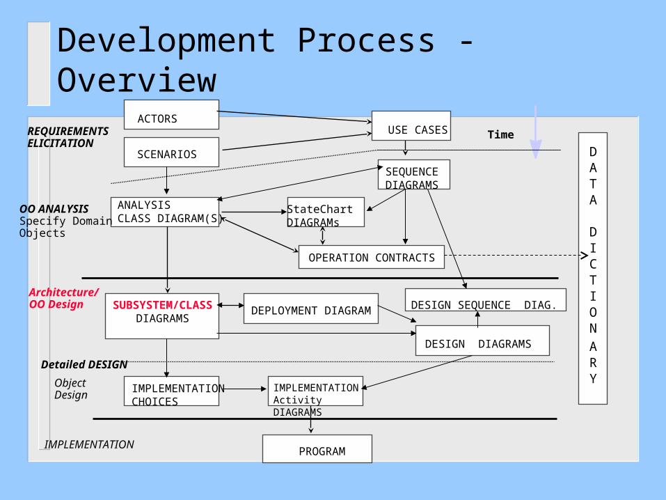
Development Process - Overview
PROGRAM
ACTORS
OO ANALYSISSpecify Domain Objects
Detailed DESIGN
IMPLEMENTATION
DATA
DICTION
ARY
TimeUSE CASES
ANALYSISCLASS DIAGRAM(S)
IMPLEMENTATIONActivity DIAGRAMS
SEQUENCEDIAGRAMS
OPERATION CONTRACTS
StateChart DIAGRAMs
DEPLOYMENT DIAGRAMSUBSYSTEM/CLASSDIAGRAMS
Architecture/OO Design
ObjectDesign
SCENARIOS
REQUIREMENTSELICITATION
DESIGN DIAGRAMS
IMPLEMENTATIONCHOICES
DESIGN SEQUENCE DIAG.

The Requirements, Analysis, and Design Models
Static Analysis Dynamic Analysis
Functional/ NonfunctionalRequirements
Use Case Diagrams/System Sequence Diagrams(the system level)
- Analysis Class Diagrams- StateChart Diagrams/Refined Sequence Diagrams (The domain object level)
Requirements ElicitationProcess
The AnalysisProcess
Static Design, Dynamic Design
The DesignProcess
• Design Class Diagrams,• StateChart Diagrams•Design Sequence/Collaboration Diagrams
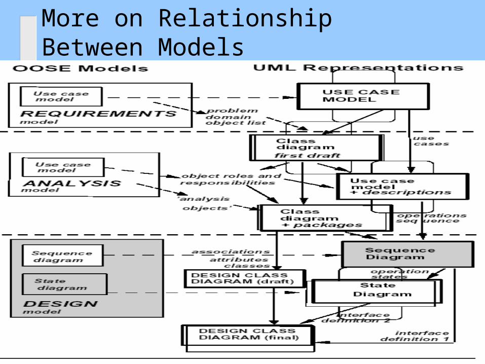
More on Relationship Between Models

More on Relationship Between Models
Example: A Digital Sound Recorder (DSR)From Requirements-to-Analysis-to-Design
The main function of the DSR is to record and playback speech.
The messages are recorded using a built-in microphone and they are stored in a digital memory.
The DSR contains an alarm clock with a calendar. The user can set a daily alarm. The alarm beeps until the user presses a key, or after 60 seconds.

Digital Sound Recorder: Showing the ProcessFrom Requirements-to-Analysis-to-Design

Digital Sound Recorder: Analysis Class Diagram (Object-Oriented Analysis, defining the domain objects)
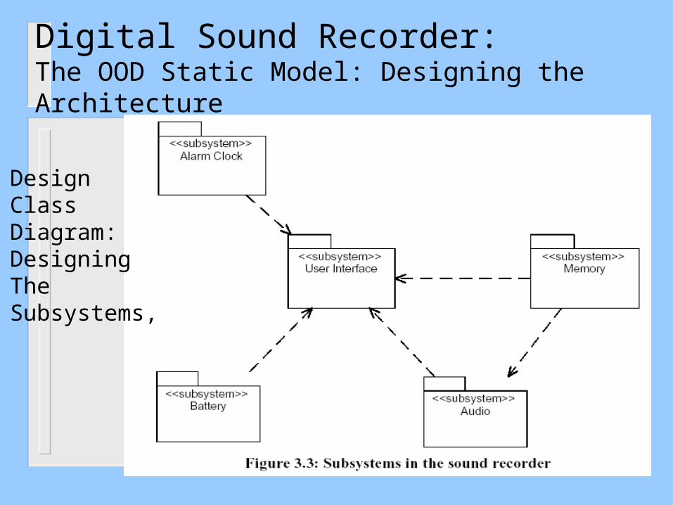
Digital Sound Recorder:The OOD Static Model: Designing the Architecture
DesignClass Diagram:DesigningThe Subsystems,
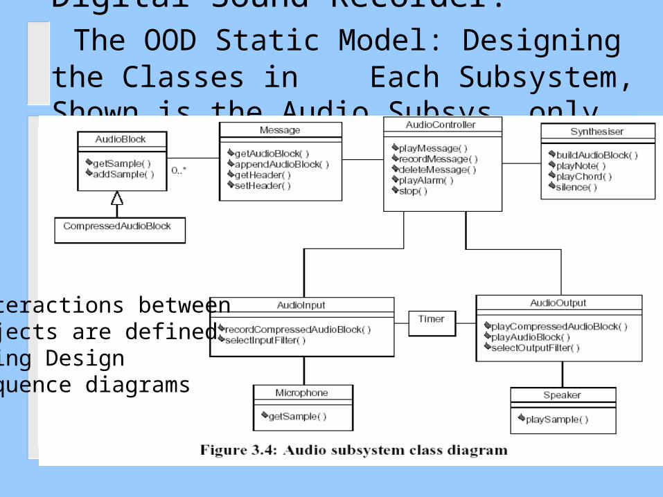
Digital Sound Recorder: The OOD Static Model: Designing the Classes in Each Subsystem, Shown is the Audio Subsys. only
Interactions betweenObjects are defined Using Design Sequence diagrams
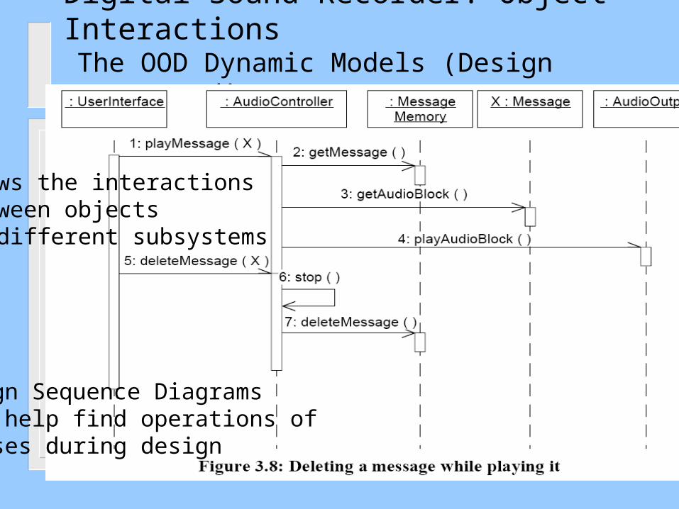
Digital Sound Recorder: Object Interactions The OOD Dynamic Models (Design Sequence diagrams)
Design Sequence Diagrams can help find operations of classes during design
shows the interactions between objects in different subsystems

Digital Sound Recorder: Object Interactions The OOD Dynamic model (Design Collaboration diag.)
Interactions are shown using a UML collaboration diagram. Timer interrupt update scenario
Notice anEventProxyClass is addedFor posting Events.Uses the ObserverAnd ProxyDesgin patterns
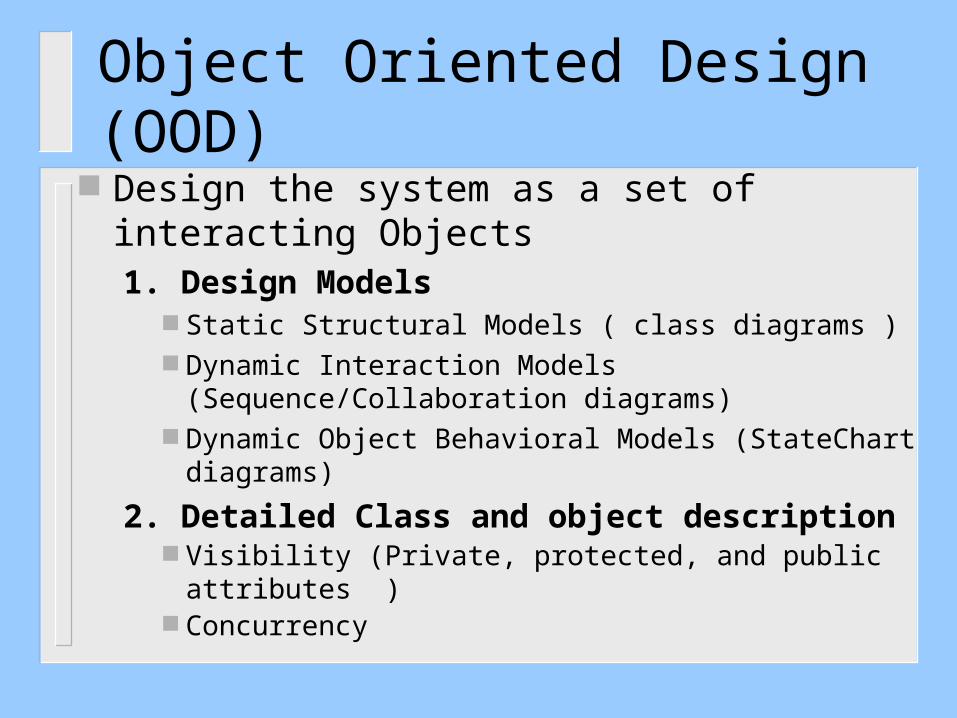
Object Oriented Design (OOD) Design the system as a set of interacting
Objects1. Design Models
Static Structural Models ( class diagrams ) Dynamic Interaction Models (Sequence/Collaboration
diagrams) Dynamic Object Behavioral Models (StateChart
diagrams)
2. Detailed Class and object description Visibility (Private, protected, and public attributes ) Concurrency
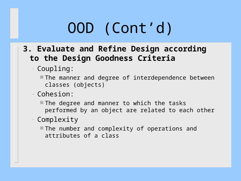
3. Evaluate and Refine Design according to the Design Goodness Criteria – Coupling:
The manner and degree of interdependence between classes (objects)
– Cohesion: The degree and manner to which the tasks performed by an
object are related to each other
– Complexity The number and complexity of operations and attributes of a
class
OOD (Cont’d)
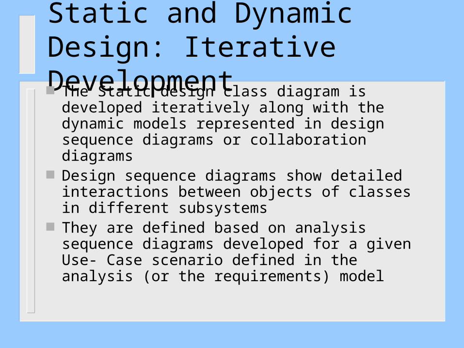
Static and Dynamic Design: Iterative Development The Static design class diagram is developed
iteratively along with the dynamic models represented in design sequence diagrams or collaboration diagrams
Design sequence diagrams show detailed interactions between objects of classes in different subsystems
They are defined based on analysis sequence diagrams developed for a given Use- Case scenario defined in the analysis (or the requirements) model

Static and Dynamic Design
The development of Design Class Diagrams is completed by defining the attributes and operations of classes to support the interactions represented in the dynamic model.
Operations of classes in the design class diagram are defined using the dynamic interactions in the dynamic model sequence diagrams
New classes might be needed in the design class diagram to support the interactions of objects in the sequence diagrams (e.g., Interface classes, proxy classes, scheduler classes etc.)

Class Operations Defined From Sequence Diagrams
The behavior of a class is represented by its operations Operations may be found by examining interaction
diagramsregistration
formregistration
manager
3: add course(joe, math 01)
RegistrationManager
addCourse(Student,Course)

OOD: How can we Identify Classes of Objects ?
Define classes such that each performs a specific function or task to maximize cohesion and minimize coupling, the following are typical examples of classes
Controllers – Subsystem controls a given aspect of the system
Coordinators/Schedulers – Coordinates several control classes
Data Collectors/Monitors – Collects data from external environment
Data analyzersProvides reports and/or displays
Servers– Provides service for client classes,
User/Device Interface– Collection of classes supporting needs of users or devices

OOD: How can we develop Class Diagrams?
The development of the class diagram can be done using consolidated collaboration diagrams
These diagrams are obtained from combining several collaboration diagrams developed from different scenarios

Example: Consolidated Collaboration Diagram of an Elevator Control System
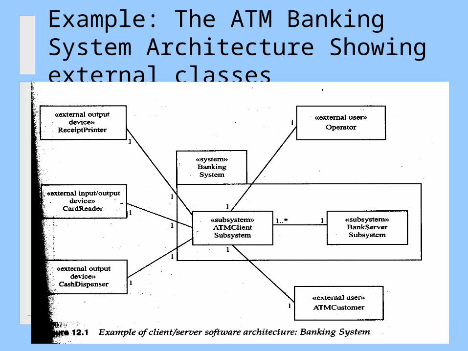
Example: The ATM Banking System Architecture Showing external classes
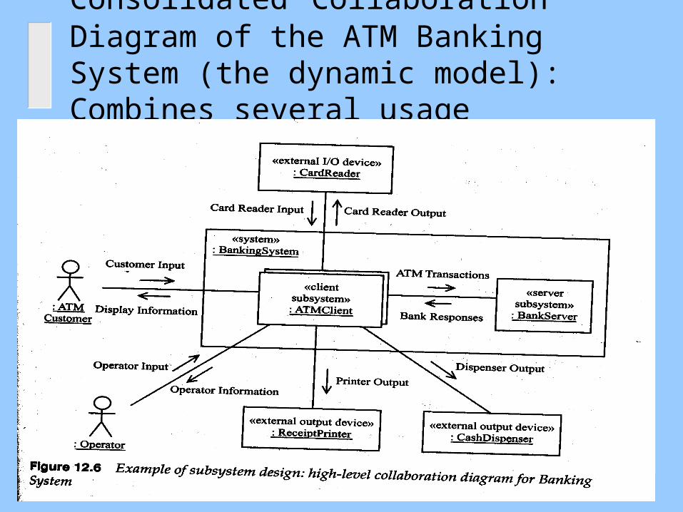
Consolidated Collaboration Diagram of the ATM Banking System (the dynamic model):Combines several usage scenarios

Consolidated Collaboration Diagram of the ATM Client Subsystem
The diagram can be easily used to develop the class diagram of the ATM Client Subsys.

OOD: How can we define the Behavior of Classes Example: State Chart of The ATMControl Class
StateCharts can be used to Refine the class diagram using the
State Pattern

Examples of Design Sequence Diagrams Notation

Examples of Design Sequence Diagrams Notation
Compound and Simple Iteration
* [for allInterfaces inContainer] Find( )
amMasterSI( )
setState( )
getInterfaceContainer()
* [for all Interfaces in Container] publishState() setOn( ) / setOff( )
{
:DiscreteFD:DiscreteFD
:Interface:Interface:InterfaceContainer:Subsystem :Resource

Examples of Design Sequence Diagrams Notation
Messages specified on interactions can be synchronous or asynchronous
updateStatus( )
Object1:C1 Object2:C2
calcRoute( )
route
Object1:C1 Object2:C2
Implicit Returns Explicit Return
Object3:C3
generateMessage( )
Synchronous (sequential call)

Examples of Design Sequence Diagrams Notation
Asynchronous (Concurrent Interactions)
asynchronous_Call ()
callBack ()
Object1:C1{active}
Object2:C2{active}

Examples of Design Sequence Diagrams Notation (UML 2)


