125 10 INJURY BIOMECHANICS RESEARCH Proceedings of the Thirty-First International Workshop Software to Predict Occupant Forces in Real World Crashes – Phase I Results S. A. Kebschull, J. W. Zellner, and L. V. Lombardo This paper has not been screened for accuracy nor refereed by any body of scientific peers and should not be referenced in the open literature. ABSTRACT Software is being developed under a US Department of Transportation Small Business Innovative Research Program that predicts occupant dynamics, kinematics, and contacts with vehicle interior surfaces in real world crashes. The software is being developed as a tool for medical, engineering, and crash investigators to better understand the biomechanics of crash injuries, simplify the reconstruction of injury mechanisms, and provide insight into potential injury mechanisms, injury prevention, and injury treatment. The software is intended to be a high capacity, economical, and easy to use bridge between accident databases and biomechanics and injury models. The software is based in part on a newly developed Graphics User Interface (GUI), an enhanced version of the US Air Force Articulated Total Body (ATB) multi-body crash simulation program, an extended version of the USAF Generator of Body Data (GEBOD) human modeling program, and DRI’s VisionForm 3D animation program used to visualize occupant and vehicle kinematics. In the Phase I proof-of-concept software, data for the vehicle, occupant, multi-stage 3D crash pulses, observed interior contacts and observed injuries can be downloaded from the CIREN accident database or by manual input. The Phase I software then provides for the automatic nominal positioning of the occupant and seat belt system in the vehicle, and subsequent simulation of the crash event. The user can then view animations of the resulting occupant and vehicle motions, and review a summary of the predicted occupant/vehicle contacts and contact forces. In Phase I, proof- of-concept software that provides basic functionality was successfully developed. It is anticipated that development to further extend its capabilities will result in a low-cost, commercially viable, easy-to-use software package that will aid crash investigators and safety researchers in further understanding the dynamics, kinematics, forces, and injuries associated with real world accidents.
Transcript
125
10
INJURY BIOMECHANICS RESEARCH Proceedings of the Thirty-First International Workshop
Software to Predict Occupant Forces in Real World Crashes – Phase I Results
S. A. Kebschull, J. W. Zellner, and L. V. Lombardo
This paper has not been screened for accuracy nor refereed by any body of scientific peers and should not be referenced in the open literature.
ABSTRACT
Software is being developed under a US Department of Transportation Small Business Innovative Research Program that predicts occupant dynamics, kinematics, and contacts with vehicle interior surfaces in real world crashes. The software is being developed as a tool for medical, engineering, and crash investigators to better understand the biomechanics of crash injuries, simplify the reconstruction of injury mechanisms, and provide insight into potential injury mechanisms, injury prevention, and injury treatment. The software is intended to be a high capacity, economical, and easy to use bridge between accident databases and biomechanics and injury models. The software is based in part on a newly developed Graphics User Interface (GUI), an enhanced version of the US Air Force Articulated Total Body (ATB) multi-body crash simulation program, an extended version of the USAF Generator of Body Data (GEBOD) human modeling program, and DRI’s VisionForm 3D animation program used to visualize occupant and vehicle kinematics. In the Phase I proof-of-concept software, data for the vehicle, occupant, multi-stage 3D crash pulses, observed interior contacts and observed injuries can be downloaded from the CIREN accident database or by manual input. The Phase I software then provides for the automatic nominal positioning of the occupant and seat belt system in the vehicle, and subsequent simulation of the crash event. The user can then view animations of the resulting occupant and vehicle motions, and review a summary of the predicted occupant/vehicle contacts and contact forces. In Phase I, proof-of-concept software that provides basic functionality was successfully developed. It is anticipated that development to further extend its capabilities will result in a low-cost, commercially viable, easy-to-use software package that will aid crash investigators and safety researchers in further understanding the dynamics, kinematics, forces, and injuries associated with real world accidents.
Injury Biomechanics Research
126
INTRODUCTION
his project comprises Phase I of a U.S. Department of Transportation Small Business Innovative Research program (solicitation number DTRS57-02-R-SBIR) to develop software
to predict occupant forces in real world crashes. The purpose of the Phase I effort was to assess the feasibility of developing such software. Phase II, which is contingent upon the results of the Phase I effort and available funding, would comprise the main software development effort.
The software is being developed as a tool for medical, engineering, and crash investigators to better understand the biomechanics of crash injuries, to simplify the reconstruction of injury mechanisms, and to provide insight into potential injury mechanisms, injury prevention, and injury treatment. The software is intended to be a high capacity, economical, and easy to use “bridge” between accident databases and biomechanics and injury models. The software is based on various models and functional elements, including:
- a newly developed Graphics User Interface (GUI), - an enhanced version of the US Air Force Articulated Total Body (ATB) multi-
body crash simulation program (“DRI/ATB1 User’s Manual Ver. 2.08,” 2003), - an extended version of the USAF GEBOD (Generator of Body Data) human
modeling program (Baughman, 1983), and - DRI’s VisionForm 3D animation program (“VisionForm User’s Guide,” 1992)
used to visualize occupant and vehicle kinematics. In the Phase I proof-of-concept software, coded real world accident data for the vehicle, occupant, multi-stage 3D crash pulses, observed interior contacts and observed injuries can be downloaded from the CIREN accident database or can be input manually for any other accident. The Phase I software then provides for the automatic “normal” positioning of the occupant and seat belt system in the vehicle, and subsequent running of the multi-body simulation of the crash event. The user can then view animations of the resulting occupant and vehicle motions, and review a summary of the predicted occupant/vehicle contacts and contact forces.
In Phase I, proof-of-concept software that provides basic functionality was successfully developed. It is anticipated that development to further extend its capabilities will result in a low-cost, commercially viable, easy-to-use software package that will aid crash investigators and safety researchers in further understanding the dynamics, kinematics, forces, and injuries associated with real world accidents.
In order to develop an easy-to-use tool that would not require the user to have extensive training and experience in modeling and running these types of Newtonian, multi-body simulations, it was determined that the software would contain the following features:
1) Be capable of importing extensive data from crash databases. 2) Contain alternative vehicle interior models representing various seating types. 3) Include in the vehicle interior model the main impacting surfaces and objects in
generic form. 4) Allow parameterized modification of the available vehicle interior models 5) Automatically generate statistically based occupant models as a function of
occupant age, height, weight, and gender. 6) Include in the occupant models the main skeletal articulations and skeletal and soft
tissue regions of interest for crash simulation.
T
Software to Predict Occupant Forces in Real World Crashes – Phase I Results
127
7) Allow various methods for defining the crash pulse, including importing data from Event Data Recorder (EDR) files or inputting Delta V values.
8) Allow automatic generation of contact surface intrusion motions, based on intrusion data from crash databases.
9) Automatically position the occupant in a “normal” posture on the vehicle seat, and automatically position the seat belt in a “normal” path across the lap and torso of the occupant.
10) Run crash simulations that produce animations of vehicle and occupant motions and summaries of contacts between occupant body parts and vehicle interior surfaces.
11) Calculate a figure-of-merit for each simulation relating the predicted occupant/vehicle contacts to the observed occupant/vehicle contacts reported in the crash databases.
12) Be comprised of public domain software or software developed by DRI, in order to minimize the cost basis of the software.
APPROACH
In order to meet the requirements and integrate the features described above, the following software components were selected to be developed as necessary and integrated into the software:
1) A GUI in order to simplify program usage and data input and to summarize
simulation results. 2) Enhanced version of GEBOD program to generate occupant models and simulation
input files. 3) Enhanced version of the ATB program to run the seating and crash simulations. 4) VisionForm 3D animation program to visualize the simulation results. The software was designed for the user to interact with it through the GUI, using mouse-
driven menu tabs and value entry boxes. The GUI uses a tabbed interface with nine tabs that function as follows:
1) “Crash” tab – User specifies the case ID number and loads the case information
from the database. 2) “Vehicle” tab – User can enter or modify the vehicle parameters that will be used
in the simulations. 3) “Occupant” tab – User can enter or modify the occupant parameters that will be
used in the program. 4) “Crash Event” tab – User enters the crash pulse data that will be used to drive the
vehicle motion in the crash simulations. 5) “Intrusion” tab – User can enter or modify the intrusion parameters that will be
used in the crash simulations. 6) “Injuries” tab – User can enter or modify the injury and contact source information
that will be compared with the crash simulation results. 7) “Occupant Positioning” tab – User can run the occupant positioning simulations in
order to calculate the seating position and fit the belt to the seated occupant, and in order to view the animations of each occupant positioning simulation.
8) “Crash Simulation” tab – User can run the crash simulations and view the animations of each simulation.
9) “Contact Summary” tab – User can compare the predicted contact information from the crash simulations with the observed contact information from the “Injuries” tab.
Injury Biomechanics Research
128
In a general sense, the first six tabs listed above are used sequentially for data input, tabs 7
and 8 are used to run the simulations, and tab 9 is used to evaluate the simulation results. At any point, the data on the earlier tabs can be modified and the simulation re-run. In addition, a list or matrix of runs can be input, run, and reviewed.
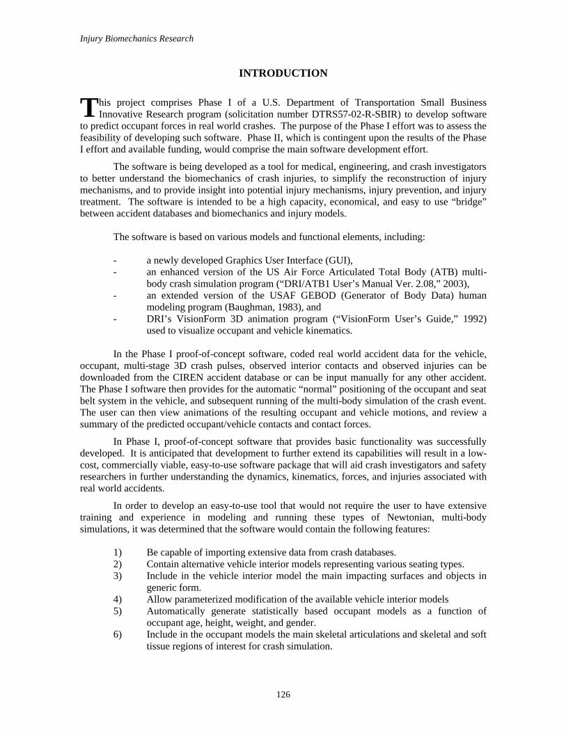
The “occupant positioning” simulation is a simulation that is run for two seconds with the vehicle in a stationary position. The occupant is placed in a nominal initial position above the seat and the seat belts are placed in a longitudinal-vertical plane located to the occupant’s right side as shown in Figure 1. During the simulation, the occupant is dropped into the seat and the belts are draped across the occupant’s lap and torso.
A key feature of the software is that multiple values can be entered for many of the simulation parameters, and the software will build a full matrix of input parameter combinations to be simulated. For example, in the input fields for weight and height, a user could enter three different occupant weights and three different occupant heights, separated by commas. The program will then generate a full matrix of the nine combinations of height and weight to be run in nine different simulation runs. In this way, parameter studies can be run to see the effects of varying one or more parameters. This can be useful to aid in determining possible values of unknown parameters. In the Phase I software, values for 7 different occupant and vehicle parameters can be varied in this way, and more parameters are planned in the future.
Note that whenever the user manually enters data into the DySIM program, those data are only used for the current series of simulations. The data are not saved back into the CIREN database.
In order to compare the contacts between the occupant body parts and vehicle interior surfaces predicted by the simulation with those contacts observed in the actual crash, the program calculates a figure-of-merit (“Score” or “Match”) for each simulation according to the equation shown below.
Software to Predict Occupant Forces in Real World Crashes – Phase I Results
129
Figure 1: Still images from example seating simulation
Injury Biomechanics Research
130
Figure 1: Still images from example seating simulation (cont’d)
Software to Predict Occupant Forces in Real World Crashes – Phase I Results
131
Note that the figure-of-merit is a number between 0 and 100, where 100 indicates that the
simulation correctly predicted each of the contacts observed in the actual crash, and a score of 0 indicates that the simulation did not predict any of the observed contacts. The score is weighted according to the confidence level assigned by the investigator to each contact and the injury AIS level associated with each contact. Observed contacts that are not predicted by the simulation and which have a high confidence level or high AIS level decrement the score more than those that have a low confidence level or low AIS level. In this way, the figure-of-merit emphasizes those contacts for which the investigator had higher confidence in the observation, or which had greater injury severity levels.
Since the purpose of the Phase I effort was to determine the technical feasibility of this approach, the software that was developed is applicable for only one crash type (frontal accident), one seating position (driver side), and one vehicle model (2000 Honda Accord). It is believed that, following Phase I, extending the software to include multiple crash types, seating positions, and vehicle models is relatively straightforward and does not represent new technology whose feasibility remains to be proven.
The “crash simulation” is run for the duration of the crash pulse specified by the user on the “Crash Event” tab. The vehicle motion is driven by the longitudinal, lateral, and yaw accelerations defined by the user using that tab. The final occupant and seat belt positions from the “occupant positioning” simulation are used as the initial positions for the “crash simulation” as shown in Figure 2.
not if 0 contact, observed the predicts simulation the if 1
squared AIS tcoefficien weighting severity injury
contact occupant ith with associated injury the of AIS observed
contacts occupant observed of number contact occupant observed of index
*100)(
1
1
=
=======
=
∑
∑
=
=
i
iAIS
i
CERTAINTY
i
contacts
contactsn
iiAISiCERTAINTY
contactsn
iiiAISiCERTAINTY
PREDICTEDCORRECTLY
q
AIS
P
CERTAINTY
ni
qp
PREDICTEDCORRECTLYqp
MATCHorSCORE
Injury Biomechanics Research
132
Figure 2: Still images from example crash simulation
Software to Predict Occupant Forces in Real World Crashes – Phase I Results
133
Figure 2: Still images from example crash simulation (cont’d)
Injury Biomechanics Research
134
RESULTS
Software
The completed software comprises four major components. The first is the Graphical User Interface (GUI), which is the main interface between the user and the software. The GUI was written in Microsoft Visual C# (Microsoft Developer Network Documentation, 2002) which is a part of the Visual Studio .NET development environment. This is a relatively new, object-oriented language that combines the ease of GUI development found in Visual Basic with the robust, object-oriented features of C++.
One of the reasons that this language was selected is that the .NET environment allows multi-language applications to be developed relatively easily. This is important since the other incorporated software components had been written previously in C and FORTRAN. Although these other components were not compiled in the .NET environment, .NET versions of these other compilers are available. Further development of this software would make use of the multi-language capabilities to further enhance, extend, make more robust and integrate the software.
Other reasons for using this language were the desire to use a modern, object-oriented language that could result in easily-maintainable code and to have a relatively easy to use GUI builder for more rapid application development.
In addition to functioning as the main interface between the user and the software, the GUI program computes and displays the figure-of-merit discussed previously.
The second software component, written in FORTRAN, is an enhanced version of the GEBOD human model generator. This program was originally developed by the U.S. Air Force to produce occupant parameters for the ATB simulation program. The version used in the DySIM program has been enhanced by adding additional soft tissue contact surfaces for the occupant’s breasts and skeletal contact surfaces for the occupant’s clavicles, sternum, rib cages, two spinal segments, and pelvis. In addition, the chest model was refined to allow visco-elastic compression of the rib cage relative to the spine in accordance with the chest model developed by Lobdell (Lobdell, et al., 1973). The GEBOD program was also modified to output other portions of the ATB input files for the occupant positioning and crash simulations.
The third software component, also written in FORTRAN, is an enhanced version of the U.S. Air Force Articulated Total Body (ATB) multi-body crash simulation program. This program was originally developed by Calspan Corporation for the National Highway Traffic Safety Administration. At that time, it was known as the Crash Victim Simulation (CVS) program (Cheng, et al., 1998).
More recently, the program has been maintained and enhanced by the U.S. Air Force which has used it to study, among other topics, the safety aspects of pilot ejection from aircraft. The enhancements that have been made include the addition of various joint models, increased dimensions, addition of rotational spring-dampers, addition of general feedback controllers, and various bug fixes (“DRI/ATB1 User’s Manual Ver. 2.08,” 2003). In addition, the segment description and motion time history output formats were modified by DRI to support the use of the VisionForm animation program.
The ATB program is formulated according to Newton’s laws of motion. At each time step, the program calculates all the external forces and torques acting on each body, including joint, contact, spring, and gravity forces. The resulting forces and torques are resolved and used to calculate linear and angular accelerations, which in turn are integrated into velocities and
Software to Predict Occupant Forces in Real World Crashes – Phase I Results
135
displacements using a vector exponential integrator. A variable time step is used in the integration to provide a combination of high accuracy and high computational efficiency.
The fourth software component is the DRI 3D animation program called VisionForm, written in C and based on the OpenGL graphics programming standard. This program was developed as a general-purpose tool for visualizing 3D time-dependant motions using smooth-shaded graphics. It includes capabilities for multiple simultaneous viewports, user selectable camera viewpoints, and attachment of cameras to objects.
VisionForm has been installed in this application so as to display only the actual geometric shapes that are used as contact surfaces in the mathematical simulations. In other words, additional graphical embellishments, which could lead to misinterpretation of the results, have not been added.
Various other utility programs have been developed in order to facilitate the communication between the software components. It is envisioned that in the future the software components and these utility programs would be integrated as modules into a single program. This would result in simpler, faster, more robust, and more easily maintainable software.
The recommended minimum hardware configuration for running the DySIM program is a 1.8 GHz Pentium 4, 256 MB RAM, 4 GB free disk space, 3D graphics card with 32 MB RAM, and a 1024 x 768 pixel display. With this hardware configuration, “occupant positioning” simulations require approximately 3 minutes to run, and a typical 200 ms “crash simulation” require approximately 2 minutes to run.
The program will run under Windows 2000 and Windows XP operating systems. Depending on configuration and settings, it may be possible to run the program under Windows 98, Windows ME, and Windows NT, but these operating systems are not recommended.
Simulation models
The DySIM simulation models comprise generic models of the vehicle interior, the occupant, the seat belt, and the airbag. These can be specialized by the user in order to incorporate the characteristics of specific vehicles, occupants, and crash pulses.
Further details of the technical assumptions on which the vehicle, occupant, and crash pulse models are based is given on the first tab of the DySIM software (i.e., the “Crash” tab).
Currently, the only selectable vehicle interior model that has been developed for this application is a 2000 Honda Accord sedan, which represents a high sales volume mid size car in the US fleet. In the future, other vehicle models and interior types are planned to be added. The vehicle interior model consists of 31 contact surfaces for the seat, steering wheel, foot pedals, center console, door frame, windshield, floor, roof, and A and B pillars. Currently, the model does not contain doors, and only the driver’s side is modeled.
The occupant model consists of 30 contact surfaces and 18 bodies. These contact surfaces include ellipsoids to represent soft tissues of the occupant’s breasts and skeletal contact surfaces for the occupant’s clavicles, sternum, rib cages, two spinal segments, and pelvis. Spring-damper systems have been added to the chest and abdomen models to simulate compression of these body regions.
The seat belts have been modeled as systems of connected plates, to the ends of which are attached the standard ATB rope belt model. This hybrid model was used instead of the typical ATB rope belt model, in order to overcome contact limitations of the rope model. Contact was defined between the plates and the dummy surfaces, and each plate’s motions are a result of the
Injury Biomechanics Research
136
contact normal forces, contact friction forces, the adjacent plate's spring and damping forces, and gravity. The plates have stretch, bending and twisting degrees-of-freedom relative to one another.
In the Phase I software, the airbag has been modeled using the standard ATB control volume airbag. This consists of an ellipsoidal airbag with a fixed shape whose size changes as the airbag fills with gas. The pressure in the airbag is calculated according to a defined mass flow rate and temperature time histories using the ideal gas law. Forces are applied to the dummy surfaces based on the airbag pressure, area of contact and frictional forces.
Program operation
When the program is run, the main, tabbed interface shown in Figure 3 is displayed. The following section describes the function of each of the tabs.
When the program loads, it displays the DySIM graphical user interface (Fig. 3). The user begins by entering a case number, and clicking on the “Import CIREN Case” button. If the case is found in the database, the information is loaded into the program. Note that the database included with the Phase I DySIM demo is only an extract of approximately 400 cases from the main CIREN database. Also note that the other “Import” buttons are not currently functional, but represent the plan to implement more import functionality in possible future versions of the program.
Figure 3: DySIM graphical user interface
Software to Predict Occupant Forces in Real World Crashes – Phase I Results
137
After the “Crash” tab, the user can click on the “Vehicle” tab. The vehicle information
displayed here is the information that was imported from the CIREN database. The user can select a vehicle for the simulation that is similar to the case vehicle. However, in this proof-of-concept version of the program, only one vehicle, a 2000 Honda Accord, is available. Future versions are planned to include a library of vehicle models. The user can then click on “Import Vehicle Parameters” to display the selected vehicle model.
After the “Vehicle” tab, the user can click on the “Occupant” tab. The case occupant’s anthropometric parameters, seat position, and restraint information loaded from the CIREN database will be displayed. The user can enter multiple values for the parameters to build a matrix of simulations to be run. When the user clicks on “Generate Occupant Models”, the program will generate a matrix of simulation configurations for all combinations of the input parameters to be run. The user can display any of the resulting occupant models by selecting the occupant in the table and clicking on “View Selected Occupant”.
After the “Occupant” tab, the user can click on the “Crash Event” tab. To model the crash pulse, the user selects a number of stages to input for a crash pulse. For example, an impact followed by skidding to a stop might be modeled as two stages. Then, for each of the three degrees-of-freedom (longitudinal, lateral, and yaw), the user clicks on the respective “Edit” button to define the motion for the stages. Note that each degree-of-freedom must have some data entered in it, but also that if the user specifies different durations for each of the three degrees-of-freedom, the program will pad the shorter two time histories with zero accelerations to make them equal in length to the longest duration time history defined by the user.
The user can also click on the “Load EDR” button. This button will bring up a popup window where the user can browse to and select an EDR data file to import. After selecting the file, the EDR data is imported and will be available for the user to apply to a crash event stage.
After defining the crash pulses for each of the three degrees-of-freedom, the user can click on the “Animate Vehicle Motion” button. This will run the VisionForm program in a popup window to display a top view of the vehicle motion. This is useful to verify the crash pulse information entered by the user.
The user can also select “Displacement”, “Velocity”, or “Acceleration” from the “Display” dropdown menu to see the associated time histories for each of the degrees-of-freedom.
When the user clicks on one of the “Edit” buttons on the “Crash Event” tab, a popup window appears. Here, the user begins building the crash pulse for a degree-of-freedom by entering “Initial Displacement” and “Initial Velocity. Then the user selects a “Stage” to be edited, and then chooses one of the four methods to build the motion time histories for that stage. If the user chooses to use the EDR data for that stage, he only needs to click on “Apply”. Alternatively, the user can enter the “Delta V” and “Delta t” parameters and click on “Apply”, enter “Peak Acceleration” and “Time Duration” and click on “Apply”, or enter “Acceleration” and “Final Velocity” and click on “Apply”. After the user has defined each of the stages, he can click on “Save Changes and Return” to go back to the “Crash Event” tab.
After the “Crash Event” tab, the user can click on the “Intrusion” tab. Intrusion modeling has not been implemented in Phase I, and is currently being considered for possible Phase II development. Clicking on “Update Figures” would show the interior contact surfaces in the intruded state.
Injury Biomechanics Research
138
After the “Intrusion” tab, the user can click on the “Injuries” tab. Here, the injury information loaded from the CIREN database is displayed, including the injury source and injury source confidence level. The user can edit or add data as desired.
After the “Injuries” tab, the user can click on the “Occupant Positioning” tab. The list of simulations to be run is shown in the table, and the user can click on “Run Occupant Positioning Simulation” to run them. When they have completed running, as indicated in the “Status” field, the user can select a simulation from the table and click on “Play”. This will run the VisionForm program to display an animation of the selected seating simulation (Fig. 1).
After the “Occupant Positioning” tab, the user can click on the “Crash Simulation” tab. The list of simulations to be run is shown in the table, and the user can click on “Run Crash Simulations” to run them. When they have completed running, as indicated in the “Status” field, the user can select a simulation from the table and click on “Play”. This will run the VisionForm program to display an animation of the selected crash simulation (Fig. 2).
After the “Crash Simulation” tab, the user can click on the “Contact Summary” tab. Here the user can compare the observed contacts imported from the CIREN database with the simulated contacts. One table shows the list of simulations that were run, and the figure-of-merit score for each of the runs.
In another table, the columns representing the occupant body regions, and the rows representing the vehicle contact surfaces are displayed. Each of the boxes of the table is blank if no contact between the corresponding body region and vehicle contact surface was observed in the actual accident or predicted by the simulation. The box is gray if the contact was observed in the actual accident and has an asterisk in it if contact was predicted by the simulation. In other words, each gray box should have an asterisk in it if the simulation correctly predicted all of the observed contacts and received a score of 100.0.
If the user selects any of the boxes in the contact table, the corresponding contact force will be displayed in the “Contact force predicted by simulation” field. If the user changes the “Contact force reporting threshold” field, the program will recalculate whether the simulation contact forces exceed this value for each of the contacts, and it will place asterisks in the appropriate cells and recalculate the figure-of-merit score. Note that the “URGENCY v. 1.0” score is not currently being calculated, but may be added in a possible Phase II development effort.
CONCLUSIONS
The main purpose of this Phase I effort was to determine the technical feasibility of developing high capacity, economical, easy to use software that would allow crash investigators, such as those associated with NHTSA’s CIREN program, to more easily and consistently calculate crash forces from crash reconstructions and observed injuries. The software developed in Phase I meets these objectives for an example crash type, seating position, and vehicle model. User comments collected at two CIREN team workshops and two NHTSA briefings subsequently have indicated strong interest for the software and understanding of its technical features and assumptions. Most potential users have indicated that run times and ease-of-use are acceptable for typical applications. Although many opportunities remain for expanding the conditions for which the software is applicable and for developing additional features, it is clear from the capabilities themselves and from user feedback that development of the software into a final, commercial quality product is technically feasible.
The initial development of the software has focused on applications related to accident reconstruction by crash investigators for CIREN and for other similar accident databases. However, many other potential applications exist. The software could also be used to gain further
Software to Predict Occupant Forces in Real World Crashes – Phase I Results
139
insight into occupant kinematics, potential injury mechanisms, contributing factors, preventions, and treatments.
Another use could be in the development of biomechanics models such as NHTSA's SIMon. In this scenario, researchers could run DySIM simulations for a sample of accidents from an accident database to predict the gross occupant motions and forces that occurred in these accidents, and then use this information to further develop finite element models and injury criteria that explain the injuries observed in these accidents.
Another application could be for researchers to investigate the risks and benefits of new or existing vehicle features. In this scenario, researchers could run DySIM simulations for a sample of accidents from an accident database using a baseline vehicle model and a modified vehicle. In this way, the effects of the modification could be evaluated across samples of occupants, collision types, and speeds seen in real world accidents.
Based on the software developed in Phase I, and considered for Phase II, it is believed that further development of the software to meet the needs of these other applications is also technically feasible.
FUTURE DEVELOPMENT
The following list includes many of the features and functionalities being considered for inclusion in possible Phase II development efforts:
– Capability to import cases from the NASS database – Capability to import parameters from full-scale test data or other databases – Capability to model children – Capability to model infants – Capability to model child seat – Capability to model occupants as a function of seated height – Capability to model crash dummies – Calibration of models with ISO TR 9790 biofidelity requirements – Addition of energy absorbing steering column to vehicle model – Capability to model adjustable steering column – Capability to model seat belt pretensioners – Capability to model seat belt force limiters – Capability to model front passenger – Capability to model rear seat passengers – Capability to model multiple passengers – Adding four other specific vehicle models (e.g. minivan, SUV, pickup truck, large
sedan) – Capability to model any vehicle based on SAE J1100 parameters – Adding front passenger airbag model – Adding side thorax airbag – Adding side curtain airbag – Adding multi-stage airbag – Capability to include finite element airbag models – Capability to select between finite element and simple control volume airbag
models – Application of motion to intrusion surfaces during a selected stage of the crash
pulse
Injury Biomechanics Research
140
– Capability to model six degree-of-freedom motion (frontal, side, vertical, yaw, pitch, and roll)
– Capability to model rollovers – Capability to edit imported EDR data – Capability to model crash pulse by importing WinSmash results – Capability to model crash pulses using other pulse shapes (e.g. to model late
deployment or pole impact crash pulse shapes) – Capability to model crash pulses by importing time history data (e.g. from crash
tests) – Capability to predict simulated AIS levels for head, neck, chest, abdomen, femur,
knee, and tibia – Capability to predict injury assessment variables (e.g. HIC) – Capability to link to finite element human models (e.g. SIMon) – Capability to predict injuries based on age, gender, and habitus – Capability to adjust initial position of limbs and torso to simulate specific or
abnormal seating postures – Capability to adjust seat belt path to simulate specific belt paths or improper belt
usage – Capability to simulate vehicle motions resulting from impact (exterior simulation) – Adding additional vehicle parameters to sensitivity analysis matrix – Adding parameters for crash event to sensitivity analysis matrix – Adding parameters for intrusion to sensitivity analysis matrix – Prediction of occupant contact penetration, deflection, and rates – Capability to predict URGENCY 1.0 score – Capability to display color-coded maximum loads on occupants (e.g. from contact
with belt) – Capability to report contact stress – Capability to display peak seat belt loop loads – Capability to display sum of belt plate forces on each occupant body part – Variable animation “play” speed – Animation zoom – Animation pan – Animation view angle – Menu of additional preset camera views – Attachment of camera view to vehicle – Option to capture still image and animation files for each view – Inset animation windows in GUI screens – Option to animate full-screen – Capability to export contact force time histories – Capability to select “contact force reporting thresholds” separately for each contact – Validation/refinement of basic occupant GEBOD model
If it is decided to pursue Phase II development, the features to be added and changes to be made will be selected based on the priority of each feature or change, and the level of effort required to implement it.
Software to Predict Occupant Forces in Real World Crashes – Phase I Results
141
REFERENCES
BAUGHMAN, D. L. (July 1983). “Development of an Interactive Computer Program to Produce Body Description Data,” AFAMRL-TR-83-058, Air Force Aerospace Medical Research Laboratory.
CHENG, H., RIZER, A. L., and OBERGEFELL, L. A. (February 1998). “Articulated Total Body Model Version V User’s Manual,” AFRL-HE-WP-TR-1998-0015, United States Air Force Research Laboratory, Biodynamics and Protection Division Human Effectiveness Directorate Air Force Research Laboratory.
“DRI/ATB1 User’s Manual Ver. 2.08,” Dynamic Research, Inc., August 2003.
LOBDELL, T. E., KROELL, C. K., SCHNEIDER, D. C., HERING, W. E., and NAHUM, A. M. (1973). “Impact Response of the Human Thorax,” Human Impact Response Measurement and Simulation, W. F. King, H. J. Mertz, eds., Plenum Press, London, pp. 201-245.
Microsoft Developer Network Documentation (2002). Visual Studio .NET CD-ROM.
National Health and Nutrition Examination Survey, III 1988-94, U.S. Department of Health and Human Services Centers for Disease Control and Prevention, National Center for Health Statistics, PB97-502959, NCHS CD-ROM Series 11, No. 1, July 1997.
PAPER: Software to Predict Occupant Forces in Real World Crashes - Phase I
Results PRESENTER: John Zellner and Scott Kebschull, Dynamic Research, Inc.
QUESTION: [unidentified] When we've looked at some injury predictions from, say, sledge tests versus real-world
injuries, there seems to be a large difference based on some real-world--Real-world's a relative term, but field data, let's call it. There's seems to be large discrepancies, particularly in frontal crashes due to bias, due to--say--muscle tensing where you've got roughly 2/3 of at least drivers taking some base of action or braking or bracing in some way, and I didn't see that listed as one of the possibilities. And yet, bracing, in effect, can actually dominate the response. Is that something you've considered?
ANSWER: We thought about that. Actually, no one suggested it for this particular software tool; but in some of our other simulation tools, we do get into that area of neuromuscular response and tensing. No one suggested it for this particular tool, but I think it's a very interesting and important topic.
QUESTION: Madana Golpock, Delphi Corporation I have just one comment and probably a suggestion. In the panel--In the Phase I that you
showed us, where you have occupant positioning--and one of the critical things, based on my experience of working in this area, is to be able to have a good knowledge of equilibrium. When you drop the occupant in the seated position, you should at least have a way of looking at the panel that says that you have the correct force-deflection for your seat cushion or seat back or things like that so that at least the equilibrium weight of the occupant has to be in body length. Otherwise, what happens is it will generate a lot of darts and in the joints and other areas that you may not be able to see which may affect your kinematics or your contact positions you cannot derive. So, you have to have a panel at least be able to show that the total contact force of the occupant in your drop is in the ballpark of the occupant weight, for example.
A: So, what we've done in this particular model: We've measured and modeled the various seat stiffness and so on. So in our occupant seating position, at the end of that, we have checked that when we run our crash simulations, all of the accelerations--both linear and angular--on the dummy are very close to zero. So, we've checked that independently for a number of examples, but we don't rigorously check it for every--It's not a part of the automated code here that does.
Q: The reason is when you are going through the database of putting multiple occupants of different sizes and all of that, you still want to make sure that at least user has a way to work with that, if that automated way does not necessarily work.
A: Right. Yeah.
Q: In specific situations.
A: That was one of the things that we listed, and I agree. That is an important point is the, giving the user the ability to change that position because there are even other reasons why the users would need to change that position. For example, if the seatbelt were worn improperly, you'd
Software to Predict Occupant Forces in Real World Crashes – Phase I Results
143
want to be able to simulate the seatbelt being worn under the arm or the occupant in a leaned over position adjusting the radio or these other positions, as well.
Q: And, the second one is I'm assuming you'd want to extend the external environment modeling to include things like falling and other things that they can model because occupant contact may not necessarily always be equal.
A: Yeah, that's something we've talked about. We have to kind of have a balance between ease of use and the robustness of the model. And, one of the goals of this was to make it easy to use for non-engineers, for the accident researchers, but that would be an excellent thing to add as an option that maybe people who are more sophisticated--The people in this room, I think, are engineers who would be able to use that sort of thing. That would be a good point.
QUESTION: Joseph Pellettiere, Research Laboratories I just want to make a quick comment or a follow-up to Madana's question here. You may not
really want to use that one G set of settling for studying the initial position because 1) you can't really guarantee equilibrium. But, the other issue is: Once you start bringing in things like seatbelts and other contacts, those are actually going to affect your initial position. The other effect is because you're allowing him to settle, you kind of tend to get a position that slumps a little bit, so you're kind of slumping in the neck; there's slumping in that lower torso, as well--as well as allowing his arms just to kind of sit there and hang and freely flow. So, you can't really guarantee what initial position you have. Also, but there are some algorithms developed--There's one by John Flek--which actually automatically positions the occupant for you. You just give it your base initial position and it goes through, and in a very short time will iterate initial position for you as opposed to the way you're doing it now. Your initial position simulation time is, in order of magnitude, greater than your actual simulation time, so that'll greatly speed up this entire process when you have so many simulations at one iterate.
A: Right. That is a good point. We've used--In the past, we've used that equilibrium calculation module of AT--portion of ATB, and we've gotten kind of mixed results with it. We've had some problems getting it to give us good results in all, in all conditions, which is why we went to this approach. One of the--A thing I'd like to mention on the equilibrium thing: I agree with most of the points you made there. One of the things that we did with this model is we took 15 human subjects and seat them--asked them to sit in the vehicle in their most comfortable position, keeping their hands at 10 and 2 and buckling up and so forth. And then, we compared that with the seating simulation results here, looking at the position of the head, the position of the shoulders and so--hips and so on. We ended up getting a very good match using that approach. So, that's kind of the reason we went with that approach.
Q: Right. And, one other reason you might want to look at it for--I'm assuming the contact properties you're using now, you're just using the regular linear elastic force-deflection functions.
A: Well, they're actually non-linear.
Q: Well, from the non-linear, but they're still--they're fully elastic force-deflection functions, correct?
A: They're elastic for the seating simulation.
Q: Right.
A: And then, we switch them over to energy-absorbing force-deflection functions in the crash simulation.
Injury Biomechanics Research
144
Q: And some of the newer versions of ATB's--I'm not sure if you got that newest version yet. They actually have a version now that has the visco-elastic models built within it, built specifically for modeling seating applications. And in those situations there, it then becomes very important to actually have it just actually seated where you want; because if you, you know, get the settling effect in there, it'd be really hard for--It'll actually be a lot harder for you to iterate through a convergent solution because you're now modeling the visco-elastic effects.


![The influence of crash pulse shape on seat-occupant response · sustaining whiplash injury has been found to occur in rear-end crashes [1,2]. A common cause of whiplash is the formation](https://static.documents.pub/doc/80x56/5fa629dba4a7cd3fa805032a/the-influence-of-crash-pulse-shape-on-seat-occupant-response-sustaining-whiplash.jpg)


