1 CSM_G3PA_DS_E_2_2 Solid State Relays G3PA Extremely Thin Relays Integrated with Heat Sinks • Downsizing achieved through optimum design of heat sink. • Mounting possible via screws or via DIN track. • Close mounting possible for linking terminals. (Except for G3PA- 260B-VD and G3PA-450B-VD-2.) • Applicable with 3-phase loads. • Replaceable power element cartridges. • Comply with VDE 0160 (finger protection), with a dielectric strength of 4,000 V between input and load. • Certified by UL, CSA, and VDE (reinforced insulation). Refer to Safety Precautions for All Solid State Relays. Model Number Structure ■ Model Number Legend 1. Basic Model Name G3PA:Solid State Relay 2. Rated Load Power Supply Voltage 2: 200 VAC 4: 400 VAC 3. Rated Load Current 10: 10 A 20: 20 A 30: 30 A 40: 40 A 50: 50 A 60: 60 A 4. Terminal Type B: Screw terminals 5. Zero Cross Function Blank: Equipped with zero cross function L: Not equipped with zero cross function 6. Certification VD: Certified by UL, CSA, and VDE 7. Special Specifications Blank: Standard models 2: 480-V models 1 2345 6 7 G3PA-@@@@-@-@
Transcript
1
CSM_G3PA_DS_E_2_2
Solid State Relays
G3PAExtremely Thin Relays Integrated with Heat Sinks
• Downsizing achieved through optimum design of heat sink.
• Mounting possible via screws or via DIN track.
• Close mounting possible for linking terminals. (Except for G3PA-260B-VD and G3PA-450B-VD-2.)
• Applicable with 3-phase loads.
• Replaceable power element cartridges.• Comply with VDE 0160 (finger protection), with a dielectric
strength of 4,000 V between input and load.
• Certified by UL, CSA, and VDE (reinforced insulation).
Refer to Safety Precautions for All Solid State Relays.
Model Number Structure
Model Number Legend
1. Basic Model NameG3PA: Solid State Relay
2. Rated Load Power Supply Voltage2: 200 VAC4: 400 VAC
5. Zero Cross FunctionBlank: Equipped with zero cross functionL: Not equipped with zero cross function
6. CertificationVD: Certified by UL, CSA, and VDE
7. Special SpecificationsBlank: Standard models2: 480-V models
1 2 3 4 5 6 7G3PA-@@@@-@-@
G3PA
2
Ordering Information
List of Models
Note: When ordering, specify the rated input voltage.
Replacement Parts
Other Units (Order Separately)Units that Enable 2-line Switching of 3-phase Power
Note: Refer to List of Certified Models for a list of products that comply with safety standards.
Model Isolation Zero cross function Indicator Rated output load Rated input voltage
G3PA-210B-VD Phototriac coupler
Yes Yes 10 A at 24 to 240 VAC 5 to 24 VDC
G3PA-220B-VD 20 A at 24 to 240 VAC
G3PA-240B-VD 40 A at 24 to 240 VAC
G3PA-260B-VD 60 A at 24 to 240 VAC
G3PA-210BL-VD No 10 A at 24 to 240 VAC
G3PA-220BL-VD 20 A at 24 to 240 VAC
G3PA-240BL-VD 40 A at 24 to 240 VAC
G3PA-260BL-VD 60 A at 24 to 240 VAC
G3PA-210B-VD Yes 10 A at 24 to 240 VAC 24 VAC
G3PA-220B-VD 20 A at 24 to 240 VAC
G3PA-240B-VD 40 A at 24 to 240 VAC
G3PA-260B-VD 60 A at 24 to 240 VAC
G3PA-420B-VD 20 A at 180 to 400 VAC 12 to 24 VDC
G3PA-430B-VD 30 A at 180 to 400 VAC
G3PA-420B-VD-2 20 A at 200 to 480 VAC
G3PA-430B-VD-2 30 A at 200 to 480 VAC
G3PA-450B-VD-2 50 A at 200 to 480 VAC
Name Carry current Load voltage range Model Applicable SSR VDE certification
Power Device Cartridge
10 A 19 to 264 VAC G32A-A10-VD DC5-24 G3PA-210B-VD DC5-24 Yes
G32A-A10L-VD DC5-24 G3PA-210BL-VD DC5-24
G32A-A10-VD AC24 G3PA-210B-VD AC24
20 A G32A-A20-VD DC5-24 G3PA-220B-VD DC5-24
G32A-A20L-VD DC5-24 G3PA-220BL-VD DC5-24
G32A-A20-VD AC24 G3PA-220B-VD AC24
40 A G32A-A40-VD DC5-24 G3PA-240B-VD DC5-24
G32A-A40L-VD DC5-24 G3PA-240BL-VD DC5-24
G32A-A40-VD AC24 G3PA-240B-VD AC24
60 A G32A-A60-VD DC5-24 G3PA-260B-VD DC5-24
G32A-A60L-VD DC5-24 G3PA-260BL-VD DC5-24
G32A-A60-VD AC24 G3PA-260B-VD AC24
20 A 150 to 440 VAC G32A-A420-VD DC12-24 G3PA-420B-VD DC12-24
30 A G32A-A430-VD DC12-24 G3PA-430B-VD DC12-24
20 A 180 to 528 VAC G32A-A420-VD-2 DC12-24 G3PA-420B-VD-2 DC12-24
30 A G32A-A430-VD-2 DC12-24 G3PA-430B-VD-2 DC12-24
50 A G32A-A450-VD-2 DC12-24 G3PA-450B-VD-2 DC12-24
Name Current flow Model Applicable SSR
Short-circuit Unit 10 A G32A-D20 G3PA-210B-VD, G3PA-210BL-VD
20 A G3PA-220B-VD, G3PA-220BL-VDG3PA-420B-VD, G3PA-420B-VD-2
30 A G32A-D40 G3PA-430B-VD, G3PA-430B-VD-2
40 A G3PA-240B-VD, G3PA-240BL-VD
G3PA
3
Specifications
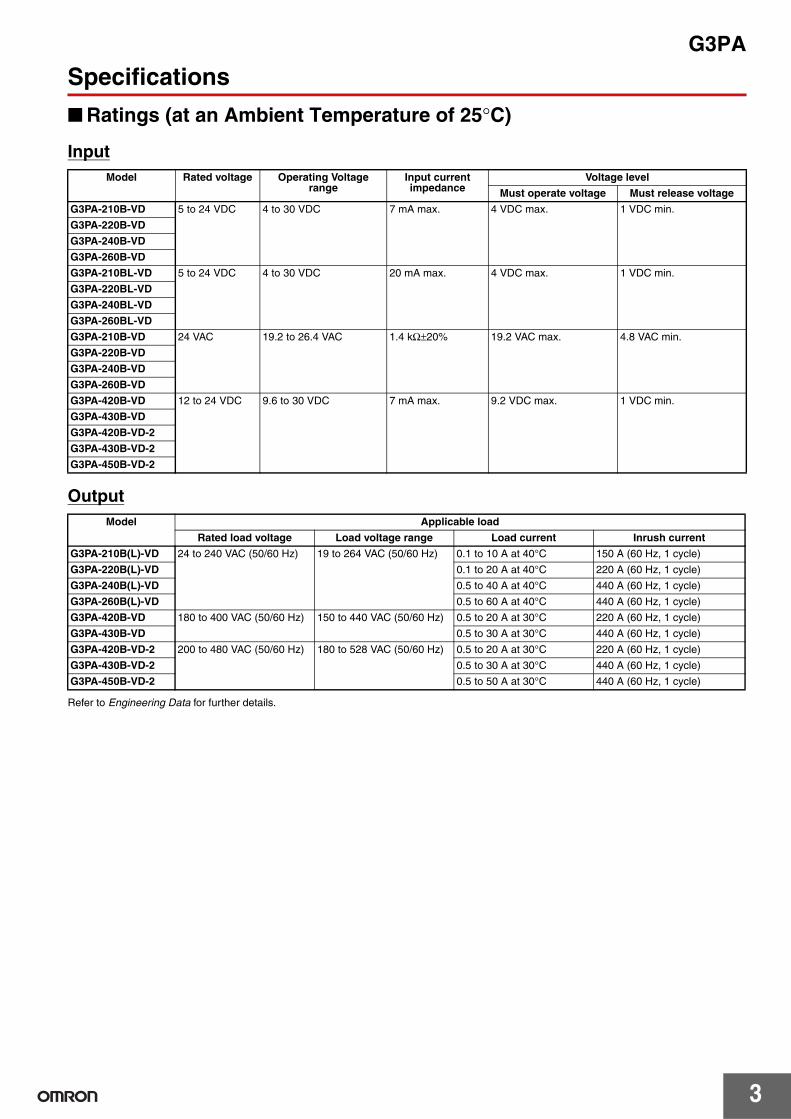
Ratings (at an Ambient Temperature of 25°C)
Input
Output
Refer to Engineering Data for further details.
Model Rated voltage Operating Voltage range
Input current impedance
Voltage level
Must operate voltage Must release voltage
G3PA-210B-VD 5 to 24 VDC 4 to 30 VDC 7 mA max. 4 VDC max. 1 VDC min.
G3PA-220B-VD
G3PA-240B-VD
G3PA-260B-VD
G3PA-210BL-VD 5 to 24 VDC 4 to 30 VDC 20 mA max. 4 VDC max. 1 VDC min.
G3PA-220BL-VD
G3PA-240BL-VD
G3PA-260BL-VD
G3PA-210B-VD 24 VAC 19.2 to 26.4 VAC 1.4 kΩ±20% 19.2 VAC max. 4.8 VAC min.
G3PA-220B-VD
G3PA-240B-VD
G3PA-260B-VD
G3PA-420B-VD 12 to 24 VDC 9.6 to 30 VDC 7 mA max. 9.2 VDC max. 1 VDC min.
G3PA-430B-VD
G3PA-420B-VD-2
G3PA-430B-VD-2
G3PA-450B-VD-2
Model Applicable load
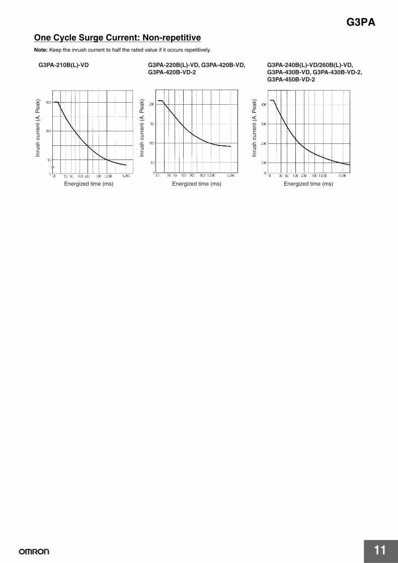
Rated load voltage Load voltage range Load current Inrush current
G3PA-210B(L)-VD 24 to 240 VAC (50/60 Hz) 19 to 264 VAC (50/60 Hz) 0.1 to 10 A at 40°C 150 A (60 Hz, 1 cycle)
G3PA-220B(L)-VD 0.1 to 20 A at 40°C 220 A (60 Hz, 1 cycle)
G3PA-240B(L)-VD 0.5 to 40 A at 40°C 440 A (60 Hz, 1 cycle)
G3PA-260B(L)-VD 0.5 to 60 A at 40°C 440 A (60 Hz, 1 cycle)
G3PA-420B-VD 180 to 400 VAC (50/60 Hz) 150 to 440 VAC (50/60 Hz) 0.5 to 20 A at 30°C 220 A (60 Hz, 1 cycle)
G3PA-430B-VD 0.5 to 30 A at 30°C 440 A (60 Hz, 1 cycle)
G3PA-420B-VD-2 200 to 480 VAC (50/60 Hz) 180 to 528 VAC (50/60 Hz) 0.5 to 20 A at 30°C 220 A (60 Hz, 1 cycle)
G3PA-430B-VD-2 0.5 to 30 A at 30°C 440 A (60 Hz, 1 cycle)
G3PA-450B-VD-2 0.5 to 50 A at 30°C 440 A (60 Hz, 1 cycle)
G3PA
4
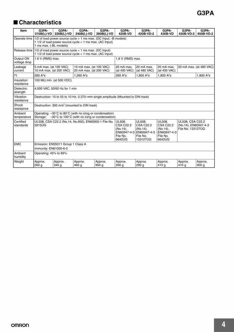
CharacteristicsItem G3PA-
210B(L)-VDG3PA-
220B(L)-VDG3PA-
240B(L)-VDG3PA-
260B(L)-VDG3PA-
420B-VDG3PA-
420B-VD-2G3PA-
430B-VDG3PA-
430B-VD-2G3PA-
450B-VD-2
Operate time 1/2 of load power source cycle + 1 ms max. (DC Input, -B models)1 1/2 of load power source cycle + 1 ms max. (AC Input)1 ms max. (-BL models)
Release time 1/2 of load power source cycle + 1 ms max. (DC Input)1 1/2 of load power source cycle + 1 ms max. (AC Input)
EMC Emission: EN55011 Group 1 Class AImmunity: EN61000-6-2
Ambient humidity
Operating: 45% to 85%
Weight Approx. 260 g
Approx. 340 g
Approx. 460 g
Approx. 900 g
Approx. 290 g
Approx. 290 g
Approx. 410 g
Approx. 410 g
Approx. 900 g
G3PA
5
Operation
Replacement Parts
G32A-A Power Device CartridgeThe G32A-A Power Device Cartridge (a Triac Unit) can be replaced with a new one. When the temperature indicator has changed from pink to red, the triac circuitry may have malfunctioned possibly by an excessive flow of current, in which case, dismount the damaged cartridge for replacement.
The damaged cartridge can be replaced with a new one without disconnecting the wires from the G3PA.
Improve the heat radiation efficiency of the G3PA before replacing the cartridge.
The G32A-A Power Device Cartridge can withstand an excessive current for a short period of time, such as may be caused accidentally by the short circuitry of the load, in which case the temperature indicator will not turn red.
Be sure to turn OFF the power supply when replacing the Cartridge. Supplying power with the Cartridge removed may result in malfunction.
To remove or replace the Power Device Cartridge for the G3PA-210B-VD, G3PA-220B-VD, or G3PA-420B-VD(-2), use the special tool provided with it for extraction. (No special tool is required for other models.)
The G3PA can be broadly divided into two series: Previous models and models with model numbers that end with "-VD." The Cartridge shown at the right cannot be mounted to models in the G3PA-@@@B-(-US) Series.
Appearance
Replacing Power Device CartridgesWhen replacing Power Device Cartridges, use the specified model. Using a Power Device Cartridge other than the specified one will result in faulty operation and destruction of the elements.
G32A-A10(L)-VD/G32A-A20(L)-VD/G32-A420-VD(-2)To remove or replace the Power Device Cartridge, use the special tool provided with it for extraction.
ExtractionFollow the procedures below to dismount the Power Device Cartridge from the G3PA.
1. Switch off the power.2. Remove the terminal cover.3. Hook the indented part of the cartridge with the tool and pull up
on the cartridge to remove it.
MountingFollow the procedures below to mount the Power Device Cartridge on the G3PA.
1. Apply silicone grease (provided with the G32A-A) to the entire surface of the heat sink.
2. Make sure that there is no dust or pieces of wire on the heat sink of the G32A-A or the G3PA.
3. Insert the cartridge into the opening of the G3PA so that the letters on the cartridge and those on the G3PA are in the same direction and side A and side B are even.
4. Attach the terminal cover.5. Switch on the power and check the G3PA to be sure it works
properly.
G32A-A40(L)-VD/G32A-A60(L)-VD/G32A-A430-VD(-2)/G32A-A450-VD-2The G32A Power Device Cartridge is mounted and secured with screws to the G3PA Unit. No special tool is required to remove the Cartridge.
ExtractionFollow the procedures below to dismount the G32A-A Power Device Cartridge from the G3PA.
1. Switch off the power.2. Remove the terminal cover.3. Loosen the two centered screws on the sides to dismount the
cartridge. The screws are connected to terminals 1 and 2.
4. Loosen the screws on both the corners.
5. Hold the indented part of both the corners to dismount the cartridge.
Mounting1. Apply silicone grease to the entire surface of the heat sink.
2. Make sure that there is no dust or pieces of wire on the heat sink of the G32A-A or the G3PA.
Remover
Hook here with Remover.
Apply silicone grease here.
Side A
Side B
Loosen
Loosen
Loosen
Loosen
Apply silicone grease here.
G3PA
7
3. Insert the cartridge into the opening of the G3PA so that side A and side B are even.
4. Tighten the screws on both the corners with a tightening torque of 0.59 to 0.78 N·m.
5. Tighten the screws on both the sides with a tightening torque of 0.59 to 0.78 N·m.
6. Attach the terminal cover.7. Switch on the power and check the G3PA to be sure it works
properly.
Linking Terminal Connection• Connecting with linking terminal for G3PA-210B(L)-VD, -220B(L)-
VD, -240B(L)-VD and G3PA-420B-VD(-2), G3PA-430B-VD(-2).• Connecting with linking terminal for G32A.
Side B
Side A
SSR1 SSR2 SSR1 SSR2
1. When SSRs are close mounted, loosen the M3.5 Sems screw and flip the linking terminal down.
2. Insert the linking terminal securely into the center of the screw and tighten the screw.
*
SSR G32A Unit SSR G32A Unit
* The cover will not fit if the terminal protrudes.
1. When SSR are close mounted, loosen the M3.5 Sems screw on the G32A and flip the linking terminal down.
2. Insert the linking terminal securely into the center of the screw and tighten the screw. Ensure that the linking terminal does not protrude.
Linking terminal
Linking terminal
Connect the terminal with power off.
G3PA-420B-VD
Refer to the instruction manual for the G32A-A Power Device Cartridge to replace the G3PA's triac part.
When the temperature indicator has turned from pink to red, the G32-A-A Power Device Cartridge may have malfunctioned, in which case the cartridge must be replaced with a new one.
Use the terminal cover to prevent accidents due to electric shock.
Linking terminal
Linking terminal
G3PA
8
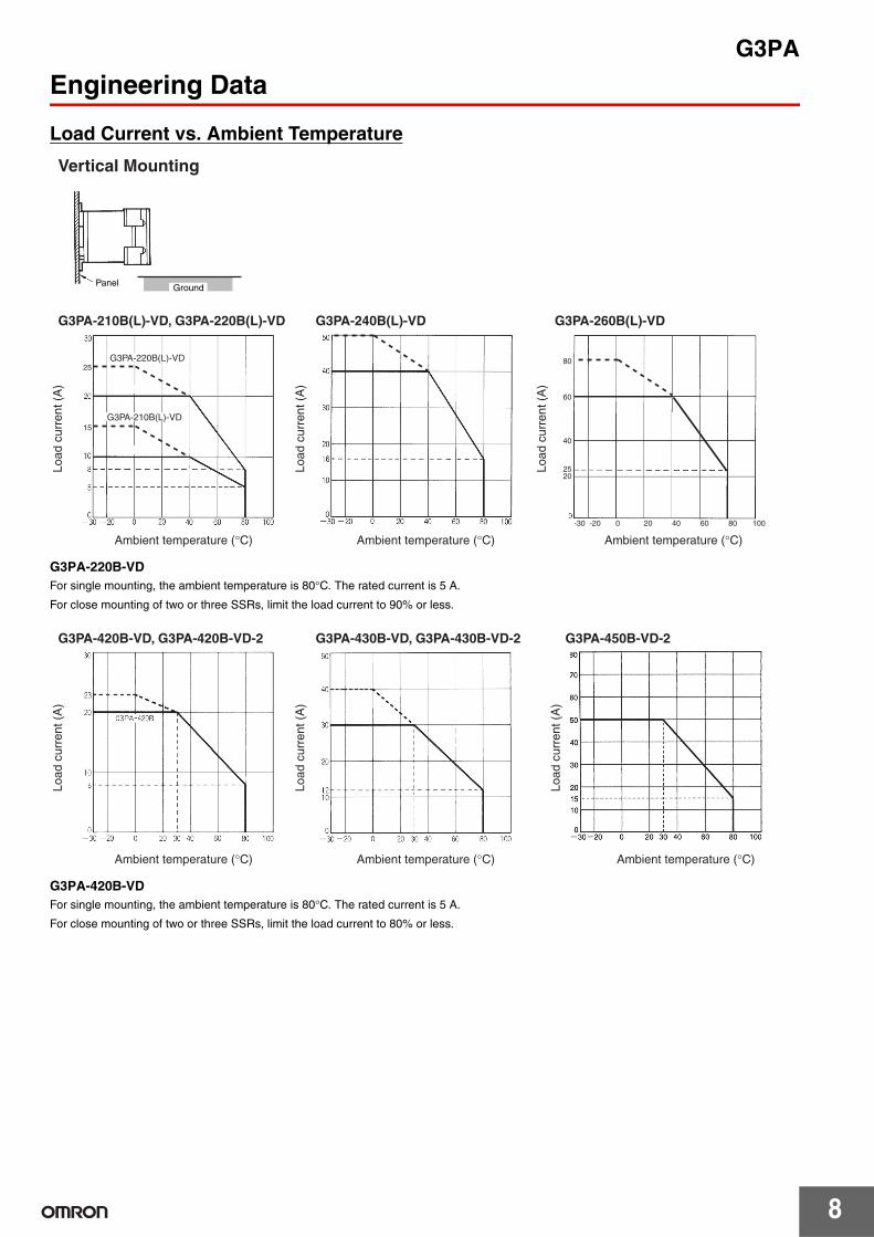
Engineering Data
Load Current vs. Ambient Temperature
G3PA-220B-VDFor single mounting, the ambient temperature is 80°C. The rated current is 5 A.
For close mounting of two or three SSRs, limit the load current to 90% or less.
G3PA-420B-VDFor single mounting, the ambient temperature is 80°C. The rated current is 5 A.
For close mounting of two or three SSRs, limit the load current to 80% or less.
25
15
40 60 80 100200-20-30
60
40
2520
80
Panel Ground
Ambient temperature (°C) Ambient temperature (°C) Ambient temperature (°C)
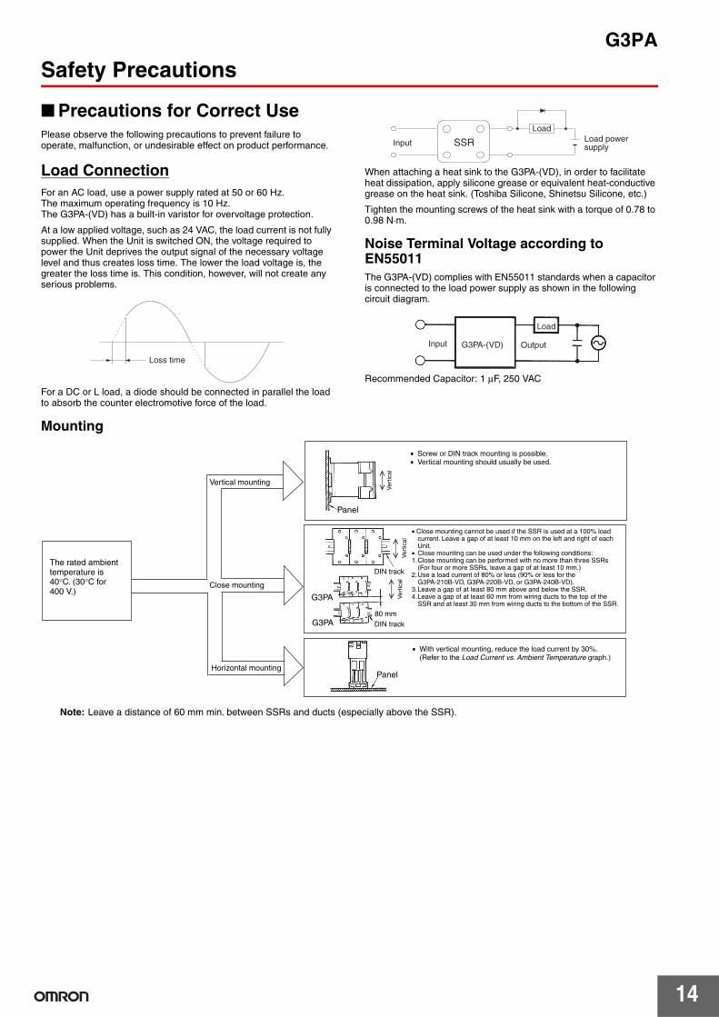
Precautions for Correct UsePlease observe the following precautions to prevent failure to operate, malfunction, or undesirable effect on product performance.
Load ConnectionFor an AC load, use a power supply rated at 50 or 60 Hz.The maximum operating frequency is 10 Hz.The G3PA-(VD) has a built-in varistor for overvoltage protection.
At a low applied voltage, such as 24 VAC, the load current is not fully supplied. When the Unit is switched ON, the voltage required to power the Unit deprives the output signal of the necessary voltage level and thus creates loss time. The lower the load voltage is, the greater the loss time is. This condition, however, will not create any serious problems.
For a DC or L load, a diode should be connected in parallel the load to absorb the counter electromotive force of the load.
When attaching a heat sink to the G3PA-(VD), in order to facilitate heat dissipation, apply silicone grease or equivalent heat-conductive grease on the heat sink. (Toshiba Silicone, Shinetsu Silicone, etc.)
Tighten the mounting screws of the heat sink with a torque of 0.78 to 0.98 N·m.
Noise Terminal Voltage according to EN55011The G3PA-(VD) complies with EN55011 standards when a capacitor is connected to the load power supply as shown in the following circuit diagram.
Recommended Capacitor: 1 µF, 250 VAC
Mounting
Loss time
SSRInput
LoadLoad power supply
G3PA-(VD) Output
Load
Input
DIN track
G3PA
G3PA
Panel
DIN track
Panel
The rated ambient temperature is 40°C. (30°C for 400 V.)
Vertical mounting
Close mounting
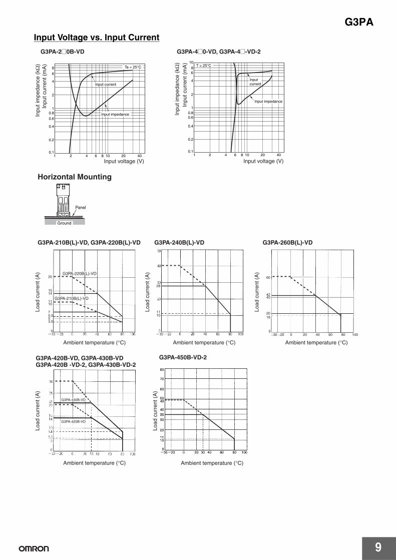
Horizontal mounting
• Screw or DIN track mounting is possible.• Vertical mounting should usually be used.
• Close mounting cannot be used if the SSR is used at a 100% load current. Leave a gap of at least 10 mm on the left and right of each Unit.
• Close mounting can be used under the following conditions: 1. Close mounting can be performed with no more than three SSRs
(For four or more SSRs, leave a gap of at least 10 mm.) 2. Use a load current of 80% or less (90% or less for the
G3PA-210B-VD, G3PA-220B-VD, or G3PA-240B-VD).3. Leave a gap of at least 80 mm above and below the SSR.4. Leave a gap of at least 60 mm from wiring ducts to the top of the
SSR and at least 30 mm from wiring ducts to the bottom of the SSR.
• With vertical mounting, reduce the load current by 30%. (Refer to the Load Current vs. Ambient Temperature graph.)
80 mm
Note: Leave a distance of 60 mm min. between SSRs and ducts (especially above the SSR).
Ver
tical
Ver
tical
Ver
tical
G3PA
15
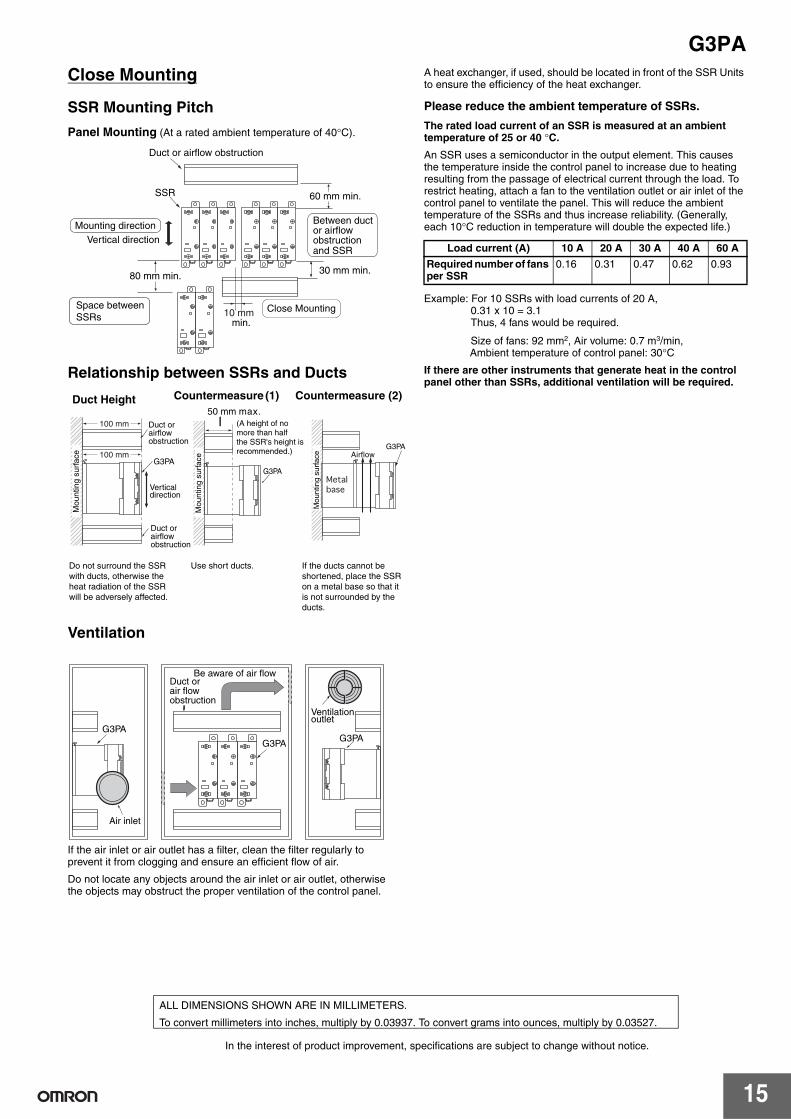
Close Mounting
SSR Mounting Pitch
Panel Mounting (At a rated ambient temperature of 40°C).
Relationship between SSRs and Ducts
Ventilation
If the air inlet or air outlet has a filter, clean the filter regularly to prevent it from clogging and ensure an efficient flow of air.
Do not locate any objects around the air inlet or air outlet, otherwise the objects may obstruct the proper ventilation of the control panel.
A heat exchanger, if used, should be located in front of the SSR Units to ensure the efficiency of the heat exchanger.
Please reduce the ambient temperature of SSRs.
The rated load current of an SSR is measured at an ambient temperature of 25 or 40 °C.
An SSR uses a semiconductor in the output element. This causes the temperature inside the control panel to increase due to heating resulting from the passage of electrical current through the load. To restrict heating, attach a fan to the ventilation outlet or air inlet of the control panel to ventilate the panel. This will reduce the ambient temperature of the SSRs and thus increase reliability. (Generally, each 10°C reduction in temperature will double the expected life.)
Example: For 10 SSRs with load currents of 20 A, 0.31 x 10 = 3.1Thus, 4 fans would be required.
Size of fans: 92 mm2, Air volume: 0.7 m3/min, Ambient temperature of control panel: 30°C
If there are other instruments that generate heat in the control panel other than SSRs, additional ventilation will be required.
SSR
Between duct or airflow obstruction and SSR
60 mm min.
Mounting directionVertical direction
Space betweenSSRs
30 mm min.80 mm min.
min.
Close Mounting
Duct or airflow obstruction
G3PA
G3PA
G3PA
Mou
ntin
g su
rfac
e
Mou
ntin
g su
rfac
e
Mou
ntin
g su
rfac
e
Duct or airflow obstruction
Duct orairflow obstruction
Vertical direction
Airflow
(A height of no more than halfthe SSR's height isrecommended.)
Duct Height
If the ducts cannot be shortened, place the SSR on a metal base so that it is not surrounded by the ducts.
Use short ducts. Do not surround the SSR with ducts, otherwise the heat radiation of the SSR will be adversely affected.
Countermeasure (1) Countermeasure (2) 50 mm max.
G3PA G3PAG3PA
Air inlet
Be aware of air flowDuct or air flow obstruction
Ventilation outlet
Load current (A) 10 A 20 A 30 A 40 A 60 A
Required number of fans per SSR
0.16 0.31 0.47 0.62 0.93
In the interest of product improvement, specifications are subject to change without notice.
ALL DIMENSIONS SHOWN ARE IN MILLIMETERS.
To convert millimeters into inches, multiply by 0.03937. To convert grams into ounces, multiply by 0.03527.