Solid-State Switching Devices for Resistive LoadsSolid-State Relays
General data
4/48 Siemens LV 1 · 2010
4
n Overview
Solid-State Relays
SIRIUS solid-state relays are suitable for surface mounting on existing cooling surfaces. Mounting is quick and easy, involving just two screws. The special technology of the power semicon-ductor ensures there is excellent thermal contact with the heat sink. Depending on the nature of the heat sink, the capacity reaches up to 88 A on resistive loads.
The solid-state relays are available in three different versions:
• 3RF21 single-phase solid-state relay with a width of 22.5 mm
• 3RF20 single-phase solid-state relay with a width of 45 mm
• 3RF22 three-phase solid-state relay with a width of 45 mm
The 3RF21 and 3RF22 solid-state relays can be expanded with various function modules to adapt them to individual applica-tions.
Version for resistive loads, "zero-point switching"
This standard version is often used for switching space heaters on and off.
Version for inductive loads, "instantaneous switching"
In this version the solid-state relay is specifically matched to in-ductive loads. Whether it is a matter of frequent actuation of the valves in a filling plant or starting and stopping small operating mechanisms in packet distribution systems, operation is carried out safely and noiselessly.
Special "Low noise" version
Thanks to a special control circuit, this special version can be used in public networks up to 16 A without any additional mea-sures, such as interference suppressor filters. As a result, in terms of emitted interference, it conforms to limit value curve class B according to EN 60947-4-3.
Single-phase solid-state relays with a width of 22.5 mm
With its compact design and a width of just 22.5 mm, which stays the same even at currents of up to 88 A, the 3RF21 solid-state relay offers an ultra small footprint. The logical connection method, with the power infeed from above and load connection from below, ensures tidy installation in the control cabinet.
Single-phase solid-state relays with a width of 45 mm
The solid-state relays with a width of 45 mm provide for connec-tion of the power supply lead and the load from above. This makes it easy to replace existing solid-state relays in existing ar-rangements. The connection of the control cable also saves space in much the same way as the 22.5 mm design, as it is sim-ply plugged on.
Three-phase solid-state relays with a width of 45 mm
With its compact design and a width of just 45 m, which stays the same even at currents of up to 55 A, the 3RF22 solid-state relay offers an ultra small footprint. The logical connection method, with the power infeed from above and load connection from be-low, ensures tidy installation in the control cabinet.
The three-phase solid-state relays are available with
• two-phase control (suitable in particular for circuits without connection to the neutral conductor) and
• three-phase control (suitable for star circuits with connection to the neutral conductor or for applications in which the system requires all phases to be switched).
Selection notes
When selecting solid-state relays, in addition to information about the network, the load and the ambient conditions it is also necessary to know details of the planned design. The solid-state relays can only conform to their specific technical specifications if they are mounted with appropriate care on an adequately di-mensioned heat sink.
The following procedure is recommended:
• Determine the rated current of the load and the mains voltage
• Select the relay design and choose a solid-state relay with higher rated current than the load
• Determine the thermal resistance of the proposed heat sink
• Check the correct relay size with the aid of the diagrams
Solid-State Switching Devices for Resistive LoadsSolid-State Relays
SIRIUS 3RF21 solid-state relays,single-phase, 22.5 mm
4/49Siemens LV 1 · 2010* You can order this quantity or a multiple thereof.
4
n Selection and ordering data
Other rated control supply voltages on request.1) The type current provides information about the performance capacity of
the solid-state relay. The actual permitted rated operational current Ie can be smaller depend-ing on the connection method and cooling conditions.
2) Please note that this version can only be used for a rated current of up to approx. 50 A and a conductor cross-section of 10 mm2.
3) See page 4/48.
Type current1) Rated control supply voltage Us
DT Screw terminals2) PU(UNIT,
SET, M)
PS* PG Weightper PU
approx.
Order No. Priceper PUA V kg
Zero-point switching Rated operational voltage Ue 24 ... 230 V
3RF21 20-1AA02
20 24 DC acc. to EN 61131-2
A 3RF21 20-1AA02 1 1 unit 101 0.07530 A 3RF21 30-1AA02 1 1 unit 101 0.07550 A 3RF21 50-1AA02 1 1 unit 101 0.07570 A 3RF21 70-1AA02 1 1 unit 101 0.07590 A 3RF21 90-1AA02 1 1 unit 101 0.075
20 110 ... 230 AC A 3RF21 20-1AA22 1 1 unit 101 0.07530 A 3RF21 30-1AA22 1 1 unit 101 0.07550 A 3RF21 50-1AA22 1 1 unit 101 0.07570 A 3RF21 70-1AA22 1 1 unit 101 0.07590 B 3RF21 90-1AA22 1 1 unit 101 0.075
20 4 ... 30 DC B 3RF21 20-1AA42 1 1 unit 101 0.07530 B 3RF21 30-1AA42 1 1 unit 101 0.075
Zero-point switching Rated operational voltage Ue 48 ... 460 V
20 24 DC acc. to EN 61131-2
A 3RF21 20-1AA04 1 1 unit 101 0.07530 A 3RF21 30-1AA04 1 1 unit 101 0.07550 A 3RF21 50-1AA04 1 1 unit 101 0.07570 A 3RF21 70-1AA04 1 1 unit 101 0.07590 A 3RF21 90-1AA04 1 1 unit 101 0.075
20 110 ... 230 AC A 3RF21 20-1AA24 1 1 unit 101 0.07530 A 3RF21 30-1AA24 1 1 unit 101 0.07550 A 3RF21 50-1AA24 1 1 unit 101 0.07570 A 3RF21 70-1AA24 1 1 unit 101 0.07590 A 3RF21 90-1AA24 1 1 unit 101 0.075
Zero-point switching Rated operational voltage Ue 48 ... 600 V
70 24 DC Low Power B 3RF21 70-1AA05-0KN0 1 1 unit 101 0.075
20 4 ... 30 DC B 3RF21 20-1AA45 1 1 unit 101 0.07530 B 3RF21 30-1AA45 1 1 unit 101 0.07550 B 3RF21 50-1AA45 1 1 unit 101 0.07570 B 3RF21 70-1AA45 1 1 unit 101 0.07590 B 3RF21 90-1AA45 1 1 unit 101 0.075
Zero-point switching · Blocking voltage 1600 V, rated operational voltage Ue 48 ... 600 V
30 24 DC acc. to EN 61131-2
A 3RF21 30-1AA06 1 1 unit 101 0.07550 A 3RF21 50-1AA06 1 1 unit 101 0.07570 B 3RF21 70-1AA06 1 1 unit 101 0.07590 B 3RF21 90-1AA06 1 1 unit 101 0.075
30 110 ... 230 AC B 3RF21 30-1AA26 1 1 unit 101 0.07550 B 3RF21 50-1AA26 1 1 unit 101 0.07570 B 3RF21 70-1AA26 1 1 unit 101 0.07590 B 3RF21 90-1AA26 1 1 unit 101 0.075
Instantaneous switching Rated operational voltage Ue 24 ... 230 V
50 110 ... 230 AC A 3RF21 50-1BA22 1 1 unit 101 0.075
Instantaneous switching Rated operational voltage Ue 48 ... 460 V
20 24 DC acc. to EN 61131-2
B 3RF21 20-1BA04 1 1 unit 101 0.07530 B 3RF21 30-1BA04 1 1 unit 101 0.07550 B 3RF21 50-1BA04 1 1 unit 101 0.07570 A 3RF21 70-1BA04 1 1 unit 101 0.07590 B 3RF21 90-1BA04 1 1 unit 101 0.075
Instantaneous switching · Blocking voltage 1600 V Rated operational voltage Ue 48 ... 600 V
50 24 DC acc. to EN 61131-2
B 3RF21 50-1BA06 1 1 unit 101 0.075
Low noise3) · Zero-point switching Rated operational voltage Ue 48 ... 460 V
Solid-State Switching Devices for Resistive LoadsSolid-State RelaysSIRIUS 3RF21 solid-state relays,single-phase, 22.5 mm
4/50 Siemens LV 1 · 2010* You can order this quantity or a multiple thereof.
4
Other rated control supply voltages on request.1) The type current provides information about the performance capacity of
the solid-state relay. The actual permitted rated operational current Ie can be smaller depend-ing on the connection method and cooling conditions.
2) Please note that the version with spring-type terminals can only be used for a rated current of up to approx. 20 A and a conductor cross-section of 2.5 mm2. Higher currents are possible by connecting two conductors per terminal.
Type current1) Rated control supply voltage Us
DT Spring-type terminals2) PU(UNIT,
SET, M)
PS* PG Weightper PU
approx.
Order No. Priceper PUA V kg
Zero-point switching Rated operational voltage Ue 24 ... 230 V
3RF21 20-2AA02
20 24 DC acc. to EN 61131-2
A 3RF21 20-2AA02 1 1 unit 101 0.07550 B 3RF21 50-2AA02 1 1 unit 101 0.07590 B 3RF21 90-2AA02 1 1 unit 101 0.075
20 110 ... 230 AC B 3RF21 20-2AA22 1 1 unit 101 0.07550 B 3RF21 50-2AA22 1 1 unit 101 0.07590 B 3RF21 90-2AA22 1 1 unit 101 0.075
20 4 ... 30 DC B 3RF21 20-2AA42 1 1 unit 101 0.075
Zero-point switching Rated operational voltage Ue 48 ... 460 V
20 24 DC acc. to EN 61131-2
B 3RF21 20-2AA04 1 1 unit 101 0.07550 B 3RF21 50-2AA04 1 1 unit 101 0.07590 B 3RF21 90-2AA04 1 1 unit 101 0.075
50 24 AC/DC B 3RF21 50-2AA14 1 1 unit 101 0.075
20 110 ... 230 AC B 3RF21 20-2AA24 1 1 unit 101 0.07550 B 3RF21 50-2AA24 1 1 unit 101 0.07590 B 3RF21 90-2AA24 1 1 unit 101 0.075
Zero-point switching Rated operational voltage Ue 48 ... 600 V
20 4 ... 30 DC B 3RF21 20-2AA45 1 1 unit 101 0.075
Zero-point switching · Blocking voltage 1600 V, rated operational voltage Ue 48 ... 600 V
50 24 DC acc. to EN 61131-2
B 3RF21 50-2AA06 1 1 unit 101 0.07590 B 3RF21 90-2AA06 1 1 unit 101 0.075
50 110 ... 230 AC B 3RF21 50-2AA26 1 1 unit 101 0.07590 B 3RF21 90-2AA26 1 1 unit 101 0.075
Solid-State Switching Devices for Resistive LoadsSolid-State RelaysSIRIUS 3RF20 solid-state relays,single-phase, 45 mm
4/52 Siemens LV 1 · 2010* You can order this quantity or a multiple thereof.
4
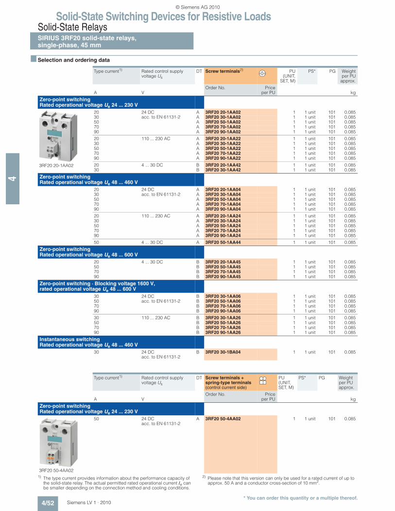
n Selection and ordering data
1) The type current provides information about the performance capacity of the solid-state relay. The actual permitted rated operational current Ie can be smaller depending on the connection method and cooling conditions.
2) Please note that this version can only be used for a rated current of up to approx. 50 A and a conductor cross-section of 10 mm2.
Type current1) Rated control supply voltage Us
DT Screw terminals2) PU(UNIT,
SET, M)
PS* PG Weightper PU
approx.
Order No. Priceper PUA V kg
Zero-point switching Rated operational voltage Ue 24 ... 230 V
3RF20 20-1AA02
20 24 DC acc. to EN 61131-2
A 3RF20 20-1AA02 1 1 unit 101 0.08530 A 3RF20 30-1AA02 1 1 unit 101 0.08550 A 3RF20 50-1AA02 1 1 unit 101 0.08570 A 3RF20 70-1AA02 1 1 unit 101 0.08590 A 3RF20 90-1AA02 1 1 unit 101 0.085
20 110 ... 230 AC A 3RF20 20-1AA22 1 1 unit 101 0.08530 A 3RF20 30-1AA22 1 1 unit 101 0.08550 A 3RF20 50-1AA22 1 1 unit 101 0.08570 A 3RF20 70-1AA22 1 1 unit 101 0.08590 A 3RF20 90-1AA22 1 1 unit 101 0.085
20 4 ... 30 DC B 3RF20 20-1AA42 1 1 unit 101 0.08530 B 3RF20 30-1AA42 1 1 unit 101 0.085
Zero-point switching Rated operational voltage Ue 48 ... 460 V
20 24 DC acc. to EN 61131-2
A 3RF20 20-1AA04 1 1 unit 101 0.08530 A 3RF20 30-1AA04 1 1 unit 101 0.08550 A 3RF20 50-1AA04 1 1 unit 101 0.08570 A 3RF20 70-1AA04 1 1 unit 101 0.08590 A 3RF20 90-1AA04 1 1 unit 101 0.085
20 110 ... 230 AC A 3RF20 20-1AA24 1 1 unit 101 0.08530 A 3RF20 30-1AA24 1 1 unit 101 0.08550 A 3RF20 50-1AA24 1 1 unit 101 0.08570 A 3RF20 70-1AA24 1 1 unit 101 0.08590 A 3RF20 90-1AA24 1 1 unit 101 0.085
50 4 ... 30 DC A 3RF20 50-1AA44 1 1 unit 101 0.085
Zero-point switching Rated operational voltage Ue 48 ... 600 V
20 4 ... 30 DC B 3RF20 20-1AA45 1 1 unit 101 0.08550 B 3RF20 50-1AA45 1 1 unit 101 0.08570 B 3RF20 70-1AA45 1 1 unit 101 0.08590 B 3RF20 90-1AA45 1 1 unit 101 0.085
Zero-point switching · Blocking voltage 1600 V, rated operational voltage Ue 48 ... 600 V
30 24 DC acc. to EN 61131-2
B 3RF20 30-1AA06 1 1 unit 101 0.08550 B 3RF20 50-1AA06 1 1 unit 101 0.08570 B 3RF20 70-1AA06 1 1 unit 101 0.08590 B 3RF20 90-1AA06 1 1 unit 101 0.085
30 110 ... 230 AC B 3RF20 30-1AA26 1 1 unit 101 0.08550 B 3RF20 50-1AA26 1 1 unit 101 0.08570 B 3RF20 70-1AA26 1 1 unit 101 0.08590 B 3RF20 90-1AA26 1 1 unit 101 0.085
Instantaneous switching Rated operational voltage Ue 48 ... 460 V
30 24 DC acc. to EN 61131-2
B 3RF20 30-1BA04 1 1 unit 101 0.085
Type current1) Rated control supply voltage Us
DT Screw terminals + spring-type terminals (control current side)
PU (UNIT, SET, M)
PS* PG Weight per PU approx.
Order No. Priceper PUA V kg
Zero-point switching Rated operational voltage Ue 24 ... 230 V
Solid-State Switching Devices for Resistive LoadsSolid-State Relays
SIRIUS 3RF22 solid-state relays,three-phase, 45 mm
4/53Siemens LV 1 · 2010* You can order this quantity or a multiple thereof.
4
n Selection and ordering data
1) The type current provides information about the performance capacity of the solid-state relay. The actual permitted rated operational current Ie can be smaller depend-ing on the connection method and cooling conditions.
2) Please note that the version with an M4 screw connection can only be used for a rated current of up to approx. 50 A and a conductor cross-section of 10 mm2.
3) Please note that the version with spring-type terminals can only be used for a rated current of up to approx. 20 A and a conductor cross-section of 2.5 mm2. Higher currents are possible by connecting two conductors per terminal.
Type current1) Rated control supply voltage Us
DT Screw terminals2) PU(UNIT,
SET, M)
PS* PG Weightper PU
approx.
Order No. Priceper PUA V kg
Zero-point switching Rated operational voltage Ue 48 ... 600 V
3RF22 30-1AB45
Two-phase controlled
30 110 AC B 3RF22 30-1AB35 1 1 unit 101 0.150
55 B 3RF22 55-1AB35 1 1 unit 101 0.150
30 4 ... 30 DC B 3RF22 30-1AB45 1 1 unit 101 0.150
55 B 3RF22 55-1AB45 1 1 unit 101 0.150
Three-phase controlled
30 110 AC B 3RF22 30-1AC35 1 1 unit 101 0.150
55 B 3RF22 55-1AC35 1 1 unit 101 0.150
30 4 ... 30 DC A 3RF22 30-1AC45 1 1 unit 101 0.150
55 B 3RF22 55-1AC45 1 1 unit 101 0.150
Type current1) Rated control supply voltage Us
DT Spring-type terminals3) PU(UNIT,
SET, M)
PS* PG Weightper PU
approx.
Order No. Priceper PUA V kg
Zero-point switching Rated operational voltage Ue 48 ... 600 V
3RF22 30-2AB45
Two-phase controlled
30 4 ... 30 DC B 3RF22 30-2AB45 1 1 unit 101 0.150
55 B 3RF22 55-2AB45 1 1 unit 101 0.150
Three-phase controlled
30 4 ... 30 DC B 3RF22 30-2AC45 1 1 unit 101 0.150
55 B 3RF22 55-2AC45 1 1 unit 101 0.150
Type current1) Rated control supply voltage Us
DT Ring terminal lug con-nection
PU(UNIT,
SET, M)
PS* PG Weightper PU
approx.
Order No. Priceper PUA V kg
Zero-point switching Rated operational voltage Ue 48 ... 600 V
3RF22 30-3AB45
Two-phase controlled
30 4 ... 30 DC B 3RF22 30-3AB45 1 1 unit 101 0.150
55 B 3RF22 55-3AB45 1 1 unit 101 0.150
Three-phase controlled
30 4 ... 30 DC B 3RF22 30-3AC45 1 1 unit 101 0.150
Solid-State Switching Devices for Resistive LoadsSolid-State Contactors
General data
4/54 Siemens LV 1 · 2010
4
n Overview
Solid-State Contactors
The complete units consist of a solid-state relay plus optimized heat sink, and are therefore ready to use. They offer defined rated currents to make selection as easy as possible. Depend-ing on the version, current strengths of up to 88 A are achieved. Like all of our solid-state switching devices, one of their particu-lar advantages is their compact and space-saving design.
With their insulated mounting foot they can easily be snapped onto a standard mounting rail, or they can be mounted on sup-port plates with fixing screws. This insulation enables them to be used in circuits with protective extra-low voltage (PELV) or safety extra-low voltage (SELV) in building management systems. For other applications, such as for extended personal safety, the heat sink can be grounded through a screw terminal.
The solid-state contactors are available in 2 different versions:
• 3RF23 single-phase solid-state contactors,
• 3RF24 three-phase solid-state contactors
Single-phase versions
The 3RF23 solid-state contactors can be expanded with various function modules to adapt them to individual applications.
Version for resistive loads, "zero-point switching"
This standard version is often used for switching space heaters on and off.
Version for inductive loads, "instantaneous switching"
In this version the solid-state contactor is specifically matched to inductive loads. Whether it is a matter of frequent actuation of the valves in a filling plant or starting and stopping small operating mechanisms in packet distribution systems, operation is carried out safely and noiselessly.
Special "Low noise" version
Thanks to a special control circuit, this special version can be used in public networks up to 16 A without any additional mea-sures, such as interference suppressor filters. As a result, in terms of emitted interference, it conforms to limit value curve class B according to EN 60947-4-3.
Special "Short-circuit proof" version
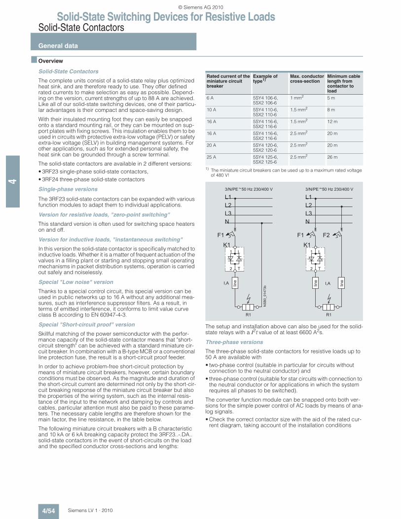
Skillful matching of the power semiconductor with the perfor-mance capacity of the solid-state contactor means that "short-circuit strength" can be achieved with a standard miniature cir-cuit breaker. In combination with a B-type MCB or a conventional line protection fuse, the result is a short-circuit proof feeder.
In order to achieve problem-free short-circuit protection by means of miniature circuit breakers, however, certain boundary conditions must be observed. As the magnitude and duration of the short-circuit current are determined not only by the short-cir-cuit breaking response of the miniature circuit breaker but also the properties of the wiring system, such as the internal resis-tance of the input to the network and damping by controls and cables, particular attention must also be paid to these parame-ters. The necessary cable lengths are therefore shown for the main factor, the line resistance, in the table below.
The following miniature circuit breakers with a B characteristic and 10 kA or 6 kA breaking capacity protect the 3RF23..-.DA.. solid-state contactors in the event of short-circuits on the load and the specified conductor cross-sections and lengths:
1) The miniature circuit breakers can be used up to a maximum rated voltage of 480 V!
The setup and installation above can also be used for the solid-state relays with a I2t value of at least 6600 A2s.
Three-phase versions
The three-phase solid-state contactors for resistive loads up to 50 A are available with
• two-phase control (suitable in particular for circuits without connection to the neutral conductor) and
• three-phase control (suitable for star circuits with connection to the neutral conductor or for applications in which the system requires all phases to be switched).
The converter function module can be snapped onto both ver-sions for the simple power control of AC loads by means of ana-log signals.
• Check the correct contactor size with the aid of the rated cur-rent diagram, taking account of the installation conditions
Solid-State Switching Devices for Resistive LoadsSolid-State Contactors
SIRIUS 3RF23 solid-state contactors,single-phase
4/55Siemens LV 1 · 2010* You can order this quantity or a multiple thereof.
4
n Selection and ordering data
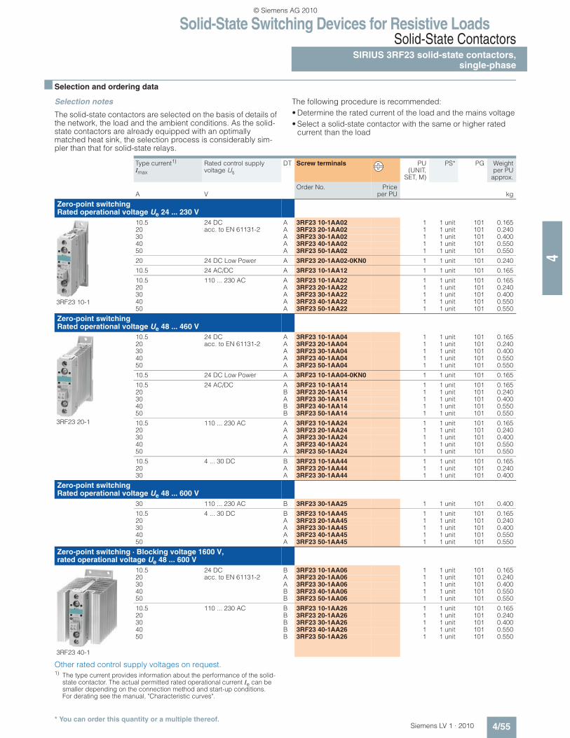
Selection notes
The solid-state contactors are selected on the basis of details of the network, the load and the ambient conditions. As the solid-state contactors are already equipped with an optimally matched heat sink, the selection process is considerably sim-pler than that for solid-state relays.
The following procedure is recommended:
• Determine the rated current of the load and the mains voltage
• Select a solid-state contactor with the same or higher rated current than the load
Other rated control supply voltages on request.1) The type current provides information about the performance of the solid-
state contactor. The actual permitted rated operational current Ie can be smaller depending on the connection method and start-up conditions. For derating see the manual, "Characteristic curves".
Type current1)
Imax
Rated control supply voltage Us
DT Screw terminals PU(UNIT,
SET, M)
PS* PG Weightper PU
approx.
Order No. Priceper PUA V kg
Zero-point switching Rated operational voltage Ue 24 ... 230 V
3RF23 10-1
10.5 24 DC acc. to EN 61131-2
A 3RF23 10-1AA02 1 1 unit 101 0.16520 A 3RF23 20-1AA02 1 1 unit 101 0.24030 A 3RF23 30-1AA02 1 1 unit 101 0.40040 A 3RF23 40-1AA02 1 1 unit 101 0.55050 A 3RF23 50-1AA02 1 1 unit 101 0.550
20 24 DC Low Power A 3RF23 20-1AA02-0KN0 1 1 unit 101 0.240
10.5 24 AC/DC A 3RF23 10-1AA12 1 1 unit 101 0.165
10.5 110 ... 230 AC A 3RF23 10-1AA22 1 1 unit 101 0.16520 A 3RF23 20-1AA22 1 1 unit 101 0.24030 A 3RF23 30-1AA22 1 1 unit 101 0.40040 A 3RF23 40-1AA22 1 1 unit 101 0.55050 A 3RF23 50-1AA22 1 1 unit 101 0.550
Zero-point switching Rated operational voltage Ue 48 ... 460 V
3RF23 20-1
10.5 24 DC acc. to EN 61131-2
A 3RF23 10-1AA04 1 1 unit 101 0.16520 A 3RF23 20-1AA04 1 1 unit 101 0.24030 A 3RF23 30-1AA04 1 1 unit 101 0.40040 A 3RF23 40-1AA04 1 1 unit 101 0.55050 A 3RF23 50-1AA04 1 1 unit 101 0.550
10.5 24 DC Low Power A 3RF23 10-1AA04-0KN0 1 1 unit 101 0.165
10.5 24 AC/DC A 3RF23 10-1AA14 1 1 unit 101 0.16520 B 3RF23 20-1AA14 1 1 unit 101 0.24030 A 3RF23 30-1AA14 1 1 unit 101 0.40040 B 3RF23 40-1AA14 1 1 unit 101 0.55050 B 3RF23 50-1AA14 1 1 unit 101 0.550
10.5 110 ... 230 AC A 3RF23 10-1AA24 1 1 unit 101 0.16520 A 3RF23 20-1AA24 1 1 unit 101 0.24030 A 3RF23 30-1AA24 1 1 unit 101 0.40040 A 3RF23 40-1AA24 1 1 unit 101 0.55050 A 3RF23 50-1AA24 1 1 unit 101 0.550
10.5 4 ... 30 DC B 3RF23 10-1AA44 1 1 unit 101 0.16520 A 3RF23 20-1AA44 1 1 unit 101 0.24030 A 3RF23 30-1AA44 1 1 unit 101 0.400
Zero-point switching Rated operational voltage Ue 48 ... 600 V
30 110 ... 230 AC B 3RF23 30-1AA25 1 1 unit 101 0.400
10.5 4 ... 30 DC B 3RF23 10-1AA45 1 1 unit 101 0.16520 A 3RF23 20-1AA45 1 1 unit 101 0.24030 A 3RF23 30-1AA45 1 1 unit 101 0.40040 A 3RF23 40-1AA45 1 1 unit 101 0.55050 A 3RF23 50-1AA45 1 1 unit 101 0.550
Zero-point switching · Blocking voltage 1600 V, rated operational voltage Ue 48 ... 600 V
3RF23 40-1
10.5 24 DC acc. to EN 61131-2
B 3RF23 10-1AA06 1 1 unit 101 0.16520 A 3RF23 20-1AA06 1 1 unit 101 0.24030 A 3RF23 30-1AA06 1 1 unit 101 0.40040 B 3RF23 40-1AA06 1 1 unit 101 0.55050 B 3RF23 50-1AA06 1 1 unit 101 0.550
10.5 110 ... 230 AC B 3RF23 10-1AA26 1 1 unit 101 0.16520 B 3RF23 20-1AA26 1 1 unit 101 0.24030 B 3RF23 30-1AA26 1 1 unit 101 0.40040 B 3RF23 40-1AA26 1 1 unit 101 0.55050 B 3RF23 50-1AA26 1 1 unit 101 0.550
Solid-State Switching Devices for Resistive LoadsSolid-State ContactorsSIRIUS 3RF23 solid-state contactors,single-phase
4/56 Siemens LV 1 · 2010* You can order this quantity or a multiple thereof.
4
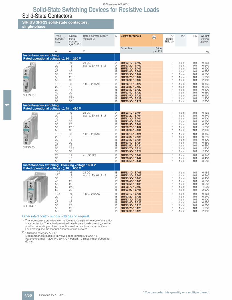
Other rated control supply voltages on request.1) The type current provides information about the performance of the solid-
state contactor. The actual permitted rated operational current Ie can be smaller depending on the connection method and start-up conditions. For derating see the manual, "Characteristic curves".
2) Utilization category AC-15: Electromagnetic loads, e. g. valves according to EN 60947-5. Parameters: max. 1200 1/h, 50 % ON Period, 10-times inrush current for 60 ms.
Type current1)
Imax
Opera-tional current Ie/AC-152)
Rated control supply voltage Us
DT Screw terminals PU(UNIT,
SET, M)
PS* PG Weightper PU
approx.
Order No. Priceper PUA A V kg
Instantaneous switching Rated operational voltage Ue 24 ... 230 V
3RF23 10-1
10.5 6 24 DC acc. to EN 61131-2
A 3RF23 10-1BA02 1 1 unit 101 0.16520 12 A 3RF23 20-1BA02 1 1 unit 101 0.24030 15 B 3RF23 30-1BA02 1 1 unit 101 0.40040 20 B 3RF23 40-1BA02 1 1 unit 101 0.55050 25 B 3RF23 50-1BA02 1 1 unit 101 0.55050 27.5 B 3RF23 70-1BA02 1 1 unit 101 1.20050 30 B 3RF23 90-1BA02 1 1 unit 101 2.900
10.5 6 110 ... 230 AC B 3RF23 10-1BA22 1 1 unit 101 0.16520 12 B 3RF23 20-1BA22 1 1 unit 101 0.24030 15 B 3RF23 30-1BA22 1 1 unit 101 0.40040 20 B 3RF23 40-1BA22 1 1 unit 101 0.55050 25 B 3RF23 50-1BA22 1 1 unit 101 0.55050 27.5 B 3RF23 70-1BA22 1 1 unit 101 1.20050 30 B 3RF23 90-1BA22 1 1 unit 101 2.900
Instantaneous switching Rated operational voltage Ue 48 ... 460 V
3RF23 20-1
10.5 6 24 DC acc. to EN 61131-2
A 3RF23 10-1BA04 1 1 unit 101 0.16520 12 A 3RF23 20-1BA04 1 1 unit 101 0.24030 15 A 3RF23 30-1BA04 1 1 unit 101 0.40040 20 B 3RF23 40-1BA04 1 1 unit 101 0.55050 25 B 3RF23 50-1BA04 1 1 unit 101 0.55050 27.5 B 3RF23 70-1BA04 1 1 unit 101 1.20050 30 B 3RF23 90-1BA04 1 1 unit 101 2.900
10.5 6 110 ... 230 AC B 3RF23 10-1BA24 1 1 unit 101 0.16520 12 B 3RF23 20-1BA24 1 1 unit 101 0.24030 15 B 3RF23 30-1BA24 1 1 unit 101 0.40040 20 B 3RF23 40-1BA24 1 1 unit 101 0.55050 25 B 3RF23 50-1BA24 1 1 unit 101 0.55050 27.5 B 3RF23 70-1BA24 1 1 unit 101 1.20050 30 B 3RF23 90-1BA24 1 1 unit 101 2.900
20 12 4 ... 30 DC B 3RF23 20-1BA44 1 1 unit 101 0.24030 15 B 3RF23 30-1BA44 1 1 unit 101 0.40050 25 B 3RF23 50-1BA44 1 1 unit 101 0.550
Instantaneous switching · Blocking voltage 1600 V Rated operational voltage Ue 48 ... 600 V
3RF23 40-1
10.5 6 24 DC acc. to EN 61131-2
B 3RF23 10-1BA06 1 1 unit 101 0.16520 12 A 3RF23 20-1BA06 1 1 unit 101 0.24030 15 B 3RF23 30-1BA06 1 1 unit 101 0.40040 20 B 3RF23 40-1BA06 1 1 unit 101 0.55050 25 B 3RF23 50-1BA06 1 1 unit 101 0.55050 27.5 B 3RF23 70-1BA06 1 1 unit 101 1.20050 30 B 3RF23 90-1BA06 1 1 unit 101 2.900
10.5 6 110 ... 230 AC B 3RF23 10-1BA26 1 1 unit 101 0.16520 12 B 3RF23 20-1BA26 1 1 unit 101 0.24030 15 B 3RF23 30-1BA26 1 1 unit 101 0.40040 20 B 3RF23 40-1BA26 1 1 unit 101 0.55050 25 B 3RF23 50-1BA26 1 1 unit 101 0.55050 27.5 B 3RF23 70-1BA26 1 1 unit 101 1.20050 30 B 3RF23 90-1BA26 1 1 unit 101 2.900
Solid-State Switching Devices for Resistive LoadsSolid-State Contactors
SIRIUS 3RF23 solid-state contactors,single-phase
4/57Siemens LV 1 · 2010* You can order this quantity or a multiple thereof.
4
Other rated control supply voltages on request.1) The type current provides information about the performance of the solid-
state contactor. The actual permitted rated operational current Ie can be smaller depending on the connection method and start-up conditions. For derating see the manual, "Characteristic curves".
2) See page 4/54.
Type current1)
Imax
Rated control supply voltage Us
DT Screw terminals PU(UNIT,
SET, M)
PS* PG Weightper PU
approx.
Order No. Priceper PUA V kg
Low noise2) · Zero-point switching Rated operational voltage Ue 24 ... 230 V
3RF23 20-1
20 24 DC acc. to EN 61131-2
B 3RF23 20-1CA02 1 1 unit 101 0.24030 B 3RF23 30-1CA02 1 1 unit 101 0.400
20 110 ... 230 AC B 3RF23 20-1CA22 1 1 unit 101 0.240
Low noise2) · Zero-point switching Rated operational voltage Ue 48 ... 460 V
20 24 DC acc. to EN 61131-2
B 3RF23 20-1CA04 1 1 unit 101 0.240
20 110 ... 230 AC B 3RF23 20-1CA24 1 1 unit 101 0.240
20 4 ... 30 DC A 3RF23 20-1CA44 1 1 unit 101 0.240
Short-circuit proof with B-type MCB · Zero-point switching, rated operational voltage Ue 24 ... 230 V
20 24 DC acc. to EN 61131-2
A 3RF23 20-1DA02 1 1 unit 101 0.240
20 110 ... 230 AC B 3RF23 20-1DA22 1 1 unit 101 0.240
Short-circuit proof with B-type MCB · Zero-point switching, rated operational voltage Ue 48 ... 460 V
20 24 DC acc. to EN 61131-2
A 3RF23 20-1DA04 1 1 unit 101 0.240
20 110 ... 230 AC B 3RF23 20-1DA24 1 1 unit 101 0.240
20 4 ... 30 DC A 3RF23 20-1DA44 1 1 unit 101 0.24030 A 3RF23 30-1DA44 1 1 unit 101 0.240
Solid-State Switching Devices for Resistive LoadsSolid-State ContactorsSIRIUS 3RF23 solid-state contactors,single-phase
4/58 Siemens LV 1 · 2010* You can order this quantity or a multiple thereof.
4
Other rated control supply voltages on request.1) The type current provides information about the performance of the solid-
state contactor. The actual permitted rated operational current Ie can be smaller depending on the connection method and start-up conditions. For derating see the manual, "Characteristic curves".
2) See page 4/54.
Type current1)
Imax
Rated control supply voltage Us
DT Spring-type terminals PU(UNIT,
SET, M)
PS* PG Weightper PU
approx.
Order No. Priceper PUA V kg
Zero-point switching Rated operational voltage Ue 24 ... 230 V
3RF23 20-2
10.5 24 DC acc. to EN 61131-2
B 3RF23 10-2AA02 1 1 unit 101 0.16620 A 3RF23 20-2AA02 1 1 unit 101 0.240
10.5 110 ... 230 AC B 3RF23 10-2AA22 1 1 unit 101 0.16620 B 3RF23 20-2AA22 1 1 unit 101 0.240
Zero-point switching Rated operational voltage Ue 48 ... 460 V
10.5 24 DC acc. to EN 61131-2
A 3RF23 10-2AA04 1 1 unit 101 0.16620 A 3RF23 20-2AA04 1 1 unit 101 0.240
10.5 110 ... 230 AC B 3RF23 10-2AA24 1 1 unit 101 0.16620 B 3RF23 20-2AA24 1 1 unit 101 0.240
Zero-point switching · Blocking voltage 1600 V, rated operational voltage Ue 48 ... 600 V
10.5 24 DC acc. to EN 61131-2
B 3RF23 10-2AA06 1 1 unit 101 0.16620 A 3RF23 20-2AA06 1 1 unit 101 0.240
10.5 110 ... 230 AC B 3RF23 10-2AA26 1 1 unit 101 0.16620 B 3RF23 20-2AA26 1 1 unit 101 0.240
Low noise2) · Zero-point switching Rated operational voltage Ue 24 ... 230 V
20 24 DC acc. to EN 61131-2
B 3RF23 20-2CA02 1 1 unit 101 0.240
20 110 ... 230 AC B 3RF23 20-2CA22 1 1 unit 101 0.240
Low noise2) · Zero-point switching Rated operational voltage Ue 48 ... 460 V
20 24 DC acc. to EN 61131-2
B 3RF23 20-2CA04 1 1 unit 101 0.240
20 110 ... 230 AC B 3RF23 20-2CA24 1 1 unit 101 0.240
Short-circuit proof with B-type MCB · Zero-point switching, rated operational voltage Ue 24 ... 230 V
20 110 ... 230 AC B 3RF23 20-2DA22 1 1 unit 101 0.240
Short-circuit proof with B-type MCB · Zero-point switching, rated operational voltage Ue 48 ... 460 V
20 110 ... 230 AC B 3RF23 20-2DA24 1 1 unit 101 0.240
Solid-State Switching Devices for Resistive LoadsSolid-State Contactors
SIRIUS 3RF23 solid-state contactors,single-phase
4/59Siemens LV 1 · 2010* You can order this quantity or a multiple thereof.
4
Other rated control supply voltages on request.1) The type current provides information about the performance of the solid-
state contactor. The actual permitted rated operational current Ie can be smaller depending on the connection method and start-up conditions. For derating see the manual, "Characteristic curves".
Type current1)
Imax
Rated control supply voltage Us
DT Ring terminal lug connection
PU(UNIT,
SET, M)
PS* PG Weightper PU
approx.
Order No. Priceper PUA V kg
Zero-point switching Rated operational voltage Ue 24 ... 230 V
3RF23 30-3
10.5 24 DC acc. to EN 61131-2
B 3RF23 10-3AA02 1 1 unit 101 0.16620 B 3RF23 20-3AA02 1 1 unit 101 0.20030 B 3RF23 30-3AA02 1 1 unit 101 0.43540 B 3RF23 40-3AA02 1 1 unit 101 0.55050 B 3RF23 50-3AA02 1 1 unit 101 0.55070 A 3RF23 70-3AA02 1 1 unit 101 1.20088 B 3RF23 90-3AA02 1 1 unit 101 2.900
10.5 110 ... 230 AC B 3RF23 10-3AA22 1 1 unit 101 0.16620 B 3RF23 20-3AA22 1 1 unit 101 0.20030 B 3RF23 30-3AA22 1 1 unit 101 0.43540 B 3RF23 40-3AA22 1 1 unit 101 0.55050 B 3RF23 50-3AA22 1 1 unit 101 0.55070 B 3RF23 70-3AA22 1 1 unit 101 1.20088 B 3RF23 90-3AA22 1 1 unit 101 2.900
Zero-point switching Rated operational voltage Ue 48 ... 460 V
10.5 24 DC acc. to EN 61131-2
B 3RF23 10-3AA04 1 1 unit 101 0.16620 B 3RF23 20-3AA04 1 1 unit 101 0.20030 A 3RF23 30-3AA04 1 1 unit 101 0.43540 B 3RF23 40-3AA04 1 1 unit 101 0.55050 B 3RF23 50-3AA04 1 1 unit 101 0.55070 A 3RF23 70-3AA04 1 1 unit 101 1.20088 A 3RF23 90-3AA04 1 1 unit 101 2.900
10.5 110 ... 230 AC B 3RF23 10-3AA24 1 1 unit 101 0.16620 B 3RF23 20-3AA24 1 1 unit 101 0.20030 B 3RF23 30-3AA24 1 1 unit 101 0.43540 B 3RF23 40-3AA24 1 1 unit 101 0.55050 B 3RF23 50-3AA24 1 1 unit 101 0.55070 B 3RF23 70-3AA24 1 1 unit 101 1.20088 B 3RF23 90-3AA24 1 1 unit 101 2.900
20 4 ... 30 DC B 3RF23 20-3AA44 1 1 unit 101 0.20030 B 3RF23 30-3AA44 1 1 unit 101 0.43550 B 3RF23 50-3AA44 1 1 unit 101 0.550
Zero-point switching Rated operational voltage Ue 48 ... 600 V
40 4 ... 30 DC B 3RF23 40-3AA45 1 1 unit 101 0.55070 A 3RF23 70-3AA45 1 1 unit 101 1.20088 B 3RF23 90-3AA45 1 1 unit 101 2.900
Zero-point switching · Blocking voltage 1600 V, rated operational voltage Ue 48 ... 600 V
10.5 24 DC acc. to EN 61131-2
B 3RF23 10-3AA06 1 1 unit 101 0.16620 B 3RF23 20-3AA06 1 1 unit 101 0.20030 B 3RF23 30-3AA06 1 1 unit 101 0.43540 B 3RF23 40-3AA06 1 1 unit 101 0.55050 B 3RF23 50-3AA06 1 1 unit 101 0.55070 B 3RF23 70-3AA06 1 1 unit 101 1.20088 B 3RF23 90-3AA06 1 1 unit 101 2.900
10.5 110 ... 230 AC B 3RF23 10-3AA26 1 1 unit 101 0.16620 B 3RF23 20-3AA26 1 1 unit 101 0.20030 B 3RF23 30-3AA26 1 1 unit 101 0.43540 B 3RF23 40-3AA26 1 1 unit 101 0.55050 B 3RF23 50-3AA26 1 1 unit 101 0.55070 A 3RF23 70-3AA26 1 1 unit 101 1.20088 B 3RF23 90-3AA26 1 1 unit 101 2.900
Solid-State Switching Devices for Resistive LoadsSolid-State ContactorsSIRIUS 3RF23 solid-state contactors,single-phase
4/60 Siemens LV 1 · 2010* You can order this quantity or a multiple thereof.
4
Other rated control supply voltages on request.1) The type current provides information about the performance of the solid-
state contactor. The actual permitted rated operational current Ie can be smaller depending on the connection method and start-up conditions. For derating see the manual, "Characteristic curves".
2) Utilization category AC-15: Electromagnetic loads, e. g. valves according to EN 60947-5. Parameters: max. 1200 1/h, 50 % ON Period, 10-times inrush current for 60 ms.
Type current1)
Imax
Opera-tional current Ie/AC-152)
Rated control supply voltage Us
DT Ring terminal lug connection
PU(UNIT,
SET, M)
PS* PG Weightper PU
approx.
Order No. Priceper PUA A V kg
Instantaneous switching Rated operational voltage Ue 24 ... 230 V
70 27.5 24 DC acc. to EN 61131-2
B 3RF23 70-3BA02 1 1 unit 101 1.20088 30 B 3RF23 90-3BA02 1 1 unit 101 2.900
70 27.5 110 ... 230 AC B 3RF23 70-3BA22 1 1 unit 101 1.20088 30 B 3RF23 90-3BA22 1 1 unit 101 2.900
Instantaneous switching Rated operational voltage Ue 48 ... 460 V
70 27.5 24 DC acc. to EN 61131-2
B 3RF23 70-3BA04 1 1 unit 101 1.20088 30 B 3RF23 90-3BA04 1 1 unit 101 2.900
70 27.5 110 ... 230 AC B 3RF23 70-3BA24 1 1 unit 101 1.20088 30 B 3RF23 90-3BA24 1 1 unit 101 2.900
Instantaneous switching · Blocking voltage 1600 V Rated operational voltage Ue 48 ... 600 V
70 27.5 24 DC acc. to EN 61131-2
B 3RF23 70-3BA06 1 1 unit 101 1.20088 30 B 3RF23 90-3BA06 1 1 unit 101 2.900
70 27.5 110 ... 230 AC B 3RF23 70-3BA26 1 1 unit 101 1.20088 30 B 3RF23 90-3BA26 1 1 unit 101 2.900
Short-circuit proof with B-type MCB · Zero-point switching, rated operational voltage Ue 24 ... 230 V
20 -- 24 DC acc. to EN 61131-2
B 3RF23 20-3DA02 1 1 unit 101 0.200
20 -- 110 ... 230 AC B 3RF23 20-3DA22 1 1 unit 101 0.200
Short-circuit proof with B-type MCB · Zero-point switching, rated operational voltage Ue 48 ... 460 V
20 -- 24 DC acc. to EN 61131-2
B 3RF23 20-3DA04 1 1 unit 101 0.200
20 -- 110 ... 230 AC B 3RF23 20-3DA24 1 1 unit 101 0.200
Version DT Order No. Priceper PU
PU(UNIT,
SET, M)
PS* PG Weightper PU
approx.
kg
Optional accessories
3RF29 00-3PA88
Screwdrivers for opening spring-type terminals
C 8WA2 880 1 1 unit 041 0.034
Terminal covers for 3RF21 solid-state relays and 3RF23 solid-state contactors in ring terminal lug connection
(after simple adaptation, this terminal cover can also be used for screw connection)
Solid-State Switching Devices for Resistive LoadsSolid-State Contactors
SIRIUS 3RF24 solid-state contactors,three-phase
4/61Siemens LV 1 · 2010* You can order this quantity or a multiple thereof.
4
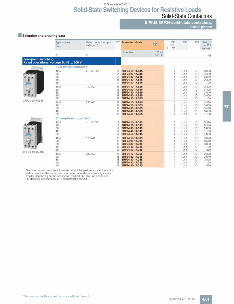
n Selection and ordering data
1) The type current provides information about the performance of the solid-state contactor. The actual permitted rated operational current Ie can be smaller depending on the connection method and start-up conditions. For derating see the manual, "Characteristic curves".
Type current1) Imax
Rated control supply voltage Us
DT Screw terminals PU(UNIT,
SET, M)
PS* PG Weightper PU
approx.
Order No. Priceper PUA V kg
Zero-point switching Rated operational voltage Ue 48 ... 600 V
3RF24 20-1AB45
Two-phase controlled
10.5 4 ... 30 DC A 3RF24 10-1AB45 1 1 unit 101 0.32020 A 3RF24 20-1AB45 1 1 unit 101 0.40030 A 3RF24 30-1AB45 1 1 unit 101 0.54040 B 3RF24 40-1AB45 1 1 unit 101 0.80050 A 3RF24 50-1AB45 1 1 unit 101 1.100
10.5 110 AC B 3RF24 10-1AB35 1 1 unit 101 0.32020 B 3RF24 20-1AB35 1 1 unit 101 0.40030 B 3RF24 30-1AB35 1 1 unit 101 0.54040 B 3RF24 40-1AB35 1 1 unit 101 0.80050 B 3RF24 50-1AB35 1 1 unit 101 1.100
10.5 230 AC B 3RF24 10-1AB55 1 1 unit 101 0.32020 B 3RF24 20-1AB55 1 1 unit 101 0.40030 B 3RF24 30-1AB55 1 1 unit 101 0.54040 B 3RF24 40-1AB55 1 1 unit 101 0.80050 B 3RF24 50-1AB55 1 1 unit 101 1.100
3RF24 10-1AC45
Three-phase controlled
10.5 4 ... 30 DC A 3RF24 10-1AC45 1 1 unit 101 0.32020 A 3RF24 20-1AC45 1 1 unit 101 0.54030 A 3RF24 30-1AC45 1 1 unit 101 0.80040 A 3RF24 40-1AC45 1 1 unit 101 1.10050 A 3RF24 50-1AC45 1 1 unit 101 1.850
10.5 110 AC B 3RF24 10-1AC35 1 1 unit 101 0.32020 B 3RF24 20-1AC35 1 1 unit 101 0.54030 B 3RF24 30-1AC35 1 1 unit 101 0.80040 B 3RF24 40-1AC35 1 1 unit 101 1.10050 B 3RF24 50-1AC35 1 1 unit 101 1.850
10.5 230 AC B 3RF24 10-1AC55 1 1 unit 101 0.32020 B 3RF24 20-1AC55 1 1 unit 101 0.54030 B 3RF24 30-1AC55 1 1 unit 101 0.80040 B 3RF24 40-1AC55 1 1 unit 101 1.10050 B 3RF24 50-1AC55 1 1 unit 101 1.850
Solid-State Switching Devices for Resistive LoadsSolid-State ContactorsSIRIUS 3RF24 solid-state contactors,three-phase
4/62 Siemens LV 1 · 2010* You can order this quantity or a multiple thereof.
4
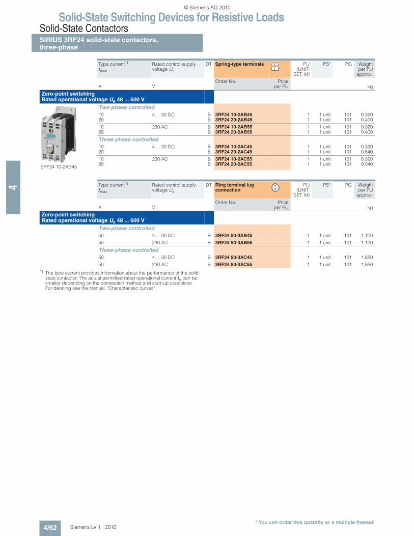
1) The type current provides information about the performance of the solid-state contactor. The actual permitted rated operational current Ie can be smaller depending on the connection method and start-up conditions. For derating see the manual, "Characteristic curves".
Type current1) Imax
Rated control supply voltage Us
DT Spring-type terminals PU(UNIT,
SET, M)
PS* PG Weightper PU
approx.
Order No. Priceper PUA V kg
Zero-point switching Rated operational voltage Ue 48 ... 600 V
3RF24 10-2AB45
Two-phase controlled
10 4 ... 30 DC B 3RF24 10-2AB45 1 1 unit 101 0.32020 B 3RF24 20-2AB45 1 1 unit 101 0.400
10 230 AC B 3RF24 10-2AB55 1 1 unit 101 0.32020 B 3RF24 20-2AB55 1 1 unit 101 0.400
Three-phase controlled
10 4 ... 30 DC B 3RF24 10-2AC45 1 1 unit 101 0.32020 B 3RF24 20-2AC45 1 1 unit 101 0.540
10 230 AC B 3RF24 10-2AC55 1 1 unit 101 0.32020 B 3RF24 20-2AC55 1 1 unit 101 0.540
Type current1) Imax
Rated control supply voltage Us
DT Ring terminal lug connection
PU(UNIT,
SET, M)
PS* PG Weightper PU
approx.
Order No. Priceper PUA V kg
Zero-point switching Rated operational voltage Ue 48 ... 600 V
Two-phase controlled
50 4 ... 30 DC B 3RF24 50-3AB45 1 1 unit 101 1.100
50 230 AC B 3RF24 50-3AB55 1 1 unit 101 1.100
Three-phase controlled
50 4 ... 30 DC B 3RF24 50-3AC45 1 1 unit 101 1.850
Solid-State Switching Devices for Resistive Loads3RF29 Function Modules
General data
4/63Siemens LV 1 · 2010
4
n Overview
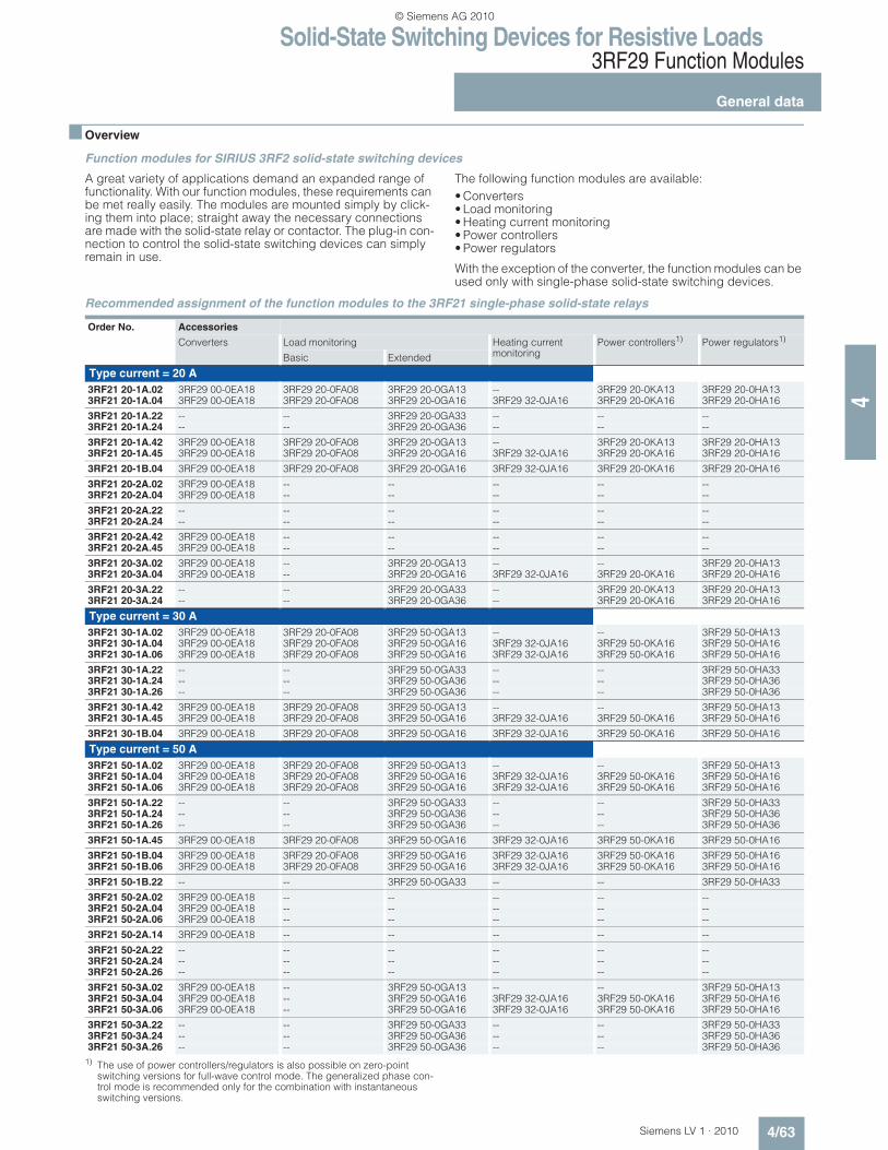
Function modules for SIRIUS 3RF2 solid-state switching devices
A great variety of applications demand an expanded range of functionality. With our function modules, these requirements can be met really easily. The modules are mounted simply by click-ing them into place; straight away the necessary connections are made with the solid-state relay or contactor. The plug-in con-nection to control the solid-state switching devices can simply remain in use.
The following function modules are available:
• Converters• Load monitoring• Heating current monitoring• Power controllers• Power regulators
With the exception of the converter, the function modules can be used only with single-phase solid-state switching devices.
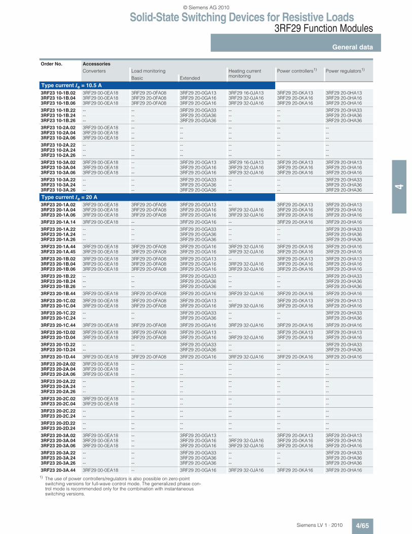
Recommended assignment of the function modules to the 3RF21 single-phase solid-state relays
1) The use of power controllers/regulators is also possible on zero-point switching versions for full-wave control mode. The generalized phase con-trol mode is recommended only for the combination with instantaneous switching versions.
Order No. Accessories
Converters Load monitoring Heating current monitoring
Solid-State Switching Devices for Resistive Loads3RF29 Function Modules
General data
4/64 Siemens LV 1 · 2010
4
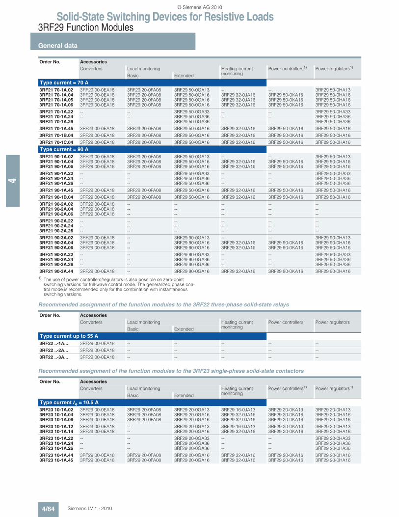
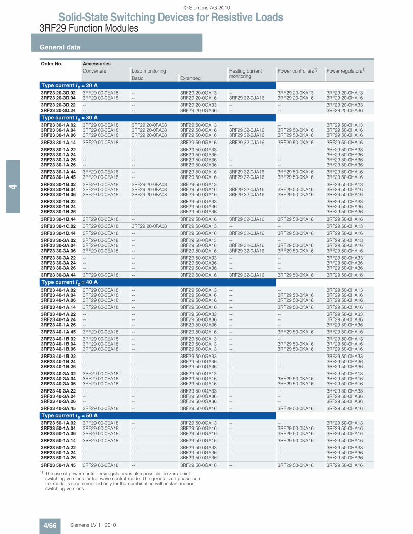
1) The use of power controllers/regulators is also possible on zero-point switching versions for full-wave control mode. The generalized phase con-trol mode is recommended only for the combination with instantaneous switching versions.
Recommended assignment of the function modules to the 3RF22 three-phase solid-state relays
Recommended assignment of the function modules to the 3RF23 single-phase solid-state contactors
Order No. Accessories
Converters Load monitoring Heating current monitoring
Solid-State Switching Devices for Resistive Loads3RF29 Function Modules
General data
4/65Siemens LV 1 · 2010
4
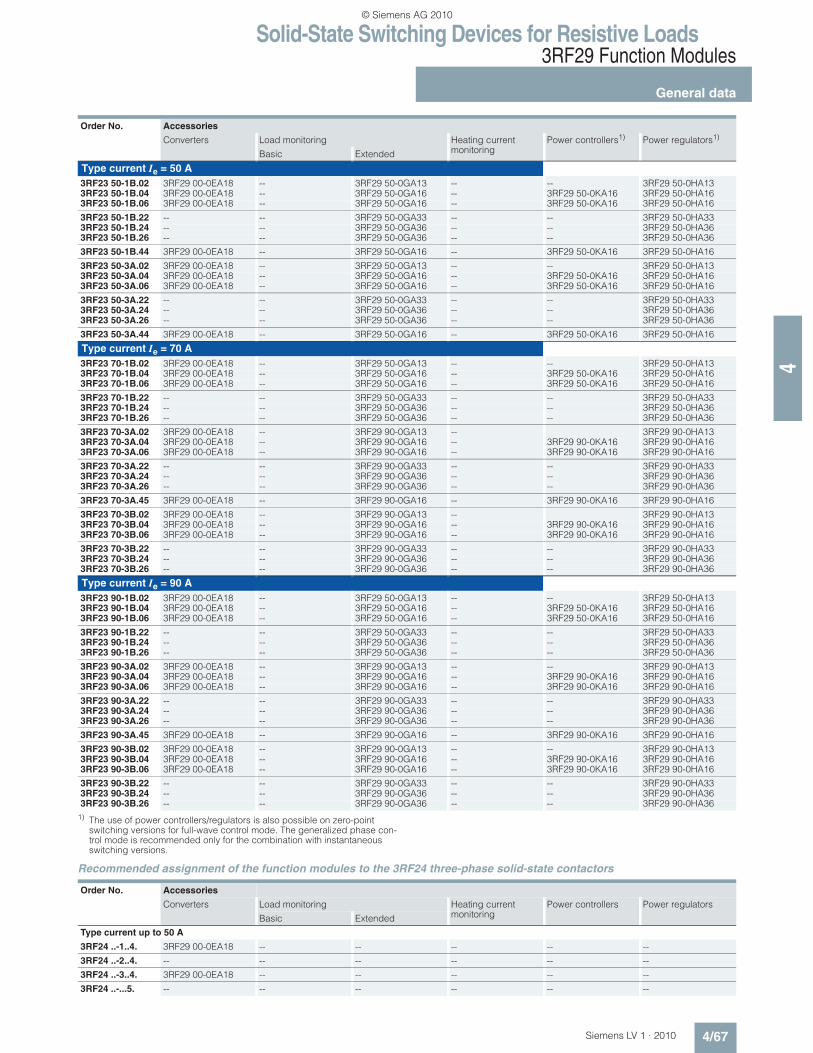
1) The use of power controllers/regulators is also possible on zero-point switching versions for full-wave control mode. The generalized phase con-trol mode is recommended only for the combination with instantaneous switching versions.
Order No. Accessories
Converters Load monitoring Heating current monitoring
Solid-State Switching Devices for Resistive Loads3RF29 Function Modules
General data
4/66 Siemens LV 1 · 2010
4
1) The use of power controllers/regulators is also possible on zero-point switching versions for full-wave control mode. The generalized phase con-trol mode is recommended only for the combination with instantaneous switching versions.
Order No. Accessories
Converters Load monitoring Heating current monitoring
Solid-State Switching Devices for Resistive Loads3RF29 Function Modules
General data
4/67Siemens LV 1 · 2010
41) The use of power controllers/regulators is also possible on zero-point
switching versions for full-wave control mode. The generalized phase con-trol mode is recommended only for the combination with instantaneous switching versions.
Recommended assignment of the function modules to the 3RF24 three-phase solid-state contactors
Order No. Accessories
Converters Load monitoring Heating current monitoring
Solid-State Switching Devices for Resistive Loads3RF29 Function Modules
SIRIUS converters for 3RF
4/68 Siemens LV 1 · 2010* You can order this quantity or a multiple thereof.
4
n Overview
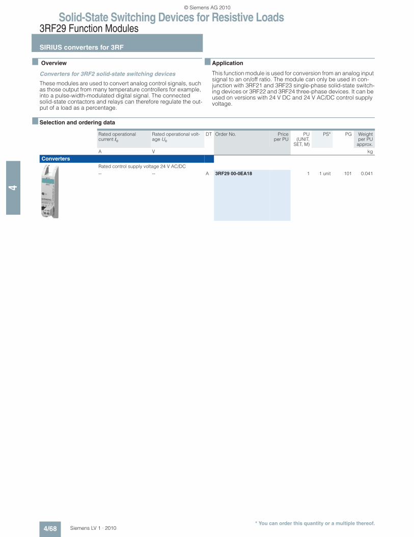
Converters for 3RF2 solid-state switching devices
These modules are used to convert analog control signals, such as those output from many temperature controllers for example, into a pulse-width-modulated digital signal. The connected solid-state contactors and relays can therefore regulate the out-put of a load as a percentage.
n Application
This function module is used for conversion from an analog input signal to an on/off ratio. The module can only be used in con-junction with 3RF21 and 3RF23 single-phase solid-state switch-ing devices or 3RF22 and 3RF24 three-phase devices. It can be used on versions with 24 V DC and 24 V AC/DC control supply voltage.
Solid-State Switching Devices for Resistive Loads3RF29 Function Modules
SIRIUS load monitoring for 3RF
4/69Siemens LV 1 · 2010* You can order this quantity or a multiple thereof.
4
n Overview
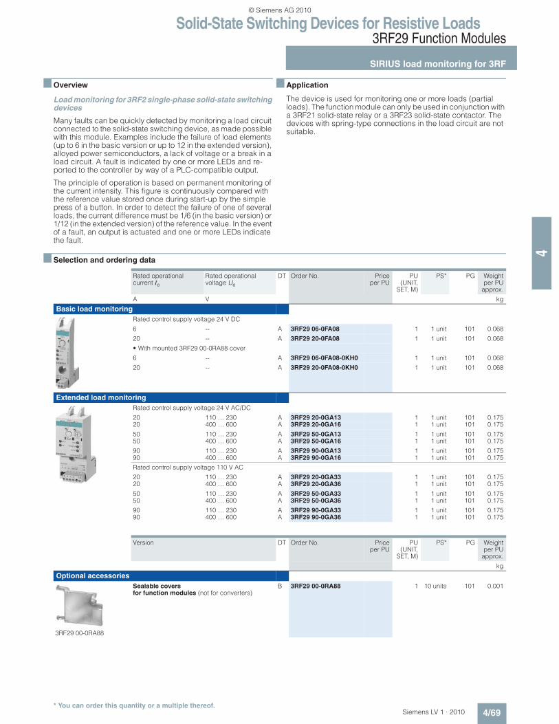
Load monitoring for 3RF2 single-phase solid-state switching devices
Many faults can be quickly detected by monitoring a load circuit connected to the solid-state switching device, as made possible with this module. Examples include the failure of load elements (up to 6 in the basic version or up to 12 in the extended version), alloyed power semiconductors, a lack of voltage or a break in a load circuit. A fault is indicated by one or more LEDs and re-ported to the controller by way of a PLC-compatible output.
The principle of operation is based on permanent monitoring of the current intensity. This figure is continuously compared with the reference value stored once during start-up by the simple press of a button. In order to detect the failure of one of several loads, the current difference must be 1/6 (in the basic version) or 1/12 (in the extended version) of the reference value. In the event of a fault, an output is actuated and one or more LEDs indicate the fault.
n Application
The device is used for monitoring one or more loads (partial loads). The function module can only be used in conjunction with a 3RF21 solid-state relay or a 3RF23 solid-state contactor. The devices with spring-type connections in the load circuit are not suitable.
n Selection and ordering data
Rated operational current Ie
Rated operational voltage Ue
DT Order No. Priceper PU
PU(UNIT,
SET, M)
PS* PG Weightper PU
approx.
A V kg
Basic load monitoring
Rated control supply voltage 24 V DC
6 -- A 3RF29 06-0FA08 1 1 unit 101 0.068
20 -- A 3RF29 20-0FA08 1 1 unit 101 0.068
• With mounted 3RF29 00-0RA88 cover
6 -- A 3RF29 06-0FA08-0KH0 1 1 unit 101 0.068
20 -- A 3RF29 20-0FA08-0KH0 1 1 unit 101 0.068
Extended load monitoring
Rated control supply voltage 24 V AC/DC
20 110 … 230 A 3RF29 20-0GA13 1 1 unit 101 0.17520 400 … 600 A 3RF29 20-0GA16 1 1 unit 101 0.175
50 110 … 230 A 3RF29 50-0GA13 1 1 unit 101 0.17550 400 … 600 A 3RF29 50-0GA16 1 1 unit 101 0.175
90 110 … 230 A 3RF29 90-0GA13 1 1 unit 101 0.17590 400 … 600 A 3RF29 90-0GA16 1 1 unit 101 0.175
Rated control supply voltage 110 V AC
20 110 … 230 A 3RF29 20-0GA33 1 1 unit 101 0.17520 400 … 600 A 3RF29 20-0GA36 1 1 unit 101 0.175
50 110 … 230 A 3RF29 50-0GA33 1 1 unit 101 0.17550 400 … 600 A 3RF29 50-0GA36 1 1 unit 101 0.175
90 110 … 230 A 3RF29 90-0GA33 1 1 unit 101 0.17590 400 … 600 A 3RF29 90-0GA36 1 1 unit 101 0.175
Version DT Order No. Priceper PU
PU(UNIT,
SET, M)
PS* PG Weightper PU
approx.
kg
Optional accessories
3RF29 00-0RA88
Sealable covers for function modules (not for converters)
Solid-State Switching Devices for Resistive Loads3RF29 Function Modules
SIRIUS heating current monitoring for 3RF
4/70 Siemens LV 1 · 2010* You can order this quantity or a multiple thereof.
4
n Overview
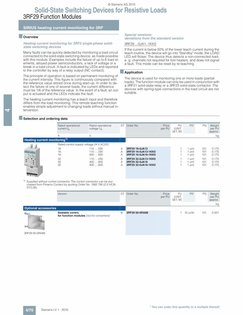
Heating current monitoring for 3RF2 single-phase solid-state switching devices
Many faults can be quickly detected by monitoring a load circuit connected to the solid-state switching device, as made possible with this module. Examples include the failure of up to 6 load el-ements, alloyed power semiconductors, a lack of voltage or a break in a load circuit. A fault is indicated by LEDs and reported to the controller by way of a relay output (NC contact).
The principle of operation is based on permanent monitoring of the current intensity. This figure is continuously compared with the reference value stored once during start-up. In order to de-tect the failure of one of several loads, the current difference must be 1/6 of the reference value. In the event of a fault, an out-put is actuated and the LEDs indicate the fault.
The heating current monitoring has a teach input and therefore differs from the load monitoring. This remote teaching function enables simple adjustment to changing loads without manual in-tervention.
Special versions: deviations from the standard version
3RF29 ..-0JA1.-1KK0
If the current is below 50% of the lower teach current during the teach routine, the device will go into "Standby" mode; the LOAD LED will flicker. The device thus detects a non-connected load, e. g. channels not required for tool heaters, and does not signal a fault. This mode can be reset by re-teaching.
n Application
The device is used for monitoring one or more loads (partial loads). The function module can only be used in conjunction with a 3RF21 solid-state relay or a 3RF23 solid-state contactor. The devices with spring-type connections in the load circuit are not suitable.
n Selection and ordering data
1) Supplied without control connector. The control connector can be pur-chased from Phoenix Contact by quoting Order No. 1982 790 (2.5 HC/6-ST-5.08).
Rated operational current Ie
Rated operational voltage Ue
DT Order No. Priceper PU
PU(UNIT,
SET, M)
PS* PG Weightper PU
approx.
A V kg
Heating current monitoring1)
Rated control supply voltage 24 V AC/DC
16 110 … 230 A 3RF29 16-0JA13 1 1 unit 101 0.17516 110 … 230 A 3RF29 16-0JA13-1KK0 1 1 unit 101 0.17516 400 … 600 A 3RF29 16-0JA16-1KK0 1 1 unit 101 0.175
32 110 … 230 A 3RF29 32-0JA13-1KK0 1 1 unit 101 0.17532 400 … 600 A 3RF29 32-0JA16 1 1 unit 101 0.17532 400 … 600 A 3RF29 32-0JA16-1KK0 1 1 unit 101 0.175
Version DT Order No. Priceper PU
PU(UNIT,
SET, M)
PS* PG Weightper PU
approx.
kg
Optional accessories
3RF29 00-0RA88
Sealable covers for function modules (not for converters)
Solid-State Switching Devices for Resistive Loads3RF29 Function Modules
SIRIUS power controllers for 3RF
4/71Siemens LV 1 · 2010* You can order this quantity or a multiple thereof.
4
n Overview
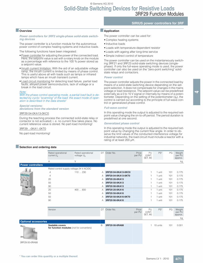
Power controllers for 3RF2 single-phase solid-state switch-ing devices
The power controller is a function module for the autonomous power control of complex heating systems and inductive loads.
The following functions have been integrated:
• Power controller for adjusting the power of the connected load. Here, the setpoint value is set with a rotary knob on the module as a percentage with reference to the 100 % power stored as a setpoint value.
• Inrush current limitation: With the aid of an adjustable voltage ramp, the inrush current is limited by means of phase control. This is useful above all with loads such as lamps or infrared lamps which have an inrush transient current.
• Load circuit monitoring for detecting load failure, partial load faults, alloyed power semiconductors, lack of voltage or a break in the load circuit.
Note:With the phase control operating mode, a partial load fault is de-tected by cyclic "scanning" of the load; the exact mode of oper-ation is described in the data sheets!
Special versions: deviations from the standard version
3RF29 04-0KA13-0KC0
During the teaching process the connected solid-state relay or contactor is not activated; i. e. no current flow takes place. No current reference value is stored. No part-load monitoring!
3RF29 ..-0KA1.-0KT0
No part-load monitoring!
n Application
The power controller can be used for:
• Complex heating systems
• Inductive loads
• Loads with temperature-dependent resistor
• Loads with ageing after long-time service
• Simple indirect control of temperature
The power controller can be used on the instantaneously switch-ing 3RF21 and 3RF23 solid-state switching devices (single-phase). If only the full-wave operating mode is used, the power controller can also be used on the "zero-point switching" solid-state relays and contactors.
Power control
The power controller adjusts the power in the connected load by means of a solid-state switching device depending on the set-point selection. It does not compensate for changes in the mains voltage or load resistance. The setpoint value can be predefined externally as a 0 to 10 V signal or internally by means of a poten-tiometer. Depending on the setting of the potentiometer (tR), the control is carried out according to the principle of full-wave con-trol or generalized phase control.
Full-wave control
In this operating mode the output is adjusted to the required set-point value changing the on-to-off period. The period duration is predefined at one second.
Generalized phase control
In this operating mode the output is adjusted to the required set-point value by changing the current flow angle. In order to ob-serve the limit values of the conducted interference voltage for industrial networks, the load circuit must include a reactor with a rating of at least 200 µH.
n Selection and ordering data
Rated operational current Ie
Rated operational voltage Ue
DT Order No. Priceper PU
PU(UNIT,
SET, M)
PS* PG Weightper PU
approx.
A V kg
Power controllers
Rated control supply voltage 24 V AC/DC
4 110 … 230 A 3RF29 04-0KA13-0KC0 1 1 unit 101 0.175
4 A 3RF29 04-0KA13-0KT0 1 1 unit 101 0.175
20 A 3RF29 20-0KA13 1 1 unit 101 0.175
50 A 3RF29 50-0KA13 1 1 unit 101 0.175
90 A 3RF29 90-0KA13 1 1 unit 101 0.175
20 400 … 600 A 3RF29 20-0KA16 1 1 unit 101 0.175
50 A 3RF29 50-0KA16 1 1 unit 101 0.175
50 A 3RF29 50-0KA16-0KT0 1 1 unit 101 0.175
90 A 3RF29 90-0KA16 1 1 unit 101 0.175
Version DT Order No. Priceper PU
PU(UNIT,
SET, M)
PS* PG Weightper PU
approx.
kg
Optional accessories
3RF29 00-0RA88
Sealable covers for function modules (not for converters)
Solid-State Switching Devices for Resistive Loads3RF29 Function Modules
SIRIUS power regulators for 3RF
4/72 Siemens LV 1 · 2010* You can order this quantity or a multiple thereof.
4
n Overview
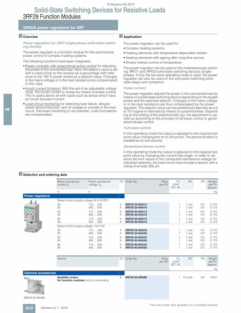
Power regulators for 3RF2 single-phase solid-state switch-ing devices
The power regulator is a function module for the autonomous power control of complex heating systems.
The following functions have been integrated:
• Power controller with proportional-action control for adjusting the power of the connected load. Here, the setpoint value is set with a rotary knob on the module as a percentage with refer-ence to the 100 % power stored as a setpoint value. Changes in the mains voltage or in the load resistance are compensated in this case.
• Inrush current limitation: With the aid of an adjustable voltage ramp, the inrush current is limited by means of phase control. This is useful above all with loads such as lamps which have an inrush transient current.
• Load circuit monitoring for detecting load failure, alloyed power semiconductors, lack of voltage or a break in the load circuit. Part-load monitoring is not possible. Load fluctuations are compensated.
n Application
The power regulator can be used for:
• Complex heating systems
• Heating elements with temperature-dependent resistor
• Heating elements with ageing after long-time service
• Simple indirect control of temperature
The power regulator can be used on the instantaneously switch-ing 3RF21 and 3RF23 solid-state switching devices (single-phase). If only the full-wave operating mode is used, the power regulator can also be used on the zero-point switching solid-state relays and contactors.
Power control
The power regulator adjusts the power in the connected load by means of a solid-state switching device depending on the taught power and the selected setpoint. Changes in the mains voltage or in the load resistance are thus compensated by the power regulator. The setpoint value can be predefined externally as a 0 to 10 V signal or internally by means of a potentiometer. Depend-ing on the setting of the potentiometer (tR), the adjustment is car-ried out according to the principle of full-wave control or gener-alized phase control.
Full-wave control
In this operating mode the output is adjusted to the required set-point value changing the on-to-off period. The period duration is predefined at one second.
Generalized phase control
In this operating mode the output is adjusted to the required set-point value by changing the current flow angle. In order to ob-serve the limit values of the conducted interference voltage for industrial networks, the load circuit must include a reactor with a rating of at least 200 µH.
n Selection and ordering data
Rated operational current Ie
Rated operational voltage Ue
DT Order No. Priceper PU
PU(UNIT,
SET, M)
PS* PG Weightper PU
approx.
A V kg
Power regulators
Rated control supply voltage 24 V AC/DC
20 110 … 230 A 3RF29 20-0HA13 1 1 unit 101 0.17520 400 … 600 A 3RF29 20-0HA16 1 1 unit 101 0.175
50 110 … 230 A 3RF29 50-0HA13 1 1 unit 101 0.17550 400 … 600 A 3RF29 50-0HA16 1 1 unit 101 0.175
90 110 … 230 A 3RF29 90-0HA13 1 1 unit 101 0.17590 400 … 600 A 3RF29 90-0HA16 1 1 unit 101 0.175
Rated control supply voltage 110 V AC
20 110 … 230 A 3RF29 20-0HA33 1 1 unit 101 0.17520 400 … 600 A 3RF29 20-0HA36 1 1 unit 101 0.175
50 110 … 230 A 3RF29 50-0HA33 1 1 unit 101 0.17550 400 … 600 A 3RF29 50-0HA36 1 1 unit 101 0.175
90 110 … 230 A 3RF29 90-0HA33 1 1 unit 101 0.17590 400 … 600 A 3RF29 90-0HA36 1 1 unit 101 0.175
Version DT Order No. Priceper PU
PU(UNIT,
SET, M)
PS* PG Weightper PU
approx.
kg
Optional accessories
3RF29 00-0RA88
Sealable covers for function modules (not for converters)
Solid-State Switching Devices for Switching MotorsSolid-State Contactors
General data
4/73Siemens LV 1 · 2010
4
n Overview
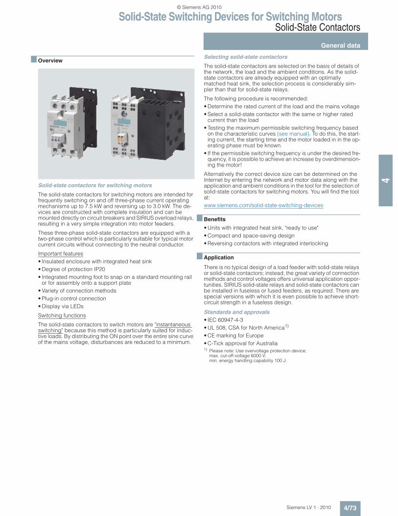
Solid-state contactors for switching motors
The solid-state contactors for switching motors are intended for frequently switching on and off three-phase current operating mechanisms up to 7.5 kW and reversing up to 3.0 kW. The de-vices are constructed with complete insulation and can be mounted directly on circuit breakers and SIRIUS overload relays, resulting in a very simple integration into motor feeders.
These three-phase solid-state contactors are equipped with a two-phase control which is particularly suitable for typical motor current circuits without connecting to the neutral conductor.
Important features
• Insulated enclosure with integrated heat sink
• Degree of protection IP20
• Integrated mounting foot to snap on a standard mounting rail or for assembly onto a support plate
• Variety of connection methods
• Plug-in control connection
• Display via LEDs
Switching functions
The solid-state contactors to switch motors are "instantaneous switching" because this method is particularly suited for induc-tive loads. By distributing the ON point over the entire sine curve of the mains voltage, disturbances are reduced to a minimum.
Selecting solid-state contactors
The solid-state contactors are selected on the basis of details of the network, the load and the ambient conditions. As the solid-state contactors are already equipped with an optimally matched heat sink, the selection process is considerably sim-pler than that for solid-state relays.
The following procedure is recommended:
• Determine the rated current of the load and the mains voltage
• Select a solid-state contactor with the same or higher rated current than the load
• Testing the maximum permissible switching frequency based on the characteristic curves (see manual). To do this, the start-ing current, the starting time and the motor loaded in in the op-erating phase must be known.
• If the permissible switching frequency is under the desired fre-quency, it is possible to achieve an increase by overdimension-ing the motor!
Alternatively the correct device size can be determined on the Internet by entering the network and motor data along with the application and ambient conditions in the tool for the selection of solid-state contactors for switching motors. You will find the tool at:
www.siemens.com/solid-state-switching-devices
n Benefits
• Units with integrated heat sink, "ready to use"
• Compact and space-saving design
• Reversing contactors with integrated interlocking
n Application
There is no typical design of a load feeder with solid-state relays or solid-state contactors; instead, the great variety of connection methods and control voltages offers universal application oppor-tunities. SIRIUS solid-state relays and solid-state contactors can be installed in fuseless or fused feeders, as required. There are special versions with which it is even possible to achieve short-circuit strength in a fuseless design.
Standards and approvals
• IEC 60947-4-3
• UL 508, CSA for North America1)
• CE marking for Europe
• C-Tick approval for Australia1) Please note: Use overvoltage protection device;
max. cut-off-voltage 6000 V; min. energy handling capability 100 J.
Solid-State Switching Devices for Switching MotorsSolid-State Contactors
General data
4/74 Siemens LV 1 · 2010
4
n More information
Connection methods
You can choose between the following connection methods for the solid-state contactors for switching motors:
Screw connection
The screw connection system is the standard among industrial controls. Open terminals and a plus-minus screw are just two features of this technology. Two conductors of up to 6 mm² can be connected in just one terminal. As a result, loads of up to 50 A can be connected.
Spring-type terminal connection system
This innovative technology manages without any screw connec-tion. This means that very high vibration resistance is achieved. Two conductors of up to 2.5 mm² can be connected to each ter-minal. As a result, loads of up to 20 A can be dealt with.
Short-circuit protection
Despite the rugged power semiconductors that are used, solid-state switching devices respond more sensitively to short-cir-cuits in the load feeder. Consequently, special precautions have to be taken against destruction, depending on the type of de-sign.
Siemens generally recommends using SITOR semiconductor fuses. These fuses also provide protection against destruction in the event of a short-circuit even when the solid-state contactors and solid-state relays are fully utilized.
Alternatively, if there is lower loading, protection can also be pro-vided by standard fuses or miniature circuit breakers. This pro-tection is achieved by overdimensioning the solid-state switch-ing devices accordingly.
Specification
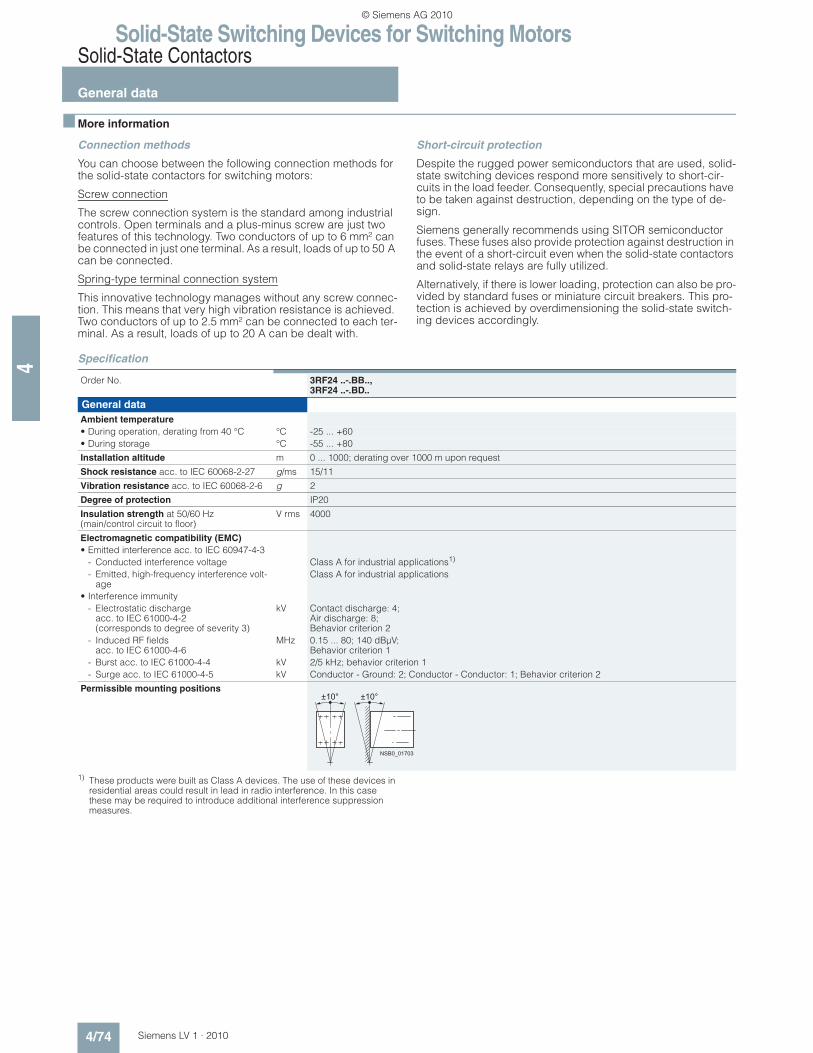
1) These products were built as Class A devices. The use of these devices in residential areas could result in lead in radio interference. In this case these may be required to introduce additional interference suppression measures.
Order No. 3RF24 ..-.BB.., 3RF24 ..-.BD..
General data
Ambient temperature
• During operation, derating from 40 °C °C -25 ... +60
• During storage °C -55 ... +80
Installation altitude m 0 ... 1000; derating over 1000 m upon request
Shock resistance acc. to IEC 60068-2-27 g/ms 15/11
Vibration resistance acc. to IEC 60068-2-6 g 2
Degree of protection IP20
Insulation strength at 50/60 Hz (main/control circuit to floor)
V rms 4000
Electromagnetic compatibility (EMC)
• Emitted interference acc. to IEC 60947-4-3
- Conducted interference voltage Class A for industrial applications1)
- Emitted, high-frequency interference volt-age
Class A for industrial applications
• Interference immunity
- Electrostatic discharge acc. to IEC 61000-4-2 (corresponds to degree of severity 3)
kV Contact discharge: 4; Air discharge: 8; Behavior criterion 2
Solid-State Switching Devices for Switching MotorsSolid-State Contactors
General data
4/75Siemens LV 1 · 2010
4
Notes on integration in the load feeders
The SIRIUS solid-state switching devices are very easy to inte-grate into the load feeders thanks to their industrial connection method and design.
Particular attention must however be paid to the circumstances of the installation and ambient conditions, as the performance of the solid-state switching devices is largely dependent on these. Depending on the version, certain restrictions must be ob-served. Detailed information, for example in relation to solid-state contactors about the minimum spacing and to solid-state relays about the choice of heat sink, is given in the technical specifications (see manual) and the product data sheets.
For applications with a very large power requirement it is possi-ble to use SIVOLT AC power controller. More information on the product range can be found in the Catalog DA 68 or in our Mall.
Despite the rugged power semiconductors that are used, solid-state switching devices respond more sensitively to short-cir-cuits in the load feeder. Consequently, special precautions have to be taken against destruction, depending on the type of de-sign.
Siemens generally recommends using SITOR semiconductor protection fuses. These fuses also provide protection against destruction in the event of a short-circuit even when the solid-state contactors and solid-state relays are fully utilized.
Alternatively, if there is lower loading, protection can also be pro-vided by standard fuses or miniature circuit breakers. This pro-tection is achieved by overdimensioning the solid-state switch-ing devices accordingly. The technical specifications and the product data sheets contain details both about the solid-state fuse protection itself and about use of the devices with conven-tional protection equipment.
Semiconductor motor and reversing contactors can be easily combined with the 3RV motor starter protectors and 3RB2 over-load relay from the SIRIUS modular system. Thus, fuseless and fuse motor feeders can be designed easily and in a space-sav-ing manner.
Electromagnetic compatibility (EMC)
The solid-state switching devices are suitable for interference-free operation in industrial networks without further measures. If they are used in public networks, it may be necessary for con-ducted interference to be reduced by means of filters.
Suitable filters can be ordered from EPCOS AG. You can find more information on the Internet at:
Solid-State Switching Devices for Switching MotorsSolid-State ContactorsSIRIUS 3RF24 solid-state contactors,three-phase
4/76 Siemens LV 1 · 2010* You can order this quantity or a multiple thereof.
4
n Overview
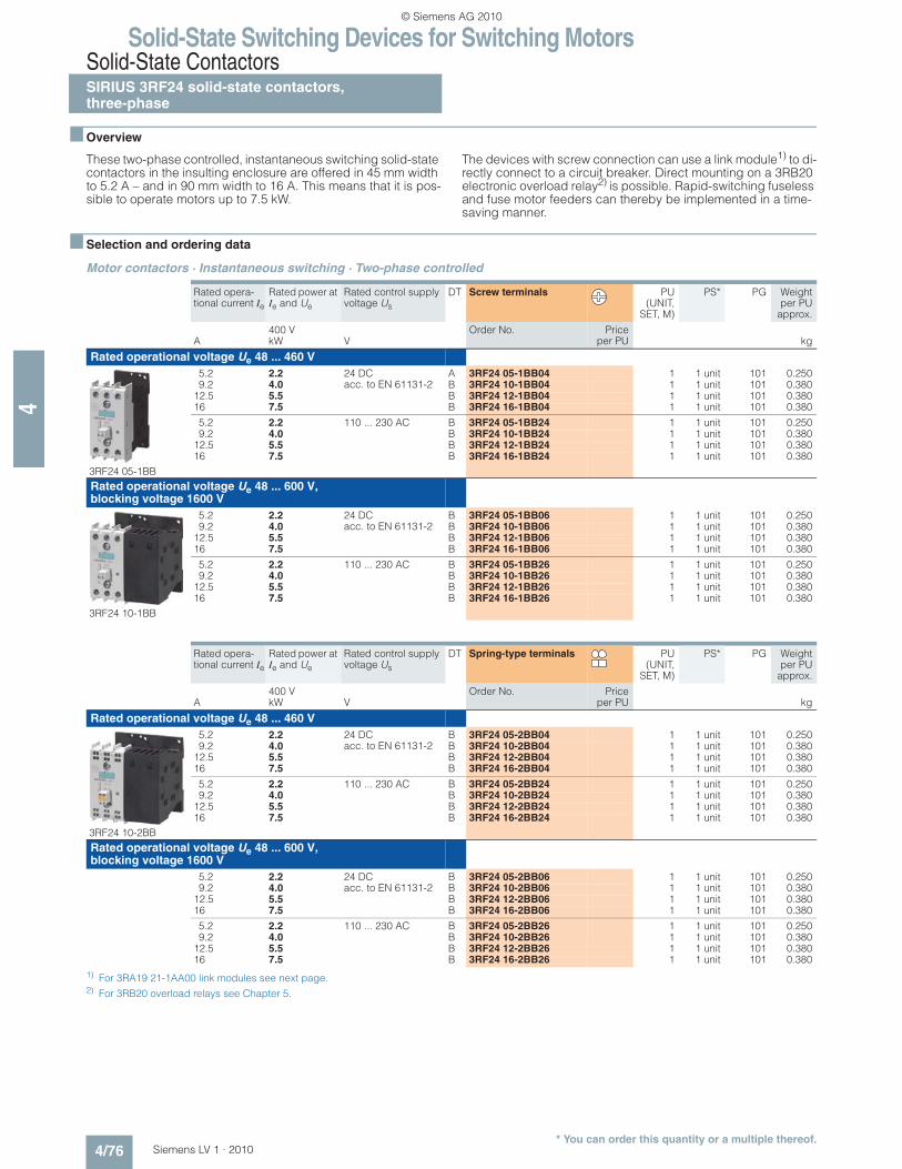
These two-phase controlled, instantaneous switching solid-state contactors in the insulting enclosure are offered in 45 mm width to 5.2 A – and in 90 mm width to 16 A. This means that it is pos-sible to operate motors up to 7.5 kW.
The devices with screw connection can use a link module1) to di-rectly connect to a circuit breaker. Direct mounting on a 3RB20 electronic overload relay2) is possible. Rapid-switching fuseless and fuse motor feeders can thereby be implemented in a time-saving manner.
n Selection and ordering data
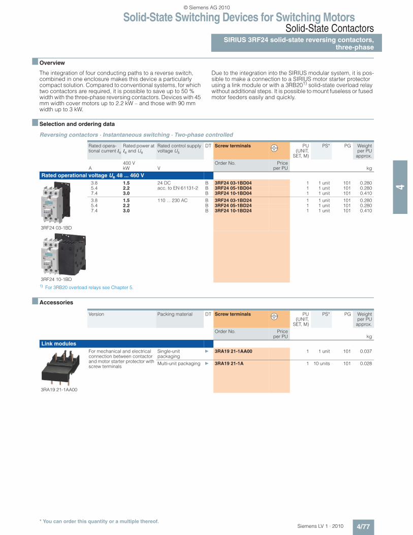
Motor contactors · Instantaneous switching · Two-phase controlled
1) For 3RA19 21-1AA00 link modules see next page.2) For 3RB20 overload relays see Chapter 5.
Rated opera-tional current Ie
Rated power at Ie and Ue
Rated control supply voltage Us
DT Screw terminals PU(UNIT,
SET, M)
PS* PG Weightper PU
approx.
400 V Order No. Priceper PUA kW V kg
Rated operational voltage Ue 48 ... 460 V
3RF24 05-1BB
5.2 2.2 24 DC acc. to EN 61131-2
A 3RF24 05-1BB04 1 1 unit 101 0.2509.2 4.0 B 3RF24 10-1BB04 1 1 unit 101 0.380
12.5 5.5 B 3RF24 12-1BB04 1 1 unit 101 0.38016 7.5 B 3RF24 16-1BB04 1 1 unit 101 0.380
5.2 2.2 110 ... 230 AC B 3RF24 05-1BB24 1 1 unit 101 0.2509.2 4.0 B 3RF24 10-1BB24 1 1 unit 101 0.380
12.5 5.5 B 3RF24 12-1BB24 1 1 unit 101 0.38016 7.5 B 3RF24 16-1BB24 1 1 unit 101 0.380
Rated operational voltage Ue 48 ... 600 V, blocking voltage 1600 V
3RF24 10-1BB
5.2 2.2 24 DC acc. to EN 61131-2
B 3RF24 05-1BB06 1 1 unit 101 0.2509.2 4.0 B 3RF24 10-1BB06 1 1 unit 101 0.380
12.5 5.5 B 3RF24 12-1BB06 1 1 unit 101 0.38016 7.5 B 3RF24 16-1BB06 1 1 unit 101 0.380
5.2 2.2 110 ... 230 AC B 3RF24 05-1BB26 1 1 unit 101 0.2509.2 4.0 B 3RF24 10-1BB26 1 1 unit 101 0.380
12.5 5.5 B 3RF24 12-1BB26 1 1 unit 101 0.38016 7.5 B 3RF24 16-1BB26 1 1 unit 101 0.380
Rated opera-tional current Ie
Rated power at Ie and Ue
Rated control supply voltage Us
DT Spring-type terminals PU(UNIT,
SET, M)
PS* PG Weightper PU
approx.
400 V Order No. Priceper PUA kW V kg
Rated operational voltage Ue 48 ... 460 V
3RF24 10-2BB
5.2 2.2 24 DC acc. to EN 61131-2
B 3RF24 05-2BB04 1 1 unit 101 0.2509.2 4.0 B 3RF24 10-2BB04 1 1 unit 101 0.380
12.5 5.5 B 3RF24 12-2BB04 1 1 unit 101 0.38016 7.5 B 3RF24 16-2BB04 1 1 unit 101 0.380
5.2 2.2 110 ... 230 AC B 3RF24 05-2BB24 1 1 unit 101 0.2509.2 4.0 B 3RF24 10-2BB24 1 1 unit 101 0.380
12.5 5.5 B 3RF24 12-2BB24 1 1 unit 101 0.38016 7.5 B 3RF24 16-2BB24 1 1 unit 101 0.380
Rated operational voltage Ue 48 ... 600 V, blocking voltage 1600 V
5.2 2.2 24 DC acc. to EN 61131-2
B 3RF24 05-2BB06 1 1 unit 101 0.2509.2 4.0 B 3RF24 10-2BB06 1 1 unit 101 0.380
12.5 5.5 B 3RF24 12-2BB06 1 1 unit 101 0.38016 7.5 B 3RF24 16-2BB06 1 1 unit 101 0.380
5.2 2.2 110 ... 230 AC B 3RF24 05-2BB26 1 1 unit 101 0.2509.2 4.0 B 3RF24 10-2BB26 1 1 unit 101 0.380
12.5 5.5 B 3RF24 12-2BB26 1 1 unit 101 0.38016 7.5 B 3RF24 16-2BB26 1 1 unit 101 0.380
4/77Siemens LV 1 · 2010* You can order this quantity or a multiple thereof.
4
n Overview
The integration of four conducting paths to a reverse switch, combined in one enclosure makes this device a particularly compact solution. Compared to conventional systems, for which two contactors are required, it is possible to save up to 50 % width with the three-phase reversing contactors. Devices with 45 mm width cover motors up to 2.2 kW – and those with 90 mm width up to 3 kW.
Due to the integration into the SIRIUS modular system, it is pos-sible to make a connection to a SIRIUS motor starter protector using a link module or with a 3RB201) solid-state overload relay without additional steps. It is possible to mount fuseless or fused motor feeders easily and quickly.