168
SOLUTIONS IN PLASTICS CUSTOM FINISHED PRODUCTS | SEMI-FINISHED PRODUCTS | CHAIN GUIDES | CHAIN TENSIONERS smooth. good. advised. www.murtfeldt.com

SOLU
TIO
NS
IN P
LAST
ICS
SOLUTIONS IN PLASTICSCUSTOM FINISHED PRODUCTS | SEMI-FINISHED PRODUCTS | CHAIN GUIDES | CHAIN TENSIONERS
smooth. good. advised.
ww
w.m
urtf
eldt
.com
ww
w.m
urtf
eldt
.com
D/0
713/
3720
1104
7-E-
2.50
0
Heßlingsweg 14 – 16D-44309 DortmundPhone +49 231 20609-0Fax +49 231 2060992www.murtfeldt.com

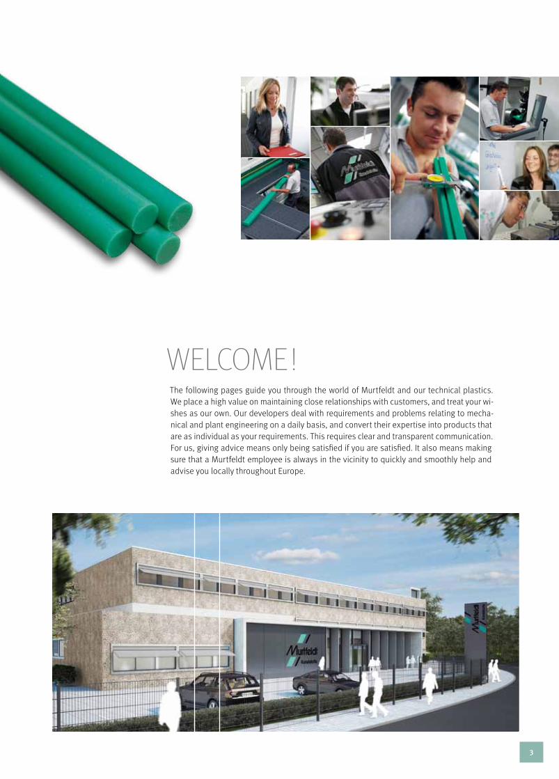
The following pages guide you through the world of Murtfeldt and our technical plastics. We place a high value on maintaining close relationships with customers, and treat your wi-shes as our own. Our developers deal with requirements and problems relating to mecha-nical and plant engineering on a daily basis, and convert their expertise into products that are as individual as your requirements. This requires clear and transparent communication. For us, giving advice means only being satisfied if you are satisfied. It also means making sure that a Murtfeldt employee is always in the vicinity to quickly and smoothly help and advise you locally throughout Europe.
welcome !
3

cOnTEnT
1
3
4
5
6
2
Plastics
chain, belt and sliding guides
tensioning systems
Technical informaTion
individual solutions
murtfeldt – the comPany Murtfeldt – 15 good reasons :: Murtfeldt has many faces :: Local to you – across Europe
General :: Food safe [FS] plastics :: Technical plastics :: High-performance plastics
General :: chain guides :: Belt guides :: chain racks :: Special profiles :: Accessories
chain tensioners :: Belt tensioners
Jointly designed :: Murtfeldt machinery :: Plastic conveyor screws :: Product turners :: Design questionnaire :: Quality management
Sheet dimensions :: Rod dimensions :: Plastic characteristics :: Plastics compared :: Information on the behaviour of plastics
DEUTSCHLAND
POLEN
GROSSBRITANNIEN
FRANKREICH
SPANIEN
ITALIEN
SCHWEIZ
TSCHECHIEN
SLOWAK. REP.
UNGARN
GRIECHEN- LAND
BULGARIEN
FINNLAND
SCHWEDEN
NORWEGEN
DÄNE-MARK
NIEDER-LANDE
BELGIEN
TÜRKEI
PORTUGAL
LITAUEN
RUMÄNIEN
IRLAND
RUSSLAND
Kopenhagen
Warschau
Berlin
Paris
Madrid
London
Prag
Wien
Bratislava
Budapest
Bern
Rom
Amsterdam
Brüssel
Sofia
Athen
Oslo
Stockholm
Helsinki
Szolnok
Törökbalint
Povazska Bystrica
MiddlesexNoord- wijkerhout
Ølstykke Malmö
Vantaa
Lodz
Vedano Olona
Aubervilliers Cedex
Sant Julia de Ramis
Ruse
Piraeus
Istanbul
Ankara
KaunasVilnius
Bukarest
Dublin
Moskau
Lissabon
ÖSTERREICH
15 – 24
143 – 166
107 – 142
57 – 106
25 – 56
5 – 14
4

the company
5

More than 50 years of experience,
growth, and innovation The highest quality standards and
optimum quality management A consolidated, area-wide national
network of advisers Representatives throughout
Europe and the world Consulting services and project
supervision in technical appli-cation and design
All consulting services are free and
non-binding and are provided by permanent points of contact in Germany and worldwide Quick and flexible delivery of
standard parts – within 24 hours on request Custom manufacturing from
drawings The most up-to-date CAD
applications
Help with material selection
Material analysis and development
in Murtfeldt’s own laboratories Smooth multi-shift production
Short response and reaction times
The status of orders can be queried
at any time, thus providing maxi-mum transparency
Environmentally aware thinking
and trade
MurTFELDT – 15 GOOD rEASOnS
6

Development and production of plastic semi-finished products
Technical Office / Work Scheduling
Other administration
Programming
Spann-Box® manufacturing
Deburring
MurTFELDT hAS MAny FAcES
Mu
rtf
eld
t –
the
coM
pan
y
7

Quality Assurance
Profiles and Cutting 2
Internal Sales Key AccountSweepers
Export Sales
Industrial apprentices
8

Internal Sales North
Calculation
Workshop ManagersInternal Sales
AccountingGardeners
Mu
rtf
eld
t –
the
coM
pan
y
9
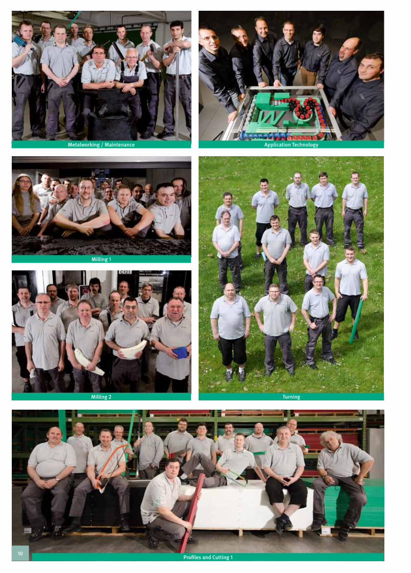
Profiles and Cutting 1
TurningMilling 2
Milling 1
Metalworking / Maintenance Application Technology
10

Field Sales
IT departmentInternal Sales South 2
Milling 3Kitchen
Internal Sales South 1
Purchasing departmentDispatch Department
Mu
rtf
eld
t –
the
coM
pan
y
11

LOcAL rEPrESEnTATIVES …
for the contact details of our representatives, go to www.murtfeldt.com.
Saarbrücken
Stuttgart
Mainz
Düsseldorf
LOWER SAXONY
BREMEN
MECKLENBURG-WESTERN POMERANIA
SCHLESWIG-HOLSTEIN
BRANDENBURG
BERLIN
NORTH RHINE WESTPHALIA
THURINGIASAXONY
BAVARIA
BADEN-WÜRTTEMBERG
RHEINLAND-PFALZ
SAARLAND
SAXONY ANHALT
HESSEN
Berlin
HAMBURG
Kiel
Schwerin
Hanover
Bremen
Hamburg
Potsdam
Munich
Dresden Erfurt
Magdeburg
Wiesbaden
12
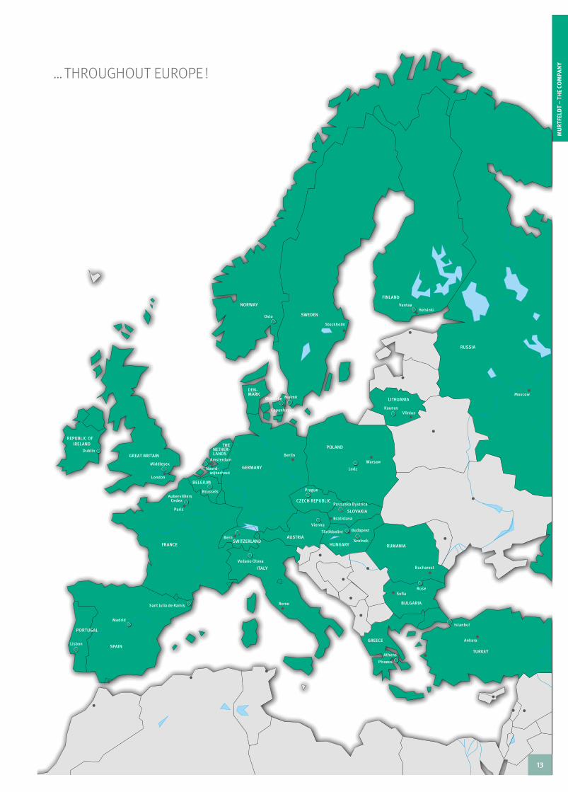
… ThrOuGhOuT EurOPE !
Mu
rtf
eld
t –
the
coM
pan
y
GERMANY
POLAND
GREAT BRITAIN
FRANCE
SPAIN
ITALY
SWITZERLAND
CZECH REPUBLIC
SLOVAKIA
HUNGARY
GREECE
BULGARIA
FINLAND
SWEDEN
NORWAY
DEN-MARK
NETHER-THE
LANDS
BELGIUM
TURKEY
PORTUGAL
LITHUANIA
RUMANIA
IRELANDREPUBLIC OF
RUSSIA
Copenhagen
Warsaw
Berlin
Paris
Madrid
London
Prague
Vienna
Bratislava
Budapest
Bern
Rome
Amsterdam
Brussels
Sofia
Athens
Oslo
Stockholm
Helsinki
Szolnok
Törökbalint
Povazska Bystrica
Middlesex Noord- wijkerhout
Ølstykke Malmö
Vantaa
Lodz
Vedano Olona
Aubervilliers Cedex
Sant Julia de Ramis
Ruse
Piraeus
Istanbul
Ankara
Kaunas Vilnius
Bucharest
Dublin
Moscow
Lisbon
AUSTRIA
13

14
IndIvIdual solutIons
15

InDIVIDuAL SOLuTIOnSdifferent need not be expensive
leading the way
In almost 60 years of Murtfeldt‘s history, we have repeatedly seen that our success is a result of carefully watching the markets and their requirements. Whereas our company initially produced products for which there was a general demand, like new plastics or innovative chain tensioning systems, today we are seeing a new trend. Increasingly, companies are specialising to creating niche markets, offering custom products and using specific equipment and machinery for this. This orientation towards custom products is crucial for any business that wants to remain a successful player on the market in the long term.
designing individual finished parts together
A key focus at Murtfeldt is on custom manufacture. There is an increasing demand every day for assembly components produced to drawings or digital drawing data, however, our customers do not always have drawings or data. here, once again, we are there for you: our seven-member team of application engineers is available free for advice. Together with our specialists, you can process files at the same time via an online meeting (netviewer) to arrive at an optimum result. If machine elements are too complex or if it is difficult to sketch the actual situation on the phone or by e-mail, then our application engineers will call in to your office to obtain the specific data.
Innovative and sector-specific
Our products are aimed at practically any sector that uses high-quality industrial plastics, ranging from the food and packaging sectors to automation technology and medical technology. The possibilities are limited only by today‘s technology – not by the application.
the benefits for you
Parts manufactured in line with your own specification
Even small batches can be produced at economical
prices Parts produced from drawings or samples – which
either you or we have provided Free of charge advice on the material selection,
material-appropriate design and, above all, relating to the use of our plastics
16

Ind
IvId
ua
l s
olu
tIo
ns
state-of-the-art production facilities
Whether for cutting, milling, turning, profiling, drilling, vibratory grinding, welding or tempering – our machines and systems are state-of-the-art and offer a wide range of machining options. We can even produce the smallest batch sizes or individual parts at cost-effective prices. We focus, above all, on plastic-appropriate processing. There is therefore an ongoing dialogue at Murtfeldt between research and Production.
here is an example: traverse paths of our conventional and cnc milling cutters:
X-axis: up to 4000 mm y-axis: up to 2200 mm Z-axis: up to 800 mm
our machinery at a glance
17 CNC milling stations
3 CNC universal milling machines
8 NC universal milling machines
7 CNC lathes
2 cyclic lathes
6 L and Z lathes
8 coordinate drilling machines
7 automatic profiling machines
7 table undercutters
4 panel dividing systems
5 format circular saws
2 four-sided planing machines
3 planers
1 rotary planer
17

IndIvIdual SOluTIOnS – PlaSTIc cOnveyOr ScrewS
Murtfeldt tailor-made conveyor screws are used in place of many construction parts, custom-manufactured to meet their users‘ needs – and stand out, not on account of their high cost, but rather because of their outstanding quality.
Murtfeldt offers a wide production range of individual conveyor screws. They all transport goods constantly, quickly, and gently. Murtfeldt has now expanded its range of conveyor screws with individually manufactured screws with drive properties. In addi-tion to conveying goods, these screws use external toothing to drive other screws.
Murtfeldt currently produces clockwise and anticlockwise screw elements with a diameter of between 18 and 300 mm. The maximum total part length is 1500 mm.
the benefits of plastic screws in comparison with metal screws
less operationg noise considerably lower weight
easy to clean
low centrifugal forces
high resistance to impact and abrasion
high impact toughness
excellent glide behaviour
high surface quality (important for protec-
ting products) long lifetime
And do not forget: Murtfeldt Kunststoffe
offers 100 % reproducibilty of its produced screws.
18

Ind
IvId
ua
l s
olu
tIo
ns
deSIgn queSTIOnnaIreplease use this design questionnaire for inquiring and send us the fill-out form.
yOur cOnTAcT DETAILS TEAM APPLIcATIOn TEchnOLOGy
name, first name We are happy to provide free, non-binding advice on the design and material of your conveying screw.
Please send the fill-out form to: [email protected]
or print it out and send it by fax to: Fax 0049 (0) 231 20609-518
company
Postal code, city
Street
Phone
Fax
yOur APPLIcATIOn DETAILS
Outside diameter d [mm]
Overall length l [mm]
run-in diameter de
[mm]
Taper length lk
[mm]
Product diameter dp
[mm]
Milling diameter df
[mm]
core diameter dk
[mm]
run-in pitch Se
[mm]
runout pitch Sa
[mm]
run-in bore Be × l
e[mm] ×
runout bore Ba × l
a[mm] ×
right-handed round product
left-handed shape product
rEMArkS
19

PrOducT TurnerS
Murtfeldt Plastics develops and produces a wide range of product turners designed to meet customers‘ specific individual requirements. Whether turning equipment for cans, bottles, glasses, cups, boxes or crates: there are no limits to our manu-facturing expertise.
There are many reasons for choosing our product turners. It is possible to work with minimal accumulation pressure, thanks to the exceptional sliding properties of our machined plastics. Pro-ducts can be conveyed ultra-quietly, thanks to joint-free guide shape and the multi-component design of our product turners makes them simple to dismantle for cleaning purposes.
Irrespective of the industry, Murtfeldt manufactures product turners with any turning angle that can be used in virtually any production and manufacturing stage: for alignment before or after filling or packaging,
for pre-filling cleaning
before and after labelling
There are also extensive variations when it comes to fitting the product turners: on an existing conveyor
between two conveyors
for zero accumulation pressure fitting with an inclined angle
(turning products by gravity, for instance, with sensitive pro-ducts)
20

Ind
IvId
ua
l s
olu
tIo
ns
PrOducT TurnerS
21

FOrMaT SeTS
Murtfeldt offers the same assistance when it comes to the pro-duction of format sets as it does for the production of screws. regardless of whether it is a design for a new product or for the production of spare parts – Murtfeldt will be on hand with practical help and advice right down the line.
Murtfeldt manufactures the widest range of sizes of complete format sets to customers‘ specifications for filling systems in the food sector, beverage and pharmaceutical industries. Murtfeldt format sets consist of conveying screws, conveyor star wheels and sliding return channel components.
conveyor screws are coordinated precisely to the respective bottle shape and proportions, as described on the previous page. conveyor star wheels can be manufactured complete, in 2 parts or in segments for very large systems. The shape and dimensions of sliding return channel components are produced to meet the specific needs of particular projects, with replace-ment slide rails on request.
Whether one-off or series production – Murtfeldt develops the optimum solution even for your industry! Set us the challenge!
5 steps to your requisite product
1. Free, non-binding advice by our expe-rienced application engineers – at our premises or yours, if required.
2. Acceptance of your CAD data, drawings
or samples. 3. We check the templates provided, pro-
duce the construction drawing, draft a proposal and develop the best possible solution in consultation with yourselves.
4. We produce your format set, applying the
highest quality standards with regard to material composition, manufacturing and inspection.
5. Delivery of your new format set follow-
ing a short production phase and strict quality control.
22

Ind
IvId
ua
l s
olu
tIo
ns
qualITy ManageMenT
Gaining your trust through dIn Iso 9001:2008 Quality management – and by this we do not just mean strict production-related quality assurance. at Murtfeldt, quality management means much more, including the personal responsibility of every employee in every division of the company.
This ensures that every product manufactured by Murtfeldt, is inspected for correct construction before it is shipped. It is not just our quality assurance employees who are responsible for the properness of plastic, quantity, dimensions and tolerances. In addition, each and every workpiece undergoes dual inspec-tion under the “two-man rule” before shipment.
In the context of self-monitoring their own work, every worker within a manufacturing centre is responsible for performing quality control as soon as he has completed an order-related process. Both he and the supervision colleague confirm with their signatures that the construction has been performed correctly.
With extremely technically sophisticated products, quality assurance employees can also perform a complete final in-spection with documentation at the customer‘s request. This is based on a QA system, certified year after year – most recently in 2012 – in accordance with DIn ISO 9001. This QA system guarantees our customers consistent qualified and optimised care and service – from all people and all departments.
Whether at the consultation or ordering stage, whether from internal sales or field sales, whether in the joint development of new designs with our application engineers or the handling of complaints: our employees have all been perfectly trained in accordance with DIn ISO specifications and rely on proven procedures in terms of their care. Ongoing training courses keep them up to date and yet there is always room for personal touches in our dealings with each other. Our QA team therefore always takes into account customer requirements in their pro-cess descriptions. For your behalf and on our behalf.
23

24

plastIcs
25

PLASTIcS – TABLE OF cOnTEnTS
Introduction 27
Food Safe Plastics 28 – 29
Technical Plastics 30 – 49
Original Material ”S”® green/natural 30
Original Material ”S”® black 31
Material ”S” ®8000 32
Material ”S”®1000 / Material ”S”®1000 rB 33
Original Material ”S”®plus + FP [FS] 34
Original Material ”S”®plus + lF 35
Original Material ”S”®plus + lF eSd 36
Original Material ”S”®plus + aB 37
Original Material ”S”®plus + TlS 38
Original Material ”S”®plus + gB 39
Original Material ”S”®plus + eSd 40
Original Material ”S”®plus + Bright eSd 41
Muralen® / Muralen® plus + aB / Muralen® black 42
Murlubric® / Murlubric® blue [FS] 43
Murylon®B / Murylon®a 44
Murylon®a gF / Murylon®6 cast 45
Murdopol® 46
Murytal®c / Murytal®c natural [FS] / Murytal®c blue [FS] / Murytal®H / Murytal®eSd 47 – 48
Murylat® / Murylat®SP 49
„high-Performance“ Plastics 50 – 56
Murylon®HT 50
Murinyl® 51
Murflor® 52
Murflor® + carbon / Murflor® + Bronze 53
Murinit® SP 54
Murpec® / Murpec®SP 55 – 56
26

PLASTIcS
Pl
AS
TIC
S
Our service
Pre-cut custom parts from sheets
and rods Individual solutions
Large warehouse stock of semi-
finished parts with different dimensions
Short delivery times thanks to
ample warehouse capacities
The most important factors of our materials’ success
Excellent slide properties High wear resistance
Great mechanical and chemical
resistance Long lifetime
the best material for every application
Our range constitutes the basis for optimized machining and production pro-cesses and includes specially designed materials that are carefully tuned for use in an extremely wide range of applica-tions.
technical plasticsEach sector and application has specific requirements for machines and plants. Quality is important in even the smallest components, since it influences subse-quent production and machining processes. We have always concentrated on the task of developing forward-looking products for a wide application spectrum. Our technical materials are primarily characterized by good slide properties and high wear resistance. This means that we are able to guarantee a long lifetime for our materials and low maintenance requirements for your plants.
plastics for use in the food industryEc regulation 10/2011, which has been in force since 2011, currently forms part of Ec regulation 1935/2004. It stipulates rules for dealing with materials and items made from plastic and intended to come into contact with foods. Murtfeldt has certified its relevant plastics and now indicates materials which are suitable for contact with foods using the letters [FS] „Food Safe”.
high-performance plasticsOur high-performance materials are designed to meet unusual requirementsand high stresses and stains. They are the result of the consistent development of our technical materials. They are characterized by exceptional chemical, mechani-cal, and thermal resistance and resilience in situations of dynamic stress. Murtfeldt high-performance materials are therefore ideally suited for extremely customized tasks.
”s”®plus + familyThe material ”S”®plus + Family developed by Murtfeldt is a new group of plastics designed for your specific applications and for the very highest demands. Made from high-quality uhMW polyethylene, they all offer specific properties for diverse fields of application.
Int
ro
du
ct
Ion
27

regulaTIOn ec 1935/2004 There are risks involved in the interaction of foods and impurities, and these risks must be kept to a minimum. Since 2004, regula-tion Ec 1935/2004 – which is still in force today –has governed these risks. Its most important relevant statement here: raw ma-terials and items must be manufactured in a way that ensures that – in normal, foreseeable usage conditions – their compo-nents only pass into foods in levels that cannot endanger the health of the consumer.
New: rEGuLaTIOn ec 10/2011In January 2011, the European commission adopted a new regu-lation on materials and items made from plastic and intended to come into contact with foods. This new regulation – regulation Ec 10/2011 – is in force since the 1st of May 2011 and forms part of Ec regulation 1935/2004.
Its most important content?
A list of source materials (monomers) and a list of auxiliary materials (additives) that can be used to manufacture plastics
Migration processes based on limit values and purity specifica-tions
conformity declarations
Batch tracking
Manufacturing as per Ec 2023/2006 (Good Manufacturing Practice)
LET‘S GET DOWn TO ThE nITTy-GrITTy!Which source materials and additives can be used?The substance lists for monomers and additives contain a total of 885 source materials that are approved at Eu level. Only these substances may be used to manufacture materials and plastic products in accordance with their specific migration values.
ThE MIGrATIOn PrOcESSFor plastics, there are substance-specific limit values for the transition of these substances to foods. These are called „mi-gration values“. These values are determined by means of mi-gration tests that are carried out by independent institutions. If the result of a migration process is successful, the manufacturer is entitled to issue the required certificate of conformity for the outgoing goods.
A declaration of conformity is valid until changes are made to the composition of the material or to the production process that consequently alter the migration of substances from the material or plastic product or until new scientific knowledge is available.The migration process consists of two tests:
The overall migration limit test (OML) and the specific migration limit test (SML). In the case of the overall migration limit, the total of all migrating substances may not exceed 60 ppm. The specific migration test determines specific migration values for individual monomers and additives cited in the regulation on plastics.
FOOD SAFE PrODucTSFOOD SAFE [FS]
The
Foo
d SaFe producT w
or
ld
· o f m u r tfeldt ·
28

Pl
AS
TIC
Sfo
od
sa
fe p
ro
du
cts
ThE DEcLArATIOn OF cOnFOrMITy In accordance with the stipulations of the new Eu regulation, each manufacturer or importer of commodities that are made from plastic and that come into contact with foods must enclose a written declaration of conformity with each product.
The main aim of this declaration of conformity is to enable the easy identification and thus traceability of the used materials for which it is issued. It should ensure that there is sufficient in-formation on the substances used and their decomposition pro-ducts over the entire supply chain as well as information on the use of the material.
ThE TrAcEABILITyIn other words: Where did the plastic come from? And where is it going to? The following was mentioned already in the section on the declaration of conformity: Traceability. This refers to the mandatory requirement to identify an item and enable the tra-cing of its manufacturing, processing, and sales stages. In each case, at least one prior and one subsequent stage must be iden-tifiable. This is achieved by labelling the plastic and placing in-formation on the manufacturer, date of production, production process etc. on the label.
GOOD MAnuFAcTurInG PrAcTIcE (GMP)Good Manufacturing Practice (GMP) – which means ensuring good production by means of quality assurance – emanates from regulation Ec 2023/2006, which is embedded in regulati-on Ec 1935/2004. According to this concept, manufacturing is a part of a quality system that ensures the safe and traceable pro-duction of products in the pharmaceutical and food industries. In practice, an ISO quality system that is already in place must be supplemented by the GMP directives.
From now on, [FS] (“food-safe”) will be added to the names of these products. In addition, on request Murtfeldt is able to car-ry out individual migration tests for customers for other colours or types of technical plastic.
overview of Murtfeldt pe plastics that are approved for use in the food industry as per regulation ec 1935/2004
Original Material ”S”® green [FS]
Original Material ”S”® black [FS]
Original Material ”S”® natural [FS]
Muralen® natural [FS]
Muralen® plus+ AB [FS]
Original Material ”S”® plus+ AB [FS]
Original Material ”S”® plus+ TLS [FS]
Original Material ”S”® plus+ LF [FS]
Original Material ”S”® plus+ LF ESD [FS]
Original Material ”S”® plus+ FP [FS]
overview of Murtfeldt technical plastics that are approved for use in the food industry as per regulation ec 1935/2004
Murlubric® blue [FS]
Murylon® B natural [FS]
Murylon® A natural [FS]
Murytal® c natural [FS]
Murytal® c blue [FS]
overview of Murtfeldt high-performance plastics that are approved for use in the food industry as per regulation ec 1935/2004
Murylat® [FS]
Murylat® SP [FS]
Murinit SP [FS]
Murpec® natural [FS]
29

OrIGInAL MATErIAL ”S”® green/natural OrIGInAL MATErIAL ”S”® green/natural [FS] EU
Since the 1950s, Material ”S”® has been tried and tested a thousand times over for a wide range of applications in power engineering and conveyor technology.
Material ”S”® is based on virgin, ultra-high molecular weight low pressure polyethylene and significantly exceeds the requirements of DIn 16972.Original Material ”S”® is one of the most successful groups of materials in the industrial plastics sector.
In particular, Original Material ”S”® green has established itself as a branded product in the plastics sector. It is used in all applications where a technical, high-performance plastic is required. Original Material ”S”® green is synonymous with excellent slide properties, high wear resi-stance, and a long lifetime.
POSSIBIlITIES OF USE
Slide bearings
Chain guides
Highly wear-resistant antistatic slide segments
Slide profiles
technical materials
SPECIAl PROPERTIES
Extremely high wear resistance – even in abrasive applications
Excellent slide properties
High impact strength
Extremely good resistance to chemicals
Excellent shock and impact absorption
Good anti-adhesion properties
No moisture absorption
Available in all RAl colours (mini- mum purchase quantity of 600kg for materials not kept on stock)
Electrically isolating (”S” Green, Natural, and colours)
Approved for use in the food industry (EU and FDA)
Original Material ”S”® is also availa-ble with a molecular weight of up to 9 million g/mol.
· The
Fo
od
Sa
Fe [FS] producT wo
rld
·of mu rtfeldt
30

Pl
AS
TIC
S
Original Material ”S”® black has the same properties as Original Material ”S”® green/natural. In addition, it is also electrostatically conductive due to the addition of additives.
TE
CH
NIC
Al
MA
TE
RIA
lS
POSSIBIlITIES OF USE
Belt guides
Highly wear-resistant antistatic slide segments
Slide profiles
SPECIAl PROPERTIES
Extremely high wear resistance – even in abrasive applications
Antistatic
Excellent slide properties
High impact strength
Very good resistance to chemicals
Excellent impact/shock resistance
Good anti-adhesion properties
No moisture absorption
Suitable for all devices and machines that are subject to Directive 94/9/EC (ATEX 95)
OrIGInAL MATErIAL ”S”® black OrIGInAL MATErIAL ”S”® black [FS] EU
· The
Fo
od
Sa
Fe [FS] producT wo
rld
·
of mu rtfeldt
31

MATErIAL ”S”® 8000
This material results from the further de-velopment of a tried-and-tested material. Experiences of over 50 years of producing Original Material ”S”® have contributed to the development of this material. This involved improving already impressive material properties. For example, the self-lubricating character of this material has resulted in an improved sliding friction coefficient in comparison with Original Material ”S”. Original Material ”S”® 8000 is ideally suited for use in sliding guides, slide segments, and slide bearings.
SPECIAl PROPERTIES
Self-lubricating - lower sliding friction coefficient
Increased wear resistance
Excellent impact/shock resistance
Good resistance to chemicals
Good anti-adhesion properties
Electrically isolating
Better resistance to UV rays than Original Material ”S”® green/natural
POSSIBIlITIES OF USE
Highly wear-resistant slide elements
Sliding guides, slide segments, and sliding bearings
32

MATErIAL ”S”® 1000
This material is exclusively produced from ultra-high molecular weight polyethylene powder that is mixed with finely milled Original Material ”S”®. The mixing process is computer-monitored. The fine milled material is compression-moulded at high pressure and temperatures to form new semi-finished products. This results in a high-quality material with an exceptional price/performance ratio that is characterized by exceptional abrasion resistance and good slide properties. Material ”S”® 1000 is physiologically safe.
SPECIAl PROPERTIES
Good wear resistance properties
Good slide properties
Good anti-adhesion properties
No moisture absorption
Electrically isolating (Original Material ”S”® 1000 green)
Antistatic (Original Material ”S”® 1000 black)
Economical environmentally friendly
POSSIBIlITIES OF USE
Slide bearings
Chain guides
Wear-resistant slide segments
Slide profiles
Pl
AS
TIC
S
MATErIAL ”S”® 1000 rB
an elastomer in this material is what makes it so unique. Instead of the ex-cellent sliding ability for which Murtfeldt is best known, it comes into its own in applications where impact resistance and skid resistance are called for. Material ”S”® 1000 rB has a further key use wherever strong abrasive forces are at work. High levels of wear and tear pose no problem for this plastic.
SPECIAl PROPERTIES
High coefficient of friction
Good wear and abrasion resistance
TE
CH
NIC
Al
MA
TE
RIA
lS
POSSIBIlITIES OF USE
Ideally suited for use where products will be subjected to knocks and impacts
As a base for cranes or as a support base for heavy construction equip-ment
33

OrIGInAL MATErIAL ”S”® plus+ FP [FS] EU Member of the ”s”® plus+ family
Original Material ”S”® plus+ FP [FS] is a new technical plastic that completely meets the requirements of the food sector for the detectability of plastic foreign bodies in foods. “FP” stands for
“food protect” and embodies two vital properties: This product is both food-safe and metal-detectable. Metallic foreign bodies in foods are safely detected by metal detectors and removed. however, plastic particles from plant components can be problematic. Thanks to the use of additives in Original Material
”S”® plus+ FP [FS], all commonly used metal detectors in the food industry can now detect and remove plastic particles.
SPECIAl PROPERTIES
Metal-detectable in all commonly used industrial detectors
Approved for use in the food industry (EU and FDA)
Very good wear and abrasion resistance
Extremely good machinability
Excellent chemical resistance
Increased continuous use temperature of 100°
POSSIBIlITIES OF USE
Curve and chain guides, slide bars, or components used for food production/in the beverage industry
Slide and drive elements in medical and food technology
In all areas where hygiene and metal-detectability are required
Information on its use
The detection capability of Original Material ”S”® plus + FP [FS] is determined by the “product effect” of the products to be tested and the sensitivity of the detector. As a precise adjustment of your detec-tor is required, we will be happy to send you test samples of our Origi-nal Material ”S”® plus + FP [FS].
· The
Fo
od
Sa
Fe [FS] producT wo
rld
·of mu rtfeldt
34

Pl
AS
TIC
ST
EC
HN
ICA
l M
AT
ER
IAlS
OrIGInAL MATErIAL ”S”® plus+ LF OrIGInAL MATErIAL ”S”® plus+ LF [FS] EU
When developing this material Murtfeldt managed to further slash the sliding friction coefficient by half. The particularly great feature of this material is that this value is constant and is achieved even at low friction intensities. The required driving force is drastically reduced, meaning that your motors need less energy and are thus significantly more economical to run. This innovative material enables an increased machine running speed at the same time as less abrasion and thus a lower maintenance requirement. As a result, the material significantly contributes to an increase in your productivity.
SPECIAl PROPERTIES
Constantly low sliding friction coeffi-cient during operation
Energy saving of up to 50 %
No stick/slip effect
Self-lubricating
Protects the sliding partner
Excellent acoustic insulation
No water absorption
Reduction in drive power with no reduction in performance
Approved for use in the food industry (EU and FDA)
Member of the ”s”® plus+ family
POSSIBIlITIES OF USE
Guides for PET bottle conveyors
Ideal wherever high slide speeds are required
· The
Fo
od
Sa
Fe [FS] producT wo
rld
·
of mu rtfeldt
35

OrIGInAL MATErIAL ”S”® plus+ LF ESD OrIGInAL MATErIAL ”S”® plus+ LF ESD [FS] EU Member of the ”s”® plus+ family
The use of this plastic saves energy and improves the efficiency of your machines thanks to its low friction resistance. The sliding friction coefficient is reduced by up to 50 percent with this material – and so too the energy consumption for the drive power required. This plastic offers real energy-saving potential. Thanks to the additive used, Original Material ”S”® plus+ lF eSd is electrically conductive, enabling voltage to be dissipated at maximum speed with the same maximum friction resistance.
SPECIAL PROPERTIES
Extremely high conductivity
Voltage dissipation on the surface in less than 0.1s
Reduction in drive power with no reduction in performance
Saves up to 50 % energy
Minimal and constant sliding friction coefficient even in continuous operation
Self-lubricating
Approved for use in the food industry (EU and/or FDA)
POSSIBIlITIES OF USE
As a solid sliding base in the semi-conductor industry
For modular chain and conveyor belts
Guides for PET bottle conveyors
As workpiece carriers for sensitive electronic components
Guides and slide elements for machine construction
· The
Fo
od
Sa
Fe [FS] producT wo
rld
·of mu rtfeldt
36

OrIGInAL MATErIAL ”S”® plus+ AB OrIGInAL MATErIAL ”S”® plus+ AB [FS] EU Member of the ”s”® plus+ family
Material ”S”® plus + AB contains special substances that prevent the growth of bacteria and other microbes at the same time as protecting the environment and people. The material is thus ideally suited for use when manufacturing and processing foods. It can reduce the growth of microbes on surfaces by between 99.96 to 99.99 % in comparison with materials with no special additives. This means that it can virtually eradicate unpleasant smells and the formation of biofilms. ”S”® plus+ AB combines antibacterial properties with the exceptional characteristics of the
”S”® plus+ range.
SPECIAl PROPERTIES
Reduces bacteria and microbe growth by around 99.99 %
Approved for use in the food industry (EU and FDA)
High wear resistance
long lifetime
Good resistance to chemicals
Good acoustic insulation
No moisture absorption
POSSIBIlITIES OF USE
Curve and chain guides and slide bars or components in the food and beverage industry (especially in the meat sector and in dairies and breweries)
Slide and drive elements in medical and food technology
In areas where high standards of hygiene are required, such as the storage and handling of food, cosmetics, and drugs
Pl
AS
TIC
ST
EC
HN
ICA
l M
AT
ER
IAlS
· The
Fo
od
Sa
Fe [FS] producT wo
rld
·
of mu rtfeldt
37

OrIGInAL MATErIAL ”S”® plus+ TLS OrIGInAL MATErIAL ”S”® plus+ TLS [FS] EU Member of the ”s”® plus+ family
Industrial applications are often subject to high temperatures at which Original Material ”S”® could previously not be used. Such applications require materials with familiar characteristics such as wear, impact, and chemical resistance. The new Original Material ”S”® plus+ TlS now offers – for the first time – a material that can be used in situations for which Original Material ”S”® was not suited. even at high operating temperatures of up to 120° c for short periods of time and constant service temperatures of up to 100° c, the molecular structure of this ultra-high molecular weight low-density polyethylene does not change. This is because the thermal oxidation point has been increased through the use of a newly developed additive. ”S”® plus+ TlS is thus suitable for a wide range of industrial applications that are subject to sustained high temperatures.
SPECIAl PROPERTIES
Increased constant service tempera-ture of 100° C
Extremely good wear and abrasion resistance
Excellent resistance to chemicals
Excellent machinability
POSSIBIlITIES OF USE
Slide and guide elements for many different industrial applications in the middle temperature ranges, e.g. drying ovens and chain trough conveyors.
· The
Fo
od
Sa
Fe [FS] producT wo
rld
·of mu rtfeldt
38

OrIGInAL MATErIAL ”S”® plus+ GB Member of the ”s”® plus+ family
This material is used for applications that involve manufacturing and transportation at high pressure. The balanced quantity of micro glass beads in Material ”S”® plus+ GB provides the combined benefits of extremely high molecular weight polyethylene and glass. The glass beads that protrude from the surface give a rounded and hard sliding surface.
SPECIAl PROPERTIES
Protects the sliding partner (unlike glass-fibre reinforced plastics)
Extremely good resistance to chemicals
Approved for use in the food industry (EU and FDA)
POSSIBIlITIES OF USE
Guides for PET bottlenecks in the beverage industry
In abrasive environments (for example, environments where lint is present)
Pl
AS
TIC
ST
EC
HN
ICA
l M
AT
ER
IAlS
39

OrIGInAL MATErIAL ”S”® plus+ ESD Member of the ”s”® plus+ family
Thanks to its extremely low electrical resistance, Material ”S”®
plus+ ESD is an optimum conductor. Full voltage dissipation for earthed components at maximum speed enables safe, spark-free work. This material provides a cost-effective alternative to carbon-filled PTFE.
SPECIAl PROPERTIES
Very good conductivity (surface resistance of < 104E)
Voltage dissipation on surface in less than 0.1s
Cost-effective alternative to carbon- filled PTFE
Suitable for devices and machines subject to Directive 94/9/EC (ATEX 95)
Approved for use in the food industry (EU and FDA)
POSSIBIlITIES OF USE
In the automotive and semiconductor sectors as, for example, full-surface sliding bases for modular link belts
As work piece carriers for sensitive electronic components
40

Pl
AS
TIC
ST
EC
HN
ICA
l M
AT
ER
IAlS
OrIGInAL MATErIAL ”S”® plus+ Bright ESD
For the first time, it has been possible to develop a light plastic with high conductivity and a voltage-dissipating effect on earthed components. This combination was not previously possible. This material is ideal for use in applications where a high value is placed on hygiene and antistatic characteristics.
In many work environments, light surfaces are mandatory. The conductivity of Material ”S”® plus+ Bright ESD provides optimum safety. Its properties largely match those of Material ”S”® plus+ ESD.
SPECIAl PROPERTIES Very good conductivity (surface
resistance of M 105E)
Ideally suited to light, dust-free environments
Suitable for devices and machines subject to Directive 94/9/EC (ATEX 95)
Member of the ”s”® plus+ family
POSSIBIlITIES OF USE
Clean room technology
Medicine
laboratories
41

MurALEn®
MurALEn® [FS] EU
Muralen® is based on high molecular weight polyethylene (PE-hMW) and is ideally suited for use in applications that require the generally impressive material properties of polyethylene. however, it is only used in cases where the excellent slide and wear resistance properties of Original Material ”S”® are not required. Because of its great cut, impact, and shock resistance, this material is often used to make underlays for cutting and punching machines and for ram guards.
SPECIAl PROPERTIES
High cut resistance
Good shock and impact absorption
Good resistance to chemicals
Good anti-adhesion properties
Approved for use in the food industry (EU and FDA)
Available in all RAl colours (minimum purchase quantity of 600kg for materials not kept on stock)
Good weldability
Antibacterial properties (Muralen® plus+ AB)
Antistatic (Muralen® Black)
POSSIBIlITIES OF USE
Chopping boards/underlays for cutting machines
Ram guards in supermarkets, cold stores, and abattoirs
MurALEn® PLuS+ AB MurALEn® PLuS+ AB [FS] EU
MurALEn®
black antistatic
This material has the same properties as Muralen® but also has an antimicrobial effect.
This material has the same properties as Muralen® but also has an antistatic effect.
42

Pl
AS
TIC
S
MurLuBrIc® MurLuBrIc® blue [FS] EU
Mineral oil is integrated into this modified cast polyamide during polymerization. As a result, the material has self-lubricating properties and retains its excellent characteristics for its entire lifetime. This significantly reduces operating and maintenance costs.
This material has practically the best slide properties of our entire range. In addition, Murlubric® is extremely wear- resistant and is suitable for use in high-stress slide and wearing applications even at high speeds.
Murlubric® blue [FS] is approved for use in the food industry (Eu and FDA) compared with black Murlubric®.
SPECIAl PROPERTIES
Excellent slide properties
Wear-resistant, even in abrasive applications
High mechanical strength
Self-lubricating
Vibration-free running
low residual stress
Good lubricant resistance
High dynamic load-bearing capacity
Approved for use in the food industry (EU and FDA)
TE
CH
NIC
Al
MA
TE
RIA
lS
POSSIBIlITIES OF USE
Rollers
Highly-stressed slide elements (lifetime is 5 to 10 times longer than for normal polyamide)
Chain guide rails
Radial sliding bearings
Murlubric® blue [FS] is approved for use in the food industry (FDA)
43
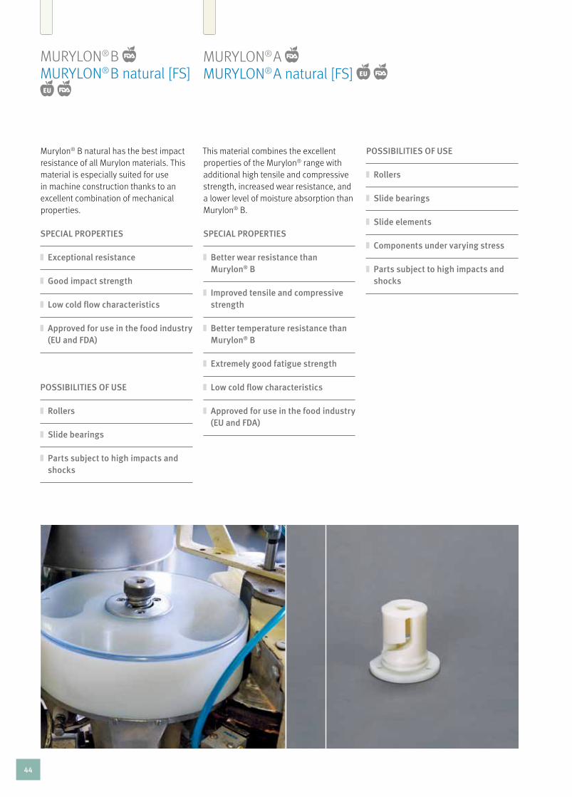
MuryLOn® B MuryLOn® B natural [FS] EU
Murylon® B natural has the best impact resistance of all Murylon materials. This material is especially suited for use in machine construction thanks to an excellent combination of mechanical properties.
SPECIAl PROPERTIES
Exceptional resistance
Good impact strength
low cold flow characteristics
Approved for use in the food industry (EU and FDA)
POSSIBIlITIES OF USE
Rollers
Slide bearings
Parts subject to high impacts and shocks
MuryLOn® A MuryLOn® A natural [FS] EU
This material combines the excellent properties of the Murylon® range with additional high tensile and compressive strength, increased wear resistance, and a lower level of moisture absorption than Murylon® B.
SPECIAl PROPERTIES
Better wear resistance than Murylon® B
Improved tensile and compressive strength
Better temperature resistance than Murylon® B
Extremely good fatigue strength
low cold flow characteristics
Approved for use in the food industry (EU and FDA)
POSSIBIlITIES OF USE
Rollers
Slide bearings
Slide elements
Components under varying stress
Parts subject to high impacts and shocks
44
Pl
AS
TIC
ST
EC
HN
ICA
l M
AT
ER
IAlS
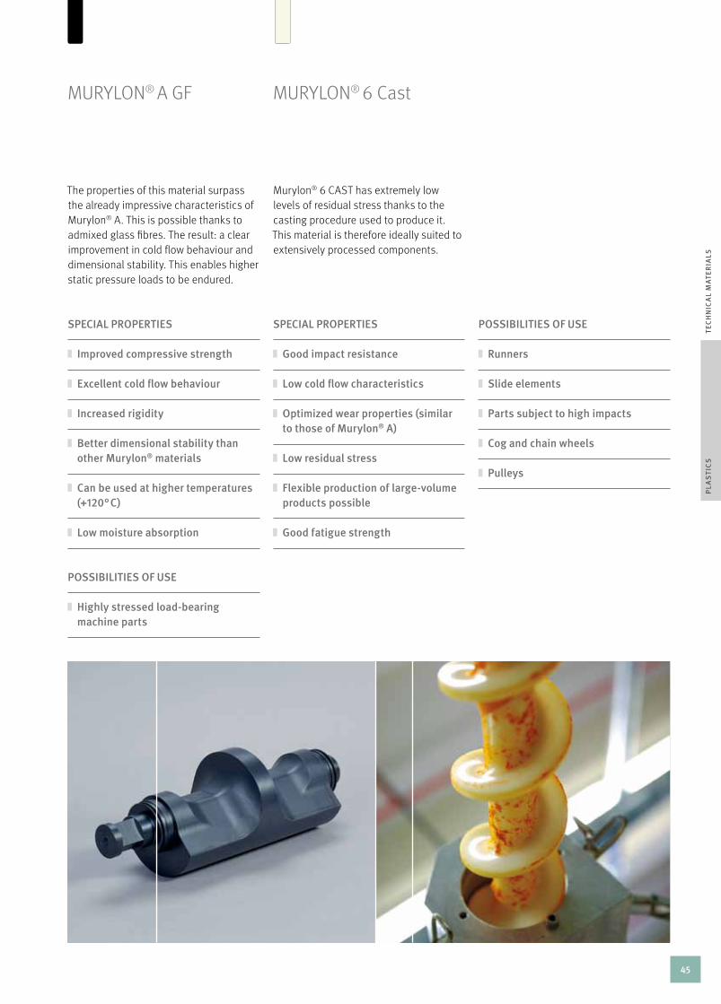
MuryLOn® A GF
The properties of this material surpass the already impressive characteristics of Murylon® A. This is possible thanks to admixed glass fibres. The result: a clear improvement in cold flow behaviour and dimensional stability. This enables higher static pressure loads to be endured.
SPECIAl PROPERTIES
Improved compressive strength
Excellent cold flow behaviour
Increased rigidity
Better dimensional stability than other Murylon® materials
Can be used at higher temperatures (+120° C)
low moisture absorption
POSSIBIlITIES OF USE
Runners
Slide elements
Parts subject to high impacts
Cog and chain wheels
Pulleys
POSSIBIlITIES OF USE
Highly stressed load-bearing machine parts
MuryLOn® 6 cast
Murylon® 6 cAST has extremely low levels of residual stress thanks to the casting procedure used to produce it. This material is therefore ideally suited to extensively processed components.
SPECIAl PROPERTIES
Good impact resistance
low cold flow characteristics
Optimized wear properties (similar to those of Murylon® A)
low residual stress
Flexible production of large-volume products possible
Good fatigue strength
45

MurDOPOL®
The main advantage of this material is its fantastic ability to create firm plastic/metal connections. This is made possible by the casting procedure used in its production, which involves casting around a steel core. The plastic and metal cutting deformation provides an absolutely accurate rotation for cog wheels and rollers. Murdopol® has extremely high shock and impact resistance characteristics and good emergency running characteristics thanks to its high wear resistance.
SPECIAl PROPERTIES
Good shock and impact resistance
low residual stress
Metal core surrounded by cast plastic available
Good damping and vibration behaviour
lowest moisture absorption of all polyamides
Good resistance to chemicals
Dimensionally stable
POSSIBIlITIES OF USE
Cog wheels with steel core
Pulleys
Humid usage sites
Parts subject to high impacts
Cam disks and sprockets
46

Pl
AS
TIC
ST
EC
HN
ICA
l M
AT
ER
IAlS
MuryTAL® c MuryTAL® c natural [FS] EU
Thanks to their extremely low absorption of moisture, Murytal® materials are ideally suited for use as electronic isolation components. A fine crystalline structure and high yield strength mean that Murytal® c has a high ability to regain its original form.
SPECIAl PROPERTIES
High rigidity
Excellent ability to regain its form
Extremely good electric isolation properties
Practically no moisture absorption
Good resistance to chemicals (pH 4 – 13)
Approved for use in the food industry (EU and FDA) (Natural)
Extremely good machinability
Hydrolysis resistant to 80° C
POSSIBIlITIES OF USE FOR All MURyTAl® MATERIAlS
Slide elements
Cog wheels
Cams
Snap-on connections
MuryTAL® c blue [FS] EU
Provided with the same properties as Murytal® c natural, the blue plastic is ideal for use in the food sector thanks to its colour.
SPECIAl PROPERTIES
High rigidity
Excellent ability to regain its form
Extremely good electric isolation properties
Practically no moisture absorption
Good resistance to chemicals (pH 4 – 13)
Approved for use in the food industry (EU and FDA)
Extremely good machinability
Hydrolysis resistant to 80° C
· The
Fo
od
Sa
Fe [FS] producT wo
rld
·
of mu rtfeldt
47

POSSIBIlITIES OF USE FOR All MURyTAl® MATERIAlS
Slide elements
Cog wheels
Cams
Snap-on connections
MuryTAL® h
In addition to the excellent properties of Murytal® c, Murytal® h is stronger and more rigid with a lower expansion coefficient.
SPECIAl PROPERTIES
Higher rigidity than Murytal® C
Excellent ability to regain its form
Extremely good electric isolation properties
Practically no moisture absorption
Good resistance to chemicals (pH 4 – 9)
Approved for use in the food industry (EU and FDA)
Extremely good machinability
MuryTAL® ESD
Additives make this material conductive. The mechanical properties of the material are retained almost in their entirety.
SPECIAl PROPERTIES
Suitable for devices and machines subject to Directive 94/9/EC (ATEX 95)
48

MuryLAT® MuryLAT® [FS] EU
Thanks to its extremely low absorption of moisture and low expansion coefficient, Murylat® is ideally suited for the processing of precision parts. Murylat® has an extremely high hardness grade and can withstand extreme static stresses exceptionally well.
SPECIAl PROPERTIES
High creep strength – even at high temperatures
Very good dimensional stability
low moisture absorption
Approved for use in the food industry (EU and FDA) (Natural)
Extremely good electric isolation properties
POSSIBIlITIES OF USE FOR MURylAT®
Machine parts with narrow tolerances
Bearing and transmission elements
Highly stressed chain guide rails
Chain wheelsSPECIAl PROPERTIES
Increased wear resistance
Better slide properties
High creep strength – even at high temperatures
Very good dimensional stability
High dynamic load-bearing capacity
low moisture absorption
Approved for use in the food industry (EU and FDA)
MuryLAT® SP MuryLAT® SP [FS] EU
Murylat® SP combines the properties of Murylat® with improved wear and friction characteristics. It also has increased dynamic resilience which, for example, significantly reduces the required drive power for your plants. This is made possible by the homogeneous distribution of solid lubricant.
POSSIBIlITIES OF USE FOR MURylAT® SP
Wear-resistant, highly stressed slide elements with narrow tolerances
Bushes/sliding bearings
Guides
Pl
AS
TIC
ST
EC
HN
ICA
l M
AT
ER
IAlS
· The
Fo
od
Sa
Fe [FS] producT wo
rld
·
of mu rtfeldt
49

The use of this highly temperature- resistant polyamide enables reliable operation up to a constant service temperature of +155° c. The material retains its rigidity and creep strength over the entire temperature range far better than other Murylon® types. Thanks to its increased resistance against oxidative degradation, it is usually used in applications at above +80° c.
MuryLOn® hT
SPECIAl PROPERTIES
Highly wear-resistant and good slide properties, especially at high tempe- ratures
Good resistance to thermal aging
High creep resistance
POSSIBIlITIES OF USE
Sliding bearings
Chain guide rails and guides for use at high temperatures
high-performance materials
50

MurInyL®
This material is ideally suited for use in the food sector and medical industry. As a fluorinated plastic, Murinyl® is exceptionally resistant to chemicals, hydrolysis, and sterilization. Moreover, the properties of the material change very little even at high service temperatures and after long-term exposure to uV radiation, meaning that Murinyl® is ideally suited for a wealth of applications both inside and outside.
SPECIAl PROPERTIES
Good wear resistance
Good rigidity
Higher compressive strength than Murflor®
High constant service temperature
Good resistance to chemicals
Resistant to sterilization
No stress corrosion possible
Very good resistance to UV rays and adverse weather conditions
No moisture absorption
Approved for use in the food industry (EU and FDA)
POSSIBIlITIES OF USE
Construction of chemical apparatus
Valve and pump parts
Pharmaceutical and food sectors
Pl
AS
TIC
SH
IGH
-PE
RFO
RM
AN
CE
MA
TE
RIA
lS
51

MurFLOr®
Murflor® materials are ideally suited to use in applications that require an excellent resistance to chemicals and heating steam. Murflor®’s working range starts at -200° c and can extend to +260° c with no mechanical load. Murflor® also has the lowest dynamic friction coefficient of all thermoplastics.
SPECIAl PROPERTIES
Best dynamic friction properties of all thermoplastics
No stick/slip effect
Very good anti-adhesion properties
Electrically isolating
Very high resistance to chemicals
Very high resistance to hydrolysis
Very tough, even at low temperatures
Approved for use in the food industry (FDA)
POSSIBIlITIES OF USE
Construction of chemical apparatus
Sliding guides and seals for use at high temperatures
Slide bearings
52

SPECIAl PROPERTIES
lower sliding wear than Murflor®
Good slide properties
low stick/slip effect
Higher compressive strength than Murflor® POSSIBIlITIES OF USE
Sliding guides and slide bearings
MurFLOr® + carbon
The integration of 25 % carbon increases the wear resistance, hardness, and creep strength of this material. Murflor® + carbon is used, for example, when electrical conductivity is required and Material ”S”® Black Antistatic cannot be used because the ambient temperature is too high.
MurFLOr® + Bronze
The addition of 60 % bronze to the base material reduces the expansion coefficient and gives lower sliding wear.
SPECIAl PROPERTIES
Higher wear resistance than Murflor®
Very good slide properties
low stick/slip effect
Electrically conductive
Suitable for devices and machines subject to Directive 94/9/EC (ATEX 95) POSSIBIlITIES OF USE
Sliding guides and slide bearings
Pl
AS
TIC
SH
IGH
-PE
RFO
RM
AN
CE
MA
TE
RIA
lS
53

MurInIT® SP MurInIT® SP [FS] EU
Thanks to the low fibre content and integrated solid lubricant, this high-performance material offers an excellent combination of good slide and wear behaviour, high strength, and dimensional stability – even at high temperatures. Murinit® SP also has a good resistance to chemicals and hydrolysis.
SPECIAl PROPERTIES
High wear resistance
Good slide properties
Good resistance to chemicals and hydrolysis
Excellent creep and compressive strength
Good electrical isolation properties
low thermal expansion coefficient
Approved for use in the food industry (EU and/or FDA)
POSSIBIlITIES OF USE
Wear parts subject to temperature stress
Slide elements
· The
Fo
od
Sa
Fe [FS] producT wo
rld
·of mu rtfeldt
54

Pl
AS
TIC
SH
IGH
-PE
RFO
RM
AN
CE
MA
TE
RIA
lS
MurPEc® MurPEc® [FS] EU
In comparison with other thermoplastics, Murpec® has an exceptionally low thermal expansion coefficient. This property provides optimum dimensional stability and means that dimensions do not change even if used in wet environments. Because of the high glass transition temperature, the material’s rigidity and strength are retained almost in their entirety even at high temperatures. Murpec® materials are extremely resistant to deformation and exceptionally abrasion-proof.
SPECIAl PROPERTIES
High wear resistance
low expansion coefficient
Electrically isolating
High temperature resistance
Flame-resistant
High compressive strength
High resistance to energy radiation
Excellent resistance to chemicals and heating steam
Approved for use in the food industry (EU and/or FDA)
POSSIBIlITIES OF USE
Sliding guides
Cog wheels
Parts subject to temperature stress
· The
Fo
od
Sa
Fe [FS] producT wo
rld
·
of mu rtfeldt
55
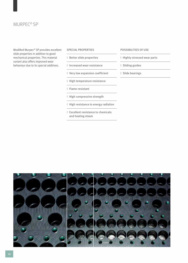
MurPEc® SP
Modified Murpec® SP provides excellent slide properties in addition to good mechanical properties. This material variant also offers improved wear behaviour due to its special additives.
SPECIAl PROPERTIES
Better slide properties
Increased wear resistance
Very low expansion coefficient
High temperature resistance
Flame-resistant
High compressive strength
High resistance to energy radiation
Excellent resistance to chemicals and heating steam
POSSIBIlITIES OF USE
Highly-stressed wear parts
Sliding guides
Slide bearings
56
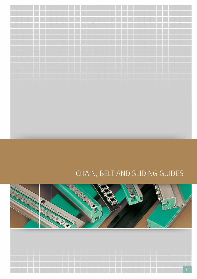
chaIn, belt and slIdIng guIdes
57

chAIn, BELT, AnD SLIDInG GuIDES – TABLE OF cOnTEnTS
Introduction 58
Overview of chain Guides 59
Special Profiles 60 – 61
chain, Belt, and Sliding Guides 62
construction with Plastic Guides 63
Steel c Profiles 64
Selection Table for Steel c Profiles 65
Fastening of Steel c Profiles 66
T-head Bolts 67
Fixing the Steel c-Profile with threaded bolt welding technology 68
chain Guides for roller chains as per DIn 8187 69 – 85
Types: T, cT, T-Duplex, cT-duplex, T-Triplex, cT-Triplex, Tu, cTu, TS, cTS, u, cu, K, cK, cKg, cKg 14H, cKg 15v, eTa
chain Guides for round Link chains as per DIn 766/764 86 – 87
Types: r, cru, crG, crO
Overview of Belt Guides/Belt Guides 88 – 93
Types: rr, rrc, kr, krc, Fr, Frc, Fk, Fkc
chain racks 94
Profiles for conveying and Transportation 95 – 103
Sliding Guides, Type cF, rail guides as insertion and clip Profiles, Bands, Slip-On Profiles, Profiles for Slat Band chains, curve Guides for Slat Band chains
Guides for modular belts 104 – 105
58

OVErVIEW OF chAIn GuIDES
Murtfeldt offers an extensive standard range of guides for roller chains. We have a total of 20 different types of guide for roller chains and four for round link chains. you can also choose
between our high-quality Original Material ”S”® Green and our more economical Material ”S”® 1000 Green.
for roller chains (dIn 8187) and round link chains (dIn 766/764)
Type T – page 69 Type cT – page 70 Type T-Duplex – page 71 Type cT-Duplex – page 72
Type k – page 80Type u – page 78 Type cu – page 79Type TS – page 76 Type cTS – page 77
Type Tu – page 75 Type cTu – page 75Type T-Triplex – page 73 Type cT-Triplex – page 74
chain guides for round link chains as per dIn 766/764
Type r – page 86 Type cru – page 86 Type crG – page 87 Type crO – page 87
Type ck – page 81 Type ETA – page 85Type ckG – page 82 Type ckG 15V – page 84Type ckG 14h – page 83
chain guides for roller chains as per dIn 8187 (dIn 8188 catalogue on request)
CH
AIN
, B
ElT
, A
ND
SlI
DIN
G G
UID
ES
TAB
lE O
F C
ON
TE
NTS
/ O
VE
RV
IEW
OF
CH
AIN
GU
IDE
S
59

SPEcIAL PrOFILES
Our standard range of profiles offers many solutions for equipping your machines. Should we not have the design you require in our range, we would be happy to manufacture it to your individual specification. Get in touch with our application engineers or our Field Sales team.
We can also offer you the option of processing documents and drawings online and in real time together with our staff.
When the standard designs are not enough
60

CH
AIN
, B
ElT
, A
ND
SlI
DIN
G G
UID
ES
SP
EC
IAl
PR
OFI
lES
61

chain guides
Where there is friction, there is wear. This is especially the case for applications where metallic materials are used. For example, for chains that run on metal guides, regular lubrication is absolutely vital. The aim is to achieve quiet, smooth running and long-term functional reliability.
Murtfeldt chain guides protect your chains. They guarantee optimum running properties at the same time as extremely high wear resistance. The tried-and-tested Material ”S”® and the economical alternative ”S”® 1000 have ideal material properties that make them well-suited for use as guides for roller and round link chains.
stock and individual production
Our warehouse stocks an extensive range of guides for roller chains that comply with DIn 8187 and round link chains that comply with dIn 766 and dIn 764.
In addition, we can manufacture economical and reliable special guides in accordance with your specifications – even in small lot sizes.
chAIn, BELT, AnD SLIDInG GuIDES
Advantages of Murtfeldt chain guides
High wear resistance
Very good slide properties
Self-lubricating (no need for any oil
lubrication at all) Extremely impact and break resistant,
even at very low temperatures (up to -250° C)
High chemical resistance
Vibration-reducing properties
No moisture absorption
No corrosion
Approved for use in the food industry –
EU and FDA (Original Material ”S”® [FS])
62

CH
AIN
, B
ElT
, A
ND
SlI
DIN
G G
UID
ES
INT
RO
DU
CT
ION
/ C
ON
STR
UC
TIO
N W
ITH
PlA
STI
C G
UID
ES
construction using thermoplastics requires careful consideration beforehand. The conditions of use have a direct influence on the material selection and design of the plastic guides. you should answer the following questions in advance:
To what static and dynamic loads will the guide
be exposed? To what environmental factors, such as chemicals, hot
or cold water, steam, or contaminants will the material be exposed? Will there be direct contact with foods?
How high is the working temperature?
How is the guide to be attached to a C profile
(screwed on or inserted)?
cOnSTrucTIOn WITh PLASTIc GuIDES
In comparison with metallic materials, thermoplastics have a higher coefficient of linear thermal expansion.
calculation
When calculating the expansion, the anticipated difference between the assembly and minimum and maximum working temperatures is to be taken into account. The coefficient of linear thermal expansion of the material is used to precisely calculate the maximum elongation when the temperature rises and the reduction when the temperature drops (see formula below). The required movement space for the material can thus be taken into account before installation takes place. There are different fastening options depending on the application (see page 64 – 68).
formula for calculating elongation
ΔL = L x α x ΔT
ΔL = ElongationL = Initial lengthα = coefficient of linear thermal expansionΔT = Temperature difference in ° c
63

regardless of the fastening method chosen, you should design your plant so that the material can expand. The easiest and most efficient fastening method is to fasten the guide using our steel c profiles. unlike metals, thermoplastics are particularly predisposed to an increase/reduction in length when temperature variations occur. Mounting a guide in a steel c profile makes sense because of the freedom of movement afforded to the slide bar. This method also makes it easy to replace plastic guides. Steel c profiles also act as stable fasteners and can be welded or screwed on as required. We recommend the use of DIn screws or special assembly using T-head bolts (see page 66). We also offer fixing of steel c profiles with threaded bolt welding technology.
AVAIlABlE VARIANTS Galvanized (Stocked)
Stainless steel (Stocked)
Untreated (upon request)
STEEL c PrOFILES
The advantages of Murtfeldt steel C profiles
Simple assembly/disassembly of
the guide system Quick replacement procedure if wear
occurs Plastic profiles only need to be secured
against being pushed out once Simple alignment of the guide system
No distortion occurs when mounting
the steel C profile if screws are used Guide can increase/decrease in length if
temperature variations occur
single or varying chain/belt/cargo direction
When expansion takes place, the plastic guide moves up in the opposite direction to the running/conveying direction. you should therefore make sure that sufficient space for the anticipated expansion is provided at the start of the plastic guide.
64

CH
AIN
, B
ElT
, A
ND
SlI
DIN
G G
UID
ES
ST
EE
l C
PR
OFI
lES
/ S
ElE
CT
ION
TA
BlE
CH
AIN
, B
ElT
, A
ND
SlI
DIN
G G
UID
ES
profile no. B h b s l length article no.galvanized
article no. v2a
article no. nongalvanized
C1 24 5.2 17.5 1 - 2000 351 020 001 351 020 101
3000 351 030 001 351 030 101
6000 351 060 001 351 060 101
C3 20 10 10 1.5 - 2000 351 020 003 351 020 103
3000 351 030 003 351 030 103
6000 351 060 003 351 060 103 351 060 203
C4 50 10 35 2 - 2000 351 020 004 351 020 104
6000 351 060 004 351 060 104
C5 28 12 14 2 - 2000 351 020 005 351 020 105
3000 351 030 005 351 030 105
6000 351 060 005 351 060 105 351 060 205
C6 80 10 65 2 - 2000 351 020 006 351 020 106
6000 351 060 006 351 060 106
C7 28 16 14 2.5 - 2000 351 020 007 351 020 107
6000 351 060 007 351 060 107 351 060 207
C9 38 18 22 2.5 - 2000 351 020 009 351 020 109
3000 351 030 009 351 030 109
6000 351 060 009 351 060 109 351 060 209
C10 30 24 20 1.5 - 2000 351 020 010 351 020 110
6000 351 060 010 351 060 110 351 060 210
C11 45 40 31 2 - 2000 351 020 011 351 020 111
6000 351 060 011 351 060 111 351 060 211
C12 60 20 36 2.5 - 2000 351 020 012 351 020 112
6000 351 060 012 351 060 112
C13 65 55 40 3 - 2000 351 020 013 351 020 113
6000 351 060 013 351 060 113
C14 H 31 25 20 2 47 2000 351 020 014 351 020 114
3000 351 030 014 351 030 114
6000 351 060 014 351 060 114
C15 V 31 25 20 2 53 2000 351 020 015 351 020 115
3000 351 030 015 351 030 115
6000 351 060 015 351 060 115
SELEcTIOn TABLEGalvanized, nongalvanized or stainless steel c profiles
Dimensions in mm c 14h and c 15v steel profiles with punch hole in mounting rail
hole spacing aggregate tolerance: Max. 0.75mm/m
0.3
0.3
0.3
0.3
0.3
0.15
12.5
8.9
65

one-track fastening (standard) two-track fastening (optional for wide c6 and c12 profiles)
With t-head bolts
FASTEnInG OF STEEL c PrOFILES
We can bore or punch individual hole patterns if you provide us with an appropriate drawing. For T-head bolt dimensions, see the following page.
T-head bolts provide a secure connection between your machine element and our c profiles. As a rule, a simplex connection is used. Duplex connections are available if desired. Our application technology department will be glad to advise you to ensure that you obtain the best implementation for your requirements.
Milled groove for bolt head prevents simultaneous
turning of T-head bolt Fastening of screw nuts from below (with T-head bolts)
Punching and boring of required hole pattern in
accordance with individual drawings
66

PR
OFI
lEFA
ST
EN
ING
OF
ST
EE
l C
PR
OFI
lES
/ T
-HE
AD
BO
lTS
CH
AIN
, B
ElT
, A
ND
SlI
DIN
G G
UID
ES
thread (M x l) suitable for these steel c profiles a in mm B in mm h in mm Material article no. type
M6x20 C1, C3, C4, C5, C6, C7, C9, C10, C11, C12, C13 18.0 9.5 4 galvanised 352010001 -
M6x20 C1, C4, C5, C6, C7, C9, C12 15.5 9.0 6 galvanised 352010005 20/12
M6x30 C1, C4, C5, C6, C7, C9, C12 15.5 9.0 6 galvanised 352010003 20/12
M6x40 C1, C4, C5, C6, C7, C9, C12 15.5 9.0 6 galvanised 352010004 20/12
M8x20 C4, C6, C7, C9, C12 15.5 9.0 6 galvanised 352010008 20/12
M8x30 C4, C6, C7, C9, C12 15.5 9.0 6 galvanised 352010006 20/12
M8x40 C4, C6, C7, C9, C12 15.5 9.0 6 galvanised 352010007 20/12
M8x20 C4, C6, C7, C9, C12 23.0 11.0 6 galvanised 352010011 28/15
M8x30 C4, C6, C7, C9, C12 23.0 11.0 6 galvanised 352010019 28/15
M8x40 C4, C6, C7, C9, C12 23.0 11.0 6 galvanised 352010014 28/15
M10x20 C4, C6, C7, C9, C11, C12, C13 23.0 11.0 7 galvanised 352010020 28/15
M10x30 C4, C6, C7, C9, C11, C12, C13 23.0 11.0 7 galvanised 352010012 28/15
M10x40 C4, C6, C7, C9, C11, C12, C13 23.0 11.0 7 galvanised 352010013 28/15
M10x20 C6, C9, C12 31.0 13.5 9 galvanised 352010015 38/17
M10x30 C6, C9, C12 31.0 13.5 9 galvanised 352010016 38/17
M12x40 C6, C11, C12, C13 31.0 13.5 9 galvanised 352010017 38/17
M6x20 C1, C3, C4, C5, C6, C7, C9, C10, C11, C12, C13 18.0 9.5 4 V2A 352010002 -
M8x20 C4, C6, C7, C9, C12 15.5 9.0 6 V2A 352010025 20/12
M8x30 C4, C6, C7, C9, C12 15.5 9.0 6 V2A 352010026 20/12
T-hEAD BOLTSGalvanized/stainless steel
Please speak with our application technology department to determine the best T-head screw for your needs. We can provide the appropriate models including nuts for one-track and two-track connections.
67

FIXInG ThE STEEL c-PrOFILE WITh ThrEADED BOLT WELDInG TEchnOLOGy
The tip of the bolt contacts the workpiece. The arc is initiated.
The arc produces a fine melting zone on the bolt and the workpiece.
The bolt is plunged into the weld pool, the material solidifies and is welded to the bolt.
Individual fixing of the welded bolt to your specification
at any position on the steel-C-profile Cost-effective process as no need for complex
preparatory work Available for galvanised and stainless steel profiles
Threaded bolts up to M8
Max. bolt length 40 mm
thread size length Material
M4 12 V2A
M5 8 V2A
M5 20 V2A
M5 20 steel
M6 25 V2A
M6 25 steel
M8 15 V2A
M8 15 steel
M8 20 V2A
M8 20 steel
M8 30 V2A
M8 30 steel
Other dimensions on request.
68

Other dimensions on request.
dIn 8187 chain no. chain dimensions in inches B h b h article no.
06B-1 3/8‘‘ x 7/32‘‘ 15 10 5,4 1,5 221 010 002
083-1 1/2‘‘ x 3/16‘‘ 15 10 4,5 1,5 221 010 003
085-1 1/2‘‘ x 1/4‘‘ 20 10 6,2 2,2 221 010 004
08B-1 1/2‘‘ x 5/16‘‘ 20 10 7,4 2,2 221 010 005
08B-1 1/2‘‘ x 5/16‘‘ 20 15 7,4 2,2 221 010 006
08B-1 1/2‘‘ x 5/16‘‘ 20 20 7,4 2,2 221 010 007
08B-1 1/2‘‘ x 5/16‘‘ 20 30 7,4 2,2 221 010 008
- 5/8‘‘ x 1/4‘‘ 20 10 6,2 2,6 221 010 009
10B-1 5/8‘‘ x 3/8‘‘ 20 10 9,3 2,6 221 010 010
10B-1 5/8‘‘ x 3/8‘‘ 20 15 9,3 2,6 221 010 011
10B-1 5/8‘‘ x 3/8‘‘ 20 20 9,3 2,6 221 010 012
10B-1 5/8‘‘ x 3/8‘‘ 20 30 9,3 2,6 221 010 013
12B-1 3/4‘‘ x 7/16‘‘ 25 10 11,3 2,4 221 010 014
12B-1 3/4‘‘ x 7/16‘‘ 25 15 11,3 2,4 221 010 015
12B-1 3/4‘‘ x 7/16‘‘ 25 20 11,3 2,4 221 010 016
12B-1 3/4‘‘ x 7/16‘‘ 25 30 11,3 2,4 221 010 017
16B-1 1‘‘ x 17 mm 40 15 16,0 3,5 221 010 018
16B-1 1‘‘ x 17 mm 40 20 16,0 3,5 221 010 019
16B-1 1‘‘ x 17 mm 40 30 16,0 3,5 221 010 020
20B-1 1 1/4‘‘ x 3/4‘‘ 45 15 18,0 4,2 221 010 021
24B-1 1 1/2‘‘ x 1‘‘ 60 15 24,0 5,5 221 010 022
28B-1 1 3/4‘‘ x 31 mm 75 20 30,0 6,8 221 010 023
32B-1 2‘‘ x 31 mm 80 20 30,0 7,7 221 010 024
TyPE T
chain Guides for roller chains as per dIn 8187
Dimensions in mm · Separate ASA/JIS product catalogue available.
CH
AIN
, B
ElT
, A
ND
SlI
DIN
G G
UID
ES
AT
TAC
HM
EN
T D
ES
STA
Hl-
C-P
RO
FIlS
MIT
GE
WIN
DE
BO
lz
EN
-SC
HW
EIS
ST
EC
HN
IK /
CH
AIN
GU
IDE
S F
OR
RO
llE
R C
HA
INS
69

TyPE cT
dIn 8187 chain no. chain dimensions in inches
c profile type B1 B2 h hc b h article no.
06B-1 3/8‘‘ x 7/32‘‘ 17 14 17 5.4 1.5 221 210 015
C3 20 351 020 003
083-1 1/2‘‘ x 3/16‘‘ 17 14 17 4.5 1.5 221 210 002
C3 20 351 020 003
085-1 1/2‘‘ x 1/4‘‘ 17 14 17 6.2 2.2 221 210 003
C3 20 351 020 003
08B-1 1/2‘‘ x 5/16‘‘ 20 10 11 7.4 2.2 221 210 001
C1 24 351 020 001
08B-1 1/2‘‘ x 5/16‘‘ 17 14 17 7.4 2.2 221 210 004
C3 20 351 020 003
- 5/8‘‘ x 1/4‘‘ 17 14 17 6.2 2.6 221 210 005
C3 20 351 020 003
10B-1 5/8‘‘ x 3/8‘‘ 17 14 17 9.3 2.6 221 210 006
C3 20 351 020 003
12B-1 3/4‘‘ x 7/16‘‘ 20 14 17 11.3 2.4 221 210 007
C3 20 351 020 003
12B-1 3/4‘‘ x 7/16‘‘ 24 14 18 11.3 2.4 221 210 008
C5 28 351 020 005
16B-1 1‘‘ x 17 mm 24 14 18 16 3.5 221 210 009
C5 28 351 020 005
20B-1 1 1/4‘‘ x 3/4‘‘ 28 14 18 18 4.2 221 210 010
C5 28 351 020 005
24B-1 1 1/2‘‘ x 1‘‘ 33 23 30 24 5.5 221 210 011
C9 38 351 020 009
28B-1 1 3/4‘‘ x 31 mm 38 23 30 30 6.8 221 210 012
C9 38 351 020 009
32B-1 2‘‘ x 31 mm 38 23 30 30 7.7 221 210 013
C9 38 351 020 009
32B-1 2‘‘ x 31 mm 60 25 35 30 7.7 221 210 014
C12 60 351 020 012
Dimensions in mm · Separate ASA/JIS product catalogue available.
70

CH
AIN
, B
ElT
, A
ND
SlI
DIN
G G
UID
ES
CH
AIN
GU
IDE
S F
OR
RO
llE
R C
HA
INS
TyPE T-DuPLEX
dIn 8187 chain no.
chain dimensions in inches
B h b h e+b article no.
06B-2 3/8‘‘ x 7/32‘‘ 25.0 10 5.3 1.5 15.6 221 010 025
08B-2 1/2‘‘ x 5/16‘‘ 35.0 10 7.2 2.2 21.2 221 010 026
08B-2 1/2‘‘ x 5/16‘‘ 35.0 15 7.2 2.2 21.2 221 010 027
08B-2 1/2‘‘ x 5/16‘‘ 35.0 20 7.2 2.2 21.2 221 010 028
08B-2 1/2‘‘ x 5/16‘‘ 35.0 30 7.2 2.2 21.2 221 010 029
10B-2 5/8‘‘ x 3/8‘‘ 40.0 10 9.0 2.6 25.6 221 010 030
12B-2 3/4‘‘ x 7/16‘‘ 45.0 15 10.9 2.4 30.4 221 010 031
12B-2 3/4‘‘ x 7/16‘‘ 45.0 10 10.9 2.4 30.4 221 010 032
16B-2 1‘‘ x 17 mm 47.8 15 15.8 3.5 47.8 221 010 033
20B-2 1 1/4‘‘ x 3/4‘‘ 54.7 15 18.2 4.2 54.7 221 010 034
24B-2 1 1/2‘‘ x 1‘‘ 72.0 20 23.6 5.5 72.0 221 010 035
28B-2 1 3/4‘‘ x 31 mm 88.4 25 28.8 6.8 88.4 221 010 036
32B-2 2‘‘ x 31 mm 87.4 30 28.8 7.7 87.4 221 010 037
Dimensions in mm · Separate ASA/JIS product catalogue available.
b b
e+b
B
B (e+b)
b
h
H
h
H
b
2e+b
h
H
B
b
B (2e+b)
h
H
b
2e+b
B1
B2
H
Hc
b
B1 (2e+b)
H
Hc
h
h
B2
b b
e+b
B
B (e+b)
b
h
H
h
H
b
2e+b
h
H
B
b
B (2e+b)
h
H
b
2e+b
B1
B2
H
Hc
b
B1 (2e+b)
H
Hc
h
h
B2
71

TyPE cT-DuPLEX
dIn 8187 chain no.
chain dimensions in inches
c profile type
B1 B2 h hc b h article no.
06B-2 3/8‘‘ x 7/32‘‘ 15.6 14 17 5.3 1.5 221 210 022
C3 20 351 020 003
08B-2 1/2‘‘ x 5/16‘‘ 21.2 14 17 7.2 2.2 221 210 016
C3 20 351 020 003
10B-2 5/8‘‘ x 3/8‘‘ 25.6 14 17 9.0 2.6 221 210 017
C3 20 351 020 003
12B-2 3/4‘‘ x 7/16‘‘ 30.4 15 20 10.9 2.4 221 210 018
C5 28 351 020 005
16B-2 1‘‘ x 17 mm 47.8 20 27 15.8 3.5 221 210 019
C9 38 351 020 009
20B-2 1 1/4‘‘ x 3/4‘‘ 54.7 22 30 18.2 4.2 221 210 020
C12 60 351 020 012
24B-2 1 1/2‘‘ x 1‘‘ 72.0 25 35 23.6 5.5 221 210 021
C12 60 351 020 012
Dimensions in mm · Separate ASA/JIS product catalogue available.
72

CH
AIN
GU
IDE
S F
OR
RO
llE
R C
HA
INS
CH
AIN
, B
ElT
, A
ND
SlI
DIN
G G
UID
ES
TyPE T-TrIPLEX
dIn 8187 chain no. chain dimensions in inches B h b h 2e+b article no.
06B-3 3/8‘‘ x 7/32‘‘ 35.0 10 5.3 1.5 25.9 221 010 038
08B-3 1/2‘‘ x 5/16‘‘ 45.0 10 7.1 2.2 34.9 221 010 039
10B-3 5/8‘‘ x 3/8‘‘ 55.0 10 8.9 2.6 42.1 221 010 040
12B-3 3/4‘‘ x 7/16‘‘ 60.0 15 10.7 2.4 49.7 221 010 041
16B-3 1‘‘ x 17 mm 79.5 20 15.7 3.5 79.5 221 010 042
20B-3 1 1/4‘‘ x 3/4‘‘ 91.0 20 18.0 4.2 91.0 221 010 043
24B-3 1 1/2‘‘ x 1‘‘ 120.0 25 23.4 5.5 120.0 221 010 044
Dimensions in mm · Separate ASA/JIS product catalogue available.
b b
e+b
B
B (e+b)
b
h
H
h
H
b
2e+b
h
H
B
b
B (2e+b)
h
H
b
2e+b
B1
B2
H
Hc
b
B1 (2e+b)
H
Hc
h
h
B2
b b
e+b
B
B (e+b)
b
h
H
h
H
b
2e+b h
H
B
b
B (2e+b)
h
H
b
2e+b
B1
B2 H
Hc
b
B1 (2e+b)
H
Hc
h
h
B2
From 06B-3 to 12B-3 From 16B-3 to 24B-3
73

TyPE cT-TrIPLEX
dIn 8187 chain no.
chain dimensions in inches
c profile type
B1 B2 h hc b h 2e + b article no.
06B-3 3/8‘‘ x 7/32‘‘ 30.0 15 20 5.3 1.5 25.9 221 210 023
C5 28 351 020 005
08B-3 1/2‘‘ x 5/16‘‘ 34.9 15 20 7.1 2.2 34.9 221 210 024
C5 28 351 020 005
10B-3 5/8‘‘ x 3/8‘‘ 50.0 15 17 8.9 2.6 42.1 221 210 025
C4 50 351 020 004
12B-3 3/4‘‘ x 7/16‘‘ 49.7 18 20 10.7 2.4 49.7 221 210 026
C4 50 351 020 004
16B-3 1‘‘ x 17 mm 79.5 20 22 15.7 3.5 79.5 221 210 027
C6 80 351 020 006
20B-3 1 1/4‘‘ x 3/4‘‘ 91.0 20 22 18.0 4.2 91.0 221 210 028
C6 80 351 020 006
Dimensions in mm · Separate ASA/JIS product catalogue available.
b b
e+b
B
B (e+b)
b
h
H
h
H
b
2e+b
h
H
B
b
B (2e+b)
h
H
b
2e+b
B1
B2
H
Hc
b
B1 (2e+b)
H
Hc
h
h
B2
b b
e+b
B
B (e+b)
b
h
H
h
H
b
2e+b
h
H
B
b
B (2e+b)
h
H
b
2e+b
B1
B2
H
Hc
b
B1 (2e+b)
H
Hc
h
h
B2
From 06B-3 to 10B-3 From 12B-3 to 20B-3
74

CH
AIN
, B
ElT
, A
ND
SlI
DIN
G G
UID
ES
CH
AIN
GU
IDE
S F
OR
RO
llE
R C
HA
INS
TyPE Tu
TyPE cTu
dIn 8187 chain no. chain dimensions in inches B h b h article no.
- 3/8‘‘ x 5/32‘‘ 15 10 12 2.2 221 110 010
083-1 1/2‘‘ x 3/16‘‘ 15 10 12 2.2 221 110 011
dIn 8187 chain no.
chain dimensions in inches
c profile type B1 B2 h hc b h article no.
- 3/8‘‘ x 5/32‘‘ 17 14 17 12 2.2 221 310 010
C3 20 351 020 003
083-1 1/2‘‘ x 3/16‘‘ 17 14 17 12 2.2 221 310 010
C3 20 351 020 003
Dimensions in mm · Separate ASA/JIS product catalogue available.
Dimensions in mm · Separate ASA/JIS product catalogue available.
75

TyPE TS
dIn 8187 chain no.
chain dimensions in inches
B h b1 b2 h1 h2 article no.
06B-1 3/8‘‘ x 7/32‘‘ 20 10 3.8 13.0 1.5 1.1 221 110 001
083-1 1/2‘‘ x 3/16‘‘ 20 10 3.0 12.4 1.6 1.4 221 110 002
085-1 1/2‘‘ x 1/4‘‘ 22 10 4.5 15.1 2.2 1.6 221 110 003
08B-1 1/2‘‘ x 5/16‘‘ 25 15 5.7 16.3 2.2 1.6 221 110 004
- 5/8‘‘ x 1/4‘‘ 25 15 4.1 16.1 2.6 2.1 221 110 005
10B-1 5/8‘‘ x 3/8‘‘ 28 15 7.4 19.2 2.6 2.1 221 110 006
12B-1 3/4‘‘ x 7/16‘‘ 30 20 9.2 21.8 2.4 2.8 221 110 007
16B-1 1‘‘ x 17 mm 42 25 15.0 35.0 3.5 3.3 221 110 008
20B-1 1 1/4‘‘ x 3/4‘‘ 50 25 16.8 40.0 4.2 4.0 221 110 009
Dimensions in mm · Separate ASA/JIS product catalogue available.
76

CH
AIN
, B
ElT
, A
ND
SlI
DIN
G G
UID
ES
CH
AIN
GU
IDE
S F
OR
RO
llE
R C
HA
INS
TyPE cTS
dIn 8187 chain no.
chain dimensions in inches
c profile type
B1 B2 h hc b1 b2 h1 h2 article no.
06B-1 3/8‘‘ x 7/32‘‘ 20 14 17 3.8 13.0 1.5 1.1 221 310 001
C3 20 351 020 003
083-1 1/2‘‘ x 3/16‘‘ 20 14 17 3.0 12.4 1.6 1.4 221 310 002
C3 20 351 020 003
085-1 1/2‘‘ x 1/4‘‘ 22 14 17 4.5 15.1 2.2 1.6 221 310 003
C3 20 351 020 003
08B-1 1/2‘‘ x 5/16‘‘ 25 16 20 5.7 16.3 2.2 1.6 221 310 004
C3 20 351 020 003
- 5/8‘‘ x 1/4‘‘ 25 16 20 4.1 16.1 2.6 2.1 221 310 005
C3 20 351 020 003
10B-1 5/8‘‘ x 3/8‘‘ 28 16 20 7.4 19.2 2.6 2.1 221 310 006
C5 28 351 020 005
12B-1 3/4‘‘ x 7/16‘‘ 30 18 22 9.2 21.8 2.4 2.8 221 310 007
C5 28 351 020 005
16B-1 1‘‘ x 17 mm 42 25 30 15.0 35.0 3.5 3.3 221 310 008
C9 38 351 020 009
20B-1 1 1/4‘‘ x 3/4‘‘ 50 30 35 16.8 40.0 4.2 4.0 221 310 009
C9 38 351 020 009
Dimensions in mm · Separate ASA/JIS product catalogue available.
77

TyPE u
dIn 8187 chain no.
chain dimensions in inches
B h d2 g h2 h3 article no.
- 3/8‘‘ x 5/32‘‘ 20 15 4 9.4 2.8 4.2 221 110 012
06B-1 3/8‘‘ x 7/32‘‘ 20 15 4 9.4 2.8 4.2 221 110 013
083-1 1/2‘‘ x 3/16‘‘ 20 15 5 10.8 2.3 3.8 221 110 014
g=12,8mm 1/2‘‘ x 1/4‘‘ 25 15 5 12.8 3.5 5.0 221 110 015
08B-1 1/2‘‘ x 5/16‘‘ 25 15 5 12.8 3.5 5.0 221 110 017
- 5/8‘‘ x 1/4‘‘ 25 15 6 15.4 3.6 5.2 221 110 016
085-1 1/2 x 1/4‘‘ 20 15 5 11.8 3.2 4.7 221 110 018
10B-1 5/8‘‘ x 3/8‘‘ 25 15 6 15.4 3.6 5.0 221 110 019
12B-1 3/4‘‘ x 7/16‘‘ 25 20 7 17.0 3.9 5.7 221 110 020
16B-1 1‘‘ x 17 mm 33 25 10 24.0 8.4 10.6 221 110 021
20B-1 1 1/4‘‘ x 3/4‘‘ 55 25 11 28.0 10.0 12.2 221 110 022
24B-1 1 1/2‘‘ x 1‘‘ 60 30 16 36.6 13.0 16.0 221 110 023
28B-1 1 3/4‘‘ x 31 mm 65 30 17 40.0 16.0 18.0 221 110 024
32B-1 2‘‘ x 31 mm 70 30 20 44.6 16.0 20.0 221 110 025
Dimensions in mm · Separate ASA/JIS product catalogue available.
78

CH
AIN
, B
ElT
, A
ND
SlI
DIN
G G
UID
ES
CH
AIN
GU
IDE
S F
OR
RO
llE
R C
HA
INS
TyPE cu
dIn 8187 chain no.
chain dimensions in inches
c profile type
B1 B2 h hc d2 g h2 h3 article no.
- 3/8‘‘ x 5/32‘‘ 20 14 17 4 9.4 2.8 4.2 221 310 011
C3 20 351 020 003
06B-1 3/8‘‘ x 7/32‘‘ 20 14 17 4 9.4 2.8 4.2 221 310 013
C3 20 351 020 003
083-1 1/2‘‘ x 3/16‘‘ 20 14 17 5 10.8 2.3 3.8 221 310 015
C3 20 351 020 003
085-1 1/2‘‘ x 1/4‘‘ 28 14 18 5 11.8 3.2 4.7 221 310 017
C5 28 351 020 005
g=12,8mm 1/2‘‘ x 1/4‘‘ 28 14 18 5 12.8 3.5 5.0 221 310 019
C5 28 351 020 005
08B-1 1/2‘‘ x 5/16‘‘ 20 10 11 5 12.8 3.5 5.0 221 310 012
C1 24 351 020 001
- 5/8‘‘ x 1/4‘‘ 24 12 18 6 15.4 3.6 5.2 221 310 021
C5 28 351 020 005
10B-1 5/8‘‘ x 3/8‘‘ 24 12 18 6 15.4 3.6 5.0 221 310 014
C5 28 351 020 005
12B-1 3/4‘‘ x 7/16‘‘ 24 12 18 7 17.0 3.9 5.7 221 310 016
C5 28 351 020 005
16B-1 1‘‘ x 17 mm 33 20 30 10 24.0 8.4 10.6 221 310 018
C9 38 351 020 009
20B-1 1 1/4‘‘ x 3/4‘‘ 60 25 35 11 28.0 10.0 12.2 221 310 020
C12 60 351 020 012
24B-1 1 1/2‘‘ x 1‘‘ 60 30 40 16 36.6 13.0 16.0 221 310 022
C12 60 351 020 012
28B-1 1 3/4‘‘ x 31 mm 65 38 45 17 40.0 16.0 18.0 221 310 023
C12 60 351 020 012
32B-1 2‘‘ x 31 mm 70 38 45 20 44.6 16.0 20.0 221 310 024
C12 60 351 020 012
Dimensions in mm · Separate ASA/JIS product catalogue available.
79

TyPE k
dIn 8187 chain no.
chain dimensions in inches
B h d1 d2 g h1 h2 h3 article no.
- 3/8‘‘ x 5/32‘‘ 20 25 6.6 4 9.4 3.6 7.0 8.0 221 110 026
06B-1 3/8‘‘ x 7/32‘‘ 20 25 6.6 4 9.4 5.5 8.9 10.0 221 110 027
083-1 1/2‘‘ x 3/16‘‘ 20 25 8.0 5 10.8 4.5 8.0 9.5 221 110 028
085-1 1/2‘‘ x 1/4‘‘ 24 30 8.0 5 11.8 6.2 9.8 11.3 221 110 029
g=12,8mm 1/2‘‘ x 1/4‘‘ 24 30 8.8 5 12.8 6.2 10.2 11.7 221 110 030
08B-1 1/2‘‘ x 5/16‘‘ 24 30 8.9 5 12.8 7.4 11.5 13.0 221 110 031
- 5/8‘‘ x 1/4‘‘ 30 30 10.6 6 15.4 6.2 10.2 11.6 221 110 032
10B-1 5/8‘‘ x 3/8‘‘ 30 35 10.6 6 15.4 9.3 13.5 14.9 221 110 033
12B-1 3/4‘‘ x 7/16‘‘ 40 35 12.4 7 17.0 11.3 15.9 17.5 221 110 034
16B-1 1‘‘ x 17 mm 40 45 16.4 10 24.0 16.0 25.7 27.7 221 110 035
20B-1 1 1/4‘‘ x 3/4‘‘ 50 50 20.0 11 28.0 18.0 29.5 31.7 221 110 036
24B-1 1 1/2‘‘ x 1‘‘ 60 60 27.0 16 36.6 24.0 38.2 41.2 221 110 037
28B-1 1 3/4‘‘ x 31 mm 60 70 30.0 17 41.0 30.0 47.0 49.0 221 110 038
32B-1 2‘‘ x 31 mm 70 75 31.0 19 44.6 30.0 47.3 50.0 221 110 039
Dimensions in mm · Separate ASA/JIS product catalogue available.
80

CH
AIN
, B
ElT
, A
ND
SlI
DIN
G G
UID
ES
CH
AIN
GU
IDE
S F
OR
RO
llE
R C
HA
INS
dIn 8187 chain no.
chain dimensions in inches
c profile type
B1 B2 h hc d1 d2 g h1 h2 h3 article no.
- 3/8‘‘ x 5/32‘‘ 20 18 21 6.6 4 9.4 3.6 7.0 8.0 221 310 025
C3 20 351 020 003
06B-1 3/8‘‘ x 7/32‘‘ 20 18 21 6.6 4 9.4 5.5 8.9 10.0 221 310 026
C3 20 351 020 003
083-1 1/2‘‘ x 3/16‘‘ 20 18 21 8.0 5 10.8 4.5 8.0 9.5 221 310 027
C3 20 351 020 003
085-1 1/2‘‘ x 1/4‘‘ 24 28 32 8.0 5 11.8 6.2 9.8 11.3 221 310 028
C7 28 351 020 007
g=12,8mm 1/2‘‘ x 1/4‘‘ 24 28 32 8.8 5 12.8 6.2 10.2 11.7 221 310 029
C7 28 351 020 007
08B-1 1/2‘‘ x 5/16‘‘ 24 28 32 8.9 5 12.8 7.4 11.5 13.0 221 310 030
C7 28 351 020 007
- 5/8‘‘ x 1/4‘‘ 24 28 32 10.6 6 15.4 6.2 10.2 11.6 221 310 031
C7 28 351 020 007
10B-1 5/8‘‘ x 3/8‘‘ 24 28 32 10.6 6 15.4 9.3 13.5 14.9 221 310 032
C7 28 351 020 007
12B-1 3/4‘‘ x 7/16‘‘ 32 35 43 12.4 7 17.0 11.3 15.9 17.5 221 310 033
C9 38 351 020 009
16B-1 1‘‘ x 17 mm 40 45 50 16.4 10 24.0 16.0 25.7 27.7 221 310 034
C9 38 351 020 009
20B-1 1 1/4‘‘ x 3/4‘‘ 60 50 55 20.0 11 28.0 18.0 29.5 31.7 221 310 035
C12 60 351 020 012
24B-1 1 1/2‘‘ x 1‘‘ 60 60 65 27.0 16 36.6 24.0 38.2 41.2 221 310 036
C12 60 351 020 012
28B-1 1 3/4‘‘ x 31 mm 70 75 80 30.0 17 40.0 30.0 47.0 49.0 221 310 037
C12 60 351 020 012
32B-1 2‘‘ x 31 mm 70 75 80 31.0 19 44.6 30.0 47.3 50.0 221 310 038
C12 60 351 020 012
TyPE ck
Dimensions in mm · Separate ASA/JIS product catalogue available.
81

dIn 8187 chain no.
chain dimensions in inches
c profile type
B hc d1 d2 g h1 h2 h3 article no.
- 3/8‘‘ x 5/32‘‘ 30 24 6.6 4 9.4 3.6 7.0 8.0 221 410 001
C10 351 020 010
06B-1 3/8‘‘ x 7/32‘‘ 30 24 6.6 4 9.4 5.5 8.9 10.0 221 410 002
C10 351 020 010
083-1 1/2‘‘ x 3/16‘‘ 30 24 8.0 5 10.8 4.5 8.0 9.5 221 410 003
C10 351 020 010
085-1 1/2‘‘ x 1/4‘‘ 30 24 8.0 5 11.8 6.2 9.8 11.3 221 410 020
C10 351 020 010
g=12,8mm 1/2‘‘ x 1/4‘‘ 30 24 8.8 5 12.8 6.2 10.2 11.7 221 410 021
C10 351 020 010
08B-1 1/2‘‘ x 5/16‘‘ 30 24 8.9 5 12.8 7.4 11.5 13.0 221 410 004
C10 351 020 010
- 5/8‘‘ x 1/4‘‘ 30 24 10.6 6 15.4 6.2 10.2 11.6 221 410 022
C10 351 020 010
10B-1 5/8‘‘ x 3/8‘‘ 30 24 10.6 6 15.4 9.3 13.5 14.9 221 410 005
C10 351 020 010
12B-1 3/4‘‘ x 7/16‘‘ 30 24 12.4 7 17.0 11.3 15.9 17.5 221 410 006
C10 351 020 010
16B-1 1‘‘ x 17 mm 45 40 16.4 10 24.0 16.0 25.7 27.7 221 410 007
C11 351 020 011
20B-1 1 1/4‘‘ x 3/4‘‘ 45 40 20.0 11 28.0 18.0 29.5 31.7 221 410 008
C11 351 020 011
24B-1 1 1/2‘‘ x 1‘‘ 65 55 27.0 16 36.6 24.0 38.2 41.2 221 410 009
C13 351 020 013
28B-1 1 3/4‘‘ x 31 mm 65 60 30.0 17 41.0 30.0 47.0 49.0 221 410 010
C13 351 020 013
32B-1 2‘‘ x 31 mm 65 60 31.0 19 44.6 30.0 47.3 50.0 221 410 011
C13 351 020 013
TyPE ckG
Dimensions in mm · Separate ASA/JIS product catalogue available.
82

CH
AIN
, B
ElT
, A
ND
SlI
DIN
G G
UID
ES
CH
AIN
GU
IDE
S F
OR
RO
llE
R C
HA
INS
TyPE ckG 14 h
dIn 8187 chain no.
chain dimensions in inches
c profile type
B hc l d1 d2 g h1 h2 h3 article no.
- 3/8‘‘ x 5/32‘‘ 31 25 47 6.6 4 9.4 3.6 7.0 8.0 221 410 001
C14H 351 020 014
06B-1 3/8‘‘ x 7/32‘‘ 31 25 47 6.6 4 9.4 5.5 8.9 10.0 221 410 002
C14H 351 020 014
083-1 1/2‘‘ x 3/16‘‘ 31 25 47 8.0 5 10.8 4.5 8.0 9.5 221 410 003
C14H 351 020 014
085-1 1/2‘‘ x 1/4‘‘ 31 25 47 8.0 5 11.8 6.2 9.8 11.3 221 410 020
C14H 351 020 014
g=12,8mm 1/2‘‘ x 1/4‘‘ 31 25 47 8.8 5 12.8 6.2 10.2 11.7 221 410 021
C14H 351 020 014
08B-1 1/2‘‘ x 5/16‘‘ 31 25 47 8.9 5 12.8 7.4 11.5 13.0 221 410 004
C14H 351 020 014
- 5/8‘‘ x 1/4‘‘ 31 25 47 10.6 6 15.4 6.2 10.2 11.6 221 410 022
C14H 351 020 014
10B-1 5/8‘‘ x 3/8‘‘ 31 25 47 10.6 6 15.4 9.3 13.5 14.9 221 410 005
C14H 351 020 014
12B-1 3/4‘‘ x 7/16‘‘ 31 25 47 12.4 7 17.0 11.3 15.9 17.5 221 410 006
C14H 351 020 014
Dimensions in mm · Separate ASA/JIS product catalogue available.
punch hole in mounting rail
hole spacing aggregate tolerances: Max. 0.75mm/m
83

TyPE ckG 15 V
dIn 8187 chain no.
chain dimensions in inches
c profile type
B hc l d1 d2 g h1 h2 h3 article no.
- 3/8‘‘ x 5/32‘‘ 31 25 53 6.6 4 9.4 3.6 7.0 8.0 221 410 001
C15V 351 020 015
06B-1 3/8‘‘ x 7/32‘‘ 31 25 53 6.6 4 9.4 5.5 8.9 10.0 221 410 002
C15V 351 020 015
083-1 1/2‘‘ x 3/16‘‘ 31 25 53 8.0 5 10.8 4.5 8.0 9.5 221 410 003
C15V 351 020 015
085-1 1/2‘‘ x 1/4‘‘ 31 25 53 8.0 5 11.8 6.2 9.8 11.3 221 410 020
C15V 351 020 015
g=12,8mm 1/2‘‘ x 1/4‘‘ 31 25 53 8.8 5 12.8 6.2 10.2 11.7 221 410 021
C15V 351 020 015
08B-1 1/2‘‘ x 5/16‘‘ 31 25 53 8.9 5 12.8 7.4 11.5 13.0 221 410 004
C15V 351 020 015
- 5/8‘‘ x 1/4‘‘ 31 25 53 10.6 6 15.4 6.2 10.2 11.6 221 410 022
C15V 351 020 015
10B-1 5/8‘‘ x 3/8‘‘ 31 25 53 10.6 6 15.4 9.3 13.5 14.9 221 410 005
C15V 351 020 015
12B-1 3/4‘‘ x 7/16‘‘ 31 25 53 12.4 7 17.0 11.3 15.9 17.5 221 410 006
C15V 351 020 015
Dimensions in mm · Separate ASA/JIS product catalogue available.
punch hole in mounting rail
hole spacing aggregate tolerances: Max. 0.75mm/m
84

CH
AIN
, B
ElT
, A
ND
SlI
DIN
G G
UID
ES
CH
AIN
GU
IDE
S F
OR
RO
llE
R C
HA
INS
/ D
OU
BlE
-DE
CK
ER
GU
IDE
S F
OR
RO
llE
R C
HA
INS
TyPE ETA
dIn 8187 chain no.
chain dimensions in inches
c profile type B h m b B m hm article no.
06B-1 3/8‘‘ x 7/32‘‘ 20 30.2 17 14.5 17 221 310 039
C3 351 020 003
08B-1 1/2‘‘ x 5/16‘‘ 20 33.8 20 16.5 18 221 310 040
C3 351 020 003
10B-1 5/8‘‘ x 3/8‘‘ 20 41.1 20 15.5 21 221 310 041
C3 351 020 003
12B-1 3/4‘‘ x 7/16‘‘ 28 46.5 24 18.5 24 221 310 042
C5 351 020 005
16B-1 1‘‘ x 17 mm 38 62.0 33 25.0 34 221 310 043
C9 351 020 009
Dimensions in mm · Separate ASA/JIS product catalogue available.
double-decker Guides for roller chains as per dIn 8187
85

TyPE r
nominal thickness d, dIn 766/764 B h d h1 article no.
6 30 15 7.0 7 231 010 001
8 38 20 9.0 9 231 010 002
10 45 25 11.5 11 231 010 003
13 55 30 15.0 15 231 010 004
nominal thickness d, dIn 766/764
c profile type B1 B2 h hc d h1 article no.
6 30 14 18 7.0 7 231 110 005
C5 28 351 020 005
8 38 18 25 9.5 9 231 110 006
C9 38 351 020 009
10 45 18 28 11.5 11 231 110 007
C9 38 351 020 009
13 60 25 33 15.0 15 231 110 008
C12 60 351 020 012
TyPE cru
chain guides for round link chains as per dIn 766/764
Dimensions in mm
Dimensions in mm For round link chains that do not comply with DIN 766 or DIN 764 please specify dimensions.
86

CH
AIN
, B
ElT
, A
ND
SlI
DIN
G G
UID
ES
CH
AIN
GU
IDE
S F
OR
RO
UN
D l
INK
CH
AIN
S
nominal thickness d, dIn 766/764
c profile type B hc d h article no.
6 40 7.0 8.0 231 110 009
C11 45 351 020 011
8 40 9.5 9.5 231 110 010
C11 45 351 020 011
10 55 11.5 14.0 231 110 011
C13 65 351 020 013
13 55 15.0 18.0 231 110 012
C13 65 351 020 013
nominal thickness d, dIn 766/764
c profile type B1 B2 h hc d h1 h2 article no.
6 27.0 32 34 7.0 17.5 10.5 231 110 001
C3 20 351 020 003
8 32.0 39 42 9.5 20.5 12.5 231 110 002
C5 28 351 020 005
10 42.5 53 56 11.5 25.5 16.5 231 110 003
C9 38 351 020 009
13 60.0 67 70 15.0 33.5 20.5 231 110 004
C12 60 351 020 012
TyPE crG
TyPE crO
Dimensions in mm
Dimensions in mm For round link chains that do not comply with DIN 766 or DIN 764 please specify dimensions.
87

OVErVIEW OF BELT GuIDES
Belt guides made of metal cause a great deal of friction on the belts. By choosing a belt guide made of Material ”S”® Black Antistatic, you considerably reduce this wear. In addition, you
save on drive energy thanks to the reduced static friction. Material ”S”® Black Antistatic is suitable for use for round belts, V-belts, tooth belts and tracked tooth belts.
plastic instead of metal
Type rr – page 89
for round belts
for tracked tooth belts
for tooth belts
for v-belts as per dIn 2215
Type rrc – page 89
Type kr – page 90 Type krc – page 91
Type Fr – page 92 Type Frc – page 92
Type Fk – page 93 Type Fkc – page 93
88

CH
AIN
, B
ElT
, A
ND
SlI
DIN
G G
UID
ES
OV
ER
VIE
W O
F B
ElT
GU
IDE
S /
GU
IDE
S F
OR
RO
UN
D B
ElT
S
TyPE rrc
Belt type /Ø c profile type B1 B2 h hc h r article no.
5.0 20 10 15 3 3 231 110 035
C3 20 351 020 003
6.3 20 15 18 4 4 231 110 036
C3 20 351 020 003
8.0 20 15 18 5 5 231 110 037
C3 20 351 020 003
9.5 25 15 20 6 6 231 110 038
C5 28 351 020 005
12.5 28 15 20 8 7 231 110 039
C5 28 351 020 005
15.0 33 20 25 10 9 231 110 040
C9 38 351 020 009
18.0 38 20 25 12 10 231 110 041
C9 38 351 020 009
TyPE rr
Belt type /Ø B h h r article no.
5.0 20 10 3 3 231 010 027
6.3 20 10 4 4 231 010 028
8.0 20 12 5 5 231 010 029
9.5 25 15 6 6 231 010 030
12.5 28 20 8 7 231 010 031
15.0 33 25 10 9 231 010 032
18.0 38 25 12 10 231 010 033
Dimensions in mm
Guides for round Belts
Dimensions in mm
89

Belt type/b x h B h b h article no.
8 x 5 20 10 6.0 3.5 231 010 005
10 x 6 20 10 7.2 4.5 231 010 006
13 x 8 20 12 9.2 6.0 231 010 007
17 x 11 30 15 11.5 8.0 231 010 008
20 x 12.5 30 20 13.5 9.0 231 010 009
22 x 14 35 20 14.5 10.5 231 010 010
25 x 16 40 25 16.5 12.0 231 010 011
32 x 20 50 30 21.0 16.0 231 010 012
40 x 25 60 35 26.0 21.0 231 010 013
TyPE kr
Guides for v-belts as per dIn 2215
Dimensions in mm
90

CH
AIN
, B
ElT
, A
ND
SlI
DIN
G G
UID
ES
GU
IDE
S F
OR
V-B
ElT
S
Belt type/b x h c profile type B1 B2 h hc b h article no.
8 x 5 20 10 15 6.0 3.5 231 110 013
C3 20 351 020 003
10 x 6 20 15 18 7.2 4.5 231 110 014
C3 20 351 020 003
13 x 8 25 18 22 9.2 6.0 231 110 015
C5 28 351 020 005
17 x 11 30 18 24 11.5 8.0 231 110 016
C5 28 351 020 005
20 x 12.5 30 18 24 13.5 9.0 231 110 017
C5 28 351 020 005
22 x 14 35 25 30 14.5 10.5 231 110 018
C9 38 351 020 009
25 x 16 40 25 32 16.5 12.0 231 110 019
C9 38 351 020 009
32 x 20 60 35 40 21.0 16.0 231 110 020
C12 60 351 020 012
40 x 25 60 35 40 26.0 21.0 231 110 021
C12 60 351 020 012
TyPE krc
Dimensions in mm
91

Belt type B h b h article no.
25/T5 35 10 26 1.8 231 010 014
32/T5 45 12 33 1.8 231 010 015
25/T10 35 12 26 3.8 231 010 016
32/T10 45 12 33 3.8 231 010 017
50/T10 65 15 51 3.8 231 010 018
75/T10 90 15 76 3.8 231 010 019
100/T10 115 18 101 3.8 231 010 020
TyPE Fr
Guides for tooth belts
Dimensions in mm
TyPE Frc
Belt type c profile type B1 B2 h hc b h article no.
25/T5 35 12 18 26 1.8 231 110 022
C5 28 351 020 005
32/T5 45 12 18 33 1.8 231 110 023
C5 28 351 020 005
25/T10 35 15 20 26 3.8 231 110 024
C5 28 351 020 005
32/T10 45 15 20 33 3.8 231 110 025
C5 28 351 020 005
50/T10 65 18 20 51 3.8 231 110 026
C4 50 351 020 004
75/T10 90 18 20 76 3.8 231 110 027
C6 80 351 020 006
100/T10 115 18 20 101 3.8 231 110 028
C6 80 351 020 006
Dimensions in mm
92

CH
AIN
, B
ElT
, A
ND
SlI
DIN
G G
UID
ES
GU
IDE
S F
OR
TO
OT
H B
ElT
S /
GU
IDE
S F
OR
TR
AC
KE
D T
OO
TH
BE
lTS
Belt type B h b h article no.
25/TK5 28 10 6.0 3.5 231 010 021
32/TK5 35 10 6.0 3.5 231 010 022
32/TK10* 35 12 9.5 4.0 231 010 023
50/TK10* 55 12 9.5 4.0 231 010 024
75/TK10 80 15 13.0 5.0 231 010 025
100/TK 10 105 15 13.0 5.0 231 010 026
TyPE Fk
TyPE Fkc
Belt type c profile type B1 B2 h hc b h article no.
25/TK 5 28 12 18 6.0 3.5 231 110 029
C5 28 351 020 005
32/TK 5 35 12 18 6.0 3.5 231 110 030
C5 28 351 020 005
32/TK10 * 35 12 18 9.5 4.0 231 110 031
C5 28 351 020 005
50/TK10 * 55 15 18 9.5 4.0 231 110 032
C4 50 351 020 004
75/TK10 80 15 18 13.0 5.0 231 110 033
C6 80 351 020 006
100/TK10 105 15 18 13.0 5.0 231 110 034
C6 80 351 020 006
B
b
38°
h
H
b
38°
B1
H
Hc
B2
h
Dimensions in mm
Dimensions in mm
Guides for tracked tooth belts
* Standard for V-profile 10 x 6; specify any deviations!
* Standard for V-profile 10 x 6; specify any deviations!
93

Our chain racks have more than proven themselves as an economical alternative to milled racks. The system is characterized by ease of installation and simple adjustment, and is attached using an anchor plate at one end and a clamping set at the other end.
design
The clamping set is connected with the actual chain rack using a simplex chain connecting link. The chain is guided using a cage profile made of Material ”S”® 1000 Green. This is clasped by a steel c profile from the outside. The steel c profiles are fixed to the base using clamps. For chain lengths of more than 2,500 mm, fastening brackets are also provided. They are integrated into the rack using duplex connection elements. This prevents the chain rack from moving in the cage profile during start-up and deceleration. chain racks are available in chain sizes of -“, F/ i“, :“ and 1“.
for the full range of chain racks and prices, see www.murtfeldt.com.
chAIn rAckS
Advantages
Less sensitive to tooth backlash changes. Alignment errors can thus be corrected through smaller sprocket widths
High level of acoustic insulation
High stability
Cage profile can expand if
temperature varies Simple assembly
Economical alternative to milled
racks
Good value, flexible, and robust
chain rack composition
rack/chain rack
94
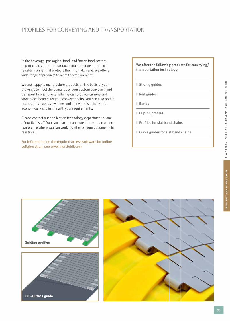
CH
AIN
, B
ElT
, A
ND
SlI
DIN
G G
UID
ES
CH
AIN
RA
CK
S /
PR
OFI
lES
FO
R C
ON
VE
yIN
G A
ND
TR
AN
SP
OR
TAT
ION
In the beverage, packaging, food, and frozen food sectors in particular, goods and products must be transported in a reliable manner that protects them from damage. We offer a wide range of products to meet this requirement.
We are happy to manufacture products on the basis of your drawings to meet the demands of your custom conveying and transport tasks. For example, we can produce carriers and work piece bearers for your conveyor belts. you can also obtain accessories such as switches and star wheels quickly and economically and in line with your requirements.
Please contact our application technology department or one of our field staff. you can also join our consultants at an online conference where you can work together on your documents in real time.
For information on the required access software for online collaboration, see www.murtfeldt.com.
PrOFILES FOr cOnVEyInG AnD TrAnSPOrTATIOn
We offer the following products for conveying/transportation technology:
Sliding guides
Rail guides
Bands
Clip-on profiles
Profiles for slat band chains
Curve guides for slat band chains
Guiding profiles
full-surface guide
95
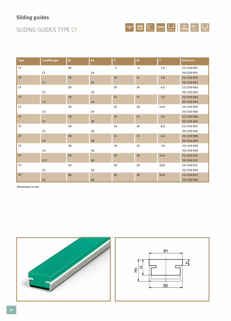
type c profile type B1 B2 h hc h article no.
CF 20 5 6 1.0 211 010 001
C1 24 351 020 001
CF 20 10 11 5.8 211 010 002
C1 24 351 020 001
CF 20 10 14 4.0 211 010 003
C3 20 351 020 003
CF 20 14 17 7.0 211 010 004
C3 20 351 020 003
CF 20 16 20 10.0 211 010 005
C3 20 351 020 003
CF 28 10 15 3.0 211 010 006
C5 28 351 020 005
CF 28 14 18 6.0 211 010 007
C5 28 351 020 005
CF 38 12 22 4.0 211 010 008
C9 38 351 020 009
CF 38 18 25 7.0 211 010 009
C9 38 351 020 009
CF 60 20 30 10.0 211 010 010
C12 60 351 020 012
CF 50 18 20 10.0 211 010 011
C4 50 351 020 004
CF 80 18 20 10.0 211 010 012
C6 80 351 020 006
SLIDInG GuIDES TyPE cF
sliding guides
Dimensions in mm
96

CH
AIN
, B
ElT
, A
ND
SlI
DIN
G G
UID
ES
rail profile delivery form delivery length in mm production method original Material”s”® article no.
profile 2000 milled green 211 210 001
C3 2000 351 020 003
Mushroom profile profile 2000 milled black antistatic 211 210 002
HR 2020 C3 2000 351 020 003
profile 2000 extruded green 211 210 003
C3 2000 351 020 003
rAIL GuIDESas insertion and clip profiles
CH
AIN
, B
ElT
, A
ND
SlI
DIN
G G
UID
ES
SlI
DIN
G G
UID
ESDimensions in mm Extruded profiles made of Material ”S”® Black are not antistatic.
* For milled profiles. Tolerances as per DIN 16941 for extruded profiles.
*
here, we present a small selection of our wide range of profiles for exemplary purposes. For our full range, see www.murtfeldt.com.
Mushroom profile hr 2020 snap on 9.5 square clip-on guides
97

Width (B) x thickness (s) article no.
15 x 3 171 010 007
18 x 3 171 010 008
20 x 3 171 010 009
22 x 3 171 010 010
25 x 3 171 010 011
30 x 3 171 010 012
35 x 3 171 010 013
40 x 3 171 010 014
45 x 3 171 010 016
50 x 3 171 010 017
60 x 3 171 010 019
70 x 3 171 010 020
80 x 3 171 010 021
90 x 3 171 010 023
100 x 3 171 010 024
111 x 3 171 010 025
Width (B) x thickness (s) article no.
20 x 4 171 010 026
25 x 4 171 010 027
30 x 4 171 010 028
40 x 4 171 010 030
50 x 4 171 010 032
Bands made from original Material ”s”®
Width (B) x thickness (s) article no.
15 x 5 171 010 034
18 x 5 171 010 035
20 x 5 171 010 036
22 x 5 171 010 037
25 x 5 171 010 038
30 x 5 171 010 039
35 x 5 171 010 040
40 x 5 171 010 041
45 x 5 171 010 042
50 x 5 171 010 043
60 x 5 171 010 044
BAnDS
Murtfeldt plastic bands are ideally suited for transporting sensitive goods. They are available in three standard sizes. Intermediate and special dimensions are available on request.
We are happy to advise you on the correct choice of band. Please contact us.
design
· Either in Original Material ”S”® Green or Original Material ”S”® Black Antistatic
· On request: Pre-treatment in the form of scraping and flaming on one side for later adhesion
special designs
· 6, 8 and 10mm in widths of between 10 and 60mm
applications
· Beverage, packaging, food, and frozen food sectors
special properties
· Extremely good wear resistance· high shock and impact resistance
* Tolerances: Thickness ± 0.1 / width ± 0.5. Roll length on request
98

CH
AIN
, B
ElT
, A
ND
SlI
DIN
G G
UID
ES
BA
ND
S /
SlI
P-O
N P
RO
FIlE
S
SLIP-On PrOFILES
for flat steel, 30 ~ 3 milled/extruded for flat steel, 40 ~ 8 milled
plastic l profile for flat steel, 40 ~ 8 extruded plastic l profile for flat steel, 40 ~ 10 milled
plastic l profile for flat steel, 40 ~ 10 extruded plastic l profile for flat steel, 50 ~ 6 milled
plastic l profile for flat steel, 50 ~ 6 extruded plastic l profile for flat steel, 40 ~ 8 milled
here is a small selection of our extensive range of profiles. View our complete range at www.murtfeldt.com.
* For milled profiles. Tolerances as per DIN 16941 for extruded profiles.99

PrOFILES FOr SLAT BAnD chAInS
profile roll length (in m) production method original Material”s”® article no.
l profile 20 x 5 35 milled green 211 310 034
l profile 20 x 5.5 50 extruded green 211 310 044
l profile 20 x 6 45 milled green 211 310 035
l profile 25 x 6 45 milled green 211 310 036
profil roll length (in m) production method original Material”s”® article no.
Bridge centre profile 40 x 7,5 50 extruded green 211 310 043
Bridge centre profile 45 x 15 6 extruded green 211 310 002
profile roll length (in m) production method original Material”s”® article no.
slide profile type u 45 x 6 35 milled green 211 310 037
centre profile 40 x 6 35 milled green 211 310 033
centre profile 40 x 6 50 extruded green 211 310 042
centre profile 40 x 5.5 50 extruded green 211 310 001
l profile 20 x 5,5l profile 20 x 5
Bridge centre profile 40 x 7.5
slide profile type u 45 x 6
l profile 20 x 6
Bridge centre profile 45 x 15
centre profile 40 x 6
l profile 25 x 6
centre profile 40 x 5.5
Dimensions in mm Extruded profiles made of Material ”S”® black are not antistatic.* For milled profiles. Tolerances as per DIN 16941 for extruded profiles.
5.5
100

CH
AIN
, B
ElT
, A
ND
SlI
DIN
G G
UID
ES
PR
OFI
lES
FO
R S
lA
T B
AN
D C
HA
INS
profile roll length (in m) production method original Material”s”® article no.
flat clamping profile 21 x 9 50 extruded green 211 310 004
flat clamping profile 26 x 11.8 50 extruded natural 211 310 039
Band profile roll length (in m) production method original Material”s”® article no.
l clamping profile 21 x 11 50 extruded green 211 310 005
l clamping profile 22 x 11 65 extruded green 211 310 041
l clamping profile 26 x 14.8 30 extruded natural 211 310 040
profile roll length (in m) production method original Material”s”® article no.
clamping u profile 6,3 x 8,7 50 extruded natural 211 310 007
t clip-on profile 40 x 20,5 2 milled green 211 310 030
Z profile 20 x 8 35 milled green 211 310 031
50 extruded green 211 310 038
flat clamping profile 21 x 9
clamping u profile 6.3 x 8.7
l clamping profile 21 x 11
t clip-on profile 40 x 20.5
l clamping profile 22 x 11
flat clamping profile 26 x 11.8
Z profile 20 x 8
l clamping profile 26 x 14.8
PrOFILES FOr SLAT BAnD chAInS
101

curVE GuIDES FOr SLAT BAnD chAInSMade-to-measure or off the shelf
Steel slat-band chains are preferable for the transport of bottles and components, like coupling components, bearings or gears. To significantly reduce abrasion as well as back-ground noise when handling these components, Murtfeldt recommends the use of plastic curve guides. These guides are ideal for the transport of sensitive products, avoiding breakage of glass bottles, preventing crushing with dairy products and avoiding scratching with PET bottles.
These curve guides form part of Murtfeldt‘s standard range. however, Murtfeldt‘s capacity to produce curve guides tailored to the customers‘ specific requirements is even greater.
102

CH
AIN
, B
ElT
, A
ND
SlI
DIN
G G
UID
ES
CU
RV
E G
UID
ES
FO
R S
lA
T B
AN
D C
HA
INS
/ D
ES
IGN
QU
ES
TIO
NN
AIR
E
curVE GuIDES FOr SLAT BAnD chAInS
Our production plant is state of the art and professionally set up for the production of individual TAB, dovetail and magne-tic curve guides. We can make your detailed requirements a reality. Download the TAB design questionnaire below on our website, as well as the questionnaires for dovetail and magne-tic curve guides.
further questionnaires are available to download at www.murtfeldt.com/services/design-questionnaires/
Please use the questionnaire to provide us with the necessary technical data or get in touch with our application engineers who will be pleased to help you immediately with producing the necessary drawings.
yOur cOnTAcT DETAILS TEAM APPLIcATIOn TEchnOLOGy
name, first name We are happy to provide free, non-binding advice on selecting the suitable design and material of your curve guide.
Please send the fill-out form to: [email protected]
or print it out and send it by fax to: Fax 0049 (0) 231 20609-518
company
Postal code, city
Street
Phone
Fax
DIMEnSIOnS In MM
H r1 Segment angle
B r2 Length GE
b1 r3 a
b2 r4
h1 r5
h2 r6
BAuArT
countersunk hole yES nO anzahl /
Thread insert yES nO anzahl /
Material for curve guide
Type of chain
rEMArkS
shown with taB guide, with and without straight ends
103

GuIDES FOr MODuLAr BELTS
conveyor belts are highly modular and can even be integrated into the most complex systems. Murtfeldt Plastics produces guides for modular belts, manufactured from highly wear-resistant, low-friction plastics like Original Material ”S”® green, ”S”® plus+ LF or ”S”® plus+ ESD. These guides are used as solid sliding bases, and also as cF profiles, slip-on profiles or sliding guides with tongue and groove in a straight or an arrow-shaped arrangement. you will find our solutions in almost all sectors, in the packaging industry, as well as in filling plants or in the automotive sector.
at a glance: Guides for modular chains
Flat profiles
Profiles with hold-down clips
Slip-on profiles (c for flat steel)
cF profiles
Flat profiles with tongue and groove
V-shaped flat profiles
Solid guides (based on a drawing)
Materials
Original Material ”S”® plus+ LF
Original Material”S”® plus+ LF ESD
Original Material”S”® plus+ ESD
Original Material”S”® plus+ Bright ESD
Original Material ”S”® black antistatic
Benefits
Low sliding friction Excellent wear resistance
no static charge depending on the design
Slip-on profiles
cF profiles
Flat profiles with hold-down clips104

GuIDES FOr MODuLAr BELTS
Flat profiles with tongue and groove
Arrow shape
Solid sliding base
CH
AIN
, B
ElT
, A
ND
SlI
DIN
G G
UID
ES
GU
IDE
S F
OR
MO
DU
lA
R B
ElT
S
105

106

tensIonIng systems
107

TEnSIOnInG SySTEMS – TABLE OF cOnTEnTS
Table of contents 108
Introduction 109
Function, Principles, handling 110
Optical control Displays 111
Spann-Box® Overview 112 – 113
Signs and Symbols 113
The correct choice of chain Tensioner 114
Selection Table for Tensioning Systems 115 – 116
Graphical Depiction of Installation Examples 117
Mounting Brackets for Spann-Box® Systems 118 – 119
Inductive Switches 120
chain Tensioners for roller chains as per DIn 8187 121 – 133
Mini-Tensioner, Spann-Boy®TS, Spann-Box® size 0, Spann-Box® size 30, Spann-Box® size 1, Spann-Box® size 2
Automatic Belt Tensioners 134 – 139
Spann-Boy®TS, Spann-Box® size 0, Spann-Box® size 1, Spann-Box® size 1 Type Sr-l, Spann-Box® size 1 Type Sr-S
Special Tensioners 140 – 141
108

TE
NS
ION
ING
Sy
ST
EM
STA
BlE
OF
CO
NT
EN
TS /
IN
TR
OD
UC
TIO
N
TEnSIOnInG SySTEMSfor chains and belts
chains and belts are important wearing parts in many plants and machines. Since they are constantly moving, the stresses to which they are subjected are particularly high. Belts require pretensioning – chain links elongate and run increasingly less smoothly.
Murtfeldt tensioning systems keep chains and belts reliably tensioned, thus increasing their lifetime. They are tried-and-tested following decades of use around the world. Our experience with these systems enables us to provide you with optimum advice and to always offer the best possible solution for your needs.
Wide range – extensive inventory
Thanks to our variety of different tensioning systems, we are able to quickly and accurately meet practically any requirements. If you require an individual solution, our free- of-charge, non-binding consulting services are sure to help.
one more thing: We supply all tensioning systems with a declaration of installation in line with the Machinery directive ec 2006/42/ec.
Advantages of our tensioning systems
Smooth chain movement
Reduction in wear on chain links
and drive sprockets Reduction in working noise
Automatic adjustment
Compensation for chain and belt
elongation Use as chain and belt monitors
Direction change for chain and belt
drives Small installation size
Simple assembly
Quick and safe recognition of need
to adjust system thanks to optical control display
109

Our tensioning systems are free-running and resilient. As a result, they do not function as rigid deflectors when stressed. This avoids excessive contact pressure. Our systems aim to keep the overall force on the slack strand – resulting from the weight of the chain and the centrifugal force – under control. The ideal installation position is right behind the drive sprocket in order to keep the length of the slack strand that needs to be tensioned as short as possible.
tried-and-tested quality
The stable design of the steel housing makes our tensioning systems resistant to high mechanical loads. Our housings and tensioning systems are galvanized, which provides protection against corrosion. A plastic lacquer makes the surface impact and scratch resistant. In addition, we offer a stainless steel range for particularly high corrosion resistance requirements. All slide profiles are made of Original Material ”S”®.
Installation
Special holding mechanisms initially hold back the spring action. When these retainers are released following the installation, the tensioning pressure is released in a targeted manner.
tension force regulation
For all Murtfeldt tensioning systems, you can choose either light or heavy tensioning pressure. Depending on the type, the tensioners have one, two, or three springs. you decide how many springs you want to use. This enables the optimum application of pressure onto a chain or belt running on the profile.
FuncTIOn, PrIncIPLES, hAnDLInG
Employees from our application technology department are constantly available to make sure that we are able to provide the best product to meet your requirements.
The weight on the return side of the chain that is to be tensioned should not be greater than the force of a spring already 50 % released.
optimum installation position
use at extreme temperatures
If you choose the correct material, you can also use our tensioning systems in otherwise problematic temperature ranges:normal steel springs: -10 to +170o cStainless steel springs: -40 to +200o c
the red dot on the spann-Box® means “heavy tensioning force”.
110

Murtfeldt Spann-Box® systems generally have a coloured scale. This enables you to determine the tensioning state of the chain at a glance. The display is as easy to understand as possible:
Green
The chain tensioner is working in the “green range”. The tensioning force is providing an ideal, smooth running movement.
yellow
The tensioning force is not ideal but is still sufficient.
red
The chain tensioner needs to be adjusted. The tensioning force on the chain is too low for a smooth and reliable running movement.
The chain has to be replaced if it is not possible to sufficiently adjust the chain tensioner using any of the available adjustment options.
OPTIcAL cOnTrOL DISPLAyS
TE
NS
ION
ING
Sy
ST
EM
SFU
NC
TIO
N,
PR
INC
IPlE
S,
HA
ND
lIN
G |
OP
TIC
Al
CO
NT
RO
l D
ISP
lA
yS
111

OVErVIEW OF SPAnn-BOX® TyPES
Mini-tensioner page 121
Spann-Box® size 0 page 124
Spann-Boy® TS with arc segment profile – page 122
Spann-Boy® TSwith sprocket – page 123
Spann-Box® size 30page 125
Spann-Box® size 1 with arc segment profile – page 126
Spann-Box® size 1 with semi-circular profile – page 127
Spann-Box® size 1 with sprocketType K-l – page 129
Spann-Box® size 1 with sprocket Type K-S – page 129
Spann-Box® size 2 with return profile – page 132 Spann-Box® size 2 with block profile – page 133
chain tensioners
Spann-Box® size 2 with semi-circular profile – page 131Spann-Box® size 2 with arc segment profile– page 130
Spann-Box® size 1 with return profile – page 128
112

SIGnS AnD SyMBOLS
Spann-Box® size 0 page 136
Spann-Boy® TStensioning roller – page 135
Spann-Box® size 1 belt tensioner with tensioning roller at top – page 137
Spann-Box® size 1 with tensioning roller type Sr-l – page 138
Spann-Box® size 1 with tensioning roller type Sr-S – page 139
Belt tensioners
features and properties of tensioning systems
One pre-tensioned compression spring, tension distance specification in mm
Two pre-tensioned compression springs, tension distance specification in mm
Three pre-tensioned compression springs, tension distance specification in mm
Further adjustment possible: Adjustment range in mm once original tension distance has been used (value for size 1 and size 2 if using mounting bracket)
Plastic housing
Steel housing (also stainless steel)
Track profile for all large chains
u profile for chains up to specified overall width in mm
TE
NS
ION
ING
Sy
ST
EM
SO
VE
RV
IEW
OF
SP
AN
N-B
OX
® T
yP
ES
113

ThE cOrrEcT chOIcE OF chAIn TEnSIOnEr
Smooth running is a decisive factor for the long lifetime of a chain. We therefore recommend the use of a chain tensioner with a slide profile. Advantage: Protects the chain links and provides a quieter, safer movement.
We are happy to provide detailed advice if you inform us of the required criteria. Our Web site at www.murtfeldt.com contains a design questionnaire that you can use to enter all required data.
IMPORTANT CRITERIA WHEN SELECTING THE BEST CHAIN TENSIONER FOR YOUR NEEDS Axis-centre distances of sprockets
Chain design
Constant/changing running direction
Chain speed
Chain lubrication
Operating time and intensity
Risk of contamination
Environmental temperature
Chemical influences
114

EXPLAnATIOn OF SyMBOLSprofiles symbols forselection tables
1) It is possible to use several types of SPANN-BOX ® alongside each other with duplex or triplex chains.
2) Slide profile or return pulley with U-profile. simplex chain
Chain Pitch inch MINI-TENSIONER
SPANN-BOY® TS with arc segment profile
SPANN-BOY® TS with sprocket
SPANN-BOX®
size 0
SPANN-BOX®
size 30
SPANN-BOX®
size 1
SPANN-BOX®
size 2
MINI-TENSIONER
SPANN-BOY® TS with arc segment profile
SPANN-BOY® TS withsprocket
SPANN-BOX®
size 0
SPANN-BOX®
size 30
SPANN-BOX®
size 1
SPANN-BOX®
size 2
SPANN-BOY® TS
SPANN-BOX®
size 0
SPANN-BOX®
size 30
SPANN-BOX®
size 1
SPANN-BOX®
size 2DIN ISO mm
Unspecified chains with a width of up to 15 mm 2)
2) 2) 2) 2) 2) 2) 2) 2)
06B 9,525 ³⁄8
2) 2) 2) 2)
08B 12,7 ¹⁄2
10B 15,875 ⁵⁄8
12B 19,05 ³⁄4
16B 25,4 1
20B 31,75 1 ¹⁄4
24B 38,1 1 ¹⁄2
1)
28B 44,45 1 ³⁄4
1) 1)
32B 50,8 2
1) 1)
40B 63,5 2 ¹⁄2
1) 1)
48B 76,2 3
1) 1)
SELEcTIOn TABLE FOr chAIn TEnSIOnErS
Arc segment profile· Slide profile shape with optimum mechanical properties
· Simultaneous contact with several rollers· Optimum chain protection
Return profile· 180° change of direction· The 180° change of direction per-mits the dual use of longer tension distances.
115

Roller/sprocket· For small changes of direction· For high chain speeds ( > 1 m/s)
duplex chain triplex chain
Chain Pitch inch MINI-TENSIONER
SPANN-BOY® TS with arc segment profile
SPANN-BOY® TS with sprocket
SPANN-BOX®
size 0
SPANN-BOX®
size 30
SPANN-BOX®
size 1
SPANN-BOX®
size 2
MINI-TENSIONER
SPANN-BOY® TS with arc segment profile
SPANN-BOY® TS withsprocket
SPANN-BOX®
size 0
SPANN-BOX®
size 30
SPANN-BOX®
size 1
SPANN-BOX®
size 2
SPANN-BOY® TS
SPANN-BOX®
size 0
SPANN-BOX®
size 30
SPANN-BOX®
size 1
SPANN-BOX®
size 2DIN ISO mm
Unspecified chains with a width of up to 15 mm 2)
2) 2) 2) 2) 2) 2) 2) 2)
06B 9,525 ³⁄8
2) 2) 2) 2)
08B 12,7 ¹⁄2
10B 15,875 ⁵⁄8
12B 19,05 ³⁄4
16B 25,4 1
20B 31,75 1 ¹⁄4
24B 38,1 1 ¹⁄2
1)
28B 44,45 1 ³⁄4
1) 1)
32B 50,8 2
1) 1)
40B 63,5 2 ¹⁄2
1) 1)
48B 76,2 3
1) 1)
Block profile · Suitable for particularly heavy chains and high mass forces· Slide profile and tension core made from a single piece· no screw connections· Excellent stability· 300 mm slide profile ensures support for many rollers with
chains with large chain pitches
Semi-circular profile· For 90° deflection· contact with only very
few chain rollers· recommended where
space is at a premium
116

TE
NS
ION
ING
Sy
ST
EM
SS
ElE
CT
ION
TA
BlE
FO
R C
HA
IN T
EN
SIO
NE
RS
/ G
RA
PH
ICA
l D
EP
ICT
ION
OF
INS
TAll
AT
ION
EX
AM
PlE
S
GrAPhIcAL DEPIcTIOn OF InSTALLATIOn EXAMPLES
Popular but non-optimal arrangement, tension distance not used efficiently
Optimum, extremely efficient chain support/tensioning
180° return profile. This arrangement allows a particularly long chain length to be accommodated.
return/tensioning stationIf the running direction changes, we recommend using two Spann-Box® units near to the drive.
Omega tensioning station – ready-to-install system
117

MOunTInG BrAckETS FOr SPAnn-BOX® SySTEMS
We offer various mounting brackets to make assembly more easy. They provide additional modification/adjustment flexibility. Elongated mounting holes allow easy adjustment if the normal tension distance has already been used up. Alignment errors can be corrected by side movement.
the ideal assembly aid
corresponding size adjustment range Material article no.
1 67 mm St 37 powder-coated 281 090 001
2 75 mm St 37 powder-coated 281 090 002
1 67 mm 1.4301 (V2A) 281 090 029
2 75 mm 1.4301 (V2A) 281 090 030
0 – 1.4301 (V2A) incl. screws 281 090 087
30 – 1.4301 (V2A) incl. screws 281 090 088
We are happy to provide detailed assembly instructions for all our systems. Simply contact us or see our website at www.murtfeldt.com.
Size 1 and 2
The top numbers are for size 1 and the bottom numbers are for size 2.
118

TE
NS
ION
ING
Sy
ST
EM
SM
OU
NT
ING
BR
AC
KE
TS F
OR
SP
AN
N-B
OX
® S
yS
TE
MS
97
115
9.2
5
16.
5
8.5
5
5 45
45
R4
R4
16.
5
8.5
97
60
30
R4
9.2
5
155
11
10.
5
19
180
90
R4 19
10.
5
30
R4
50
50
5
R4
80
20°
6.5
52
94
38
114
134
19
16
8.5 14
2.5
2.5
40
65max. R2.5
80
20°
6,5
52
94
38
114
134
19
16
8,5 14
2,5
2,5
40
65max. R2,5
Spann-Box® size 30
116
40
6.
5
43
78
68°
max. R2.5
2.5
36
55
12
8.5
97
12
13
19
23.
5
38
22.5°
6.5
46
50
2
28
60
2
max. R2
70
90
13.5
8
8.5 14
Spann-Boy® TS Spann-Box® size 0
Spann-Box® size 1 (standard) Spann-Box® size 1– alternative fixing
Spann-Box® size 2
221,34
168
,17
117 8,17
57,
56
20°
54,
27
8,5
+ 0,1
0
15
8,5 + 0,10
15
8 + 0,20
87
97
156,34
31,
17
17,
5
63,
67
53
95
59,
67
36,
1 1
17,9
8
120
,08
Z
DOWN 90° R 4 DOWN 90° R 4
DO
WN
90°
R 4
DOWN 90° R 4
DO
WN
90°
R 4
t=2
DETAIL Z MAßSTAB 2 : 1
Eckenradius erlaubt
50
122
129
1:2
Abwicklung
-Kanten manuell abrunden
0 15.04.11 Ullenboom
Zust. Änderung Datum Name
D
E
F
C
1 2 3 4
B
A
321 5
C
D
4 6 7 8
A
B
M-105053-0000
Szymlek 14.04.2011
0Ersatz für:entstanden aus:
Index:
-
-Artikel-Nr.:
Gep.
Allgemeintoleranzen fürLängenmaße nachDIN ISO 2768 mittel
Gez.
Name Datum
Material:
Kunden-Nr.:
Benennung:
Zeichnungs Nr.
Maßstab: 1:1
Blatt 1 von 1
A31.4301 (V2A)
Gewicht: 0.39 kg
Befestigungswinkel
Murtfeldt Kunststoffe GmbH & Co. KGHeßlingsweg 14-1644309 DortmundTel. +49-231-20609-0 ● Fax. +49-231-251021www.murtfeldt.de
14.04.2011Ullenboom
Die Zeichnung ist unser Eigentum.Sie darf weder vervielfältigt noch an Dritte weitergegeben werden.
für Spannbox_Gr1
221,34
168
,17
117 8,17
57,
56
20° 5
4,27
8,5
+ 0,1
0
15
8,5 + 0,10
15
8 + 0,20
87
97
156,34
31,
17
17,
5
63,
67
53
95
59,
67
36,
1 1
17,9
8
120
,08
Z
DOWN 90° R 4 DOWN 90° R 4
DO
WN
90°
R 4
DOWN 90° R 4
DO
WN
90°
R 4
t=2
DETAIL Z MAßSTAB 2 : 1
Eckenradius erlaubt
50
122
129
1:2
Abwicklung
-Kanten manuell abrunden
0 15.04.11 Ullenboom
Zust. Änderung Datum Name
D
E
F
C
1 2 3 4
B
A
321 5
C
D
4 6 7 8
A
B
M-105053-0000
Szymlek 14.04.2011
0Ersatz für:entstanden aus:
Index:
-
-Artikel-Nr.:
Gep.
Allgemeintoleranzen fürLängenmaße nachDIN ISO 2768 mittel
Gez.
Name Datum
Material:
Kunden-Nr.:
Benennung:
Zeichnungs Nr.
Maßstab: 1:1
Blatt 1 von 1
A31.4301 (V2A)
Gewicht: 0.39 kg
Befestigungswinkel
Murtfeldt Kunststoffe GmbH & Co. KGHeßlingsweg 14-1644309 DortmundTel. +49-231-20609-0 ● Fax. +49-231-251021www.murtfeldt.de
14.04.2011Ullenboom
Die Zeichnung ist unser Eigentum.Sie darf weder vervielfältigt noch an Dritte weitergegeben werden.
für Spannbox_Gr1
119

If a chain has excessive elongation or a break, critical damage can occur. Our chain and belt monitors track the production process and trigger the automatic shutdown of the machine if malfunctions occur. For this purpose, a mechanical limit switch or contact-free inductive switch is integrated into your chain or belt tensioner.
Both individual and reliable
Switch design requirements can vary greatly. Please contact us for more information. We will design the best solution for your requirements.
chAIn AnD BELT MOnITOrS
Inductive switches for spann-Box®
Alternatively, a contact-free inductive switch can be used. This makes sense if there is a risk of explosion or contamination. concerns about wear might also result in the use of an inductive switch. Inductive switches can be used for Spann-Box® size 1 and 2. Special models and designs in stainless steel are available on request.
120

TE
NS
ION
ING
Sy
ST
EM
SC
HA
IN A
ND
BE
lT M
ON
ITO
RS
/ C
HA
IN T
EN
SIO
NE
RS
FO
R R
Oll
ER
CH
AIN
S
MInI-TEnSIOnEr
dIn 8187 chain no. light tension force article no.
heavy tension forcearticle no.
<06B-1 (U-Profil) 281 050 001 281 050 002
06B-1 281 050 003 281 050 004
08B-1 281 050 009 281 050 010
10B-1 – 281 050 011
05B-2 281 050 005 281 050 006
06B-2 281 050 007 281 050 008
max. 200
Installation variant
Special and stainless steel designs on request
tensioning pressure
· choice of light or heavy spring force
chain guide
· Track profile for 06B-1, 08B-1 and duplex chains
attachment
· Screws on bracket base
axis-centre distance
· Max. 200mm recommended
with arc segment profile10 mm16 mm
dIn 8187 chain no.
pitch in mm
pitch in inch
simplex duplex triplex
M 06B – –
06B 9,525 D/i
08B 12,7 -
Tension forceLight Heavy
2 springs 19 – 13 N 85 – 58 N
Tension distance 16 mm 16 mm
MINI-TENSIONER
The smallest automatic chain tensioner in our range, the mini-tensioner is targeted for use with smaller chains with a chain pitch of up to - .
chain tensioners for roller chains per dIn 8187
121

Light Heavy
Tension force Spann-Boy® TS1 released spring 58 – 32 N 132 – 60 N
2 released springs 190 – 96 N (extra heavy)
Tension distance 40 mm 40 mm
spann-Boy® ts
If the space beneath the chain is not large enough for a traditional tensioning system, Spann-Boy® TS can be used. They are installed near to the chain and thus require considerably less space.
design
Our Spann-Boy® TS models are made from robust steel. The focus is on achieving a long lifetime and reliability. There are two different variants: With an arc segment profile or with a sprocket. Spann-Boy® TS has two pre-tensioned
springs. They can be released separately and provide three different tension pressure settings. The bore holes in the housing make assembly easier and provide more scope for adjustment once the original tension distance has been used up.
SPAnn-BOy® TS
dIn 8187 chain no. B a article no.standard design
article no.stainless steel
≤ 06B-1 (U-Profile) 20 10,0 281 060 001 282 060 002
08B-1 20 16,5 281 060 003 282 060 004
10B-1 20 15,6 281 060 005 282 060 006
12B-1 20 14,8 281 060 007 282 060 008
06B-2 20 7,5 281 060 009 282 060 010
08B-2 32 15,2 281 060 011 282 060 012
10B-2 32 11,3 281 060 013 282 060 014
05B-3 20 7,4 281 060 015 282 060 016
06B-3 32 9,4 281 060 017 282 060 018
Special designs on request
with arc segment profile
applications · For applications with restricted free space beneath the chain. 40mm are sufficient.
tensioning pressure
· Spann-Boy® TS has one light and one heavy pressure spring that can be released together or separately depen-ding on the required tension pressure.
attachment
· Installed next to the chain· Bore holes in the housing (for matching
fastening brackets refer to pages 118 - 119)
15 mm 60 mm40 mm
three tension pressure settings
122

TE
NS
ION
ING
Sy
ST
EM
S C
HA
IN T
EN
SIO
NE
RS
FO
R R
Oll
ER
CH
AIN
S
SPAnn-BOy® TS
dIn 8187 chain no. number of teeth article no. standard design
06B-1 20 281 260 002
06B-1 21 281 260 003
06B-1 23 281 260 004
08B-1 16 281 260 005
08B-1 17 281 260 006
08B-1 18 281 260 007
10B-1 14 281 260 008
10B-1 15 281 260 009
10B-1 16 281 260 010
10B-1 17 281 260 011
12B-1 13 281 260 012
12B-1 15 281 260 013
12B-1 16 281 260 014
12B-1 17 281 260 015
Special and stainless steel designs on request
applications
· For applications with restricted free space beneath the chain
· high chain speeds ( > 1m/s)· Small return radii
tensioning pressure
· Spann-Boy® TS has one light and one heavy pressure spring that can be released together or separately depending on the required tension pressure.
attachment
· Installed next to the chain· Bore holes in the housing (for matching
fastening brackets refer to pages 118 - 119)
with sprocket60 mm40 mm
123

spann-Box® sIZe 0
dIn 8187 chain no. light tension force article no.
heavy tension forcearticle no.
≤06B-1 (U-Profile) 281 000 001 281 000 002
08B-1 281 000 003 281 000 004
10B-1 281 000 003 281 000 004
12B-1 281 000 005 281 000 006
06B-2 281 000 007 281 000 008
08B-2 281 000 009 281 000 010
10B-2 281 000 011 281 000 012
Special designs on request
applications
· restricted installation space· Environments with a risk of corrosion· chain drives with a pitch of up to :]
tensioning pressure
· choice of light or heavy spring force· Lock pin in base of housing
attachment
· Installed underneath the chain· Bore holes in the housing (for matching
fastening brackets refer to pages 118 - 119)
The Spann-Box® size 0 is the smallest in our range. It is used where installation spaces are very restricted. The plastic housing means there is no risk of corrosion.
SPAnn-BOX® SIZE 0 with semi-circular profile
15 mm 25 mm40 mm
stainless steel screws and springs
attachment
Light Heavy
Tension force 1 spring 58 – 32 N 132 – 60 N
Tension distance 40 mm 40 mm
124

TE
NS
ION
ING
Sy
ST
EM
S C
HA
IN T
EN
SIO
NE
RS
FO
R R
Oll
ER
CH
AIN
S
Spann-Box® Size 30
dIn 8187 chain no. B mm light tension force article no.
heavy tension forcearticle no.
≤06B-1 (U-Profile) 20 281 030 001 281 030 002
08B-1 20 281 030 003 281 030 004
10B-1 20 281 030 005 281 030 006
12B-1 20 281 030 007 281 030 008
16B-1 20 281 030 009 281 030 010
05B-2 20 281 030 011 281 030 012
06B-2 20 281 030 013 281 030 014
08B-2 20 281 030 015 281 030 016
10B-2 25 281 030 017 281 030 018
12B-2 30 281 030 019 281 030 020
05B-3 20 281 030 021 281 030 022
06B-3 25 281 030 023 281 030 024
08B-3 30 281 030 025 281 030 026
10B-3 40 281 030 027 281 030 028
12B-3 45 281 030 029 281 030 030
Special designs on request
Spann-Box® size 30 provides high quality at the same time as being economically priced. The robust plastic housing gives high resistance to corrosion.
SPAnn-BOX® SIZE 30with arc segment profile
Light Heavy
Tension force
1 released spring 58 – 32 N 132 – 60 N
2 released springs 116 – 64 N 264 – 120 N
3 released springs 174 – 96 N 396 – 180 N
Tension distance 40 mm 40 mm
applications
· Environments with a risk of corrosion· no high mechanical stresses
tensioning pressure
· choice of light or heavy spring force
attachment
· Installed underneath the chain· Bore holes in the housing (for matching
fastening brackets refer to pages 118 - 119)
15 mm 40 mm 30 mm
attachment
stainless steel screws and springs
three tension pressure settings
125

SPANN-BOX® SIzE 1
Spann-Box® size 1 is available in several variants. The robust design with its steel housing guarantees durability and reliable operation.
We offer a total of five different designs to meet individual requirements.
reverse operation
If the running direction changes, we recommend using the appropriate Spann-Box® size with a long housing. We deliver this variant with heavy tension force.
Light Heavy
Tension force
1 released spring 58 – 32 N 132 – 60 N
2 released springs 116 – 64 N 264 – 120 N
3 released springs 174 – 96 N 396 – 180 N
Tensioning distance 40 mm 40 mm
Clamp dimensions (...) for long housing
dIn 8187 chain no.
Bmm
short hou-sing, light tension force article no.
short hou-sing, heavy tension force article no.
long hou-sing, heavy tension force article no.
stainless steel, heavy tension force, short housing article no.
stainless steel, heavy tension force, long housing article no.
≤06B-1 (U-Profile)
20 281 010 001 281 010 002 281 010 202 282 010 002 282 010 202
08B-1 20 281 010 003 281 010 004 281 010 204 282 010 004 282 010 204
10B-1 20 281 010 005 281 010 006 281 010 206 282 010 006 282 010 206
12B-1 20 281 010 007 281 010 008 281 010 208 282 010 008 282 010 208
16B-1 20 281 010 009 281 010 010 281 010 210 282 010 010 282 010 210
20B-1 20 281 010 011 281 010 012 281 010 212 282 010 012 282 010 212
06B-2 20 281 010 013 281 010 014 281 010 214 282 010 014 282 010 214
08B-2 20 281 010 015 281 010 016 281 010 216 282 010 016 282 010 216
10B-2 25 281 010 017 281 010 018 281 010 218 282 010 018 282 010 218
12B-2 30 281 010 019 281 010 020 281 010 220 282 010 020 282 010 220
16B-2 45 281 010 021 281 010 022 281 010 222 282 010 022 282 010 222
06B-3 25 281 010 023 281 010 024 281 010 224 282 010 024 282 010 224
08B-3 30 281 010 025 281 010 026 281 010 226 282 010 026 282 010 226
10B-3 40 281 010 027 281 010 028 281 010 228 282 010 028 282 010 228
12B-3 45 281 010 029 281 010 030 281 010 230 282 010 030 282 010 230
Special designs on request
tensioning pressure
· choice of light or heavy spring force
attachment
· Installed underneath the chain· Bore holes in the housing (for matching
fastening brackets refer to pages 118 - 119)
SPAnn-BOX® SIZE 1with arc segment profile
15 mm 40 mm 67 mm
three tension pressure settings
126

Clamp dimensions (...) for long housing
SPAnn-BOX® SIZE 1with semi-circular profile
dIn 8187 chain no. Bmm
short housing,light tension force article no.
short housing, heavy tension force article no.
long housing, heavy tension force article no.
stainless steel, heavy tension force, short housing article no.
stainless steel, heavy tension force, long housing article no.
06B-1 30 281 010 031 281 010 032 281 010 232 282 010 032 282 010 232
08B-1 30 281 010 033 281 010 034 281 010 234 282 010 034 282 010 234
10B-1 30 281 010 035 281 010 036 281 010 236 282 010 036 282 010 236
12B-1 30 281 010 037 281 010 038 281 010 238 282 010 038 282 010 238
06B-2 30 281 010 039 281 010 040 281 010 240 282 010 040 282 010 240
08B-2 30 281 010 041 281 010 042 281 010 242 282 010 042 282 010 242
10B-2 30 281 010 043 281 010 044 281 010 244 282 010 044 282 010 244
12B-2 30 281 010 045 281 010 046 281 010 246 282 010 046 282 010 246
06B-3 30 281 010 047 281 010 048 281 010 248 282 010 048 282 010 248
08B-3 30 281 010 049 281 010 050 281 010 250 282 010 050 282 010 250
Special designs on request
applications
· For restricted installation spaces
tensioning pressure
· choice of light or heavy spring force
attachment
· Easier assembly thanks to mounting bracket
· Bore holes in the housing (for matching fastening brackets refer to pages 118 - 119)
40 mm 67 mm
TE
NS
ION
ING
Sy
ST
EM
S C
HA
IN T
EN
SIO
NE
RS
FO
R R
Oll
ER
CH
AIN
S
127

SPAnn-BOX® SIZE 1
dIn 8187 chain no. Bmm
long housing, heavy tension force article no.
stainless steel, long housing, heavy tension force article no.
06B-1 30 281 010 051 282 010 051
08B-1 30 281 010 052 282 010 052
10B-1 30 281 010 053 282 010 053
12B-1 30 281 010 054 282 010 054
16B-1 30 281 010 055 282 010 055
06B-2 30 281 010 056 282 010 256
08B-2 30 281 010 057 282 010 257
10B-2 30 281 010 058 282 010 258
12B-2 30 281 010 059 282 010 259
06B-3 30 281 010 060 282 010 260
08B-3 30 281 010 061 282 010 261
Special designs on request
40 mm 67 mmwith 180° return profile
If the Spann-Box has been properly fit-ted, the double length of the Spann-Box‘s tension distance can be used to compen-sate for chain extension. For more examples see page 117.
tensioning pressure
· heavy spring force
attachment
· Easier assembly thanks to fastening bracket
· Bore holes in the housing (for matching fastening brackets refer to pages 118 - 119)
5.5
8.5
Tens
ion
dist
ance
128

TE
NS
ION
ING
Sy
ST
EM
S C
HA
IN T
EN
SIO
NE
RS
FO
R R
Oll
ER
CH
AIN
S
SPAnn-BOX® SIZE 1with sprocket wheel type K-l / type K-s
dIn 8187 chain no. no. of teeth type K-lheavy tension force article no.
type K-sheavy tension force article no.
06B-1 20 281 210 005 281 210 001
06B-1 21 281 210 011 281 210 022
06B-1 23 281 210 012 281 210 023
08B-1 16 281 210 014 281 210 024
08B-1 17 281 210 006 281 210 025
08B-1 18 281 210 015 281 210 002
10B-1 14 281 210 016 281 210 026
10B-1 15 281 210 017 281 210 027
10B-1 16 281 210 007 281 210 028
10B-1 17 281 210 018 281 210 003
12B-1 13 281 210 033 281 210 029
12B-1 14 281 210 019 281 210 030
12B-1 15 281 210 008 281 210 004
12B-1 16 281 210 020 281 210 031
12B-1 17 281 210 021 281 210 032
Special and stainless steel designs on request
Spann-Box® size 1 with sprocket is used where space is restricted or there are high chain speeds (> 1m/s).
applications
· high chain speeds· Small return radii· compensation for high chain elongation
tensioning pressure
· heavy spring force
attachment
· Easier assembly thanks to mounting bracket· Bore holes in the housing (for matching
fastening brackets refer to pages 118 - 119)
40 mm 67 mm
type K-l
type K-s
129
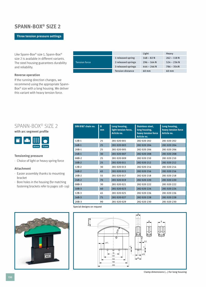
SPANN-BOX® SIzE 2
Like Spann-Box® size 1, Spann-Box® size 2 is available in different variants. The steel housing guarantees durability and reliability.
reverse operation
If the running direction changes, we recommend using the appropriate Spann-Box® size with a long housing. We deliver this variant with heavy tension force.
dIn 8187 chain no. Bmm
long housing, light tension force,article no.
stainless steel,long housing,heavy tension forcearticle no.
long housing,heavy tension forcearticle no.
12B-1 25 281 020 001 282 020 202 281 020 202
16B-1 25 281 020 003 282 020 204 281 020 204
20B-1 25 281 020 005 282 020 206 281 020 206
24B-1 30 281 020 007 282 020 208 281 020 208
08B-2 25 281 020 009 282 020 210 281 020 210
10B-2 25 281 020 011 282 020 212 281 020 212
12B-2 30 281 020 013 282 020 214 281 020 214
16B-2 45 281 020 015 282 020 216 281 020 216
20B-2 55 281 020 017 282 020 218 281 020 218
24B-2 70 281 020 019 282 020 220 281 020 220
08B-3 30 281 020 021 282 020 222 281 020 222
10B-3 40 281 020 023 282 020 224 281 020 224
12B-3 45 281 020 025 282 020 226 281 020 226
16B-3 75 281 020 027 282 020 228 281 020 228
20B-3 90 281 020 029 282 020 230 281 020 230
Special designs on request
SPAnn-BOX® SIZE 2with arc segment profile
tensioning pressure
· choice of light or heavy spring force
attachment
· Easier assembly thanks to mounting bracket
· Bore holes in the housing (for matching fastening brackets refer to pages 118 - 119)
60 mm 75 mm
Clamp dimensions (...) for long housing
Light Heavy
Tension force
1 released spring 148 – 82 N 262 – 118 N
2 released springs 296 – 164 N 524 – 236 N
3 released springs 444 – 246 N 786 – 354 N
Tension distance 60 mm 60 mm
three tension pressure settings
130

TE
NS
ION
ING
Sy
ST
EM
S C
HA
IN T
EN
SIO
NE
RS
FO
R R
Oll
ER
CH
AIN
S
SPAnn-BOX® SIZE 2with semi-circular profile
dIn 8187 chain no. Bmm
long housing,light tension force,article no.
long housing,heavy tension force,article no.
stainless steel,long housing,heavy tension force,article no.
12B-1 33 281 020 032 281 020 232 282 020 232
16B-1 33 281 020 034 281 020 234 282 020 234
08B-2 33 281 020 036 281 020 236 282 020 236
10B-2 33 281 020 038 281 020 238 282 020 238
12B-2 33 281 020 040 281 020 240 282 020 240
08B-3 33 281 020 042 281 020 242 282 020 242
10B-3 40 281 020 044 281 020 244 282 020 244
Special designs on request
applications
· For restricted installation spaces
tensioning pressure
· choice of light or heavy spring force
attachment
· Easier assembly thanks to mounting bracket
· Bore holes in the housing (for matching fastening brackets refer to pages 118 - 119)
60 mm 75 mm
Clamp dimensions (...) for long housing
131

dIn 8187 chain no. Bmm
long housing,heavy tension forcearticle no.
stainless steel,long housing,heavy tension forcearticle no.
12B-1 33 281 020 045 282 020 045
16B-1 33 281 020 046 282 020 046
20B-1 33 281 020 047 282 020 047
08B-2 33 281 020 048 282 020 048
10B-2 33 281 020 049 282 020 049
12B-2 33 281 020 050 282 020 050
08B-3 33 281 020 051 282 020 051
10B-3 40 281 020 052 282 020 052
12B-3 45 281 020 053 282 020 053
SPAnn-BOX® SIZE 2with 180° return profile
Special designs on request
With the appropriate installation, the double tension distance length can be used for chain elongation.Further instal-lation examples see page 117.
tensioning pressure
· heavy spring force
attachment
· Easier assembly thanks to mounting bracket
· Bore holes in the housing (for matching fastening brackets refer to pages 118 - 119)
60 mm 75 mm
132

TE
NS
ION
ING
Sy
ST
EM
S C
HA
IN T
EN
SIO
NE
RS
FO
R R
Oll
ER
CH
AIN
S
SPAnn-BOX® SIZE 2with block profile
dIn 8187 chain no. Bmm
long housing,heavy tension forcearticle no.
stainless steel, long housing, heavy tension forcearticle no.
24B-1 33 281 020 054 282 020 054
28B-1 33 281 020 055 282 020 055
32B-1 33 281 020 056 282 020 056
40B-1 40 281 020 057 282 020 057
48B-1 45 281 020 058 282 020 058
16B-2 45 281 020 059 282 020 059
20B-2 55 281 020 060 282 020 060
24B-2 70 281 020 061 282 020 061
16B-3 75 281 020 062 282 020 062
20B-3 90 281 020 063 282 020 063
Special designs on request
This design is ideally suited for heavy loads. It is intended for use with high dynamic forces.
design
· Slide profile and tension core made from a single piece
tensioning pressure
· heavy spring force
attachment
· Easier assembly thanks to mounting bracket
· Bore holes in the housing (for matching fastening brackets refer to pages 118 - 119)
60 mm 75 mm
133
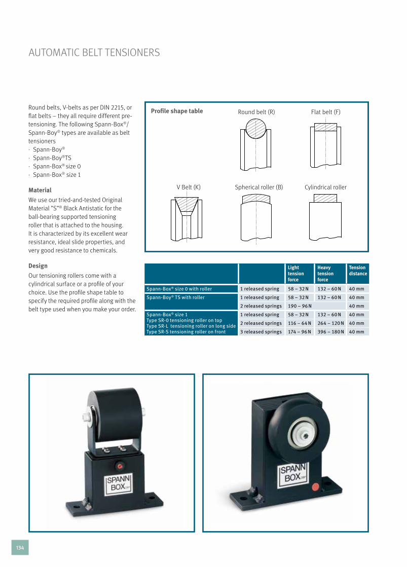
AuTOMATIc BELT TEnSIOnErS
automatische riemenspanner
profile shape tableround belts, V-belts as per DIn 2215, or flat belts – they all require different pre-tensioning. The following Spann-Box®/Spann-Boy® types are available as belt tensioners· Spann-Boy®
· Spann-Boy®TS· Spann-Box® size 0· Spann-Box® size 1
Material
We use our tried-and-tested Original Material ”S”® Black Antistatic for the ball-bearing supported tensioning roller that is attached to the housing. It is characterized by its excellent wear resistance, ideal slide properties, and very good resistance to chemicals.
design
Our tensioning rollers come with a cylindrical surface or a profile of your choice. use the profile shape table to specify the required profile along with the belt type used when you make your order.
round belt (r) Flat belt (F)
Spherical roller (B) cylindrical rollerV Belt (k)
light tension force
heavy tension force
tension distance
Spann-Box® size 0 with roller 1 released spring 58 – 32 N 132 – 60 N 40 mm
Spann-Boy® TS with roller 1 released spring 58 – 32 N 132 – 60 N 40 mm
2 released springs 190 – 96 N 40 mm
Spann-Box® size 1 Type SR-0 tensioning roller on topType SR-L tensioning roller on long sideType SR-S tensioning roller on front
1 released spring 58 – 32 N 132 – 60 N 40 mm
2 released springs 116 – 64 N 264 – 120 N 40 mm
3 released springs 174 – 96 N 396 – 180 N 40 mm
134

TE
NS
ION
ING
Sy
ST
EM
SA
UTO
MA
TIC
BE
lT T
EN
SIO
NE
RS
SPANN-BOY® TS AS BELT TENSIONER
roller widthmm
profile shape article no.
20
Cylindrical 281 160 001
Spherical 281 160 004
Flat belt 281 160 007
V-belt 281 160 010
Round belt 281 160 013
30
Cylindrical 281 160 002
Spherical 281 160 005
Flat belt 281 160 008
V-belt 281 160 011
Round belt 281 160 014
40
Cylindrical 281 160 003
Spherical 281 160 006
Flat belt 281 160 009
V-belt 281 160 012
Round belt 281 160 015
Special and stainless steel designs on request
Tension pressure· Spann-Boy® TS has one light and one
heavy pressure spring that can be released together or separately depen-ding on the required tension pressure.
attachment
· Bore holes in the housing (for matching fastening brackets refer to pages 118 - 119)
three tension pressure settings
with roller 44 mm40 mm
135

SPANN-BOX® SIzE 0 AS BELT TENSIONERwith roller
roller widthmm
profile shape light tension force article no.
heavy tension forcearticle no.
20 Cylindrical 281 100 001 281 100 002
Spherical 281 100 007 281 100 008
Flat belt 281 100 013 281 100 014
V-belt 281 100 019 281 100 020
Round belt 281 100 025 281 100 026
30 Cylindrical 281 100 003 281 100 004
Spherical 281 100 009 281 100 010
Flat belt 281 100 015 281 100 016
V-belt 281 100 021 281 100 022
Round belt 281 100 027 281 100 028
40 Cylindrical 281 100 005 281 100 006
Spherical 281 100 011 281 100 012
Flat belt 281 100 017 281 100 018
V-belt 281 100 023 281 100 024
Round belt 281 100 029 281 100 030
Special and stainless steel designs on request
design
· corrosion-proof housing
tensioning pressure
· choice of light or heavy spring force
25 mm40 mm
136

TE
NS
ION
ING
Sy
ST
EM
SA
UTO
MA
TIC
BE
lT T
EN
SIO
NE
RS
SPANN-BOX® SIzE 1 AS BELT TENSIONER
roller widthmm
profile shape light tension forcearticle no.
heavy tension forcearticle no.
53 Cylindrical 281 110 001 281 110 002
Shperical 281 110 003 281 110 004
Flat belt 281 110 005 281 110 006
V-belt 281 110 007 281 110 008
Round belt 281 110 009 281 110 010
Special and stainless steel designs on request
Our tried-and-tested Spann-Box® is ideally suited for use as a belt tensioner. We offer different designs for different scenarios. The variants differ primarily in the mounting of the tensioning roller. The basic design is identical for all variants.
tensioning pressure
· choice of light or heavy spring force
attachment
· Bore holes in the housing (for matching fastening brackets refer to pages 118 - 119)
SPAnn-BOX® SIZE 1as belt tensioner with roller
40 mm 67 mm
137

SPAnn-BOX® SIZE 1 / TyPE Sr-Ltensioning roller on long side
roller widthmm
profile shape light tension forcearticle no.
heavy tension forcearticle no.
20 Cylindrical 281 110 011 281 110 012
Spherical 281 110 017 281 110 018
Flat belt 281 110 023 281 110 024
V-belt 281 110 029 281 110 030
Round belt 281 110 035 281 110 036
30 Cylindrical 281 110 013 281 110 014
Spherical 281 110 019 281 110 020
Flat belt 281 110 025 281 110 026
V-belt 281 110 031 281 110 032
Round belt 281 110 037 281 110 038
40 Cylindrical 281 110 015 281 110 016
Spherical 281 110 021 281 110 022
Flat belt 281 110 027 281 110 028
V-belt 281 110 033 281 110 034
Round belt 281 110 039 281 110 040
Special and stainless steel designs on request
40 mm 67 mm
138

TE
NS
ION
ING
Sy
ST
EM
SA
UTO
MA
TIC
BE
lT T
EN
SIO
NE
RS
roller widthmm
profile shape light tension forcearticle no.
heavy tension forcearticle no.
20 Cylindrical 281 110 041 281 110 042
Spherical 281 110 047 281 110 048
Flat belt 281 110 053 281 110 054
V-belt 281 110 059 281 110 060
Round belt 281 110 065 281 110 066
30 Cylindrical 281 110 043 281 110 044
Spherical 281 110 049 281 110 050
Flat belt 281 110 055 281 110 056
V-belt 281 110 061 281 110 062
Round belt 281 110 067 281 110 068
40 Cylindrical 281 110 045 281 110 046
Spherical 281 110 051 281 110 052
Flat belt 281 110 057 281 110 058
V-belt 281 110 063 281 110 064
Round belt 281 110 069 281 110 070
SPAnn-BOX® SIZE 1 / TyPE Sr-Stensioning roller on front
Special and stainless steel designs on request
40 mm 67 mm
139
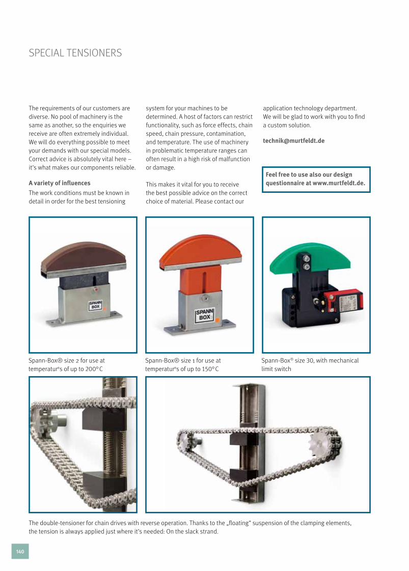
SPEcIAL TEnSIOnErS
Spann-Box® size 2 for use at temperatures of up to 200° c
Spann-Box® size 1 for use at temperatures of up to 150° c
Spann-Box® size 30, with mechanical limit switch
The double-tensioner for chain drives with reverse operation. Thanks to the „floating“ suspension of the clamping elements, the tension is always applied just where it‘s needed: On the slack strand.
The requirements of our customers are diverse. no pool of machinery is the same as another, so the enquiries we receive are often extremely individual. We will do everything possible to meet your demands with our special models. correct advice is absolutely vital here – it‘s what makes our components reliable.
a variety of influences
The work conditions must be known in detail in order for the best tensioning
system for your machines to be determined. A host of factors can restrict functionality, such as force effects, chain speed, chain pressure, contamination, and temperature. The use of machinery in problematic temperature ranges can often result in a high risk of malfunction or damage.
This makes it vital for you to receive the best possible advice on the correct choice of material. Please contact our
application technology department. We will be glad to work with you to find a custom solution. [email protected]
feel free to use also our design questionnaire at www.murtfeldt.de.
140

TE
NS
ION
ING
Sy
ST
EM
SS
PE
CIA
l T
EN
SIO
NE
RS
Spann-Box® size 1 with return profile made of Murinit® SP in accordance with customer’s requirements
Spann-Box® size 1 with arc segment made from Original Material ”S”® plus+OIl for an accumulator chain
T-tension station for compensation of extensive chain lengthening
Spann-Box® size 1 or size 2, tandem tensioner for tensioning chains with extremely large chain pitches
Spann-Box® designs with locking devices; they prevent the slide profile from being compressed when the direction of rotation changes, for example.
Size 1 tension station with roller
141

142

technIcal InformatIon143

plastics thickness Width length thickness tolerance
availability
Original Material ”S”® green 2/3/4/5/6 1000 2000 +0/+0.8 ”
8 – 200 1000 2000 +0/+0.6 ”
2/3/4/5/6 1220 3000 +0/+0.8 ”
8 – 60 1000 3000 +0/+0.6 ”
65 – 120 1000 3000 +0/+0.6 @
8 – 120 1000 4000 +0/+0.6 @
8 – 60 1335 2000 +0/+0.6 ”
65 – 120 1335 2000 +0/+0.6 @
Original Material ”S”® natural 1/2/3/4/5/6 1000 2000 +0/+0.8 ”
8 – 100 1000 2000 +0/+0.6 ”
110 – 200 1000 2000 +0/+0.6 @
2/3/4/5 1220 3000 +0/+0.8 @
10 – 50 1000 3000 +0/+0.6 ”
60 – 120 1000 3000 +0/+0.6 @
8 – 120 1000 4000 +0/+0.6 @
Original Material ”S”® black antistatic 1/2/3/4/5/6 1000 2000 +0/+0.8 ”
8 – 200 1000 2000 +0/+0.6 ”
2/3/4/5/6 1220 3000 +0/+0.8 ”
8 – 50 1000 3000 +0/+0.6 ”
60 – 120 1000 3000 +0/+0.6 @
8 – 120 1000 4000 +0/+0.6 @
8 – 60 1335 2000 +0/+0.6 ”
65 – 120 1335 2000 +0/+0.6 @
Material ”S”® 8000 8 – 80 1000 2000 +0/+0.6 ”
90 – 130 1000 2000 +0/+0.6 @
Material ”S”® 1000 green 3/4/5/6 1000 2000 +0/+0.8 ”
8 – 110 1000 2000 +0/+0.6 ”
120 – 200 1000 2000 +0/+0.6 @
3/4/5/6 1220 3000 +0/+0.8 ”
8 – 60 1000 3000 +0/+0.6 ”
70 – 100 1000 3000 +0/+0.6 @
10 – 60 1335 2000 +0/+0.6 ”
70 – 120 1335 2000 +0/+0.6 @
10 – 120 1000 4000 +0/+0.6 @
Material ”S”® 1000 black antistatic 4/5 1000 2000 +0/+0.8 ”
3/6 1000 2000 +0/+0.8 @
8 – 140 1000 2000 +0/+0.6 ”
150 – 200 1000 2000 +0/+0.6 @
3/4/5/6 1220 3000 +0/+0.8 @
8 – 60 1000 3000 +0/+0.6 ”
70 – 100 1000 3000 +0/+0.6 @
10 – 60 1335 2000 +0/+0.6 ”
70 – 100 1335 2000 +0/+0.6 @
10 – 120 1000 4000 +0/+0.6 @
Material ”S”® 1000 RB 8 – 100 1000 2000 +0/+0.6 @
Original Material ”S”® plus + FP [FS] 10 – 60 1335 2000 +0/+0.6 @
Original Material ”S”® plus + LF 8 – 50 1000 2000 +0/+0.6 ”
60 – 120 1000 2000 +0/+0.6 @
Original Material ”S”® plus + LF ESD 8 – 50 1000 2000 +0/+0.6 ”
60 – 100 1000 2000 +0/+0.6 @
Original Material ”S”® plus + AB 8 – 60 1000 2000 +0/+0.6 ”
70 – 110 1000 2000 +0/+0.6 @
ShEET DIMEnSIOnS
144

plastics thickness Width length thickness tolerance
availability
Original Material ”S”® plus + TLS 8 – 50 1000 2000 +0/+0.6 ”
60 – 100 1000 2000 +0/+0.6 @
Original Material ”S”® plus + GB 8 – 50 1000 2000 +0/+0.6 ”
60 – 110 1000 2000 +0/+0.6 @
Original Material ”S”® plus + ESD 8 – 80 1000 2000 +0/+0.6 ”
90 – 110 1000 2000 +0/+0.6 @
Original Material ”S”® plus + Bright ESD 8 – 50 1000 2000 +0/+0.6 ”
60 – 110 1000 2000 +0/+0.6 @
Muralen® natural 2 – 6 1000 2000 as per DIN EN 14632 ”
8 – 100 1000 2000 +0/+0.6 ”
Muralen® plus + AB 8 – 110 1000 2000 +0/+0.6 @
Muralen® black antistatic 8 - 100 1000 2000 +0/+0.6 @
Murlubric® 8 – 100 1000 2000 +0/+0.6 ”
110 – 160 1000 1000 +0/+0.6 @
Murlubric® [FS] 10 – 100 1000 2000 as per DIN EN 15860 @
Murylon® B natural 2 – 60 1000 2000 as per DIN EN 15860 ”
70 – 100 610 2000 as per DIN EN 15860 ”
Murylon® B black 8 – 50 610 2000 as per DIN EN 15860 ”
Murylon® A natural 8 – 60 610 2000 as per DIN EN 15860 @
Murylon® A GF black 10 – 100 625 2000 as per DIN EN 15860 @
Murylon® A Cast natural 10 – 100 1000 2000 as per DIN EN 15860 ”
Murylon® A Cast black 10 – 80 1000 2000 as per DIN EN 15860 ”
Murdopol® 10 – 50 1000 2000 on request @
Murytal® C natural 1 – 100 1000 2000 as per DIN EN 15860 ”
Murytal® C black 2 – 100 1000 2000 as per DIN EN 15860 ”
Murytal® C blue [FS] 10 – 100 1000 2000 as per DIN EN 15860 @
Murytal® H natural 10 – 50 610 2000 as per DIN EN 15860 @
Murytal® ESD 12 – 40 500 2000 as per DIN EN 15860 @
Murylat® natural 8 – 100 610 2000 as per DIN EN 15860 ”
Murylat® black 8 – 80 610 2000 as per DIN EN 15860 @
Murylat® SP 8 – 100 610 2000 as per DIN EN 15860 ”
Murylon® HT 10 – 40 610 2000 as per DIN EN 15860 ”
50 500 2000 as per DIN EN 15860 ”
Murinyl® 10 – 80 610 2000 as per DIN EN 15860 @
Murflor® 3 – 50 1000 1000 as per GKV @
10 – 50 1000 2000 as per GKV ”
Murflor® Carbon 10 – 40 1000 2000 as per GKV ”
Murflor® Bronze 10 – 30 1000 2000 as per GKV ”
Murflor® Glas 10 – 30 1000 2000 as per GKV ”
Murinit® SP 8/10 525 2000 as per DIN EN 15860 ”
12 – 50 625 2000 as per DIN EN 15860 ”
Murpec® 5 – 25 1000 2000 as per DIN EN 15860 @
30 – 60 615 2000 as per DIN EN 15860 @
Murpec® SP 10 525 2000 as per DIN EN 15860 @
16/20/30/40 625 2000 as per DIN EN 15860 @
ShEET DIMEnSIOnS
Sheet sizes in mmTolerances: Widths and lenghts ≥ + 0 mm or as per DIN 16986
Other colours and dimensions (thickness x width x length) and other pre-cut parts on request
SH
EE
T D
IME
NS
ION
S
stockedon request
”
@
145 TE
CH
NIC
Al
INFO
RM
AT
ION

plastics diameter Graduations length Ø-tolerance availability
Original Material ”S”® green 10 – 100 5 1000 +0/+1 ”
Halbzeug nach dIn 16972 Tg 2 100 – 200 10 1000 +0/+1 ”
Original Material ”S”® natural 10 – 30 5 1000 +0/+1 ”
Halbzeug nach dIn 16972 Tg 2 30 – 200 10 1000 +0/+1 ”
Original Material ”S”® black antistatic 10 – 100 5 1000 +0/+1 ”
Halbzeug nach dIn 16972 Tg 2 100 – 200 10 1000 +0/+1 ”
Material ”S”® 8000 on request # 1000 +0/+1 @
Material ”S”® 1000 green on request # 1000 +0/+1 @
Material ”S”® 1000 black antistatic on request # 1000 +0/+1 @
Original Material ”S”®plus + plastics on request 10 1000 +0/+1 @
Muralen® natural 30 – 100 10 2000 on request @
Muralen® plus + AB on request 10 1000 +0/+1 @
Murlubric® 20 – 100 5 1000 as per DIN EN 15860 ”
100 – 200 10 1000 as per DIN EN 15860 ”
Murlubric® FS 20 – 100 5 1000 as per DIN EN 15860 @
100 – 200 10 1000 as per DIN EN 15860 @
Murylon® B natural 5 – 100 # 1000 as per DIN EN 15860 ”
Murylon® B black 10 – 100 # 1000 as per DIN EN 15860 @
Murylon® A natural 5 – 200 # 1000 as per DIN EN 15860 @
Murylon® A GF 10 – 200 # 1000 as per DIN EN 15860 @
Murylon® 6 Cast natural 50 –500 # 1000 as per DIN EN 15860 @
Murylon® 6 Cast black 50 –500 # 1000 as per DIN EN 15860 @
Murdopol® (rods with and without steel core) 50 – 200 10 500 on request @
Murytal® C natural 3 – 200 # 1000 as per DIN EN 15860 ”
Murytal® C black 5 – 200 # 1000 as per DIN EN 15860 ”
Murytal® C blue [FS] 15 – 200 # 1000 as per DIN EN 15860 @
Murytal® H natural 5 – 200 # 1000 as per DIN EN 15860 @
Murytal® ESD 30 – 60 # 1000 as per DIN EN 15860 @
rOD DIMEnSIOnS
Rod sizes in mmTolerances: Widths and lengths ≥ + 0 mm or as per DIN 16986
Other colours and dimensions (diameter and length) and other pre-cut parts and round discs on request. # Irregular graduations; please state required ø. We will provide you with the suitable/next largest ø.
stockedon request
”
@
146

plastics diameter Graduations length Ø-tolerance availability
Murylat® natural 10 – 210 # 1000 as per DIN EN 15860 ”
Murylat® black 20 – 150 # 1000 as per DIN EN 15860 @
Murylat® SP 10 – 150 # 1000 as per DIN EN 15860 ”
Murylon® HT 16 – 60 # 1000 as per DIN EN 15860 ”
Murinyl® 10 – 250 # 1000 as per DIN EN 15860 @
Murflor® 10 – 120 # 1000 as per GKV ”
Murflor®-Carbon 10 – 100 10 on request as per GKV @
Murflor®-Bronze 10 – 100 10 on request as per GKV @
Murflor®-Glas 10 – 100 10 on request as per GKV @
Murinit SP ® 10 – 100 # 1000 as per DIN EN 15860 ”
Murpec® 10 – 140 # 1000 as per DIN EN 15860 ”
150 – 200 # 1000 as per DIN EN 15860 @
Murpec® SP 8 – 100 # 1000 as per DIN EN 15860 @
RO
D D
IME
NS
ION
S
rOD DIMEnSIOnS
Rod sizes in mmTolerances: Widths and lengths ≥ + 0 mm or as per DIN 16986
Other colours and dimensions (diameter and length) and other pre-cut parts and round discs on request. # Irregular graduations; please state required ø. We will provide you with the suitable/next largest ø.
stockedon request
”
@
147 TE
CH
NIC
Al
INFO
RM
AT
ION

LEGEnD
The material characteristic tables, which are based on data from our suppliers of raw materials, are intended to help you to quickly compare/select a material. The values stated are short-term values that can be affected by processing, environmental, and application conditions. The customer is solely responsible for the suitability of the selected material for the specific application.
+ dry
++ air-moist (saturation in standard atmosphere of 23°c / 50% rH)
rF relative humidity
nB no break
HB Horizontal Burning
ul underwriters laboratories
also available as Food Safe Material ref. eu 1935/2004.
1) The mechanical and electrical characteristics are based on a test temperature of 23°c
2) Temperature stress for several hours; no or low mechanical stress (short-term service temperature)
3) Temperature stress for 5000h; then reduction (approx 50 %) of tensile strength of initial value (constant: for 5000h)
4) as the temperature decreases, the impact strength drops. The specified values are based on the most unfavourable impact load possible and do not represent absolute practical limits (lower service temperature)
5) The electric strength can be up to 50% lower than for natural coloured materials (for black Murylon® B, Murylon® a, Murytal® c/H, and Murylat®)
Chemical resistance of our materials:For a detailed selection chart, see our Internet pages at www.murtfeldt.com.
according the following material characteristic tables
148

TEchnIcAL MATErIALS
characteristics
Standard Unit OriginalMaterial ”S”®
green
OriginalMaterial ”S”®
natural
OriginalMaterial ”S”®
black antistatic
Material ”S”®1000 green
Material ”S”®
1000 blackantistatic
Material ”s”®
8000Material ”S”®
1000 RBMuralen® Muralen®
black antistatic
Muralen®plus+AB
Catalogue page 30 30 31 33 33 32 33 42 42 42
Code ISO 1043-1 PE-UHMW PE-UHMW PE-UHMW PE-UHMW PE-UHMW PE-UHMW PE-UHMW PE-HMW PE-HMW PE-HMW
Sheet group ISO 15527 – 1.2 1.2 1.2 – – 1.1 – 2.1 2.1 2.1
Material colour – – green natural black green black anthracite black natural black sky blue
Average molecular weight – g/mol 5 × 10⁶ 5 × 10⁶ 5 × 10⁶ – – 9 × 10⁶ – 0,5 × 10⁶ 0,5 × 10⁶ 0,5 × 10⁶
Density ISO 1183 kg/dm3 ≤ 0,93 ≤ 0,93 ≤ 0,93 ≤ 0,94 ≤ 0,94 ≤ 0,93 ≤ 0,95 ≤ 0,95 ≤ 0,95 ≤ 0,95
Mechanical properties 1)
Yield/break stress ISO 527 MPa 20,4 20,4 20,6 23,5 24,6 21,1 - 28 25 27,2
Breaking elongation ISO 527 % 380 380 320 360 230 265 - 660 580 630
Notch impact toughness (Charpy) ISO 179 kJ/m2 ≥ 170 ≥ 170 ≥ 120 ≥ 80 ≥ 140 ≥ 170 ≥ 80 ≥ 25 ≥ 25 ≥ 25
Shore hardness D DIN 53505 ° 66 66 61-63 61-65 64 65 61-63 66 66 66
Indentation hardness – MPa 38 38 38 38 38 43 38 45 45 45
Sand-Slurry-Test – % 100 100 110 120 120 90 150 350 350 350
Coefficient of sliding friction (dry) – – 0,1-0,2 0,1-0,2 0,1-0,2 0,1-0,2 0,1-0,2 0,1-0,2 >0,2 0,1-0,2 0,1-0,2 0,1-0,2
Thermal properties
Heat conductivity at 23° C ISO 52612 W/(K × m) 0,4 0,4 0,4 0,4 0,4 0,4 0,4 0,4 0,4 0,4
Linear thermal coefficient of expansion α: ISO 11359
– Average value between 23 and 60° C m/(m × K) 20 × 10-5 20 × 10-5 20 × 10-5 20 × 10-5 20 × 10-5 17 × 10-5 20 × 10-5 20 × 10-5 20 × 10-5 20 × 10-5
Upper service temperature in air:
– Short-term service temperature 2) – °C 90 90 90 90 90 90 90 90 90 90
– Constant: for 5000 h 3) – °C 80 80 80 80 80 80 80 80 80 80
Lower service temperature 4) – °C -200 -200 -150 -150 -150 -200 -100 -100 -100 -100
Burning behaviour as per UL94 – – HB HB HB HB HB HB HB HB HB HB
Electrical properties
Electric strength IEC 60243 kV/mm ≤ 45 ≤ 45 – ≤ 45 – ≤ 45 – ≤ 45 – ≤ 45
Specific contact resistance IEC 60093 E × cm > 1014 > 1014 ≤ 106 > 1014 ≤ 106 > 1016 – > 1014 > 106 > 1014
Surface resistance IEC 60093 E > 1013 > 1013 ≤ 109 > 1013 ≤109 > 1013 – > 1013 > 109 > 1013
Physiological properties
Approved for use in the food industry – FDA – – Yes Yes Yes No No – No Yes Yes Yes
Approved for use in the food industry – EU 1935/2004 (only [FS] material) – – Yes Yes Yes – – – – Yes – Yes
149

Standard Unit OriginalMaterial ”S”®
green
OriginalMaterial ”S”®
natural
OriginalMaterial ”S”®
black antistatic
Material ”S”®1000 green
Material ”S”®
1000 blackantistatic
Material ”s”®
8000Material ”S”®
1000 RBMuralen® Muralen®
black antistatic
Muralen®plus+AB
Catalogue page 30 30 31 33 33 32 33 42 42 42
Code ISO 1043-1 PE-UHMW PE-UHMW PE-UHMW PE-UHMW PE-UHMW PE-UHMW PE-UHMW PE-HMW PE-HMW PE-HMW
Sheet group ISO 15527 – 1.2 1.2 1.2 – – 1.1 – 2.1 2.1 2.1
Material colour – – green natural black green black anthracite black natural black sky blue
Average molecular weight – g/mol 5 × 10⁶ 5 × 10⁶ 5 × 10⁶ – – 9 × 10⁶ – 0,5 × 10⁶ 0,5 × 10⁶ 0,5 × 10⁶
Density ISO 1183 kg/dm3 ≤ 0,93 ≤ 0,93 ≤ 0,93 ≤ 0,94 ≤ 0,94 ≤ 0,93 ≤ 0,95 ≤ 0,95 ≤ 0,95 ≤ 0,95
Mechanical properties 1)
Yield/break stress ISO 527 MPa 20,4 20,4 20,6 23,5 24,6 21,1 - 28 25 27,2
Breaking elongation ISO 527 % 380 380 320 360 230 265 - 660 580 630
Notch impact toughness (Charpy) ISO 179 kJ/m2 ≥ 170 ≥ 170 ≥ 120 ≥ 80 ≥ 140 ≥ 170 ≥ 80 ≥ 25 ≥ 25 ≥ 25
Shore hardness D DIN 53505 ° 66 66 61-63 61-65 64 65 61-63 66 66 66
Indentation hardness – MPa 38 38 38 38 38 43 38 45 45 45
Sand-Slurry-Test – % 100 100 110 120 120 90 150 350 350 350
Coefficient of sliding friction (dry) – – 0,1-0,2 0,1-0,2 0,1-0,2 0,1-0,2 0,1-0,2 0,1-0,2 >0,2 0,1-0,2 0,1-0,2 0,1-0,2
Thermal properties
Heat conductivity at 23° C ISO 52612 W/(K × m) 0,4 0,4 0,4 0,4 0,4 0,4 0,4 0,4 0,4 0,4
Linear thermal coefficient of expansion α: ISO 11359
– Average value between 23 and 60° C m/(m × K) 20 × 10-5 20 × 10-5 20 × 10-5 20 × 10-5 20 × 10-5 17 × 10-5 20 × 10-5 20 × 10-5 20 × 10-5 20 × 10-5
Upper service temperature in air:
– Short-term service temperature 2) – °C 90 90 90 90 90 90 90 90 90 90
– Constant: for 5000 h 3) – °C 80 80 80 80 80 80 80 80 80 80
Lower service temperature 4) – °C -200 -200 -150 -150 -150 -200 -100 -100 -100 -100
Burning behaviour as per UL94 – – HB HB HB HB HB HB HB HB HB HB
Electrical properties
Electric strength IEC 60243 kV/mm ≤ 45 ≤ 45 – ≤ 45 – ≤ 45 – ≤ 45 – ≤ 45
Specific contact resistance IEC 60093 E × cm > 1014 > 1014 ≤ 106 > 1014 ≤ 106 > 1016 – > 1014 > 106 > 1014
Surface resistance IEC 60093 E > 1013 > 1013 ≤ 109 > 1013 ≤109 > 1013 – > 1013 > 109 > 1013
Physiological properties
Approved for use in the food industry – FDA – – Yes Yes Yes No No – No Yes Yes Yes
Approved for use in the food industry – EU 1935/2004 (only [FS] material) – – Yes Yes Yes – – – – Yes – Yes
150

THe OrIgInal MaTerIal ”S”® PluS+ FaMIly
OriginalMaterial ”S”®
plus + FP [FS]
OriginalMaterial ”S”®
plus + LF
OriginalMaterial ”S”®
plus + LF ESD
OriginalMaterial ”S”®
plus + AB
OriginalMaterial ”S”®
plus + TLS
OriginalMaterial ”S”®
plus + GB
OriginalMaterial ”S”®
plus + ESD
OriginalMaterial ”S”®
plus + Bright ESD
34 35 36 37 38 39 40 41
PE-UHMW PE-UHMW PE-UHMW PE-UHMW PE-UHMW PE-UHMW PE-UHMW PE-UHMW
1.1 1.1 1.1 1.2 1.1 1.1 1.2 1.2
light blue cobalt blue black sky blue ruby red light green black light grey
9 × 10⁶ 9 × 10⁶ 9 × 10⁶ 5 × 10⁶ 9 × 10⁶ 9 × 10⁶ 5 × 10⁶ 5 × 10⁶
≤ 1,14 ≤ 0,93 ≤ 0,93 ≤ 0,93 ≤ 0,93 ≤ 0,94 ≤ 0,93 ≤ 0,93
26 20 20 20,3 23 25 20,4 21,6
250 275 255 320 250 290 290 225
≥ 100 ≥ 120 ≥ 150 ≥ 170 ≥ 140 ≥ 100 ≥ 120 ≥ 170
64 60 60 64 64 65 63 64
40 38 30 38 38 44 38 38
100 80 80 100 80 80 110 120
0,1-0,2 < 0,1 < 0,1 0,1-0,2 0,1-0,2 0,15-0,2 0,1-0,2 0,1-0,2
0,4 0,4 0,4 0,4 0,4 0,4 0,4 0,4
20 × 10-5 20 × 10-5 20 × 10-5 20 × 10-5 20 × 10-5 17 × 10-5 20 × 10-5 20 × 10-5
120 90 90 90 120 90 90 90
100 80 80 80 100 80 80 80
-200 -200 -200 -200 -200 -200 -150 -150
HB HB HB HB HB HB HB HB
≥ 45 ≤ 45 – ≤ 45 ≤ 45 ≤ 45 – –
≤ 1012 > 1014 ≤ 103 > 1014 > 1014 > 1015 ≤ 104 ≤ 105
≤ 1012 > 1013 ≤ 109 > 1013 > 1014 > 1013 ≤ 104 ≤ 105
Yes Yes Yes Yes Yes Yes Yes No
Yes Yes Yes Yes Yes – – –
CH
AR
AC
TE
RIS
TIC
S T
EC
HN
ICA
l M
AT
ER
IAlS
/ T
HE
OR
IGIN
Al
MA
TE
RIA
l ”S
”® P
lUS
+ F
AM
Ily
151 TE
CH
NIC
Al
INFO
RM
AT
ION

TEchnIcAL MATErIALS
characteristics
Standard Unit Murlubric® Murlubric® blue [FS] Murylon® B Murylon® A Murylon® A GF Murylon® 6 Cast Murdopol® Murytal® C Murytal® C blue [FS] Murytal®H Murytal® ESD
Catalogue page 43 43 44 44 45 45 46 47 47 48 48
Code ISO 1043-1 PA 6 G/Oil PA 6 G/Oil PA 6 PA 66 PA 66-GF PA 6-G PA 12-G POM-C POM-C POM-H POM-C
Material colour – – black blue natural/black natural/black black natural/black natural natural/black gentian blue natural/black natural/black
Density ISO 1183-1 g/cm³ 1,135 1,14 1,14 1,14 1,29 1,15 1,03 1,41 1,41 1,43 1,45
Water absorption – after 24 / 96 h storage in water at 23° C ISO 62 mg 44 | 83 44 | 83 86 | 168 40 | 76 30 | 56 44 | 83 – | – 20 | 37 – | – 18 | 36 18 | 36
– saturation in standard atmosphere of 23° C / 50 % RH – % 2 1,8 2,6 2,4 1,7 2,2 0,9 0,2 0,1 0,2 0,2
– saturation in water at 23° C – % 6,3 5,5 9 8 5,5 6,5 1,4 0,8 0,9 0,8 0,8
Mechanical properties 1)
Yield/break stress +/++ ISO 527-1 MPa 72 80 80/– | 45/– 90/– | 55/– -100/-100 86/– | 55/– 55/– | 55/– 66/– | 66/– 70/– | –/– 78/– | 78/– 50/– | 50/–
Breaking elongation +/++ ISO 527-1 % 25 50 > 50/> 100 50/> 100 5/12 25/> 50 200/200 50/50 > 15/– 50/50 50/50
Coefficient of elasticity (pulling test) +/++ ISO 527-1 MPa 3000 2500 3300/1425 3550/1700 5900/3200 3600/1750 2000/2000 2800/2800 3100/– 3300/3300 2300/2300
Pressure test – compression strength at 1/2/5 % nominal compression + ISO 604 MPa 22/43/79 22/43/79 24/46/80 32/62/100 28/55/90 26/51/92 – 19/35/67 19/35/67 22/40/75 –
Time-dependent creep tensile test, stress leading to an elongation of 1 % after 1000h +/++ ISO 899-1 MPa 18 18 18/7 - 26/18 22/10 – 13/13 13/13 15/15 –
Impact strength (Charpy) + ISO 179-1/1eU kJ/m² 50 NB NB NB 50 NB – 150 150 200 –
Notch impact toughness (Charpy) + ISO 179-1/1eA kJ/m² 4 >5 5,5 4,5 6 3,5 20 7 7 10 5
Indentation hardness + ISO 2039-1 N/mm² 145 140 150 160 165 165 – 140 140 160 160
Rockwell hardness + ISO 2039-2 – M 82 M 82 M 85 M 88 M 76 M 88 – M 84 M 84 M 88 M 88
Coefficient of sliding friction (dry) + – – 0,18 0,18 0,35 0,3 0,35 0,3 0,35 0,3 0,3 0,34 0,34
Sand Slurry test + – µm/km 0,05 0,05 0,23 0,1 0,28 0,12 0,8 8,9 8,9 – –
Thermal properties
Melting temperature ISO 11357-1 °C 215 215 220 260 260 215 180 165 170 180 165
Glass transition temperature ISO 11357-1 °C 50 50 50 60 60 50 - -50 -50 -50 -50
Heat conductivity at 23° C – W/(K × m) 0,28 0,23 0,28 0,28 0,3 0,29 0,23 0,31 0,31 0,31 0,31
Linear thermal coefficient of expansion: – Average value between 23 and 60° C – m/(K × m) 80 × 10-6 80 × 10-6 90 × 10-6 80 × 10-6 50 × 10-6 80 × 10-6 100 × 10-6 110 × 10-6 92 × 10-6 95 × 10-6 95 × 10-6
– Average value between 23 and 100° C – m/(K × m) 90 × 10-6 90 × 10-6 105 × 10-6 95 × 10-6 60 × 10-6 90 × 10-6 120 × 10-6 125 × 10-6 – 110 × 10-6 110 × 10-6
Upper service temperature in air: – Short-term service temperature 2) – °C 165 160 160 180 200 170 150 140 140 150 140
– Constant: for 5000 h | 20000 h 3) – °C 105 | 90 105 | 90 85 | 70 95 | 80 120 | 110 105 | 90 120 | - 115 | 100 90 | – 105/90 105 | 90
Lower service temperature 4) – °C -20 -30 -40 -30 -20 -30 -60 -50 -50 -50 -20
Burning behaviour as per UL94 – sample thickness 3/6 mm – – HB/HB HB/HB HB/HB HB/HB HB/HB HB/HB HB/- HB/HB HB/HB HB/HB HB/HB
Electrical properties 1)
Electric strength 5) +/++ IEC 60243-1 kV/mm 22 22 25/16 27/18 30/20 25/17 50/20 20/20 16,5/– 20/20 –
Specific contact resistance +/++ IEC 60093 Ohm × cm >1014 >1014 >1014/> 1012 > 1014/> 1012 > 1014/> 1013 > 1014/> 1012 > 1015/> 1012 > 1014/> 1014 > 1013/– > 1014/> 1014 ≤ 104/–
Surface resistance +/++ IEC 60093 Ohm > 1013 > 1013 > 1013/> 1012 > 1013/> 1012 > 1013/> 1012 > 1013/> 1012 > 1013/> 1012 > 1013/> 1013 > 1013/– > 1013/> 1013 ≤ 104/–
Relative permittivity: – at 100 Hz +/++ IEC 60250 – 3,5 3,5 3,9/7,4 3,8/7,4 3,9/6,9 3,6/6,6 3,5/– 3,8/3,8 –/– 3,8/3,8 –/–
– at 1 MHz +/++ IEC 60250 – 3,1 3,1 3,3/3,8 3,3/3,8 3,6/3,9 3,2/3,7 –/– 3,8/3,8 3,8/– 3,8/3,8 –/–
Dielectric loss factor: – at 100 Hz +/++ IEC 60250 – 0,015 0,015 0,019/0,13 0,013/0,13 0,012/0,19 0,012/0,14 0,038/– 0,003/0,003 0,005/– 0,003/0,003 –/–
– at 1 MHz +/++ IEC 60250 – 0,016 0,016 0,21/0,06 0,02/0,06 0,014/0,04 0,016/0,05 –/– 0,008/0,008 –/– 0,008/0,008 –/–
Physiological properties
Approved for use in the food industry – FDA – – Yes Yes Yes Yes Yes Yes Yes Yes Yes Yes Yes
Approved for use in the food industry – EU 1935/2004 (only [FS] material) – – – – Yes / – Yes / – – – – Yes / – Yes – –
152

Standard Unit Murlubric® Murlubric® blue [FS] Murylon® B Murylon® A Murylon® A GF Murylon® 6 Cast Murdopol® Murytal® C Murytal® C blue [FS] Murytal®H Murytal® ESD
Catalogue page 43 43 44 44 45 45 46 47 47 48 48
Code ISO 1043-1 PA 6 G/Oil PA 6 G/Oil PA 6 PA 66 PA 66-GF PA 6-G PA 12-G POM-C POM-C POM-H POM-C
Material colour – – black blue natural/black natural/black black natural/black natural natural/black gentian blue natural/black natural/black
Density ISO 1183-1 g/cm³ 1,135 1,14 1,14 1,14 1,29 1,15 1,03 1,41 1,41 1,43 1,45
Water absorption – after 24 / 96 h storage in water at 23° C ISO 62 mg 44 | 83 44 | 83 86 | 168 40 | 76 30 | 56 44 | 83 – | – 20 | 37 – | – 18 | 36 18 | 36
– saturation in standard atmosphere of 23° C / 50 % RH – % 2 1,8 2,6 2,4 1,7 2,2 0,9 0,2 0,1 0,2 0,2
– saturation in water at 23° C – % 6,3 5,5 9 8 5,5 6,5 1,4 0,8 0,9 0,8 0,8
Mechanical properties 1)
Yield/break stress +/++ ISO 527-1 MPa 72 80 80/– | 45/– 90/– | 55/– -100/-100 86/– | 55/– 55/– | 55/– 66/– | 66/– 70/– | –/– 78/– | 78/– 50/– | 50/–
Breaking elongation +/++ ISO 527-1 % 25 50 > 50/> 100 50/> 100 5/12 25/> 50 200/200 50/50 > 15/– 50/50 50/50
Coefficient of elasticity (pulling test) +/++ ISO 527-1 MPa 3000 2500 3300/1425 3550/1700 5900/3200 3600/1750 2000/2000 2800/2800 3100/– 3300/3300 2300/2300
Pressure test – compression strength at 1/2/5 % nominal compression + ISO 604 MPa 22/43/79 22/43/79 24/46/80 32/62/100 28/55/90 26/51/92 – 19/35/67 19/35/67 22/40/75 –
Time-dependent creep tensile test, stress leading to an elongation of 1 % after 1000h +/++ ISO 899-1 MPa 18 18 18/7 - 26/18 22/10 – 13/13 13/13 15/15 –
Impact strength (Charpy) + ISO 179-1/1eU kJ/m² 50 NB NB NB 50 NB – 150 150 200 –
Notch impact toughness (Charpy) + ISO 179-1/1eA kJ/m² 4 >5 5,5 4,5 6 3,5 20 7 7 10 5
Indentation hardness + ISO 2039-1 N/mm² 145 140 150 160 165 165 – 140 140 160 160
Rockwell hardness + ISO 2039-2 – M 82 M 82 M 85 M 88 M 76 M 88 – M 84 M 84 M 88 M 88
Coefficient of sliding friction (dry) + – – 0,18 0,18 0,35 0,3 0,35 0,3 0,35 0,3 0,3 0,34 0,34
Sand Slurry test + – µm/km 0,05 0,05 0,23 0,1 0,28 0,12 0,8 8,9 8,9 – –
Thermal properties
Melting temperature ISO 11357-1 °C 215 215 220 260 260 215 180 165 170 180 165
Glass transition temperature ISO 11357-1 °C 50 50 50 60 60 50 - -50 -50 -50 -50
Heat conductivity at 23° C – W/(K × m) 0,28 0,23 0,28 0,28 0,3 0,29 0,23 0,31 0,31 0,31 0,31
Linear thermal coefficient of expansion: – Average value between 23 and 60° C – m/(K × m) 80 × 10-6 80 × 10-6 90 × 10-6 80 × 10-6 50 × 10-6 80 × 10-6 100 × 10-6 110 × 10-6 92 × 10-6 95 × 10-6 95 × 10-6
– Average value between 23 and 100° C – m/(K × m) 90 × 10-6 90 × 10-6 105 × 10-6 95 × 10-6 60 × 10-6 90 × 10-6 120 × 10-6 125 × 10-6 – 110 × 10-6 110 × 10-6
Upper service temperature in air: – Short-term service temperature 2) – °C 165 160 160 180 200 170 150 140 140 150 140
– Constant: for 5000 h | 20000 h 3) – °C 105 | 90 105 | 90 85 | 70 95 | 80 120 | 110 105 | 90 120 | - 115 | 100 90 | – 105/90 105 | 90
Lower service temperature 4) – °C -20 -30 -40 -30 -20 -30 -60 -50 -50 -50 -20
Burning behaviour as per UL94 – sample thickness 3/6 mm – – HB/HB HB/HB HB/HB HB/HB HB/HB HB/HB HB/- HB/HB HB/HB HB/HB HB/HB
Electrical properties 1)
Electric strength 5) +/++ IEC 60243-1 kV/mm 22 22 25/16 27/18 30/20 25/17 50/20 20/20 16,5/– 20/20 –
Specific contact resistance +/++ IEC 60093 Ohm × cm >1014 >1014 >1014/> 1012 > 1014/> 1012 > 1014/> 1013 > 1014/> 1012 > 1015/> 1012 > 1014/> 1014 > 1013/– > 1014/> 1014 ≤ 104/–
Surface resistance +/++ IEC 60093 Ohm > 1013 > 1013 > 1013/> 1012 > 1013/> 1012 > 1013/> 1012 > 1013/> 1012 > 1013/> 1012 > 1013/> 1013 > 1013/– > 1013/> 1013 ≤ 104/–
Relative permittivity: – at 100 Hz +/++ IEC 60250 – 3,5 3,5 3,9/7,4 3,8/7,4 3,9/6,9 3,6/6,6 3,5/– 3,8/3,8 –/– 3,8/3,8 –/–
– at 1 MHz +/++ IEC 60250 – 3,1 3,1 3,3/3,8 3,3/3,8 3,6/3,9 3,2/3,7 –/– 3,8/3,8 3,8/– 3,8/3,8 –/–
Dielectric loss factor: – at 100 Hz +/++ IEC 60250 – 0,015 0,015 0,019/0,13 0,013/0,13 0,012/0,19 0,012/0,14 0,038/– 0,003/0,003 0,005/– 0,003/0,003 –/–
– at 1 MHz +/++ IEC 60250 – 0,016 0,016 0,21/0,06 0,02/0,06 0,014/0,04 0,016/0,05 –/– 0,008/0,008 –/– 0,008/0,008 –/–
Physiological properties
Approved for use in the food industry – FDA – – Yes Yes Yes Yes Yes Yes Yes Yes Yes Yes Yes
Approved for use in the food industry – EU 1935/2004 (only [FS] material) – – – – Yes / – Yes / – – – – Yes / – Yes – –
CH
AR
AC
TE
RIS
TIC
S T
EC
HN
ICA
l M
AT
ER
IAlS
153 TE
CH
NIC
Al
INFO
RM
AT
ION

hIGh-PErFOrMAncE MATErIALS
characteristics
Standard Unit Murylat® Murylat® SP Murylon® HT Murinyl® Murflor® Murflor®
+ Carbon (25%)Murflor®
+ Bronze (60%)Murinit® SP Murpec® Murpec® SP
Catalogue page 49 49 50 51 52 53 53 54 55 56
Code ISO 1043-1 – PETP PETP-SP PA 46 PVDF PTFE PTFE-C PTFE CuSn PPS-SP PEEK PEEK-SP
Material colour – – natural/black light grey auburn natural natural black bronze dark blue natural/black black
Density ISO 1183-1 g/cm3 1,39 1,44 1,18 1,79 2,18 2,1 3,88 1,42 1,31 1,45
Water absorption – after 24 / 96h storage in water at 23° C ISO 62 mg 6 | 13 5 | 11 90 | 180 – – – – 1 | 2 5 | 10 4 | 9
– saturation in standard atmosphere of 23° C / 50 % RH – % 0,25 0,23 2,8 0,01 – – – 0,05 0,2 0,16
– saturation in water – % 0,5 0,47 9,5 0,05 – – – 0,2 0,45 0,35
Mechanical properties 1)
Yield/break stress + | ++ ISO 527-1 | -2 MPa 90/– | 90/– 76/ – | 76/– 105/– | 55/– 50/– 20/– | –/– 15/– | –/– 14/– | –/– –/78 115 –/85
Breaking elongation + | ++ ISO 527-1 | -2 % 15 | 15 5 | 5 25 | > 100 – | – 300 | – 180 | – 140 | – 3,5 17 3
Coefficient of elasticity (pulling test) + | ++ ISO 527-1 | -2 MPa 3500 | 3500 3300 | 3300 3400 | 1350 2300 | – 750 | – – | 1270 – | 1380 4000 4300 5900
Pressure test – compression strength at 1/2/5 % nominal compression + ISO 604 MPa 26 | 51 | 103 24 | 47 | 95 23 | 45 | 94 17 | 32 | – 4,5 | – | – 10 | – | – 10,5 | – | – 33 | 65 38 | 75 44 | 86
Time-dependent creep tensile test, stress leading to an elongation of 1 % after 1000h + | ++ ISO 899-1 MPa 26 | 26 23 | 23 22 | 7,5 10 – – – – – –
Impact strength (Charpy) + ISO 179-1/1eU kJ/m² 50 30 NB – – – – 25 NB 25
Notch impact toughness (Charpy) + ISO 179-1/1eA kJ/m² 2 2,5 8 10 16 8 11 4 3,5 3
Indentation hardness + ISO 2039-1 N/mm² 170 160 165 – – – – 160 190 215
Rockwell hardness + ISO 2039-2 - M 96 M 94 M 92 – – – – M 82 M 105 M 85
Coefficient of sliding friction (dry) + – - 0,3 0,18 0,34 0,35 0,08 0,12 0,14 0,2 0,2 0,15
Sand Slurry test + – µm/km – 0,05 – 21 21 1 0,5 0,1 0,3 0,05
Thermische Eigenschaften
Melting temperature ISO 11357-1 °C 245 245 290 175 321 330 330 280 340 340
Glass transition temperature ISO 11357-1 °C 70 70 80 – 127 127 127 100 143 143
Heat conductivity at 23° C – W/(k × m) 0,29 0,29 0,30 0,19 0,23 0,64 0,64 0,3 0,25 0,78
Linear thermal coefficient of expansion:
– Average value between 23 and 60° C – m/(m × K) 60 × 10–6 65 × 10–6 80 × 10–6 125 × 10–6 – – – 50 × 10–6 50 × 10–6 35 × 10–6
– Average value between23 and 100° C – m/(m × K) 80 × 10–6 85 × 10–6 90 × 10–6 140 × 10–6 160 × 10–6 95 × 10–6 95 × 10–6 60 × 10–6 55 × 10–6 40 × 10–6
– Average value above 150° C – – – – – – – – – 100 × 10–6 130 × 10–6 85 × 10–6
Upper service temperature in air: – short term 2) – °C 160 160 200 160 300 300 300 260 310 310
– constant for 5000 | 20000 h 3) – °C 115 | 100 115 | 100 150/130 – | 150 – | 260 – | 260 – | 260 220 250 250
Lower service temperature 4) – °C -20 -20 -40 -50 -200 -200 -200 -20 -50 -20
Burning behaviour as per UL94 (sample thickness 3 | 6 mm) – – HB | HB HB | HB HB | HB V-0 | V-0 V-0 | V-0 V-0 | V-0 V-0 | V-0 V-0 | V-0 V-0 | V-0 V-0 | V-0
Electrical properties1)
Electric strength 5) +/++ IEC 60243-1 kV/mm 22/22 21/21 25/15 18/– 20/– –/– –/– 24 24 –
Specific contact resistance +/++ IEC 60093 Ohm × cm >1014/>1014 >1014/>1014 >1014/>1012 1014/– 1017/– 103–106/– –/– >1014 >1014 –
Surface resistance +/++ IEC 60093 Ohm >1013/>1013 >1013/>1013 >1013/>1012 1013/– 1015/– 103–106/– –/– >1013 >1013 –
Relative permittivity: – at 100 Hz +/++ IEC 60250 – 3,4/3,4 3,4/3,4 3,8/7,4 7,4/– 2/– –/– –/– 3,3 3,2 –
– at 1 MHz +/++ IEC 60250 – 3,2/3,2 3,2/3,2 3,4/3,8 6/– 2,1/– –/– –/– 3,3 3,2 –
Dielectric loss factor: – at 100 Hz +/++ IEC 60250 – 0,001/0,001 0,001/0,001 0,009/0,13 0,025/– <0,0003/– –/– –/– 0,003 0,001 –
– at 1 MHz +/++ IEC 60250 – 0,014/0,014 0,014/0,014 0,019/0,06 0,165/– <0,0001/– –/– –/– 0,003 0,002 –
Physiological properties
Approved for use in the food industry – FDA – – Yes Yes Yes Yes Yes No No Yes Yes No
Approved for use in the food industry – EU 1935/2004 (only [FS] material) – – Yes / – Yes – – – – – Yes Yes / – –
154

CH
AR
AC
TE
RIS
TIC
S H
IGH
-PE
RFO
RM
AN
CE
MA
TE
RIA
lS
Standard Unit Murylat® Murylat® SP Murylon® HT Murinyl® Murflor® Murflor®
+ Carbon (25%)Murflor®
+ Bronze (60%)Murinit® SP Murpec® Murpec® SP
Catalogue page 49 49 50 51 52 53 53 54 55 56
Code ISO 1043-1 – PETP PETP-SP PA 46 PVDF PTFE PTFE-C PTFE CuSn PPS-SP PEEK PEEK-SP
Material colour – – natural/black light grey auburn natural natural black bronze dark blue natural/black black
Density ISO 1183-1 g/cm3 1,39 1,44 1,18 1,79 2,18 2,1 3,88 1,42 1,31 1,45
Water absorption – after 24 / 96h storage in water at 23° C ISO 62 mg 6 | 13 5 | 11 90 | 180 – – – – 1 | 2 5 | 10 4 | 9
– saturation in standard atmosphere of 23° C / 50 % RH – % 0,25 0,23 2,8 0,01 – – – 0,05 0,2 0,16
– saturation in water – % 0,5 0,47 9,5 0,05 – – – 0,2 0,45 0,35
Mechanical properties 1)
Yield/break stress + | ++ ISO 527-1 | -2 MPa 90/– | 90/– 76/ – | 76/– 105/– | 55/– 50/– 20/– | –/– 15/– | –/– 14/– | –/– –/78 115 –/85
Breaking elongation + | ++ ISO 527-1 | -2 % 15 | 15 5 | 5 25 | > 100 – | – 300 | – 180 | – 140 | – 3,5 17 3
Coefficient of elasticity (pulling test) + | ++ ISO 527-1 | -2 MPa 3500 | 3500 3300 | 3300 3400 | 1350 2300 | – 750 | – – | 1270 – | 1380 4000 4300 5900
Pressure test – compression strength at 1/2/5 % nominal compression + ISO 604 MPa 26 | 51 | 103 24 | 47 | 95 23 | 45 | 94 17 | 32 | – 4,5 | – | – 10 | – | – 10,5 | – | – 33 | 65 38 | 75 44 | 86
Time-dependent creep tensile test, stress leading to an elongation of 1 % after 1000h + | ++ ISO 899-1 MPa 26 | 26 23 | 23 22 | 7,5 10 – – – – – –
Impact strength (Charpy) + ISO 179-1/1eU kJ/m² 50 30 NB – – – – 25 NB 25
Notch impact toughness (Charpy) + ISO 179-1/1eA kJ/m² 2 2,5 8 10 16 8 11 4 3,5 3
Indentation hardness + ISO 2039-1 N/mm² 170 160 165 – – – – 160 190 215
Rockwell hardness + ISO 2039-2 - M 96 M 94 M 92 – – – – M 82 M 105 M 85
Coefficient of sliding friction (dry) + – - 0,3 0,18 0,34 0,35 0,08 0,12 0,14 0,2 0,2 0,15
Sand Slurry test + – µm/km – 0,05 – 21 21 1 0,5 0,1 0,3 0,05
Thermische Eigenschaften
Melting temperature ISO 11357-1 °C 245 245 290 175 321 330 330 280 340 340
Glass transition temperature ISO 11357-1 °C 70 70 80 – 127 127 127 100 143 143
Heat conductivity at 23° C – W/(k × m) 0,29 0,29 0,30 0,19 0,23 0,64 0,64 0,3 0,25 0,78
Linear thermal coefficient of expansion:
– Average value between 23 and 60° C – m/(m × K) 60 × 10–6 65 × 10–6 80 × 10–6 125 × 10–6 – – – 50 × 10–6 50 × 10–6 35 × 10–6
– Average value between23 and 100° C – m/(m × K) 80 × 10–6 85 × 10–6 90 × 10–6 140 × 10–6 160 × 10–6 95 × 10–6 95 × 10–6 60 × 10–6 55 × 10–6 40 × 10–6
– Average value above 150° C – – – – – – – – – 100 × 10–6 130 × 10–6 85 × 10–6
Upper service temperature in air: – short term 2) – °C 160 160 200 160 300 300 300 260 310 310
– constant for 5000 | 20000 h 3) – °C 115 | 100 115 | 100 150/130 – | 150 – | 260 – | 260 – | 260 220 250 250
Lower service temperature 4) – °C -20 -20 -40 -50 -200 -200 -200 -20 -50 -20
Burning behaviour as per UL94 (sample thickness 3 | 6 mm) – – HB | HB HB | HB HB | HB V-0 | V-0 V-0 | V-0 V-0 | V-0 V-0 | V-0 V-0 | V-0 V-0 | V-0 V-0 | V-0
Electrical properties1)
Electric strength 5) +/++ IEC 60243-1 kV/mm 22/22 21/21 25/15 18/– 20/– –/– –/– 24 24 –
Specific contact resistance +/++ IEC 60093 Ohm × cm >1014/>1014 >1014/>1014 >1014/>1012 1014/– 1017/– 103–106/– –/– >1014 >1014 –
Surface resistance +/++ IEC 60093 Ohm >1013/>1013 >1013/>1013 >1013/>1012 1013/– 1015/– 103–106/– –/– >1013 >1013 –
Relative permittivity: – at 100 Hz +/++ IEC 60250 – 3,4/3,4 3,4/3,4 3,8/7,4 7,4/– 2/– –/– –/– 3,3 3,2 –
– at 1 MHz +/++ IEC 60250 – 3,2/3,2 3,2/3,2 3,4/3,8 6/– 2,1/– –/– –/– 3,3 3,2 –
Dielectric loss factor: – at 100 Hz +/++ IEC 60250 – 0,001/0,001 0,001/0,001 0,009/0,13 0,025/– <0,0003/– –/– –/– 0,003 0,001 –
– at 1 MHz +/++ IEC 60250 – 0,014/0,014 0,014/0,014 0,019/0,06 0,165/– <0,0001/– –/– –/– 0,003 0,002 –
Physiological properties
Approved for use in the food industry – FDA – – Yes Yes Yes Yes Yes No No Yes Yes No
Approved for use in the food industry – EU 1935/2004 (only [FS] material) – – Yes / – Yes – – – – – Yes Yes / – –
155 TE
CH
NIC
Al
INFO
RM
AT
ION

cOnSTAnT SErVIcE TEMPErATurES In °ccomparison of Materials
Original Material ”S”® green/natural
Original Material ”S”® black antistatic
Material ”S”® 8000
Material ”S”® 1000 green
Material ”S”® 1000 black antistatic
Material ”S”® 1000 RB
Original Material ”S”® plus + FP [FS]
Original Material ”S”® plus + LF
Original Material ”S”® plus + LF ESD
Original Material ”S”® plus + AB
Original Material ”S”® plus + TLS
Original Material ”S”® plus + GB
Original Material ”S”® plus + ESD
Original Material ”S”® plus + Bright ESD
Muralen®/Muralen® plus + AB
Murlubric®
Murlubric® [FS]
Murylon® B
Murylon® A
Murylon® A GF
Murylon® 6 Cast
Murdopol®
Murytal® C
Murytal® C blue [FS]
Murytal® H
Murytal® ESD
Murylat®
Murylat® SP
Murylon® HT
Murinyl®
Murflor®
Murflor® + Carbon
Murflor® + Bronze
Murinit® SP
Murpec®
Murpec® SP
50 100 150 200 250 3000
80
80
80
80
80
80
80
80
80
80
80
100
80
80
80
105
105
85
90
95
120
105
120
115
105
105
115
115
155
150*
260*
260*
260*
220*
250*
250*
(for 5.000 h) *(for 20.000 h)
°c
156

SLIDInG FrIcTIOn cOEFFIcIEnTcomparison of Materials
0,10 0,15 0,20 0,25 0,30 0,350,050,00
0,1 – 0,2
0,1 – 0,2
0,1 – 0,2
0,1 – 0,2
0,1 – 0,2
0,1 – 0,2
0,1 – 0,2
0,1 – 0,2
0,1 – 0,2
0,1 – 0,2
0,1 – 0,2
0,06 – 0,1
0,06 – 0,1
0,18
0,18
0,18
0,35
≥ 0,3
0,3
0,35
0,3
0,35
0,3
0,3
0,3
0,18
0,34
0,08
0,12
0,14
0,2
0,2
0,15
0,34
0,35
0,3
Original Material ”S”® green/natural
Original Material ”S”® black antistatic
Material ”S”® 8000
Material ”S”® 1000 green
Material ”S”® 1000 black antistatic
Material ”S”® 1000 RB
Original Material ”S”® plus + FP [FS]
Original Material ”S”® plus + LF
Original Material ”S”® plus + LF ESD
Original Material ”S”® plus + AB
Original Material ”S”® plus + TLS
Original Material ”S”® plus + GB
Original Material ”S”® plus + ESD
Original Material ”S”® plus + Bright ESD
Muralen®/Muralen® plus + AB
Murlubric®
Murlubric® [FS]
Murylon® B
Murylon® A
Murylon® A GF
Murylon® 6 Cast
Murdopol®
Murytal® C
Murytal® C blue [FS]
Murytal® H
Murytal® ESD
Murylat®
Murylat® SP
Murylon® HT
Murinyl®
Murflor®
Murflor® + Carbon
Murflor® + Bronze
Murinit® SP
Murpec®
Murpec® SP
CO
MP
AR
ISO
N O
F M
AT
ER
IAlS
157 TE
CH
NIC
Al
INFO
RM
AT
ION

2
2
2
WEAr rESISTAncEcomparison of Materials
1 2 3 4 5 60
1 = excellent, 6 =less good
2
2
3
3
3
1,5
1,5
1,5
1,5
1,5
2
4,5
2
2
3,5
3
3
3
3,5
4
4
4
4
3
1,5
3
4
5
4
4,5
2
2,5
1,5
Original Material ”S”® green/natural
Original Material ”S”® black antistatic
Material ”S”® 8000
Material ”S”® 1000 green
Material ”S”® 1000 black antistatic
Material ”S”® 1000 RB
Original Material ”S”® plus + FP [FS]
Original Material ”S”® plus + LF
Original Material ”S”® plus + LF ESD
Original Material ”S”® plus + AB
Original Material ”S”® plus + TLS
Original Material ”S”® plus + GB
Original Material ”S”® plus + ESD
Original Material ”S”® plus + Bright ESD
Muralen®/Muralen® plus + AB
Murlubric®
Murlubric® [FS]
Murylon® B
Murylon® A
Murylon® A GF
Murylon® 6 Cast
Murdopol®
Murytal® C
Murytal® C blue [FS]
Murytal® H
Murytal® ESD
Murylat®
Murylat® SP
Murylon® HT
Murinyl®
Murflor®
Murflor® + Carbon
Murflor® + Bronze
Murinit® SP
Murpec®
Murpec® SP
158

uV rESISTAncEcomparison of Materials
0 1 2 3 4 5 6
1 = excellent, 6 =less good
5
2
2
2
2
5
5
5
5
5
5
5
5
2
2
2,5
2,5
2,5
2,5
2,5
2,5
2,5
6
6
6
4
4
4
4
1
1
1
1
3,5
3,5
3,5
Original Material ”S”® green/natural
Original Material ”S”® black antistatic
Material ”S”® 8000
Material ”S”® 1000 green
Material ”S”® 1000 black antistatic
Material ”S”® 1000 RB
Original Material ”S”® plus + FP [FS]
Original Material ”S”® plus + LF
Original Material ”S”® plus + LF ESD
Original Material ”S”® plus + AB
Original Material ”S”® plus + TLS
Original Material ”S”® plus + GB
Original Material ”S”® plus + ESD
Original Material ”S”® plus + Bright ESD
Muralen®/Muralen® plus + AB
Murlubric®
Murlubric® [FS]
Murylon® B
Murylon® A
Murylon® A GF
Murylon® 6 Cast
Murdopol®
Murytal® C
Murytal® C blue [FS]
Murytal® H
Murytal® ESD
Murylat®
Murylat® SP
Murylon® HT
Murinyl®
Murflor®
Murflor® + Carbon
Murflor® + Bronze
Murinit® SP
Murpec®
Murpec® SP
CO
MP
AR
ISO
N O
F M
AT
ER
IAlS
159 TE
CH
NIC
Al
INFO
RM
AT
ION

cOEFFIcIEnT OF EXPAnSIOncomparison of Materials
5 10 15 200x 10-5 m/(m x K)
20
20
20
20
20
17
17
20
20
20
20
20
20
20
20
8
8
9
8
5
8
10 – 15
11
11
9,5
11
6
6,5
8
13
16*
9,5*
9,5*
6
5,5
4
(between 23 and 60˚c) *(between 23 and 100˚c)
Original Material ”S”® green/natural
Original Material ”S”® black antistatic
Material ”S”® 8000
Material ”S”® 1000 green
Material ”S”® 1000 black antistatic
Material ”S”® 1000 RB
Original Material ”S”® plus + FP [FS]
Original Material ”S”® plus + LF
Original Material ”S”® plus + LF ESD
Original Material ”S”® plus + AB
Original Material ”S”® plus + TLS
Original Material ”S”® plus + GB
Original Material ”S”® plus + ESD
Original Material ”S”® plus + Bright ESD
Muralen®/Muralen® plus + AB
Murlubric®
Murlubric® [FS]
Murylon® B
Murylon® A
Murylon® A GF
Murylon® 6 Cast
Murdopol®
Murytal® C
Murytal® C blue [FS]
Murytal® H
Murytal® ESD
Murylat®
Murylat® SP
Murylon® HT
Murinyl®
Murflor®
Murflor® + Carbon
Murflor® + Bronze
Murinit® SP
Murpec®
Murpec® SP
160

CO
MP
AR
ISO
N O
F M
AT
ER
IAlS
cOEFFIcIEnT OF ELASTIcITycomparison of Materials
0 1000 2000 3000 4000 5000 6000Mpa
700
700
700
950
950
700
750
750
700
700
700
700
700
1100
3000
2500
3250
3450
5900
3500
2200
3100
3100
3600
2300
3700
3450
3300
2300
750
4250
4400
5900
1270
1380
Original Material ”S”® green/natural
Original Material ”S”® black antistatic
Material ”S”® 8000
Material ”S”® 1000 green
Material ”S”® 1000 black antistatic
Original Material ”S”® plus + FP [FS]
Original Material ”S”® plus + LF
Original Material ”S”® plus + LF ESD
Original Material ”S”® plus + AB
Original Material ”S”® plus + TLS
Original Material ”S”® plus + GB
Original Material ”S”® plus + ESD
Original Material ”S”® plus + Bright ESD
Muralen®/Muralen® plus + AB
Murlubric®
Murlubric® [FS]
Murylon® B
Murylon® A
Murylon® A GF
Murylon® 6 Cast
Murdopol®
Murytal® C
Murytal® C blue [FS]
Murytal® H
Murytal® ESD
Murylat®
Murylat® SP
Murylon® HT
Murinyl®
Murflor®
Murflor® + Carbon
Murflor® + Bronze
Murinit® SP
Murpec®
Murpec® SP
161 TE
CH
NIC
Al
INFO
RM
AT
ION

InFOrMATIOn On ThE BEhAVIOur OF PLASTIcS
Plastics are known for their light weight and many uses – thanks to the incorporation of additives. however, plastics often respond differently to external factors than the much more familiar material – metal.
1. thermal expansion
The thermal expansion of plastics, in particular, is greater than that of metals! In the event of heat or cold, their volume on all sides of the component changes. Even when the reference temperature of 23 degrees is reached again, the plastic can retain a certain elongation or reduction, leading to dimensional differences (given by linear thermal expansion coefficients ).
2. Moisture absorption
The air humidity of the surrounding plays a key role particularly with polyamides (PA). When stored in water, for example, or when used at high levels of humidity, they can absorb up to10% water. The finished parts swell up and cause dimensional differences.
3. release of internal stresses
Plastic semi-finished products are produced at high pressure and at high temperature, causing high internal stresses when the parts cool down. These stresses are released in subsequent cutting, particularly with large changes of cross-section. cutting or machining pre-treatment and tempering in a thermal furnace can help but does not fully eliminate all stresses.
4. flow behaviour
Please note! Plastic can start to „flow“ under pressure or tensile load.
5. Machining
The elasticity of plastics is much greater than that of metal. however, there can be dimensional differences here too, depen-dent on the tool used.
rule of thumb: As a rule of thumb, a manufacturing tolerance of 0.1 % to 0.2 % of the nominal dimension (for nominal dimen-sions above 50 mm) can be maintained.
162

InFOrMATIOn On ThE BEhAVIOur OF PLASTIcS
phone 0049 231 20609-0
Should you have any questions, our application engineerswill be happy to advise you free of charge.
example
Profile made of Original Material ”S”® green 1000 mm long, produced at 20˚ c transported at summer temperatures of 40˚ cCalculation of linear expansion::2 mm per 10˚ c increase in temperature = 1004 mm
exaMple of a therMal expansIon calculatIon forMula: Vl = l ~ k ~ Vt
VL = Length changeL = Initial lengthk = Coefficient of linear expansionVT = Temperature difference in K with prefix
PlEASE NOTE:
1. InComIng goods InspeCTIon/quALITy AssurAnCe Ideally you should check Murtfeldt components at an ambient temperature of 23˚ C after a storage period of 24 hours.
2. desIgn Please take into account the thermal expansion of the plastics in the design of components. Any expected sub-sequent dimensional changes will therefore not impair the intended function of the machine part.
INFO
RM
AT
ION
ON
TH
E B
EH
AV
IOU
R O
F P
lA
ST
ICS
163 TE
CH
NIC
Al
INFO
RM
AT
ION

conversion factors for units of pressure
article no. 510012122Original Material ”S”® green, Type cT for chain 06B-1
article no. 510022122Material ”S”®1000 green, Type cT for chain 06B-1
article no. 300020153c3, galvanized steel, length of 2000 mm
article no. 301020153c3, V2a, length of 2000 mm
the c profile must be ordered separately:
uSEFuL InFOrMATIOn
Term Unit Symbol Derivation from SI units
Current Ampere A SI base unit
Charge Coulomb C 1C = 1As
Voltage Volt V 1V = 1W/A = 1m2 kg s -3 A -1
Power Watt W 1W = 1VA = 1m2 kg s -3
Resistance Ohm O 1Ohm = 1V/A = 1m2 kg s -3 A -2
Capacitance Farad F 1F = 1C/V = 1m -2 kg -1 s 4 A 2
Electrical conductance
Siemens S 1S = 1A/V = 1m -2 kg -1 s 3 A 2
Pa bar N/mm2 kp/m2 kp/cm2 (at) atm Torr
1 Pa (N/m2) = 1 10-5 10-6 0,102 0.102 *10-4 0.987 *10-5 0.0075
1 bar (daN/cm2) = 100000 1 0,1 10200 1.02 0.987 750
1 N/mm2 = 106 10 1 1.02 *105 10.2 9.87 7500
1 kp/m2 = 9.81 9.81 *10-5 9,81 *10-6 1 10-4 0.968 *10-4 0.0736
1 kp/cm2 (1 at) = 98100 0.981 0.0981 10000 1 0.968 736
1 atm (760 Torr) = 101325 1,013 0.1013 10330 1.033 1 760
1 Torr = 133 0.00133 1.33 *10-4 13.6 0.00132 0.00132 1
order example for plastic guides
1square in. (sq.in.) = 6.4516cm2 1cm2 = 0.1550sq.in.
1sq.ft. = 144 in.2 = 0.0929m2 1m2 = 10.7639sq.ft.
1sq.yd. = 9 ft.2 = 0.8361m2 1m2 = 1.19599sq.yd.
1sq.rd = 25.293m2 1m2 = 0.0395sq.rd.
1acre (A) = 4840 sq.yd. = 0.404687ha 1a = 0.0247 acre = 119.6sq.yd.
1sq.mile = 2.58999km2 1km2 = 0.387sq.mile
1barn = 1x 10-24 cm2
1 inch (in) = 2.54cm 1 cm = 0.3937in.
1 mil = 1/1000 in. = 2.54x 10⁻³cm 1 mm = 39.37mil
1 microinch = 2.54x 10⁻⁶cm 1 Mikrometre = 39.37microinch
1 foot (ft.) = 12 in. = 30.48cm 1 cm = 0.0328 ft.
1 yard = 3 ft. = 91.44cm 1 m = 1.0936yd.
1 rod (rd.) = 5.5 yd.
= 5.0292m 1 m = 0.1988rd.
1 mile (statute) = 1.60934km 1 km = 0.6214mile (st.)
1 mile (nautical) = 1.853km 1 km = 0.54mile (naut.)
length conversion table area conversion table
electricity: units
164

PIcTOGrAM LEGEnD
profiles – standard variable – optional possibilities
features and properties of tensioning system profile symbols for selection tables
US
EFU
l IN
FOR
MA
TIO
N /
PIC
TOG
RA
M l
EG
EN
D
ex stock in Material ”s”® 1000 green
In intermediate dimensions and other materials if required
6,000mm steel profile length possible
available ex stock in 1.4301 (v2a)
profile section for two-part design
original Material ”s”® green
original Material ”s”® black antistatic
Medium tolerances on plastic profile section as per DIn ISO 2768, tolerance class m
length tolerance Plastic guide +0/+7mm Steel c profile +0/+40mm
length of plastic guide and steel c profile in mm
standard design in galvanized steel
only suitable for outer facing connecting link
profile section for two-part design
for use in explosion hazard areas (manufacturer‘s declaration)
one pre-tensioned compression spring Tension distance specification in mm
two pre-tensioned compression springs Tension distance specification in mm
three pre-tensioned compression springs Tension distance specification in mm
further adjustment possible: Adjustment range in mm once original tension distance has been used
plastic housing
steel housing
track profile for all large chains
u profile for chains up to specified overall width in mm
arc segment profile
Block profile
return profile
semi-circular profile
roller/sprocket
165 TE
CH
NIC
Al
INFO
RM
AT
ION

166


SOLU
TIO
NS
IN P
LAST
ICS
SOLUTIONS IN PLASTICSCUSTOM FINISHED PRODUCTS | SEMI-FINISHED PRODUCTS | CHAIN GUIDES | CHAIN TENSIONERS
smooth. good. advised.
ww
w.m
urtf
eldt
.com
ww
w.m
urtf
eldt
.com
D/0
713/
3720
1104
7-E-
2.50
0
Heßlingsweg 14 – 16D-44309 DortmundPhone +49 231 20609-0Fax +49 231 2060992www.murtfeldt.com


