1 SONI submission of the general application of technical requirements in accordance with Articles 11 – 50 of the Commission Regulation (EU) 2016/1447 establishing a network code on high voltage direct current systems and direct current -connected power park modules 21 December 2018
Transcript
1
SONI submission of the general
application of technical requirements in
accordance with Articles 11 – 50 of the
Commission Regulation (EU) 2016/1447
establishing a network code on high
voltage direct current systems and direct
current-connected power park modules
21 December 2018
2
Disclaimer
This Proposal is submitted for general information purposes only. SONI as the
Transmission System Operator (TSO) does not;
(i) make any warranty, representation or undertaking of any kind (express or implied)
with respect to the information contained in this document (including its accuracy or
completeness); or
(ii) shall under any circumstances be liable, whether in contract, tort (including
negligence), breach of statutory duty, misrepresentation or otherwise, for any loss or
damage, direct or indirect, financial or otherwise, arising as a result of, or in connection
with, the use of this document or any reliance on the information it contains. Any and all
such liability is expressly excluded to the fullest extent permitted by law. The use of
information contained within this submission paper for any form of decision making is
This article requires an active power range (∆P/Pmax) to be defined by the TSO within
the ranges of 1.5% to 10%. The TSO did not believe that an active power range value
should be specified for continuous FSM operation as governor droop defines that
amount of active power that is provided by the DC-connected PPM or HVDC system.
The TSO consulted with the ENSTO-E Frequency Group in relation to FSM. This group
confirmed that this parameter was included as an error and as such, it was not specified
as part of this consultation.
ENSTO-E will be recommending that the requirement to specify this parameter will be
removed in the next iteration of the Network Codes.
Proposed solution:
The TSO will prepare a class derogation request to the Utility Regulator to capture this
error.
To this end, the TSO have not proposed a value for this parameter and feel that the
derogation request will cover any implementation issues in this regard.
Section 4.1.3.3, Article 39.8: FSM with subject to fast action signal
The TSO has concerns in relation to a potential loss of frequency response from PPM
units due to limitations set out in the Network Codes. The current requirements in the
Grid Code required a 60% increase in Active Power within 5 seconds and 100% of
expected increase (droop response) within 15 seconds of a frequency event. This
requirement is core to the achievement of 40% RES-E target and the ability to operate
the system at System Non Synchronous Penetration (SNSP) levels up to 75%. The
HVDC range in Article 39.8 only allow us to specify a value for the change in power
output relative to the Active Power output at the moment the frequency threshold was
13
reached (or the maximum capacity as defined by the TSO) between 1.5 – 10%, i.e. it
does not allow us to specify the levels that currently exist in the Grid Code. However, to
lose the capability provided for in today’s Grid Code would be very damaging to the
success of the DS3 program and ultimately to the integration of high levels of renewable
energy into the power system. The TSO does not believe that the regulations
intentionally undermine this capability.
Following discussions with ENTSO-E they have informed the TSO it is understood that
the requirements of the Network Codes were not intended to reduce the capability of the
fleet of generation connected to a power system. The understanding is that once a
National Code was submitted to the National Regulatory Authority by 2012 that
requirements of that code can be considered when implementing the RfG nationally.
Proposed Solution:
Therefore, the TSO is submitting a derogation request to the Utility Regulator in order to
maintain the existing Grid Code requirements for Frequency Response of PPMs,
including DC-connected PPMs.
14
6. Proposals This section covers the submission proposals for the non-exhaustive parameter
selection and non-mandatory requirement selection.
The document is laid out by theme, and in some cases further broken down into
subthemes for clarity. The five main themes are:
5.1 Frequency
5.2 Voltage
5.3 System Restoration
5.4 Instrumentation, stimulation models and protection
5.5 General Issues
Each section includes the article number and the topic being discussed. A brief
description of the requirement is provided alongside a table of the items being submitted.
The tables contain:
- a description of the parameter or requirement;
- the HVDC allowable range or an indication that a parameter needs to be
specified by the RSO;
- the submission proposal for the parameter or requirement;
- the HVDC Article reference;
- a list of the connection types that this applies to; and
- A justification code (see further below)
Justification Codes
The justification codes identify which of four assigned categories the proposed
parameters falls into. For category 1, further rationale is only provided where it is felt it is
required to aid understanding. If a proposal falls into category 2 or 3, an explanation is
provided.
1. “In line with existing”
The proposed parameter is in line with the existing Grid or Distribution Code
requirements.
2. “As close as possible to the existing”
The existing Grid or Distribution Code requirements do not fit within the
allowable HVDC range. In this case the proposed parameter is as close to
the existing Grid or Distribution Code requirements as is allowable under
HVDC.
3. “New or Different”
The requirement either does not exist in our Grid and Distribution Codes
today and a rationale for the selection is provided. In some cases we have
the requirement today but we are proposing a different value and a rationale
is provided for this choice.
4. “N/A”
Please note that in some tables we have also shown mandatory and/or exhaustive
parameters to provide context to the non-exhaustive or non-mandatory parameter.
15
These items are in greyed out cells and are not subject to submission, as the TSO does
not have the right to change them.
16
6.1 Frequency Theme
The non-exhaustive and non-mandatory frequency parameters cover a number of
different requirements. The following sub-themes are discussed in the next sections:
Frequency Ranges
Frequency Modes
Active Power Control
Synthetic Inertia
17
6.1.1 Frequency Modes Explanation
This section explains the difference between the frequency sensitive mode and limited frequency sensitive modes prior to defining the parameters.
Frequency Sensitive Mode:
The vast majority of synchronous generation units, which are currently in operation on the Transmission System today, operate in what is known in the Network Codes as Frequency Sensitive Mode (FSM). That is, generation units continuously respond to changes in the system frequency, in accordance with their governor droop characteristics for both increases and decreases in system frequency. This helps maintain the system frequency within the normal operating range.
In the HVDC parameters relating to the capability of DC-connected PPMs to operate in FSM must be specified by the TSO and are broken down into two types of parameters – responses required in normal operation and responses required following a step change in frequency:
In normal operation the parameters to be specified are the % droop and any
associated frequency dead bands. There is no parameter relating to the time
allowed to achieve the required response. These parameters are consistent with
today’s Grid Code requirements for free governor regulation.
The parameters to be specified to assist with recovering the system frequency
following a sudden imbalance and associated frequency step change are a
specified % increase in active power relative to available active power for the DC-
connected PPMs within a specified time period (usually seconds). This is similar
to today’s Grid Code Requirements for units to provide operating reserves.
These parameters also apply to PPMs. Under the existing Grid Code, PPMs are required to operate in FSM when in “% curtailed” mode. PPMs are not actually acting under the control of a traditional governor. Instead, they are moving to MW set points which are calculated in the control system based on measured changes in the system frequency. The calculation of the set point is based on the droop characteristics and time for delivery as specified in these FSM settings.
Limited Frequency Sensitive Mode:
When a unit is operating in Limited Frequency Sensitive Mode (LFSM), the unit does not provide any frequency response when the system frequency is within a specified deadband around the nominal frequency. The deadband for LFSM mode is much wider than that specified in FSM mode. FSM deadbands are very small and generally specified to reflect the technical inability of some units to respond to very small changes in frequency and/or to avoid generator hunting.
HVDC provides for different LFSM capabilities to be required for over and under frequency events. It should be noted that currently only a very small number of generation units operate in LFSM today. The only generation units which act in LFSM mode today are PPMs when in “emergency action” mode.
At the moment, it is planned to continue to operate the majority of existing and future units in FSM. However, as the transmission system evolves and new technology connects, the use of both FSM and LFSM will be assessed on a regular basis.
Summary
For clarity, the following table highlights the links between our current frequency control
modes and the HVDC frequency control modes
18
RfG Frequency Control
Mode
Equivalent Grid Code
Frequency Control Mode for
PPMs
Equivalent Grid Code
Frequency Control Mode for
SPGM
LFSM-O
Emergency Action Mode Not applicable in Northern
Ireland today
LFSM-U Not applicable in Northern
Ireland today
Not applicable in Northern
Ireland today
FSM Normal % Curtailed Mode Free Governor Action
FSM Frequency Step
Change
Same as above Operating Reserves
Table 1 – Frequency modes
For the avoidance of doubt, relay activated response such as over and under frequency
tripping of units or high frequency runback schemes are not covered by this HVDC
section as they are not related the inherent capability of the unit.
19
6.1.2 Frequency Ranges
6.1.2.1. Frequency Range for HVDC systems
Article 11.1
Mandatory non-exhaustive parameter selection
Applies to HVDC Systems
Requirement:
An HVDC system shall be capable of staying connected to the network and remaining
operable within the frequency ranges and time periods specified in Table 1, Annex I for
the short circuit power range as specified in Article 32(2).
Parameters:
Parameter Parameter in HVDC Submission
Proposal
Article
Number
Type
Applicability
Justification
Code
Frequency
range
47.0 Hz – 47.5 Hz for 60
seconds Mandatory 11.1
HVDC
Systems N/A
Frequency
Range
47.5 Hz – 48.5 Hz for a
time to specified by each
TSO, but not longer than
established times for
generation and demand.
90 minutes 11.1 HVDC
Systems 2
Frequency
Range
48.5 Hz – 49.0 Hz for a
time to be specified by
each TSO, but not
longer than established
times for generation and
demand
90 minutes 11.1 HVDC
Systems 2
Frequency
Ranges
49.0 Hz – 51.0 Hz for an
unlimited time Mandatory 11.1
HVDC
Systems N/A
Frequency
Ranges
51.0 Hz – 51.5 Hz for a
time to be specified by
each TSO, but not
longer than established
times for generation and
demand
90 minutes 11.1 HVDC
Systems 2
Frequency
Range
51.5 Hz – 52 Hz for a
time to be specified by
each TSO but longer
than for DC-connected
PPMs
60 minutes 11.1 HVDC
Systems 1
Table 2- Frequency ranges for HVDC Systems
20
Justification:
1. Frequency Range: 47.5 Hz – 48.5 Hz for 90 minutes
The proposal that a HVDC system must remain connected to the transmission
system for a period of 90 minutes when the system frequency is in the range of 47.5
Hz -48.5 Hz aligns the proposal made for the same frequency range under the RfG.
For system security reasons, it is essential that in the event of system emergency, all
available generation and HVDC systems remain connected to the transmission
system. The loss of further generation or HVDC systems during a system
emergency would be contradictory to the return of the transmission system to a
normal state. By aligning these frequency requirements, it will ensure that the
maximum time allowable to restore the transmission system to a normal state is
available.
2. Frequency Range: 48.5 Hz – 49.0 Hz for 90 minutes
The proposal that a HVDC system must remain connected to the transmission
system for a period of 90 minutes when the system frequency is in the range of 48.5
Hz – 49.0 Hz aligns the proposal made for the same frequency range under the RfG.
For system security reasons, it is essential that in the event of system emergency, all
available generation and HVDC systems remain connected to the transmission
system. The loss of further generation or HVDC systems during a system
emergency would be contradictory to the return of the transmission system to a
normal state. By aligning these frequency requirements, it will ensure that the
maximum time allowable to restore the transmission system to a normal state is
available.
3. Frequency Range: 51.0 Hz – 51.5 Hz for 90 minutes
The proposal that a HVDC system must remain connected to the transmission
system for a period of 90 minutes when the system frequency is in the range of 51.0
Hz – 51.5 Hz aligns the proposal made for the same frequency range under the RfG.
For system security reasons, it is essential that in the event of system emergency, all
available generation and HVDC systems remain connected to the transmission
system. The loss of further generation or HVDC systems during a system
emergency would be contradictory to the return of the transmission system to a
normal state. By aligning these frequency requirements, it will ensure that the
maximum time allowable to restore the transmission system to a normal state is
available.
4. Frequency Range: 51.5 Hz – 52.0 Hz for 60 minutes
The proposal that a HVDC system must remain connected to the transmission
system for a period of 60 minutes when the system frequency is in the range of 51.5
Hz – 52.0 Hz aligns the proposal made for the same frequency range under the RfG
as well as the existing Grid Code Requirements.
For system security reasons, it is essential that in the event of system emergency, all
available generation and HVDC systems remain connected to the transmission
system. The loss of further generation or HVDC systems during a system
emergency would be contradictory to the return of the transmission system to a
normal state. By aligning these frequency requirements, it will ensure that the
21
maximum time allowable to restore the transmission system to a normal state is
available.
22
6.1.2.2. Frequency Range for remote-end HVDC converter stations
Article 47.1
Mandatory non - exhaustive parameter selection
Applies to Remote-end HVDC converter stations
Requirement:
Where a nominal frequency other than 50 Hz, or a frequency variable by design is used
in the network connecting the DC-connected power park modules, subject to relevant
TSO agreement, Article 11 shall apply to the remote-end HVDC converter station with
the applicable frequency ranges and time periods specified by the relevant TSO, taking
into account specificities of the system and the requirements laid down in Annex I.
Parameters:
Parameter Parameter in
HVDC
Submission
Proposal
Article
Number
Type
Applicability
Justification
Code
Frequency
range
47.0 Hz – 47.5 Hz
for 60 seconds Mandatory 11.1
Remote end
HVDC
Converter
stations
N/A
Frequency
Range
47.5 Hz – 48.5 Hz
for a time to
specified by each
TSO, but not longer
than established
times for
generation and
demand.
90 minutes 11.1
Remote end
HVDC
Converter
stations
2
Frequency
Range
48.5 Hz – 49.0 Hz
for a time to be
specified by each
TSO, but not longer
than established
times for
generation and
demand
90 minutes 11.1
Remote end
HVDC
Converter
stations
2
Frequency
Ranges
49.0 Hz – 51.0 Hz
for an unlimited
time
Mandatory 11.1 HVDC System N/A
Frequency
Ranges
51.0 Hz – 51.5 Hz
for a time to be
specified by each
TSO, but not longer
than established
times for
generation and
demand
90 minutes 11.1
Remote end
HVDC
Converter
stations
2
23
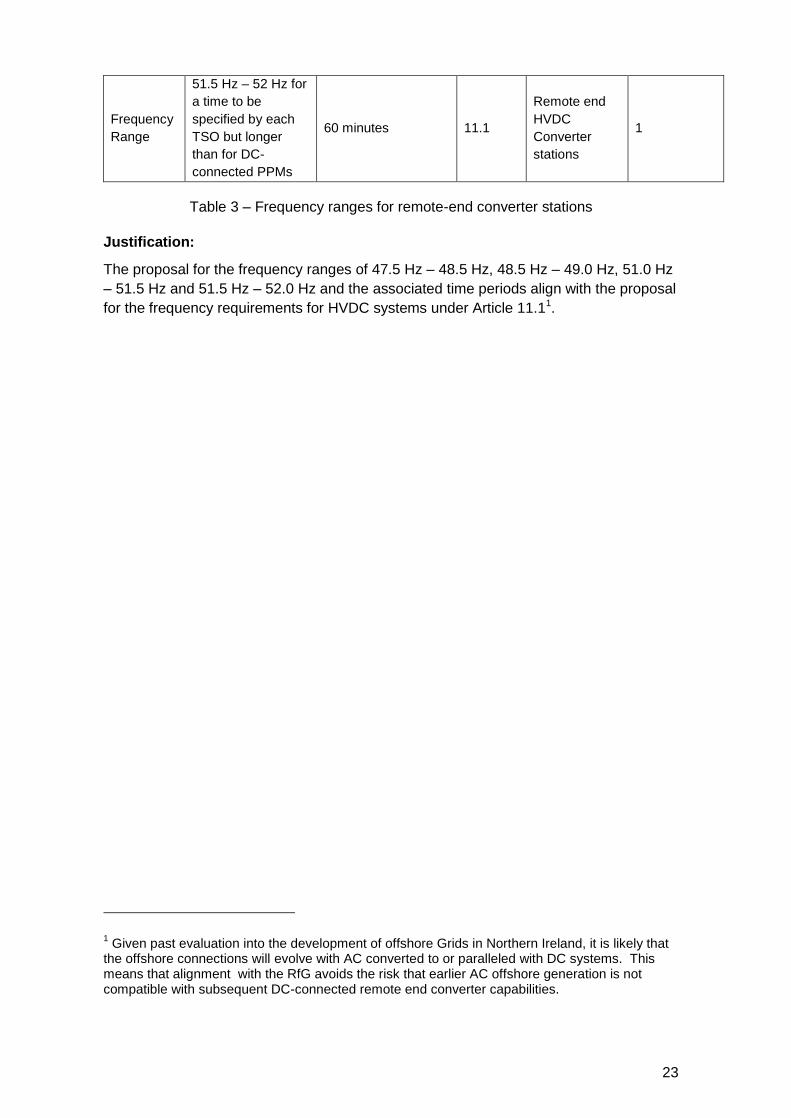
Frequency
Range
51.5 Hz – 52 Hz for
a time to be
specified by each
TSO but longer
than for DC-
connected PPMs
60 minutes 11.1
Remote end
HVDC
Converter
stations
1
Table 3 – Frequency ranges for remote-end converter stations
Justification:
The proposal for the frequency ranges of 47.5 Hz – 48.5 Hz, 48.5 Hz – 49.0 Hz, 51.0 Hz
– 51.5 Hz and 51.5 Hz – 52.0 Hz and the associated time periods align with the proposal
for the frequency requirements for HVDC systems under Article 11.11.
1 Given past evaluation into the development of offshore Grids in Northern Ireland, it is likely that
the offshore connections will evolve with AC converted to or paralleled with DC systems. This means that alignment with the RfG avoids the risk that earlier AC offshore generation is not compatible with subsequent DC-connected remote end converter capabilities.
24
6.1.2.3. Wider Frequency Ranges for HVDC Systems
Article 11.2
Non mandatory being made mandatory
Applies to HVDC Systems
Requirement:
The relevant TSO and HVDC system owner may agree on wider frequency ranges or
longer minimum times for operation if needed to preserve or to restore system security.
If wider frequency ranges or longer minimum times for operation are economically and
technically feasible, the HVDC system owner shall not unreasonably withhold consent.
Parameters:
Parameter Parameter in HVDC Submission
Proposal
Article
Number
Type
Applicability
Justification
Code
Wider
frequency
ranges,
longer
minimum
times for
operation
To be agreed between
the TSO and HVDC
system owner
Site specific 11.2 HVDC
systems 3
Table 4 – wider frequency ranges for HVDC systems
Justification:
This requirement will need to be implemented on a site specific basis due to:
Varying station and/or HVDC system configurations
Compatibility with existing equipment
Operational constraints
25
6.1.2.4. Wider Frequency Ranges for DC-connected Power Park Modules
Article 39.2(b)
Non-mandatory being made mandatory
Applies to DC-Connected Power Park Modules
Requirement:
With regard to frequency ranges and response:
(a) wider frequency ranges or longer minimum times for operation can be agreed
between the relevant TSO and the DC-connected power park module owner to
preserve or to restore system security. If wider frequency ranges or longer
minimum times for operation are economically and technically feasible, the DC-
connected power park module owner shall not unreasonably withhold consent;
Parameters:
Parameter Parameter in
HVDC Submission Proposal
Article
Number
Type
Applicability
Justification
Code
Wider
frequency
ranges,
longer
minimum
times for
operation
To be agreed
between the TSO
and DC-connected
Power Park module
owner
Site specific 11.2
DC –
Connected
PPMs
3
Table 5 – Wider frequency ranges for DC-connected Power Park Modules
Justification:
This requirement will need to be implemented on a site specific basis due to:
Varying station and/or DC system configurations
Compatibility with existing equipment
Operational constraints
26
6.1.2.5. Automatic disconnection of HVDC Systems
Article 11.3
Mandatory non- exhaustive parameter selection
Applies to HVDC Systems
Requirement:
Without prejudice to paragraph 1, an HVDC system shall be capable of automatic
disconnection at frequencies specified by the relevant TSO.
Parameters:
Parameter Parameter in
HVDC
Submission
Proposal
Article
Number
Type
Applicability
Justification
Code
Frequency for
automatic
disconnection
To be specified
by the relevant
TSO
Site - specific 11.3 HVDC
systems 3
Table 6 - Automatic disconnection of HVDC systems
Justification:
These requirements will need to be implemented on a site specific basis due to:
Varying station and/or HVDC system configurations
Local transmission system strength
Operational constraints
27
6.1.2.6. Automatic disconnection of DC-connected Power Park Modules at
specified frequencies
Article 39.2(c)
Mandatory non- exhaustive parameter selection
Applies to DC-Connected Power Park Modules
Requirement:
With regard to frequency ranges and response:
(b) While respecting the provisions of point (a) of paragraph 2, a DC-connected
power park module shall be capable of automatic disconnection at specified
frequencies, if specified by the relevant TSO. Terms and settings for automatic
disconnection shall be agreed between the relevant TSO and the DC-connected
power park module.
Parameters:
Parameter Parameter in
HVDC
submission
Proposal
Article
Number
Type
Applicability
Justification
Code
Frequencies for
disconnection
To be agreed
between the
TSO and the
DC-connected
power park
module
Site specific 39.2(c) DC-connected
PPMs 3
Table 7 – automatic disconnection of DC-connected Power Park Modules
Justification:
The frequencies for the disconnection of DC-connected power park modules shall be
specified on the site specific basis, due to:
(a) Varying station and/or HVDC system configuration and types;
(b) Compatibility with existing equipment; and
(c) Operational constraints.
28
6.1.2.7. Maximum admissible power output below 49 Hz
Article 11.4
Non-mandatory being made mandatory
Applies to HVDC Systems
Requirement:
The relevant TSO may specify a maximum admissible active power output reduction
from its operating point if the system frequency falls below 49 Hz.
Parameters:
Parameter Parameter in
HVDC
Submission
Proposal
Article
Number
Type
Applicability
Justification
Code
Admissible
active power
reduction from
maximum
output with
falling
frequency
To be specified
by the relevant
TSO
Right to specify 11.4 HVDC
Systems 3
Table 8- Maximum admissible power output below 49 Hz
Justification:
The TSO is proposing to invoke the right to specify the admissible active power
reduction from maximum output with fall frequency.
The intention is to assess the need to allow active power reduction from maximum
output with fall frequency on a case by case and where required, the TSO will specify the
maximum active power reduction allowable.
29
6.1.2.8. Rate of Change of Frequency withstand capability for HVDC systems
Article 12
Mandatory exhaustive parameter selection
Applies to HVDC Systems
Requirement:
An HVDC system shall be capable of staying connected to the network and operable if
the network frequency changes at a rate between – 2,5 and + 2,5 Hz/s (measured at any
point in time as an average of the rate of change of frequency for the previous 1 s).
Parameters:
Parameter Parameter in
HVDC
Submission
Proposal
Article
Number
Type
Applicability
Justification
Code
Rate of
change of
frequency
-2.5 to + 2.5 Hz -2.5 to + 2.5 Hz 12 HVDC
systems N/A
Table 9 – Rate of change of frequency withstand capability for HVDC systems
Note:
This has been included for information purposes only.
30
6.1.2.9. Rate of Change of Frequency withstand capability for DC-connected
Power Park Modules
Article 39.3
Mandatory exhaustive parameter selection
Applies to DC – connected Power Park Modules
Requirement:
With regards to rate-of-change-of-frequency withstand capability, a DC-connected power
park module shall be capable of staying connected to the remote-end HVDC converter
station network and operable if the system frequency changes at a rate up to +/– 2 Hz/s
(measured at any point in time as an average of the rate of change of frequency for the
previous 1 second) at the HVDC interface point of the DC-connected power park module
at the remote end HVDC converter station for the 50 Hz nominal system.
Parameters:
Parameter Parameter in
HVDC
Submission
Proposal
Article
Number
Type
Applicability
Justification
Code
Rate of
change of
frequency
-2.0 to + 2.0 Hz -2.0 to + 2.0 Hz 39.3 DC-connected
PPMs N/A
Table 10 – Rate of change of frequency withstand capability for DC-connected Power
Park Modules
Note:
This has been included for information purposes only.
31
6.1.2.10. Frequency signal requirement
Article 47.2
Mandatory exhaustive parameter selection
Applies to Remote – End HVDC converter station
Requirement:
With regards to frequency response, the remote-end HVDC converter station owner and
the DC-connected power park module owner shall agree on the technical modalities of
the fast signal communication in accordance with Article 39(1). Where the relevant TSO
requires, the HVDC system shall be capable of providing the network frequency at the
connection point as a signal. For an HVDC system, connecting a power park module the
adjustment of active power frequency response shall be limited by the capability of the
DC-connected power park modules.
Parameters:
Parameter Parameter in
HVDC
Submission
Proposal
Article
Number
Type
Applicability
Justification
Code
Fast signal
communication 0.1 seconds
TSO to specified the
requirements for the
provision of the
network frequency at
the connection point
as a signal
47.2
Remote-end
HVDC
converter
station
3
Table 11 – Frequency signal requirement
Justification:
The requirements for the provision of the network frequency signal at the connection
point will be determined during implementation phase of the HVDC Network Code.
Once determined, these requirements will be made publically available.
32
6.1.3 Frequency Modes
6.1.3.1. Frequency Sensitive Mode
Article 15
Mandatory non - exhaustive parameter selection
Applies to HVDC Systems
Requirement:
Requirements applying to frequency sensitive mode, limited frequency sensitive mode
over-frequency and limited frequency sensitive mode under-frequency shall be as set out
in Annex II.
Parameters:
Parameter Parameter in
HVDC
Submission
Proposal
Article
Number
Type
Applicability
Justification
Code
Frequency
Deadband
0 -> +/- 500
mHz +/- 15 mHz 15
HVDC
Systems 3
Droop s1
(upward
regulation)
Minimum 0.1 % 0.1 – 12 %, with a
default value of 4 % 15
HVDC
Systems 3
Droop s2
(upward
regulation)
Minimum 0.1 % 0.1 – 12 %, with a
default value of 4 % 15
HVDC
Systems 3
Frequency
Response
insensitivity
Maximum of 30
mHz 15 mHz 15
HVDC
Systems 3
Table 12 – Frequency Sensitive Mode
Justification:
Frequency Response Deadband and Frequency Response Insensitivity:
As was stated in the RfG consultation, the current version of the Grid Code does not
distinguish between Frequency Response Insensitivity and Frequency Response
Deadband.
The Grid Cod definition of the Frequency Demand, which is set to +/- 15 mHz, whilst
allowing for insensitivity in order to filter out noise, it does not allow for the HVDC
Interconnector to be made intentionally unresponsive over any frequency interval.
Hence, it is proposed to retain the Grid Code requirement of +/- 15 mHz by setting a
maximum absolute value of 15 mHz for both the Frequency Response Insensitivity and
Frequency Response Deadband.
33
Droop s1 (upward regulation) and Droop s2 (upward regulation):
It is proposed to set this requirement of 0.1 % to 12% with a default value of 4% for
HVDC systems for both the Droop s1 (upward regulation) and Droop s2 (down regulation).
Please note that the default setting of 4% for both Droop s1 (upward regulation) . the
upper bound of 12 % for Droop aligns with the droop setting proposal for PGMs under
RfG, while the lower boundary of 0.1 %, allows for maximum flexibility when selecting
the droop settings. However, it is proposed 4 % would be used as the default value.
34
6.1.3.2. Frequency Control
Article 16.1
Non-madatory being made mandatory.
Applies to HVDC Systems
Requirement:
If specified by the relevant TSO, an HVDC system shall be equipped with an
independent control mode to modulate the active power output of the HVDC converter
station depending on the frequencies at all connection points of the HVDC system in
order to maintain stable system frequencies.
Parameters:
Parameter Parameter in
HVDC
Submission
Proposal
Article
Number
Type
Applicability
Justification
Code
Need for
independent
control mode
to modulate
active power
output
To be specified
by TSO Site specific 16.1
HVDC
Systems 3
Specify
operating
principle
To be specified
by TSO Site specific 16.1
HVDC
Systems 3
Table 13 – Frequency Control
Justification:
The proposal is to specify both the need for independent control mode to modulate
active power output and the associated operating principle on a site specific basis due
to:
System operational requirements
HVDC System capacity
Compatibility with existing equipment
35
6.1.3.3. FSM with subject to a fast signal response
Article 39.8
Mandatory non - exhaustive parameter selection
Applies to DC-connected Power Park Modules
Requirement:
A capability for frequency sensitive mode for a DC-connected power park module shall
be determined in accordance with Article 15(2)(d) of Regulation (EU) 2016/631, subject
to a fast signal response as specified in paragraph 1 for the 50 Hz nominal system.
Parameters:
Parameter Parameter in
HVDC
Submission
Proposal
Article
Number
Type
Applicability
Justification
Code
Active Power
Range
(∆P/PMax)
1.5 – 10 %
See note below
60 % in 5 seconds
and 100 % in 15
seconds
39.8
DC –
connected
PPMs
1
Frequency
response
insensitivity
(∆f)
10 – 30 mHz
(as per the
RfG)
15 mHz* 39.8
DC –
connected
PPMs
3
Frequency
response
insensitivity
(∆f/f)
0.02 – 0.06 %
(as per the
RfG)
0.03% 39.8
DC –
connected
PPMs
3
Frequency
Response
Deadband
0 – 500 mHz
(as per the
RfG)
+/- 15 mHz* 39.8
DC –
connected
PPMs
3
Droop 2 – 12 % (as
per the RfG)
Depends on
generation type but
4% is proposed as a
default
39.8
DC –
connected
PPMs
3
Admissible
initial time
delay for
activation of
active power
frequency
response
Less than 2
seconds
(as per the
RfG)
0s
No time delays other
than those inherent
in the design of the
frequency response
system
39.8
DC –
connected
PPMs
3
Maximum
admissible
choice of full
activation time
30 seconds
(as per the
RfG)
5 seconds 39.8
DC –
connected
PPMs
3
Capability
relating to the
15 – 30
minutes 20 minutes 39.8
DC –
connected 3
36
duration of
provision of
full active
power
frequency
response
(as per the
RfG)
PPMs
Table 14 - FSM with subject to a fast signal response
Justification:
The proposal is in alignment with the proposal for the RfG .
Active Power Range
The TSO has consulted with the ENTSO-E Frequency Expert Group in relation to FSM.
ENTSO-E has confirmed that this parameter was included in the above table as an error
and as such will not be specified as part of this consultation.
For this reason, we are not proposing a value for active power range.
Frequency Response Insensitivity and Frequency Response Deadband
The current version of the Grid Code does not distinguish between Frequency Response
Insensitivity and Frequency Response Deadband.
The Grid Code definition of the Frequency Deadband, which is set to +/- 15 mHz, whilst
allowing for insensitivity in order to filter out noise, it does not allow for the frequency
response of a PPM to be made intentionally unresponsive over any frequency interval.
Hence, it is proposed to retain the current Grid Code requirements of +/- 15 mHz by
setting a maximum absolute value of 15 mHz for both the Frequency Response
Insensitivity and Frequency Response Deadband.
*In addition to the individual requirements for Frequency Response Insensitivity (∆F) and
Frequency Response Deadband and as per Annex of the System Operating Guidelines
(SOGL), the maximum combined effect of Frequency Response Insensitivity and
Frequency Response Deadband cannot exceed a value of +/- 15 mHz.
Active Power Range:
The current requirement on the WPFS Settings Schedule requires a minimum of 60% of
expected MW output change value based on droop characteristic within 5 seconds and
100% of expected MW Output value based on droop characteristic within 15 seconds.
This requirement is core to the achievement of a 40% RES-E target and the ability to
operate the system at System Non Synchronous Penetration (SNSP) levels up to 75%.
The range in the HVDC only allows us to specify a value for the change in power output
relative to the Active Power output at the moment the frequency threshold was reached
(or the maximum capacity as defined by the TSO) between 1.5% - 10% i.e. it does not
allow us to specify the levels that currently exist in the Grid Code. However, to lose the
capability provided for in today’s Grid Code would be very damaging to the success of
37
the DS3 program and ultimately to the integration of high levels of renewable energy into
the power system.
The TSO does not believe that the regulations intentionally undermine this capability and
therefore we are going to investigate options to retain todays Grid Code requirements for
PPMs.
For the avoidance of doubt, in this consultation we have reflected the permissible ranges
in the HVDC but respondents should understand that it is our intention to retain the Grid
Code requirements for PPMs, in addition to the HVDC requirements.
Additional note:
Following the RfG Consultation earlier this year, the TSO engaged in further consultation
with ENSTO-E and proposed the parameters for active power response in line with the
current Grid Code requirements. The TSO will submit the necessary derogation request
to the Utility Regulator with regard to these requirements in due course. Please see
section 4 for further details.
Admissible initial time delay for activation of active power frequency response:
Current version of the Grid Code does not allow for any admissible initial time delay for
the activation of active power frequency response, other than those which are inherent in
the design of the Frequency Response System (WFPS1.5.3.9). It is proposed that the
current requirement should be maintained under the HVDC by setting the admissible
initial time delay for the activation of active power frequency response for PPMs to 0
seconds.
Capability relating to duration of provision of full active power frequency response:
The Frequency Containment Reserves (FCR) must remain in place until such time that
the Frequency Replacement Reserves are available. In the case of Northern Ireland, the
FCR equates to POR, SOR, TOR1 and TOR2 under the Grid Code. The existing Grid
Code requires operating reserves to be in place for up to 20 minutes. Replacement
reserves cover the period from 20 minutes to four hours after the event. By proposing a
maximum admissible choice of full activation time of 20 minutes, this aligns the Grid
Code Replacement Reserves requirements with the HVDC Frequency Replacement
Reserve Requirements.
38
6.1.3.4. Limited Frequency Sensitive Mode (LFSM-O) for DC-connected power
park modules
Article 39.4
Mandatory non - exhaustive parameter selection
Applies to DC-Connected Power Park Modules
Requirement:
DC-connected power park modules shall have limited frequency sensitive mode —
overfrequency (LFSM-O) capability in accordance with Article 13(2) of Regulation (EU)
2016/631, subject to fast signal response as specified in paragraph 1 for the 50 Hz
nominal system.
Parameters:
Parameter Parameter in
HVDC
Submission
Proposal
Article
Number
Type
Applicability
Justification
Code
Frequency
Threshold
In accordance
with Article
13(2) of
Regulation (EU)
2016/631
50.2 39.4
DC-
Connected
PPMs
3
Droop
Settings
In accordance
with Article
13(2) of
Regulation (EU)
2016/631
Should be capable of
operating with a
droop in the range of
2- 12 %. The default
setting is 4 %.
39.4 DC-connected
PPMs 3
Table 15 – Limited Frequency Sensitive Mode (LFSM) for DC-connected Power Park
Module
Justification:
The above proposal aligns with the proposal for A, B, C and D PGMs and offshore PPMs
under Article 13(2) of Regulation (EU) 2016/6312.
It is not proposed to revisit this work at this time.
2 Given past evaluation into the development of offshore Grids in Northern Ireland, it is likely that
the offshore connections will evolve with AC converted to or paralleled with DC systems. This means that alignment with the RfG avoids the risk that earlier AC offshore generation is not compatible with subsequent DC-connected remote end converter capabilities.
39
6.1.3.5. LFSM - Constant power capability for DC-connected power park modules
Article 39.5
Mandatory exhaustive parameter selection
Applies to DC-connected Power Park Modules
Requirement:
A capability for DC-connected power park modules to maintain constant power shall be
determined in accordance with Article 13(3) of Regulation (EU) 2016/631 for the 50 Hz
nominal system.
Parameters:
Parameter Parameter in
HVDC Submission Proposal
Article
Number
Type
Applicability
Justification
Code
Constant
Power
output
In accordance with
Article 13(3) of
Regulation (EU)
2016/631
In accordance with
Article 13(3) of
Regulation (EU)
2016/631
39.5
DC-
Connected
PPMs
3
Table 16 - LFSM constant power capability for DC-connected Power Park Modules
Justification:
The necessary parameters in the RfG were submitted to the Utility Regulator as part of
the parameter proposal on the RfG in September 20183.
It is not planned to revisit this work at this time.
3 Given past evaluation into the development of offshore Grids in Northern Ireland, it is likely that
the offshore connections will evolve with AC converted to or paralleled with DC systems. This means that alignment with the RfG avoids the risk that earlier AC offshore generation is not compatible with subsequent DC-connected remote end converter capabilities.
40
6.1.3.6. LFSM-U for DC-connected Power Park Module
Article 39.7
Mandatory non - exhaustive parameter selection
Applies a DC-Connected Power park modules
Requirement:
A capability for limited frequency sensitive mode — under-frequency (LFSM-U) for a DC-
connected power park module shall be determined in accordance with Article 15(2)(c) of
Regulation (EU) 2016/631, subject to fast signal response as specified in paragraph 1
for the 50 Hz nominal system.
Parameters:
Parameter Parameter in
HVDC
Submission
Proposal
Article
Number
Type
Applicability
Justification
Code
Frequency
threshold
In accordance
with Article
15(2)(c) of
Regulation (EU)
2016/631
49.5 Hz 39.7
a DC-
connected
PPMs
3
Droop
Settings
In accordance
with Article
15(2)(c) of
Regulation (EU)
2016/631
Default is 4 % unless
otherwise specified
by the TSO on a site
specific basis
39.7
a DC-
connected
PPMs
3
Table 17 – LFSM-U for DC-connected Power Park Module
Justification:
LFSM-U is not currently used as a mode of frequency response in Northern Ireland.
However, looking to the future the introduction of new market conditions or system
services may require LFSM-U for the provision of frequency restoration reserve (FRR), it
is for this reason the above parameters for LFSM-U are specified.
In Article 15(c)(ii) of the RfG it deals with the delivery of active power response in LFSM-
U mode taking into account ambient conditions. These ambient conditions are as
described in paragraphs 4 and 5 of Article 15 of the RfG4.
4 Given past evaluation into the development of offshore Grids in Northern Ireland, it is likely that
the offshore connections will evolve with AC converted to or paralleled with DC systems. This means that alignment with the RfG avoids the risk that earlier AC offshore generation is not compatible with subsequent DC-connected remote end converter capabilities.
41
6.1.4. Active Power Controllability
6.1.4.1. Active Power Controllability, Control Range and Ramping Rate
Article 13.1(a)
Non- Mandatory being made mandatory
Applies to HVDC Systems
Requirement:
With regard to the capability of controlling the transmitted active power:
(a) an HVDC system shall be capable of adjusting the transmitted active
power up to its maximum HVDC active power transmission capacity in
each direction following an instruction from the relevant TSO.
The relevant TSO:
(i) may specify a maximum and minimum power step size for
adjusting the transmitted active power;
(ii) may specify a minimum HVDC active power transmission capacity
for each direction, below which active power transmission
capability is not requested; and
(iii) shall specify the maximum delay within which the HVDC system
shall be capable of adjusting the transmitted active power upon
receipt of request from the relevant TSO.
Parameters:
Parameter Parameter in
HVDC
Submission
Proposal
Article
Number
Type
Applicability
Justification
Code
Maximum power
Step
To be
specified by
TSO
To be specified on a
case by case basis 13.1(a)(i)
HVDC
systems 3
Minimum power
step
To be
specified by
TSO
To be specified on a
case by case basis 13.1(a)(i)
HVDC
systems 3
Minimum active
power
transmission
capacity
To be
specified by
TSO
Not greater than the
lesser of 3 % of the
HVDC system
maximum capacity or
50 MW
13.1(a)(ii) HVDC
systems 3
Maximum delay
To be
specified by
TSO
10 seconds plus the
HVDC system ramp
rate
13.1(a)(iii) HVDC
systems 3
Table 18 – Active Power Controlability, Control Range and Ramping Rate
42
Justification:
Maximum power step:
To be specified on a case-by-case basis, depending on:
interconnector capacity
System capacity
Equipment compatibility
Minimum power step:
To be specified on a case-by-case basis, depending on:
interconnector capacity
System capacity
Equipment compatibility
Minimum active power transmission capacity:
It is proposed that the minimum active power capacity is not greater than the lesser of
3 % of the HVDC system maximum capacity or 50 MW.
Minimum delay:
The proposal of 10 seconds plus the HVDC system ramp rate is in line with the minimum
delay for PGMs under the RfG proposals.
43
6.1.4.2. Modification of transmitted active power
Article 13.1(b)
Mandatory non - exhaustive parameter selection
Applies to HVDC Systems
Requirement:
With regard to the capability of controlling the transmitted active power:
(b) the relevant TSO shall specify how an HVDC system shall be capable of
modifying the transmitted active power infeed in case of disturbances into
one or more of the AC networks to which it is connected. If the initial delay
prior to the start of the change is greater than 10 milliseconds from
receiving the triggering signal sent by the relevant TSO, it shall be
reasonably justified by the HVDC system owner to the relevant TSO.
Parameters:
Parameter Parameter in
HVDC
Submission
Proposal
Article
Number
Type
Applicability
Justification
Code
Modification of
transmitted
active power
To be specified
by the relevant
TSO
Site specific 13.1(b) HVDC
systems 3
Table 19 – Modication of transmiited active power
Justification:
The modification of the transmitted active power shall be specified on a site specific
basis, due to:
HVDC System capacity
Compatibility with existing equipment
Operational constraints
44
6.1.4.3. Fast active power reversal
Article 13.1(c)
Non-mandatory being made mandatory
Applies to HVDC Systems
Requirement:
With regard to the capability of controlling the transmitted active power:
(c) the relevant TSO may specify that an HVDC system be capable of fast
active power reversal. The power reversal shall be possible from the
maximum active power transmission capacity in one direction to the
maximum active power transmission capacity in the other direction as fast
as technically feasible and reasonably justified by the HVDC system
owner to the relevant TSOs if greater than 2 seconds.
Parameters:
Parameter Parameter in
HVDC
Submission
Proposal
Article
Number
Type
Applicability
Justification
Code
Fast active
power reversal
To be
specified by
the relevant
TSO
Site specific 13.1(c) HVDC
systems 3
Table 20 – Fast active power reversal
Justification:
Fast Active power reversal shall be specified on a site specific basis, due to:
HVDC System capacity
Compatibility with existing equipment
Operational constraints
45
6.1.4.4. HVDC Systems Automatic remedial actions
Article 13.3
Non-mandatory being made mandatory
Applies to HVDC Systems
Requirement:
If specified by a relevant TSO, in coordination with adjacent TSOs, the control functions
of an HVDC system shall be capable of taking remedial actions, including but not limited
to, stopping the ramping and blocking FSM, LFSM-O, LFSM-U and frequency control.
The triggering and block criteria shall be specified by the relevant TSO and subject to
notification to regulatory authority. The modalities of that notification shall be determined
in accordance with the applicable national regulatory framework.
Parameters:
Parameter Parameter in
HVDC Submission Proposal
Article
Number
Type
Applicability
Justification
Code
Automatic
remedial
actions
Right to invoke Right to specify 13.3 HVDC
Systems 3
Table 21 – HVDC Automatic Remedial actions
Justification:
It is proposal to invoke the right to specify automatic remedial actions to be provided by
HVDC systems. However, this requirement will be implemented on a site-specific basis
where the need for such automatic remedial actions are identified by the relevant studies.
46
6.1.4.5. Maximum loss of active power
Article 17.1
Mandatory non - exhaustive parameter selection
Applies to HVDC Systems
Requirement:
An HVDC system shall be configured in such a way that its loss of active power injection
in a synchronous area shall be limited to a value specified by the relevant TSOs for their
respective load frequency control area, based on the HVDC system’s impact on the
power system.
Parameters:
Parameter Parameter in
HVDC
Submission
Proposal
Article
Number
Type
Applicability
Justification
Code
Limit for loss
of active power
injection
To be
specified by
the relevant
TSO
Site specific 17.1 HVDC
systems 3
Table 22 – Maximum loss of active power
Justification:
Limit for loss of active power injection shall be specified on a site specific basis, due to:
HVDC System capacity
Operational constraints
Compatibility with existing equipment
47
6.1.4.6. Maximum loss of active power for a HVDC system connecting two control
areas
Article 17.2
Mandatory non - exhaustive parameter selection
Applies to HVDC Systems which connect two or more control areas
Requirement:
Where an HVDC system connects two or more control areas, the relevant TSO shall
consult each other in order to set a coordinated value of the maximum loss of active
power injection as referred to in paragraph 1, taking into account common mode failures.
Parameters:
Parameter Parameter in
HVDC Submission Proposal
Article
Number
Type
Applicability
Justification
Code
Coordinate
specified limit
of active
power
injection
To be agreed
between the
relevant TSOs
To be agreed
between the relevant
TSOs on a case by
case basis
17.2
HVDC
Systems
which connect
two or more
control areas
3
Table 23 – Maximum loss of active power for a HVDC system connecting two control
areas
Justification: It is proposed that the limit of active power injection for HVDC systems which connect
two or more control areas will be agreed between the relevant TSOs on a case-by-case
basis, taken into account the requirements and characteristics of each of the relevant
control areas.
48
6.1.4.7. Active power capability for Power Park Module
Article 39.6
Mandatory non- exhaustive parameter selection
Applies to DC-Connected Power Park Modules
Requirement:
A capability for active power controllability of DC-connected power park modules shall be
determined in accordance with Article 15(2)(a) of Regulation (EU) 2016/631 for the 50
Hz nominal system. Manual control shall be possible in the case that remote automatic
control devices are out of service.
Parameters:
Parameter Parameter in
HVDC
Submission
Proposal
Article
Number
Type
Applicability
Justification
Code
The period
within
which the
adjusted
active
power set
point must
be reached
To be specified in
accordance with
Article 15(2) of the
Regulation (EU)
2016/631
The active power set
point and the time to
achieve this is
determined by the
TSO, however,
following a
shutdown, a PPM
must commence
active power export
within 90 secs WFPS
schedule 6.11
39.6 DC-connected
PPMs 1
Tolerance
applying to
the new
set point
and the
time within
which it
must be
reached
To be specified in
accordance with
Article 15(2) of the
Regulation (EU)
2016/631
Active power output
to be within 3% of
set point (based on
RC)
Time to achieve set
point within ±10
seconds of target
time. (See WFPS
Settings schedule
6.1)
39.6 DC-connected
PPMs 3
Table 24 – Active power capability for Power Park Modules
Justification:
The proposal is in alignment with the proposal for Article 15(2)(a) of Regulation (EU)
2016/631 for the 50 Hz nominal system.
The proposed period within which the adjusted active power set point must be achieved is as per the existing requirements under the WFPS settings schedule section 6.11. The proposed parameters for the tolerance applying to a new DC-connected PPM are in alignment with the current Grid Code Requirements.
49
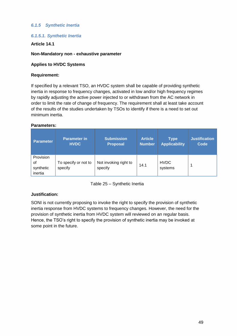
6.1.5 Synthetic Inertia
6.1.5.1. Synthetic Inertia
Article 14.1
Non-Mandatory non - exhaustive parameter
Applies to HVDC Systems
Requirement:
If specified by a relevant TSO, an HVDC system shall be capable of providing synthetic
inertia in response to frequency changes, activated in low and/or high frequency regimes
by rapidly adjusting the active power injected to or withdrawn from the AC network in
order to limit the rate of change of frequency. The requirement shall at least take account
of the results of the studies undertaken by TSOs to identify if there is a need to set out
minimum inertia.
Parameters:
Parameter Parameter in
HVDC
Submission
Proposal
Article
Number
Type
Applicability
Justification
Code
Provision
of
synthetic
inertia
To specify or not to
specify
Not invoking right to
specify 14.1
HVDC
systems 1
Table 25 – Synthetic Inertia
Justification:
SONI is not currently proposing to invoke the right to specify the provision of synthetic
inertia response from HVDC systems to frequency changes. However, the need for the
provision of synthetic inertia from HVDC system will reviewed on an regular basis.
Hence, the TSO’s right to specify the provision of synthetic inertia may be invoked at
some point in the future.
50
6.1.5.2. Synthetic Inertia
Article 14.2
Non - Mandatory non- exhaustive parameter
Applies to HVDC Systems
Requirement:
The principle of this control system and the associated performance shall be agreed
between the relevant TSO and the HVDC system owner.
Parameters:
Parameter Parameter in
HVDC
Submission
Proposal
Article
Number
Type
Applicability
Justification
Code
Agreement of
control system
and associated
parameters
To be agreed
between the
relevant TSO
and the HVDC
system owner
Not invoking right to
specify 14.2
HVDC
Systems 3
Table 26 – Synthetic Inertia
Justification:
SONI is not currently proposing to invoke the right to specify the provision of synthetic
inertia response from HVDC systems to frequency changes. However, the need for the
provision of synthetic inertia from HVDC system will reviewed on an regular basis.
Hence, the TSO’s right to specify the provision of synthetic inertia may be invoked at
some point in the future.
51
6.2 Voltage Theme
The non-exhaustive and non-mandatory voltage parameters cover a number of different
requirements. The following sub-themes are discussed in the next sections:
Voltage ranges
Reactive power capability
Priority to active or reactive power
Short-circuit requirements
Fault-ride-through
Power Quality
52
6.2.1. Voltage Ranges
6.2.1.1 Nominal Operational Voltage Range – Transmission System
Article 18.1:
Mandatory exhaustive parameter selection
Applies to HVDC converter stations
Requirement:
Without prejudice to Article 25, an HVDC converter station shall be capable of staying
connected to the network and capable of operating at HVDC system maximum current,
within the ranges of the network voltage at the connection point, expressed by the
voltage at the connection point related to reference 1 pu voltage, and the time periods
specified in Tables 4 and 5, Annex III. The establishment of the reference 1 pu voltage
shall be subject to coordination between the adjacent relevant system operators.
Parameters:
Parameter Parameter in
HVDC
Submission
Proposal
Article
Number
Type
Applicability
Justification
Code
110 kV 0.9 pu – 1.118 pu
(unlimited)
0.9 pu – 1.118 pu
(unlimited)
18.1
(Annex III
Table 3)
HVDC
Converter
stations
1
275 kV 0.9 pu – 1.118 pu
(unlimited)
0.9 pu – 1.118 pu
(unlimited)
18.1
(Annex III
Table 3)
HVDC
Converter
stations
1
400 kV 0.9 pu – 1.05 pu
(unlimited)
0.9 pu – 1.05 pu
(unlimited)
18.1
(Annex III
Table 4)
HVDC
Converter
stations
1
Table 27 – Voltage ranges for HVDC Converter Stations
Justification:
Included for information purposes only.
53
6.2.1.2 Nominal Operational Voltage Range – DC-Connected PPM
Article 40.1(a):
Mandatory exhaustive parameter selection
Applies to DC – connected PPMs
Requirement:
With respect to voltage ranges:
(a) a DC-connected power park module shall be capable of staying connected to
the remote-end HVDC converter station network and operating within the
voltage ranges (per unit), for the time periods specified in Tables 9 and 10,
Annex VII. The applicable voltage range and time periods specified are
selected based on the reference 1 pu voltage
Parameters:
Parameter Parameter in
HVDC
Submission
Proposal
Article
Number
Type
Applicability
Justification
Code
110 kV/
275 kV
0.85 pu – 0.9 pu
(60 minutes)
0.85 pu – 0.9 pu
(60 minutes) Article
40.1 (a)
(ANNEX
VII Table
DC-connected
PPMs 3
0.9 pu – 1.118 pu
(unlimited)
0.9 pu – 1.118 pu
(unlimited)
DC-connected
PPMs 3
1.118 pu – 1.15 pu
(60 minutes) Not allowed
DC-connected
PPMs 3
400 kV
0.85 pu – 0.9 pu
(60 minutes)
0.9 pu – 1.05 pu
(unlimited) Article
40.1 (a)
(ANNEX
VII Table
10)
DC-connected
PPMs 3
0.9 pu – 1.05 pu
(unlimited)
0.9 pu – 1.05 pu
(unlimited)
DC-connected
PPMs 3
1.05 pu – 1.15 pu
(unlimited) Not allowed
DC-connected
PPMs 3
Table 28 –voltage ranges for DC-connected PPMs
Justification:
Included for information purposes only.
54
6.2.1.3 Nominal Operational Voltage Range – Transmission System
Article 48.1(a):
Mandatory exhaustive parameter selection
Applies to remote-end HVDC converter stations
Requirement:
With respect to voltage ranges:
(a) a remote-end HVDC converter station shall be capable of staying connected to
the remote-end HVDC converter station network and operating within the voltage
ranges (per unit) and time periods specified in Tables 12 and 13, Annex VIII. The
applicable voltage range and time periods specified are selected based on the
reference 1 pu voltage;
Parameters:
Parameter Parameter in
HVDC
Submission
Proposal
Article
Number
Type
Applicability
Justification
Code
110 kV/
275 kV
0.85 pu – 0.9 pu
(60 minutes)
0.85 pu – 0.9 pu
(60 minutes) Article
40.1 (a)
(ANNEX
VII Table
9) Remote end
HVDC-
Converter
Stations
3
0.9 pu – 1.10 pu
(unlimited)
0.9 pu – 1.10 pu
(unlimited) 3
1.10 pu – 1.12 pu Case by case 3
1.12 pu – 1.15 pu Not allowed 3
400 kV
0.85 pu – 1.05 pu
(60 minutes)
0.85 pu – 0.9 pu (60
minutes) Article
40.1 (a)
(ANNEX
VII Table
10)
3
0.9 pu – 1.05 pu
(unlimited)
0.9 pu – 1.05 pu
(unlimited) 3
1.05 pu – 1.15 pu Not allowed 3
Table 29 – Voltage ranges for remote end HVDC converter stations
Justification:
The voltage capabilities of the remote end may be limited by the switchgear specification.
It is therefore determined that voltage time scales above 1.10 pu shall be determined on
a case-by-case basis.
55
6.2.1.4 Wider Operational Voltage Range and Longer Minimum Times for DC-
Connected Power Park Modules
Article 40.1(b):
Non-Mandatory non-exhaustive parameter selection
Requirement:
With respect to voltage ranges:
(b) wider voltage ranges or longer minimum times for operation can be agreed
between the relevant TSO and the DC-connected power park module owner
to ensure the best use of the technical capabiliites of a DC-connected power
park module if needed to preserve or to restore system security. If wider
voltage ranges or longer minimum times for operation are economically and
technically feasible, the DC-connected power park module owner shall not
unreasonably without consent.
Parameters:
Parameter Parameter in
HVDC
Submission
Proposal
Article
Number
Type
Applicability
Justification
Code
Wider
voltage
ranges
and longer
minimum
times
Not specified Site specific 40.1 (b) DC connected
PPMs 3
Table 30 – Wider Operational Voltage Range and Longer Minimum Times for DC-
Connected Power Park Modules
Justification:
The specification of these parameters would occur in consultation with the DC connected
power park module owner, during the connection application stage.
56
6.2.1.5 Wider Voltage Ranges or Longer Minimum Times
Article 48.1(b):
Non-Mandatory non-exhaustive parameter selection
Applies to DC-Connected Power Park Modules
Requirement:
With respect to voltage ranges:
(b) wider voltage ranges or longer minimum times for operation may be agreed
between the relevant system operator, in coordination with the relevant TSO, and
the DC-connected power park module owner in accordance with Article 40
Parameters:
Parameter Parameter in
HVDC
Submission
Proposal
Article
Number
Type
Applicability
Justification
Code
Wider
Voltage
Ranges
and
Longer
Minimum
Times
Not specified Site specific 48.1 (b)
DC –
Connected
PPMs
3
Table 31 – Wider Voltage Ranges or Longer minimum times
Justification:
The specification of these parameters would require a relevant system operator to be in
place. This would occur during the connection application stage.
57
6.2.1.6 Automatic Disconnection Due to Voltage Level
6.2.1.6.1 Automatic Disconnection Due to Voltage Level for HVDC Converter
stations
Article 18.3:
Mandatory exhaustive parameter selection
Applies to HVDC Converter Stations
Requirement:
An HVDC converter station shall be capable of automatic disconnection at connection
point voltage specified by the relevant system operator, in coordination with the relevant
TSO. The terms and settings for automatic disconnection shall be agreed between the
relevant system operator, in coordination with the relevant TSO, and HVDC system
owner.
Parameters:
Parameter Parameter in
HVDC
Submission
Proposal
Article
Number
Type
Applicability
Justification
Code
Minimum
Voltage below
which Module
will automatic
disconnect
Not specified Not Allowed 18.3
HVDC
Converter
Stations
3
Maximum
Voltage above
which Module
will automatic
disconnect
Not specified Not Allowed 18.3
HVDC
Converter
Stations
3
Table 32 – Automatic disconnection due to voltage level for HVDC Converter stations
Justification:
The current Grid Code does not stipulate voltage thresholds which allow for automatic
disconnection. The TSO invokes the right to prohibit automatic disconnection from the
Transmission System.
The HVDC converter station is not allowed to automatically disconnect from the system
within the normal operating voltage range or fault ride through parameters. Beyond that,
protection settings for undervoltage protection would be determined on a case by case.
58
6.2.1.6.2 Automatic Disconnection Due to Voltage Level – DC-connected PPM
Article 40.1(c):
Mandatory non-exhaustive parameter selection
Applies to DC-Connected Power Park Modules
Requirement:
With respect to voltage ranges:
(c) for DC-connected power park modules which have an HVDC interface point
to the remote-end HVDC converter station network, the relevant system
operator, in coordination with the relevant TSO may specify voltages at the
HVDC interface point at which a DC-connected power park module shall be
capable of automatic disconnection. The terms and settings for automatic
disconnection shall be agreed between the relevant system operator, the
relevant TSO and the DC-connected power park module owner.
Parameters:
Parameter Parameter in
HVDC
Submission
Proposal
Article
Number
Type
Applicability
Justification
Code
Minimum
Voltage below
which Module
will automatic
disconnect
Not specified Not allowed 40.1 c
DC-
connected
PPMs
3
Maximum
Voltage above
which Module
will automatic
disconnect
Not specified Not allowed 40.1 c DC-connected
PPM s 3
Table 33 – Automatic disconnection due to voltage level for DC-Connected Power Park
Modules
Justification:
This proposal is aligned with the RfG proposals.
The current Grid Code does not stipulate voltage thresholds which allow for automatic
disconnection. The TSO invokes the right to prohibit automatic disconnection from the
Transmission System.
59
6.2.2 Reactive power capability
6.2.2.1 Reactive power capability
6.2.2.1.1 Reactive Power Capability at Maximum Capacity: U-Q/Pmax Profiles
Article 20.1:
Mandatory non-exhaustive parameter selection
Applies to HVDC converter stations
Requirement:
The relevant system operator, in coordination with the relevant TSO, shall specify the
reactive power capability requirements at the connection points, in the context of varying
voltage. The proposal for those requirements shall include a U-Q/Pmax-profile, within the
boundary of which the HVDC converter station shall be capable of providing reactive
power at both its maximum Import and maximum Export HVDC active power
transmission capacity.
The diagram below represents boundaries of the U-Q/Pmax-profile with U being the
voltage at the connection points expressed by the ratio of its actual value to its reference
1 pu value in per unit, and Q/Pmax the ratio of the reactive power to the maximum HVDC
active power transmission capacity. The figure below shows the reactive power
requirement boundaries. The position, size and shape of the inner envelope are
indicative.
The voltage range of the inner envelop is expressed by the minimal (umin) and maximum
(umax) voltage in per unit. The Range of Q/Pmax is expressed by the maximum import
reactive power (Qmin/Pmax) and the maximum export reactive power (Qmax/Pmax) capability
in per unit.
60
Parameters:
Parameter Parameter
in HVDC
Parameter in
HVDC (outer
envelope)
Proposal
(Inner
Envelope)
Article
Number
Type
Applicabilit
y
Justification
Code
110 kV to
300 kV
umin 0.85 pu 0.9 pu 20.1
(Annex VII
Table 9)
HVDC
Converter
stations
3
umax 1.15 pu 1.118 pu
HVDC
Converter
stations
3
Qmin/Pmax
(lead) -0.5 pu -0.33 pu
20.1
(Annex VII
Figure 7)
HVDC
Converter
stations
3
Qmax/Pmax
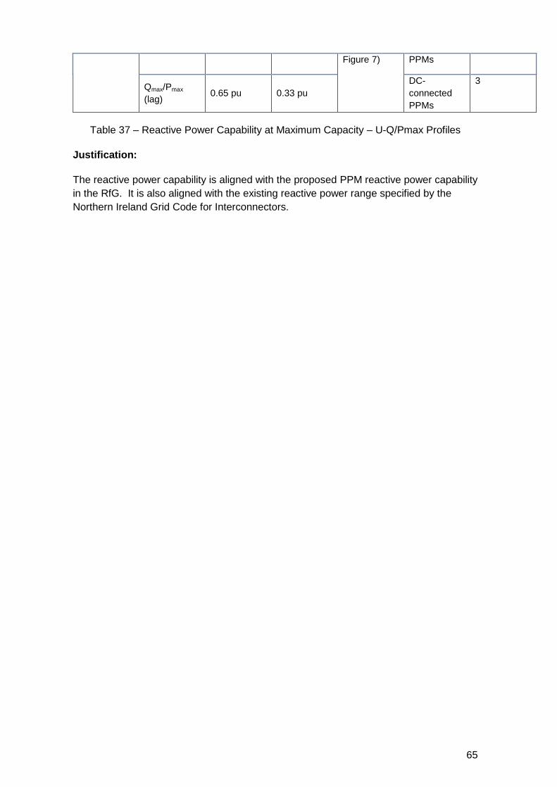
(lag) 0.65 pu 0.33 pu
HVDC
Converter
stations
3
300 kV to
400 kV
umin 0.85 pu 0.9 pu 20.1
(Annex VII
Table 10)
HVDC
Converter
stations
3
umax 1.15 pu 1.05 pu
HVDC
Converter
stations
3
Qmin/Pmax
(lead) -0.5 pu -0.33 pu
20.1
(Annex VII
Figure 7)
HVDC
Converter
stations
3
Qmax/Pmax
(lag) 0.65 pu 0.33 pu
HVDC
Converter
stations
3
Table 34 - Reactive Power Capability at Maximum Capacity: U-Q/Pmax Profiles
Justification:
The range of reactive power capability is as per the current Grid Code requirements for
wind farm power stations and aligned with the proposed requirements for PPMs in the
RfG consultation.
The voltage (umin and umax) ranges are aligned with the normal operating voltage ranges
within which the HVDC converter station shall stay connected to the network and
operate normally article 18.1 and Annex III Table 4 or Table 5).
61
6.2.2.1.2 Time to Achieve Target Value within P-Q/Pmax Profile
Article 20.3:
Mandatory non-exhaustive parameter selection
Applies to HVDC Systems
Requirement:
An HVDC system shall be capable of moving to any operating point within its U-Q/Pmax
profile in timescales specified by the relevant system operator in coordination with the
relevant TSO.
Parameters:
Parameter Parameter in
HVDC
Submission
Proposal
Article
Number
Type
Applicability
Justification
Code
Time to
achieve
target
value
Not specified
Without undue delay
but at least within
120 seconds
20.3 HVDC
Systems 1
Table 35 – Time to achieve target value within P-Q/Pmax Profile
Justification:
The time to achieve the target value is as per the current requirement set out in the
Scheduling and Dispatch Code Appendix B (SDC2.B.8) of the Grid Code for centrally
dispatched generating units. These units are being dispatched via the TSO electronic
interface program (EDIL); however, the same time period will apply for units being
dispatched via set point control.
62
6.2.2.1.3 Reactive Power Capability below Maximum Capacity: P-Q/Pmax Profiles
Article 20.4:
Mandatory exhaustive parameter selection
Applies to HVDC Converter Stations
Requirement:
When operating at an active power output in the range of maximum Import (𝑃𝑀𝐼𝐶𝑚𝑎𝑥)and
maximum Export (𝑃𝑀𝐸𝐶𝑚𝑎𝑥) HVDC active power transmission capacity, the HVDC converter
station shall be capable of operating in every possible operating point, as specified by
the relevant system operator in coordination with the relevant TSO and in accordance
with the reactive power capability set out by the U-Q/Pmax profile specified in Article 20
paragraphs 1 to 3 (see section 6.2.2.1.1 and 6.2.2.1.2).
Parameters:
Parameter Parameter
in HVDC
Parameter
in HVDC
Submission
Proposal
Article
Number
Type Applicability
Justification
Code
110 kV to
300 kV
pMIC 1.0 p.u. 1.0 p.u 20.4 HVDC Converter
Stations
3
pMEC 1.0 p.u. 1.0 p.u. 20.4 HVDC Converter
Stations
3
Qmin/Pmax
(lead) -0.5 p.u. -0.33 p.u. 20.4
HVDC Converter
Stations
3
Qmax/Pmax
(lag) 0.65 p.u. 0.33 p.u. 20.4
HVDC Converter
Stations
3
300 kV to
400 kV
pMIC 1.0 p.u. 1.0 p.u. 20.4 HVDC Converter
Stations
3
pMEC 1.0 p.u. 1.0 p.u. 20.4 HVDC Converter
Stations
3
Qmin/Pmax
(lead) -0.5 p.u. -0.33 p.u. 20.4
HVDC Converter
Stations
3
Qmax/Pmax
(lag) 0.65 p.u. 0.33 p.u. 20.4
HVDC Converter
Stations
3
Table 36 – Reactive Power Capability below Maximum Capacity: P-Q/Pmax Profiles
Justification:
HVDC is not included in the current SONI Grid Code. The reactive power parameters for
PMIC<P<PMEC are as per the current Northern Ireland Grid Code requirements.
63
6.2.2.1.4 Reactive Power Capability at Maximum Capacity: U-Q/Pmax Profiles
Article 40.2(b)(i):
Mandatory exhaustive parameter selection
Applies to DC-Connected Power Park Modules
Requirement:
With respect to reactive power capability for DC-connected power park modules:
(b) DC-connected power park modules shall fulfil the following requirements
relating to voltage stability either at the time of connection or subsequently,
according to the agreement as referred to in point (a):
(i) with regard to reactive power capability at maximum HVDC active power
transmission capacity, DC-connected power park modules shall meet the
reactive power provision capability requirements specified by the relevant
system operator, in coordination with the relevant TSO, in the context of
varying voltage. The relevant system operator shall specify a U-Q/Pmax-profile
that may take any shape with ranges in accordance with Table 11, Annex VII,
within which the DC-connected power park module shall be capable of
providing reactive power at its maximum HVDC active power transmission
capacity. The relevant system operator, in coordination with the relevant
TSO, shall consider the long term development of the network when
determining these ranges, as well as the potential costs for power park
modules of delivering the capability of providing reactive power production at
high voltages and reactive power consumption at low voltages.
If the Ten-Year Network Development Plan developed in accordance with
Article 8 of Regulation (EC) No 714/2009 or a national plan developed and
approved in accordance with Article 22 of Directive 2009/72/EC specifies that
a DC-connected power park module will become AC-connected to the
synchronous area, the relevant TSO may specify that either:
— the DC-connected power park module shall have the capabilities
prescribed in Article 25(4) of Regulation (EU) 2016/631 for that
synchronous area installed at the time of initial connection and
commissioning of the DC-connected power park module to the
AC-network; or
— the DC-connected power park module owner shall demonstrate to,
and then reach agreement with, the relevant system operator and
the relevant TSO on how the reactive power capability prescribed
in Article 25(4) of Regulation (EU) 2016/631 for that synchronous
area will be provided in the event that the DC-connected power
park module becomes AC-connected to the synchronous area.
U-Q/Pmax-profile of a DC-connected power park module at the connection point. The
diagram represents boundaries of a U-Q/Pmax-profile of the voltage at the connection
point, expressed by the ratio of its actual value to its reference 1 pu value in per unit,
against the ratio of the reactive power (Q) to the maximum capacity (Pmax). The position,
size and shape of the inner envelope are indicative.
64
The voltage range of the inner envelope is expressed by the minimal (umin) and
maximum (umax) voltage in per unit. The Range of Q/Pmax is expressed by the maximum
import reactive power (Qmin/Pmax) and the maximum export reactive power (Qmax/Pmax)
capability in per unit.
Parameters:
Parameter Parameter
in HVDC
Parameter
in HVDC
(outer
envelope)
Proposal
(Inner
Envelope)
Article
Number
Type
Applicability
Justification
Code
110 kV to
300 kV
umin 0.85 pu 0.9 pu 40.2 (b) (i)
(Annex VII
Table 9)
DC-
connected
PPMs
3
umax 1.15 pu 1.118 pu
DC-
connected
PPMs
3
Qmin/Pmax
(lead) -0.5 pu -0.33 pu
40.2 (b) (i)
(Annex VII
Figure 7)
DC-
connected
PPMs
3
Qmax/Pmax
(lag) 0.65 pu 0.33 pu
DC-
connected
PPMs
3
300 kV to
400 kV
umin 0.85 pu 0.85 pu 40.2 (b) (i)
(Annex VII
Table 10)
DC-
connected
PPMs
3
umax 1.15 pu 1.05 pu
DC-
connected
PPMs
3
Qmin/Pmax
(lead) -0.5 pu -0.33 pu
40.2 (b) (i)
(Annex VII
DC-
connected
3
65
Figure 7) PPMs
Qmax/Pmax
(lag) 0.65 pu 0.33 pu
DC-
connected
PPMs
3
Table 37 – Reactive Power Capability at Maximum Capacity – U-Q/Pmax Profiles
Justification:
The reactive power capability is aligned with the proposed PPM reactive power capability
in the RfG. It is also aligned with the existing reactive power range specified by the
Northern Ireland Grid Code for Interconnectors.
66
6.2.2.1.5 Reactive Power Capability at Maximum Capacity: U-Q/Pmax Profiles
Article 48.2(a) and (b):
Mandatory non- exhaustive parameter selection
Applies to HVDC converter stations
Requirement:
A remote-end HVDC converter station shall fulfil the following requirements referring to
voltage stability, at the connection points with regard to reactive power capability:
(a) the relevant system operator, in coordination with the relevant TSO shall specify
the reactive power provision capability requirements for various voltage levels. In
doing so, the relevant system operator, in coordination with the relevant TSO
shall specify a U-Q/Pmax-profile of any shape and within the boundaries of which
the remote-end HVDC converter station shall be capable of providing reactive
power at its maximum HVDC active power transmission capacity.
(b) the U-Q/Pmax-profile shall be specified by each relevant system operator, in
coordination with the relevant TSO. The U-Q/Pmax-profile shall be within the
range of Q/Pmax and steady-state voltage specified in Table 14, Annex VIII, and
the position of the U-Q/Pmax-profile envelope shall lie within the limits of the
fixed outer envelope specified in Annex IV. The relevant system operator, in
coordination with the relevant TSO, shall consider the long term development of
the network when determining these ranges.
Parameters:
Parameter Parameter
in HVDC
Parameter
in HVDC
(outer
envelope)
Proposal
(Inner
Envelope)
Article
Number
Type
Applicability
Justification
Code
110 kV to
300 kV
umin 0.85 pu 0.9 pu
40.2 (b) (i)
(Annex VII
Table 9)
DC-
connected
PPMs
3
umax 1.15 pu 1.118 pu
3
Qmin/Pmax
(lead) -0.5 pu -0.33 pu
40.2 (b) (i)
(Annex VII
Figure 7)
3
Qmax/Pmax
(lag) 0.65 pu 0.33 pu
3
300 kV to
400 kV
umin 0.85 pu 0.85 pu
40.2 (b) (i)
(Annex VII
Table 10)
3
67
umax 1.15 pu 1.05 pu
3
Qmin/Pmax
(lead) -0.5 pu -0.33 pu
40.2 (b) (i)
(Annex VII
Figure 7)
3
Qmax/Pmax
(lag) 0.65 pu 0.33 pu
3
Table 38 - Reactive Power Capability at Maximum Capacity: U-Q/Pmax Profiles
Justification:
The reactive power capability is aligned with the proposed PPM reactive power capability
in the RfG. It is also aligned with the existing reactive power range specified for
Interconnectors in the Northern Ireland Grid Code.
68
6.2.2.2 Reactive Power Mode
6.2.2.2.1 Standard Reactive Power Control Mode for HVDC Converter Stations
Article 22.1:
Mandatory exhaustive parameter selection
Applies to HVDC converter stations
Requirement:
An HVDC converter station shall be capable of operating in one or more of the three
following control modes, as specified by the relevant system operator in coordination
with the relevant TSO:
a) voltage control mode;
b) reactive power control mode;
c) power factor control mode.
Parameters:
Parameter Parameter in
HVDC
Submission
Proposal
Article
Number
Type
Applicability
Justification
Code
Voltage Not specified Invoke the right to
specify
Article
22.1
HVDC
Converter
stations
3
Reactive
Power Not specified
Invoke the right to
specify Article
22.1
HVDC
Converter
stations
3
Power
Factor Not specified
Invoke the right to
specify Article
22.1
HVDC
Converter
stations
3
Table 39 - Standard Reactive Power Control Mode for HVDC Converter Stations
Justification:
HVDC is not included in current draft of SONI Grid Code.
As much of the capacity of conventional generation becomes replaced by HVDC
systems, the services that were previously provided by those generators, will need to be
provided by the HVDC systems.
69
6.2.2.2.2 Customised Reactive Power Control Mode for HVDC Converter Stations
Mandatory non-exhaustive parameter selection
Applies to HVDC Converter Stations
Requirement:
Article 22.2:
An HVDC converter station shall be capable of operating in additional control modes
specified by the relevant system operator in coordination with the relevant TSO.
Parameters:
Parameter Parameter in
HVDC
Submission
Proposal
Article
Number
Type
Applicability
Justification
Code
Customis
ed control
mode
Not specified Site specific Article
22.2
HVDC
Converter
stations
3
Table 40 - Customised Reactive Power Control Mode for HVDC Converter stations
Justification:
During the connection offer process, additional reactive power control modes may be
specified for the HVDC converter station in order to avoid limiting future opportunities.
Hence, additional control modes are customised and therefore site-specific. HVDC
converter station owner and the relevant system operator, in coordination with the
relevant TSO, shall agree on the parameters and settings of additional control modes.
70
6.2.2.2.3 Voltage Control Mode
Mandatory non-exhaustive parameter selection
Applies to HVDC Converter Stations
Requirement:
Article 22.3:
For the purposes of voltage control mode, each HVDC converter station shall be capable
of contributing to voltage control at the connection point utilising its capabilities, while
respecting Articles 20 and 21, in accordance with the following control characteristics:
(a) a set point voltage at the connection point shall be specified to cover a specific
operation range, either continuously or in steps, by the relevant system operator,
in coordination with the relevant TSO;
(b) the voltage control may be operated with or without a deadband around the set
point selectable in a range from zero to +/– 5 % of reference 1 pu network
voltage. The deadband shall be adjustable in steps as specified by the relevant
system operator in coordination with the relevant TSO;
(c) following a step change in voltage, the HVDC converter station shall be capable
of:
(i) achieving 90 % of the change in reactive power output within a time t1
specified by the relevant system operator in coordination with the relevant
TSO. The time t1 shall be in the range of 0.1-10 seconds; and
(ii) settling at the value specified by the operating slope within a time t2
specified by the relevant system operator in coordination with the relevant
TSO. The time t2 shall be in the range of 1-60 seconds, with a specified
steady-state tolerance given in % of the maximum reactive power.
(d) voltage control mode shall include the capability to change reactive power output
based on a combination of a modified set point voltage and an additional
instructed reactive power component. The slope shall be specified by a range
and step specified by the relevant system operator in coordination with the
relevant TSO.
71
Parameters:
Parameter Parameter in
HVDC
Submission
Proposal
Article
Number
Type
Applicability
Justification
Code
Voltage set point Not specified continuous 22.3 (a)
HVDC
Converter
Stations
3
Steps to adjusted
deadband Not specified Site specific 22.3 (b)
HVDC
Converter
Stations
3
t1 = time within which
90% of the change in
reactive power is
reached
0,1 – 10 sec 1 22.3 (c)
(i)
HVDC
Converter
Stations
3
t2 = time within which
100% of the change
in reactive power is
reached
1 – 60 sec
5
(PPM
requirements
from RfG)
22.3 (c)
(ii)
HVDC
Converter
Stations 3
Steady state
tolerance Not specified 5%
22.3 (c)
(ii)
HVDC
Converter
Stations
3
Range and step of
slope Not specified Site specific 22.3 (d)
HVDC
Converter
Stations
3
Table 41 - Voltage Control Mode
Justification:
The voltage set point shall be capable to cover continuously the normal operational
voltage range (article 18.1 and Annex III Table 4 and Table 5).
The TSO invokes the right to specify the settings for a dead band during the connection
offer process.
The time t1 within which 90% of the change in reactive power is reached is set to 1
second. The proposed parameter for the Time t1 is aligned with the existing
requirements for an Interconnector within the Northern Ireland Grid Code.
The time t2 to achieve 100% of the change in reactive power is set to 5 seconds. The
proposed parameter is aligned with the proposal within the RfG for PPM.
72
6.2.2.2.4 Reactive Power Control Mode
Article 22.4:
Mandatory non-exhaustive parameter selection
Applies to HVDC Systems
Requirement:
With regard to reactive power control mode, the relevant system operator shall specify a
reactive power range in MVAr or in % of maximum reactive power, as well as its
associated accuracy at the connection point, using the capabilities of the HVDC system,
while respecting Articles 20 and 21.
Parameters:
Parameter Parameter in
HVDC
Submission
Proposal
Article
Number
Type
Applicability
Justification
Code
Maximum
Reactive
Power
Range
Not specified Site specific 22.4 HVDC
Systems 3
Accuracy
of
Reactive
Power
Not specified 5% 22.4 HVDC
Systems 3
Table 42 – Reactive Power Control Mode
Justification:
During the connection offer process any limits to reactive power exchange with the
network at the connection point resulting from control of reactive power in reactive power
control mode will be identified, and the associated required accuracy. The limits are
dependent on the location of the connection of the HVDC converter station within the AC
system and so are site specific.
73
6.2.2.2.5 Power Factor Control Mode
Article 22.5:
Mandatory non-exhaustive parameter selection
Applies to HVDC Converter Stations
Requirement:
For the purposes of power factor control mode, the HVDC converter station shall be
capable of controlling the power factor to a target at the connection point, while
respecting Articles 20 and 21. The available set points shall be available in steps no
greater than a maximum allowed step specified by the relevant system operator.
Parameters:
Parameter Parameter in
HVDC
Submission
Proposal
Article
Number
Type
Applicability
Justification
Code
Maximum
Allowed
Step
Change in
Power
Factor
Not specified Site specific 22.5
HVDC
Converter
stations
3
Maximum
Set Point
Steps
Not Specified 0.01 pu
(PowerFactor) 22.5
HVDC
Converter
stations
3
Table 43 – Power Factor Control Mode
Justification:
Site specific, depending on the interaction of the HVDC converter station with the
network at the connection point.
During the connection offer process any limits to the allowed step change in power factor
will be identified. The limits are dependent on the location of the connection of the HVDC
converter station within the AC system and so are site specific.
The maximum set point steps have been chosen to provide an acceptable resultant
change in voltage at the connection point, regardless of where the connection point is on
the AC network.
74
6.2.2.2.6 Equipment to Select Control Modes Remotely
Article 22.6:
Mandatory non-exhaustive parameter selection
Applies to HVDC Converter Stations
Requirement:
The relevant system operator in coordination with the relevant TSO shall specify any
equipment needed to enable the remote selection of control modes and relevant set
points.
Parameters:
Parameter Parameter in
HVDC
Submission
Proposal
Article
Number
Type
Applicability
Justification
Code
Equipment Not specified Site specific 22.6
HVDC
Converter
Stations
3
Table 44 – Equipment to select control mode remotely
Justification:
At this point in time we leave this as site specific as technology develops. This parameter
may be further developed in future.
75
6.2.3 Reactive Power Exchanged with Network
6.2.3.1 Reactive Power Exchanged with the Network
Article 21.1:
Mandatory non-exhaustive parameter selection
Applies to HVDC Converter Stations
Requirement:
The HVDC system owner shall ensure that the reactive power of its HVDC converter
station exchanged with the network at the connection point is limited to values specified
by the relevant system operator in coordination with the relevant TSO.
Parameters:
Parameter Parameter in
HVDC
Submission
Proposal
Article
Number
Type
Applicability
Justification
Code
Maximum
Reactive
Power
Range
Not specified Site specific 21.1
HVDC
Converter
Stations
3
Table 45 – Reactive Power Exchanged with Network
Justification:
During the connection offer process any limits to reactive power exchange with the
network at the connection point will be identified. The limits are dependent on the
location of the connection of the HVDC converter station within the AC system and so
are site specific.
76
6.2.3.2 Maximum Tolerable Voltage Steps for Reactive Power Variation
Article 21.2:
Mandatory non-exhaustive parameter selection
Applies to HVDC Converter Stations
Requirement:
The reactive power variation caused by the reactive power control mode operation of the
HVDC converter station, referred to in Article 22(1), shall not result in a voltage step
(|Δ𝑢|) exceeding the allowed value at the connection point. The relevant system operator,
in coordination with the relevant TSO, shall specify this maximum tolerable voltage step
value.
Parameters:
Parameter Parameter in
HVDC
Submission
Proposal
Article
Number
Type
Applicability
Justification
Code
Maximum
Tolerable
Voltage
Step
Not specified As per TSSPS 21.2
HVDC
Converter
Stations
3
Table 46 – Maximum Tolerable Voltage Steps for Reactive Power Variation
Justification:
This will be equivalent to the switching of reactive power provider which depends on the
frequency of the operation. The Transmission System Security and Planning Standards
(TSSSPS) stipulates a limit for switching of 3%. However if frequent changes occur then
the TSSPS states that ER P28 could apply and a general limit of 1%.
77
6.2.4 Reactive Power Consumption of extra high voltage lines
6.2.4.1. Reactive Power Capability
Article 40.2(b)(ii)
Mandatory non-exhaustive parameter selection
Applies to DC-connected Power Park Modules
Requirement:
With respect to reactive power capability for DC-connected power park modules:
(b) DC-connected power park modules shall fulfil the following requirements relating
to voltage stability either at the time of connection or subsequently, according to
the agreement as referred to in point (a):
(ii) With regard to reactive power capability, the relevant system operator may
specify supplementary reactive power to be provided if the connection point
of a DC-connected power park module is neither located at the high-voltage
terminals of the step-up transformer to the voltage level of the connection
point nor at the alternator terminals, if no step-up transformer exists. This
supplementary reactive power shall compensate the reactive power
exchange of the high-voltage line or cable between the high-voltage terminals
of the step-up transformer of the DC-connected power park module or its
alternator terminals, if no step-up transformer exists, and the connection point
and shall be provided by the responsible owner of that line or cable.
Parameters:
Parameter Parameter in HVDC
Submission Proposal
Article Number
Type Applicability
Justification Code
Right to specify supplementary reactive power requirements when the connection point is remote
To specify or not to specify
TSOs reserve the right to specify
Article 40.2 (b) (ii)
DC-connected PPM
3
Table 47 – Reactive Power consumption of extra high voltage lines Justification: The TSO invoke the right to specify supplementary reactive power requirements for remote connection points in order to align with the supplementary reactive power requirements. Any supplementary reactive power compensation required to offset the reactive power demand of the line or cable between the connection point and HVDC converter station site will be identified during the connection offer process.
78
6.2.5 Priority to active or reactive power
6.2.5.1 Priority Given to Active or Reactive Power Contribution for HVDC Systems
Article 23:
Mandatory non-exhaustive parameter selection
Applies to HVDC Systems
Requirement:
Taking into account the capabilities of the HVDC system specified in accordance with
this regulation, the relevant TSO shall determine whether active power contribution or
reactive power contribution shall have priority during low or high voltage operation and
during faults for which fault-ride-through capability is required. If priority is given to
active power contribution, its provision shall be established within a time from the fault
inception as specified by relevant TSO.
Parameters:
Parameter Parameter in
HVDC
Submission
Proposal
Article
Number
Type
Applicability
Justification
Code
Prioritisation
requirements
during FRT
Active /
Reactive Active 23
HVDC
Systems 3
Table 48 – Priority given to Active or Reactive Power Contribution for HVDC Systems
Justification:
The proposal for HVDC converter station aligns with the requirements for PPM in the
current Grid Code which stipulates that priority shall always be given to the active power
response during and after faults within the capabilities of the PPM.
79
6.2.5.2 Priority Given to Active or Reactive Power Contribution for DC-connection
Power Park Modules
Article 40.3:
Mandatory non-exhaustive parameter selection
Applies to DC-Connected Power Park Modules
Requirement:
With regard to priority to active or reactive power contribution for DC-connected power
park modules, the relevant system operator, in coordination with the relevant TSO shall
specify whether active power contribution or reactive power contribution has priority
during faults for which fault-ride-through capability is required. If priority is given to active
power contribution, its provision shall be established within a time from the fault inception
as specified by the relevant system operator, in coordination with the relevant TSO.
Parameters:
Parameter Parameter in
HVDC
Submission
Proposal
Article
Number
Type
Applicability
Justification
Code
Prioritisation
requirement
s during FRT
Active/Reactive Active Article
40.3
DC-connected
PPMs 3
Table 49 – Priority Given to Active or Reactive Power Contribution for DC-Connected
Power Park modules
Justification:
The proposal aligns with the RfG consultation, which stipulated that priority should
always be given to the active power response during, and after faults within the
capabilities of the DC connected PPM.
80
6.2.6 Short-circuit requirements
6.2.6.1 Short Circuit – Fast Fault Current Injection for Symmetrical and
Asymmetrical Faults
Articles 19.1, 19.2 and 19.3
Non-Mandatory non-exhaustive parameter selection, with the exception of Articles
19.2 and 19.3 which are being made mandatory
Applies to HVDC Systems
Requirement:
Article 19.1:
If specified by the relevant system operator, in coordination with the relevant TSO, an
HVDC system shall have the capability to provide fast fault current at a connection point
in case of symmetrical (3-phase) faults.
Article 19.2:
Where an HVDC system is required to have the capability referred to in paragraph 1, the
relevant system operator, in coordination with the relevant TSO, shall specify the
following:
(a) how and when a voltage deviation is to be determined as well as the end of
the voltage deviation;
(b) the characteristics of the fast fault current;
(c) the timing and accuracy of the fast fault current, which may include several
stages.
Article 19.3:
The relevant system operator, in coordination the relevant TSO, may specify a
requirement for asymmetrical current injection in the case of asymmetrical (1-phase or 2-
phase) faults.
Parameters:
Parameter Parameter
in HVDC Submission Proposal
Article
Number
Type
Applicability
Justification
Code
Voltage threshold
for fast fault current
injection
Not
specified
During voltage dips i.e.
when the voltage is
below 0.9 p.u.
19.2 &
19.3
HVDC
Systems 3
End of the voltage
deviation
Not
specified
Once the voltage has
recovered to within
normal operating
voltage range
19.2 &
19.3 HVDC
Systems 3
the characteristics
of the fast fault
current, including
Not
specified
Reactive current
should be provided for
the duration of the
19.2 &
19.3 HVDC
Systems 3
81
the time domain for
measuring the
voltage deviation
and fast fault
current
voltage deviation within
the rating of the PPM
the timing and
accuracy of the fast
fault current, which
may include several
stages during a
fault and after its
clearance
Not
specified
Rise Time no greater
than 100ms and a
Settling Time no
greater than 300ms.
19.2 &
19.3
HVDC
Systems 3
Table 50 – Short – circuit – Fast Fault Current Injection for Symmetrical and
Asymmetrical Faults
Justification:
The fast fault current injection for symmetrical faults for HVDC converter station has been aligned with the fast fault current injection of PPM requirements according to RfG.
As proposed with the RfG, the fast fault current injection shall be provided during
Transmission System voltage dips.
The parameters chosen above align with the parameters in the Northern Ireland.
82
6.2.7 Fault – ride – through capability
6.2.7.1 Fault Ride Through Capability for HVDC Converter Stations
Article 25.1
Mandatory non-exhaustive parameter selection
Applies to HVDC Converter Stations
Requirement:
The relevant TSO shall specify, while respecting Article 18, a voltage-against time profile
as set out in Annex V and having regard to the voltage-against-time-profile specified for
power park modules according to Regulation (EU) 2016/631. This profile shall apply at
connection points for fault conditions, under which the HVDC converter station shall be
capable of staying connected to the network and continuing stable operation after the
power system has recovered following fault clearance. The voltage-against-time-profile
shall express a lower limit of the actual course of the phase-to-phase voltages on the
network voltage level at the connection point during a symmetrical fault, as a function of
time before (𝑡 < 0), during (0 ≤ 𝑡 ≤ 𝑡𝑐𝑙𝑒𝑎𝑟) and after (𝑡𝑐𝑙𝑒𝑎𝑟 < 𝑡 ≤ 𝑡𝑟𝑒𝑐2) the fault. Any
ride through period beyond 𝑡𝑟𝑒𝑐2 is in section or Article 18.
HVDC converter stations shall be capable of staying connected to the network and
continuing to operate stably after the power system has been disturbed by secured faults.
That capability shall be in accordance with a voltage-against-time profile at the
connection point for fault conditions in line the figure below.
Fault Ride Through Profile Example
The voltage-against-time-profile shall express a lower limit of the actual course of the
phase-to-phase voltages on the network voltage level at the connection point during a
symmetrical (Article 19.1) and asymmetrical (Article 19.3) fault, as a function of time
before, during and after the fault. The voltage-against-time-profile is defined by the
points 1 to 4 as follows:
83
Parameters:
Parameter
HVDC
Parameter
Range
Proposal Article
Number
Type
Applicability
Justification
Code
uret 0.00 – 0.3 pu 0.0 pu 25.1
HVDC
Converter
Stations
3
tclear 0.14 – 0.25 s 0.15 s 25.1
HVDC
Converter
Stations
3
urec1 0.25 – 0.85 pu 0.85 pu 25.1
HVDC
Converter
Stations
3
trec1 1.5 – 2.5 s 2.5 s 25.1
HVDC
Converter
Stations
3
urec2 0.85 – 0.9 pu 0.9 pu 25.1
HVDC
Converter
Stations
3
trec2 trec1 – 10.0 s 10.0 s 25.1
HVDC
Converter
Stations
3
Table 51 - Fault Ride Through Capability for HVDC Converter Stations
Justification:
The parameters chosen above are as closely aligned as possible within the range
provided to the previous proposals for a Power Park Module (within the RfG).
84
6.2.7.2 Voltage level the HVDC Converter Station Blocks
Article 25.4:
Non-Mandatory non- exhaustive parameter selection
Applies to HVDC Systems
Requirement:
The relevant TSO may specify voltages (Ublock) at the connection points under specific
network conditions whereby the HVDC system is allowed to block. Blocking means
remaining connected to the network with no active and reactive power contribution for a
time frame that shall be as short as technically feasible and which shall be agreed
between the relevant TSOs and the HVDC system owner.
Parameters:
Parameter Parameter in
HVDC
Submission
Proposal
Article
Number
Type
Applicability
Justification
Code
ublock Not specified Site specific Article
25.4
HVDC
Systems 3
Table 52 – Voltage Level the HVDC Converter Station Blocks
Justification:
The allowed blocking voltage would be determined following a set of system studies,
pertaining to the proposed connection point. Furthermore, evaluating this on a case-by-
case basis will allow advances to be incorporated.
85
6.2.7.3 Fault Ride Through Capability in case of asymmetrical faults
Article 25.6:
Mandatory non-exhaustive parameter selection
Applies to HVDC Systems
Requirement:
The relevant TSO shall specify fault-ride-through capabilities in case of asymmetrical
faults.
Parameters:
Parameter
HVDC
Parameter
Range
Proposal Article
Number
Type
Applicability
Justification
Code
uret 0.00 – 0.3 pu 0.0 pu 25.1
HVDC
systems
3
tclear 0.14 – 0.25 s 0.15 s 25.1
urec1 0.25 – 0.85 pu 0.85 pu 25.1
trec1 1.5 – 2.5 s 2.5 s 25.1
urec2 0.85 – 0.9 pu 0.9 pu 25.1
trec2 trec1 – 10.0 s 10.0 s 25.1
Table 53 – Fault Ride Through Capability in case of asymmetrical faults
Justification:
The parameters chosen above are as closely aligned as possible within the range
provided to the previous proposals for a Power Park Module (within the RfG).
86
6.2.7.4 Post Fault Active Power Recovery
Article 26:
Mandatory exhaustive parameter selection
Applies to HVDC Systems
Requirement:
The relevant TSO shall specify the magnitude and time profile of active power recovery
that the HVDC system shall be capable of providing, in accordance with Article 25
Parameters:
Parameter Parameter in
HVDC
Submission
Proposal
Article
Number
Type
Applicability
Justification
Code
when the
post-fault
active
power
recovery
begins,
based on a
voltage
criterion
Not specified un< 0.9 pu
26
HVDC
Systems
3
maximum
allowed
time for
active
power
recovery
Not specified 500ms/1s
26
HVDC
Systems
3
magnitude
and
accuracy
for active
power
recovery
Not specified 90%
26
HVDC
systems
3
Table 54 – Post Fault Active Power Recovery
Justification:
The proposals are aligned with the proposed Active Power Recovery for PPMs within the
RfG. These were in turn aligned to the existing requirements for WFPS within the SONI
Grid Code.
87
6.2.8 Power Quality
6.2.8.1 Power Quality for HVDC Systems
Article 24:
Mandatory non-exhaustive parameter selection
Applies to HVDC Systems
Requirement:
An HVDC system owner shall ensure that its HVDC system connection to the network
does not result in a level of distortion or fluctuation of the supply voltage on the network,
at the connection point, exceeding the level specified by the relevant system operator in
coordination with the relevant TSO. The process for necessary studies to be conducted
and relevant data to be provided by all grid users involved, as well as mitigating actions
identified and implemented, shall be in accordance with the process in Article 29.
Parameters:
Parameter Parameter in
HVDC
Submission
Proposal
Article
Number
Type
Applicability
Justification
Code
Level of
voltage
distortion
or
fluctuation
of the
supply
voltage at
the
connection
point
Not specified
ER G5/4-1
Harmonics
ER P28 Voltage
fluctuation
24 HVDC
Systems 3
Table 55 – Power Quality for HVDC Systems
Justification:
These are the limits as established by the Transmission System Security and Planning
Standards and align with the limits set in the Requirement for Generators and Demand
Connection Codes.
88
6.2.8.2 Power Quality for DC-connected PPMs
Article 44
Mandatory exhaustive parameter selection
Applies to DC-connected Power Park Modules
Requirement:
DC-connected power park modules owners shall ensure that their connection to the
network does not result in a level of distortion or fluctuation of the supply voltage on the
network, at the connection point, exceeding the level specified by the relevant system
operator, in coordination with the relevant TSO. The necessary contribution from grid
users to associated studies, including, but not limited to, existing DC-connected power
park modules and existing HVDC systems, shall not be unreasonably withheld. The
process for necessary studies to be conducted and relevant data to be provided by all
grid users involved, as well as mitigating actions identified and implemented, shall be in
accordance with the process in Article 29.
Parameters:
Parameter Parameter in
HVDC
Submission
Proposal
Article
Number
Type
Applicability
Justification
Code
Voltage and
distortion limits
To be specified
by the relevant
TSO
To be site specific 44 DC-connected
PPMs 3
Table 56 – voltage and distortion limits
Justification:
This requirement will need to be implemented on a site specific basis due to:
Varying station and/or HVDC system configurations
Compatibility with existing equipment
Operational constraints
89
6.2.8.3 Power Quality for remote-end HVDC Converter Stations
Article 50
Mandatory exhaustive parameter selection
Applies to Remote-end HVDC Converter stations
Requirement:
Remote-end HVDC converter station owners shall ensure that their connection to the
network does not result in a level of distortion or fluctuation of the supply voltage on the
network, at the connection point, exceeding the level allocated to them by the relevant
system operator, in coordination with the relevant TSO. The necessary contribution from
grid users to the associated studies shall not be unreasonably withheld, including from,
but not limited to, existing DC-connected power park modules and existing HVDC
systems. The process for necessary studies to be conducted and relevant data to be
provided by all grid users involved, as well as mitigating actions identified and
implemented shall be in accordance with the process provided for in Article 29.
Parameters:
Parameter Parameter in
HVDC
Submission
Proposal
Article
Number
Type
Applicability
Justification
Code
Voltage
and
distortion
limits
To be specified by
the relevant TSO To be site specific 50
Remote-end
HVDC
Convertor
stations
3
Table 57 – Power Quality for remote-end HVDC Converter Stations
Justification:
This requirement will need to be implemented on a site-specific basis due to: (a) Varying station and/or HVDC system configuration and types;
(b) Localised short circuit level
(c) Local modes of Oscillation
(d) Compatibility with existing equipment
90
6.3 System Restoration
The non-exhaustive and non-mandatory frequency parameters cover a number of
different requirements. The following sub-themes are discussed in the next sections:
Power Oscillation Damping Capability
System Restoration
91
6.3.1 Power Oscillation Damping Capability
6.3.1.1 Frequency range for oscillations
Article 30
Applies to HVDC Systems
Mandatory non - exhaustive parameter selection
Requirement:
The HVDC system shall be capable of contributing to the damping of power oscillations
in connected AC networks. The control system of the HVDC system shall not reduce the
damping of power oscillations. The relevant TSO shall specify a frequency range of
oscillations that the control scheme shall positively damp and the network conditions
when this occurs, at least accounting for any dynamic stability assessment studies
undertaken by TSOs to identify the stability limits and potential stability problems in their
transmission systems. The selection of the control parameter settings shall be agreed
between the relevant TSO and the HVDC system owner.
Parameters:
Parameter Parameter in HVDC Submission
Proposal
Article
Number
Type
Applicability
Justification
Code
Frequency range
for oscillations
To be specified by
the TSO Site specific 30 HVDC System 3
Table 58 – Frequency range for oscillations
Justification:
This requirement will need to be implemented on a site-specific basis due to: (e) Varying station and/or HVDC system configuration and types;
(f) Localised short circuit level
(g) Local modes of Oscillation
(h) Compatibility with existing equipment
92
6.3.1.2 SSTI Study requirements
Article 31.2
Mandatory non- exhaustive parameter selection
Applies HVDC Systems
Requirement:
The relevant TSO shall specify the necessary extent of SSTI studies and provide input
parameters, to the extent available, related to the equipment and relevant system
conditions in its network. The SSTI studies shall be provided by the HVDC system
owner. The studies shall identify the conditions, if any, where SSTI exists and propose
any necessary mitigation procedure. Member States may provide that the responsibility
for undertaking the studies in accordance with this Article lies with the TSO. All parties
shall be informed of the results of the studies.
Parameters:
Parameter Parameter in HVDC Submission
Proposal
Article
Number
Type
Applicability
Justification
Code
Specification of
extent of SSTI
and parameters
To be specified by
the TSO in due for
plant design
To be
specified on
a case by
case
31.2 HVDC System
Owners 3
Table 59 – SSTI Study Requirements
Justification:
The proposal is to specify these requirements on the case – by – case basis, taking into
considering:
The proximity of HVDC converter to power generation modules
The electrical characteristics of the local network
The torsional modes of existing generation in the vicinity
The characteristics of the HVDC converter
93
6.3.1.3 Relevant parties at a connection point
Article 31.3
Mandatory non-exhaustive parameter selection
Applies to relevant parties
Requirement:
All parties identified by the relevant TSO as relevant to each connection point, including
the relevant TSO, shall contribute to the studies and shall provide all relevant data and
models as reasonably required to meet the purposes of the studies. The relevant TSO
shall collect this input and, where applicable, pass it onto the party responsible for the
studies in accordance with article 10.
Parameters:
Parameter Parameter in
HVDC
Submission
Proposal
Article
Number
Type
Applicability
Justification
Code
Identify all parties
relevant at the
connection
point
In due time for
plant design
Develop
necessary process
for the
management of
date during the
implementation
phase
31.3
All parties
relevant
parties at the
connection
point
3
Table 60 – Relevant parties at a connection point
Justification:
It is proposed to develop the necessary process for the collection of the necessary inputs
and the management of this data during the implementation phase of the HVDC.
94
6.3.2 Blackstart
6.3.2.1 Procurement of Blackstart
Article 37.1
Non-mandatory being made mandatory
Applies to HVDC Systems
Requirement:
The relevant TSO may obtain a quote for black start capability from an HVDC system
owner.
Parameters:
Parameter Parameter in
HVDC
Submission
Proposal
Article
Number
Type
Applicability
Justification
Code
Obtain
quote for
black start
TSO to obtain Retain the existing
services process
37.1
HVDC
Systems 1
Table 61 – Procurement of Blackstart services
Justification:
The TSO currently has a procedure in place for the obtaining of services, such as black
start. It is proposed to retain the existing process.
95
6.3.2.2 Time frame and voltage limits to energise an AC busbar during blackstart
Article 37.2:
Non-mandatory being made mandatory
Applies to HVDC Systems with Black start capabilities
Requirement:
An HVDC system with black start capability shall be able, in case one converter station
is energised, to energise the busbar of the AC-substation to which another converter
station is connected, within a timeframe after shut down of limits set out in Article 11 and
within the voltage limits specified by the relevant TSO or as provided for in Article 18,
where applicable. Wider frequency and voltage ranges can be specified by the relevant
TSO where needed in order to restore system security.
Parameters:
Parameter Parameter in
HVDC
Submission
Proposal
Article
Number
Type
Applicability
Justification
Code
Time frame and
voltage limits to
energise the
AC busbar with
start, with wider
frequency and
voltage ranges
In due time for
plant design Site Specific 37.2
HVDC system
with black
start
capabilities
3
Table 62 – Time frame and voltage limits to energise an AC busbar during blackstart
Justification:
The proposal to specify this requirement as site – specific is to allow for a number of factors to be taken into consideration:
Varying nature blackstart situation
Availability of plant, including transmission plant during blackstart situation
Availability of staff during a blackstart situation
These elements are included as part of to the System Restoration plan.
96
6.3.2.3 Capacity and availability of black start capability
Article 37.3:
Non-mandatory being made mandatory
Applies to HVDC Systems
Requirement:
The relevant TSO and HVDC system owner shall agree on the capacity and availability
of the black start capability and the operational procedure.
Parameters:
Parameter Parameter in
HVDC
Submission
Proposal
Article
Number
Type
Applicability
Justification
Code
Capacity and
availability of
black start
To be agreed
between the
TSO and the
HVDC system
owners
To be agreed on a
case by case basis 37.3
HVDC
systems 1
Table 63 – Capacity and availability of blackstart capability
Justification:
The TSO is proposing to retain the current process of agreeing the capacity and
availability of the black start capability and the operational procedure on a case by case
basis, as this allows both the system needs and the HVDC system characteristics to be
taken into consideration.
97
6.4 Instrumentation, simulation models and protection
The non-exhaustive and non-mandatory frequency parameters cover a number of
different requirements. The following sub-themes are discussed in the next sections:
Interaction between HVDC Systems and other plant / equipment
Electrical Protection Schemes and settings
Synchronisation
Network characteristics
Output signals
Power Oscillations and damping capability
HVDC Robustness
Power Quality
98
6.4.1 Interaction between HVDC Systems and other plant / equipment
6.4.1.1 Interaction between HVDC Systems and other plant / equipment
Article 29.2
Mandatory non - exhaustive parameter selection
Applies to HVDC Systems
Requirement:
The studies shall be carried out by connecting the HVDC system owner with the
participation of all other parties identified by the TSOs as relevant to each connection
point. Member States may provide that the responsibility for undertaking the studies in
accordance with this Article lies with the TSO. All parties shall be informed of the results
of the studies.
Parameters:
Parameter Parameter in
HVDC
Submission
Proposal
Article
Number
Type
Applicability
Justification
Code
Specify study
required to
examine
interaction with
adjacent
equipment
TO be
specified by
TSO
Grid Code Appendix
A – Planning Data
requirements for
Users (other than the
DNO) connected to
the transmission
system only to be
modified to include
the relevant study
requirements and
parameters for
HVDC System
29.2 HVDC
Systems 3
Table 64 – Interaction between HVDC Systems and other plant / equipment
Justification:
Currently, Appendix A – Planning Data Requirements for Users (other than DNO)
connected to the transmission system only does not contain any data requirements or
parameters for HVDC system. It is proposed to modify the Appendix A to include the
necessary requirements and parameters including these required for purpose of system
and other studies.
99
6.4.1.2 Identification of all parties relevant to studies
Article 29.3
Mandatory non- exhaustive parameter selection
Applies to relevant parties
Requirement:
All parties identified by the relevant TSO as relevant to each connection point, including
the relevant TSO, shall contribute to the studies and shall provide all relevant data and
models as reasonably required to meet the purposes of the studies. The relevant TSO
shall connect this input and, where applicable, pass it on to the party responsible for the
studies in accordance with Article 10.
Parameters:
Parameter Parameter in
HVDC
Submission
Proposal
Article
Number
Type
Applicability
Justification
Code
All relevant
parties to
studies
Specify all other
relevant parties to
the study
TSO to develop
process for
identification of all
relevant parties
during the
implementation
phase.
29.3
All parties
relevant to
studies
3
Table 65 – Identification of all parties relevant to studies
Justification:
As part of the implementation phase, the TSO will develop a process for the identification
of all relevant parties, who must contribute to the study and provide all relevant
information, including all necessary models.
100
6.4.1.3 Models and information requirements
Article 29.4
Mandatory non-exhaustive parameter selection
Applies to HVDC Systems
Requirement:
The relevant TSO shall assess the result of the studies based on their scope and extent
as specified in accordance with paragraph 1. If necessary for the assessment, the
relevant TSO may request the HVDC system owner to perform further studies in line with
the scope and extent specified in accordance with paragraph 1.
Parameters:
Parameter Parameter in
HVDC
Submission
Proposal
Article
Number
Type
Applicability
Justification
Code
Model /
information for
in studies
To be specified
by the TSO Case by case basis 29.4
HVDC System
Owner 3
Table 66 – Models and information requirements
Justification:
The need for any further studies, in addition to those required under Article 29.2 and 29.3, will be determined on a case-by-case basis.
101
6.4.2 Electrical protection schemes and settings
6.4.2.1 Specification of Electrical protection schemes and settings
Article 34.1
Mandatory non - exhaustive parameter selection
Applies to HVDC Systems
Requirement:
The relevant system operator shall specify, in coordination with the relevant TSO, the
schemes and settings necessary to protect the network taking into account the
characteristics of the HVDC system. Protection schemes relevant for the HVDC system
and the network, and settings relevant for the HVDC system, shall be coordinated and
agreed between the relevant system operator, the relevant TSO and the HVDC system
owner. The protection schemes and settings for internal electrical faults shall be
designed so as not to jeopardise the performance of the HVDC system in accordance
with this Regulation.
Parameters:
Parameter Parameter in
HVDC
Submission
Proposal
Article
Number
Type
Applicability
Justification
Code
Specification of
protection
schemes and
settings
To be specified
by TSO Site specific 34.1
HVDC
Systems 3
Table 67 – Specification of electrical protection schemes and settings
Justification:
This requirement will need to be implemented on a site-specific basis due to: (a) Varying station and/or HVDC system configuration and types; and
(b) Compatibility with existing equipment
(c) Need for Special Protection Schemes
102
6.4.2.2 Agreement of Electrical protection schemes and settings
Article 34.3
Mandatory non - exhaustive parameter selection
Applies to HVDC Systems
Requirement:
Any changes to the protection schemes or their settings relevant to the HVDC system
and the network shall be agreed between the system operator, the relevant TSO and the
HVDC system owner before being implemented by the HVDC system owner.
Parameters:
Parameter Parameter in
HVDC
Submission
Proposal
Article
Number
Type
Applicability
Justification
Code
Agreement of
protection
schemes and
settings
To be agreed
between the
relevant TSO
and the HVDC
system owner
Necessary process
to be developed
during
implementation
phase.
34.3 HVDC
Systems 3
Table 68 – Agreement of Electrical protection schemes and settings
Justification:
The business process for the agreement of the necessary protection schemes and
settings between the TSO and aHVDC system owner will be developed as part of the
implementation phase of the HVDC code.
103
6.4.2.3 Agreement of Control schemes, including the necessary settings
Article 35.1
Mandatory non - exhaustive parameter selection
Applies to HVDC Systems
Requirement:
A control scheme, specified by the HVDC system owner consisting of different control
modes, including the settings of the specific parameters, shall be coordinated and
agreed between the relevant TSO, the relevant system operator and the HVDC system
owner.
Parameters:
Parameter Parameter in
HVDC
Submission
Proposal
Article
Number
Type
Applicability
Justification
Code
Control
scheme,
including
settings to be
agree between
the relevant
TSO and
HVDC system
owner.
To be agreed
between the
relevant TSO
and the HVDC
system owner
It will be necessary
to develop a process
during the
implementation
phase.
34.3 HVDC
Systems 3
Table 69 – Agreement of Control schemes
Justification:
The business process for the agreement of the necessary protection schemes and
settings between the TSO and the HVDC system owner will be developed as part of the
implementation phase of the HVDC.
104
6.4.2.4 Priority rating of protection and control for HVDC systems
Article 35.2
Non-mandatory being made mandatory
Applies to HVDC Systems
Requirement:
With regard to priority rating of protection and control, the HVDC system owner shall
organise its protection and control devices in compliance with the following priority
ranking, listed in decreasing order of importance, unless otherwise specified by the
relevant TSOs, in coordination with the relevant system operator:
(a) Network system and HVDC system protection;
(b) Active power control for emergency assistance;
(c) Synthetic inertia, if applicable;
(d) Automatic remedial actions as specified in Article 13(3);
(e) LFSM;
(f) FSM and frequency control; and
(g) Power gradient constraint.
Parameters:
Parameter Parameter in
HVDC
Submission
Proposal
Article
Number
Type
Applicability
Justification
Code
Priority
rating of
protection
and control
for HVDC
systems
Change to priority
order of protection
and control
Process
to be developed
during
implementation
phase.
35.2 HVDC
Systems 3
Table 70 – priority rating of protection and control for HVDC systems
Justification:
The business process for the reprioitisation of the protection and control of HVDC
systems, inlcuding the agreement of any repriorisation between the TSO and the HVDC
System owner, will be developed as part of the implementation phase of the HVDC code.
105
6.4.2.5 Changes to protection and control schemes and settings
Article 36.1
Non-mandatory being made mandatory
Applies to HVDC Systems
Requirement:
The parameters of the different control modes and the protection settings of the HVDC
system shall be able to be amended or changed in the HVDC converter station, if
required by the relevant system operator or the relevant TSO, and in accordance with
paragraph 3.
Parameters:
Parameter Parameter in
HVDC
Submission
Proposal
Article
Number
Type
Applicability
Justification
Code
Changes
to the
control
modes of
HVDC
Systems
Changes to the
control modes of
HVDC Systems, if
required by the
TSO
Process to be
developed during the
implementation
phase
36.1 HVDC
systems 3
Table 71 – Changes to protection and control schemes and settings
Justification:
The process for the changing of the control mode of a HVDC system will be developed
as part of the implementation phase of the HVDC code.
106
6.4.2.6 Coordination and agreement of changes to schemes and settings of a
HVDC System Control modes
Article 36.2
Non-mandatory being made mandatory
Applies to HVDC Systems
Requirement:
Any change to the schemes or settings of parameters of the different control modes and
protection of the HVDC system, including the procedure, shall be coordinated and
agreed between the relevant system operator, the relevant TSO and the HVDC system
owner.
Parameters:
Parameter Parameter in
HVDC
Submission
Proposal
Article
Number
Type
Applicability
Justification
Code
Coordination
and agreement
of changes
Coordination and
agreement
between the TSO
and HVDC owner
for changes to the
schemes or
settings of
parameters of the
different control
modes and
protection of the
HVDC system,
including the
necessary
procedure
Process to be
developed
during the
implementation
phase
36.2 HVDC
Systems 3
Table 72 – Coordination and agreement of changes to schemes and settings of HVDC
System Control Modes
Justification:
The process for the coordination and agreement between the TSO and HVDC owner for
changes to the schemes or settings of parameters of the different control modes and
protection of the HVDC system, including the necessary procedure, will be developed as
part of the implementation phase of the HVDC.
107
6.4.2.7 Equipment specification for remote control of control modes and set
points
Article 36.3
Non-mandatory being made mandatory
Applies to HVDC Systems
Requirement:
The control modes and associated set points of the HVDC system shall be capable of
being changed remotely, as specified by the relevant system operator, in coordination
with the relevant TSO.
Parameters:
Parameter Parameter
in HVDC
Submission
Proposal
Article
Number
Type
Applicability
Justification
Code
Equipment
specification to
enable remote
control of control
modes and set
points
To be
specified by
the relevant
system
operator
Site specific 36.3 HVDC
systems 3
Table 73 – Equipment specification for remote control of control modes and set points
Justification:
This requirement will need to be implemented on a site-specific basis due to: (a) Varying station and/or HVDC system configuration and types; and
(b) Compatibility with existing equipment
108
6.4.2.8 Provision of protection requirements
Article 43.1
Mandatory non-exhaustive parameter selection
Applies to DC – connected Power Park Modules
Requirement:
Electrical protection schemes and settings of DC-connected power park modules shall
be determined in accordance with Article 14(5)(b) of Regulation (EU) 2016/631, where
the network refers to the synchronous area network. The protection schemes have to be
designed taking into account the system performance, grid specificities as well as
technical specificities of the power park module technology and agreed with the relevant
system operator, in coordination with the relevant TSO.
Parameters:
Parameter Parameter in
HVDC
Submission
Proposal
Article
Number
Type
Applicability
Justification
Code
Provision of
protection
requirements
To be agreed
with the RSO,
in coordination
with the TSO
Site specific 43.1
DC-
Connected
PPMs
1
Table 74 – provision of protection requirements
Justification:
This requirement will need to be implemented on a site-specific basis due to: (a) Varying station and/or HVDC system configuration and types;
(b) Compatibility with existing equipment; and
(c) Operational constraints which may drive the need for special protection schemes.
109
6.4.3 Network Characteristics
6.4.3.1 Minimum and maximum short circuit power at the connection point
Article 32.1
Mandatory non-exhaustive parameter selection
Applies to HVDC Systems
Requirement:
The relevant system operator shall specify and make publicly available the method and
the pre-fault and post-fault conditions for the calculation of at least the minimum and
maximum short circuit power at the connection point.
Parameters:
Parameter Parameter in
HVDC
Submission
Proposal
Article
Number
Type
Applicability
Justification
Code
Minimum
and
maximum
short circuit
power at the
connection
point
RSO shall make
publically available
The TSO also make
the short circuit
levels for all existing
transmission stations
publically available
as part of the ten
year transmission
forecast statement
32.1 HVDC
Systems 1
Table 75 – minimum and maximum short circuit power at the connection point
Justification:
The necessary short – circuit levels are already currently available on an individual
transmission station level in the Ten Year Transmission Forecast Statement.
110
6.4.3.2 Publication of method for calculation of minimum and maximum short
circuit power
Article 42(a)
Mandatory exhaustive parameter selection
Applies to DC-connected Power Park Modules
Requirement:
Article 42(a):
With regard to the network characteristics, the following shall apply for the DC-connected
power park modules:
(a) each relevant system operator shall specify and make publicly available the
method and the pre-fault and post-fault conditions for the calculation of minimum
and maximum short circuit power at the HVDC interface point
Parameters:
Parameter Parameter in
HVDC
Submission
Proposal
Article
Number
Type
Applicability
Justification
Code
Calculation of
minimum and
maximum short
circuit power
RSO to specify
and publish
method for the
calculation of
minimum and
maximum short
circuit power
To be published
during
implementation
phase of the
HVDC network
code
42(b) DC-connected
PPMs 3
Table 76 – Publication of method for calculation of minimum and maximum short circuit
power
Justification:
As part of the implementation phase of the TSO will specify and publish to their website
the method and the pre-fault and post-fault conditions for the calculation of minimum and
maximum short circuit power at the HVDC interface points.
111
6.4.3.3 Maximum to minimum short circuit range
Article 42(b)
Mandatory exhaustive parameter selection
Applies to DC-connected Power Park Modules
Requirement:
With regard to the network characteristics, the following shall apply for the DC-connected
power park modules:
(b) the DC-connected power park module shall be capable of stable operation within
the minimum to maximum range of short circuit power and network
characteristics of the HVDC interface point specified by the relevant system
operator, in coordination with the relevant TSO
Parameters:
Parameter Parameter in
HVDC
Submission
Proposal
Article
Number
Type
Applicability
Justification
Code
Maximum to
minimum
short circuit
range
To be specified
by the relevant
system operator,
in coordination
with the relevant
TSO.
Site specific 42(b) DC-connected
PPMs 1
Table 77 – Maximum to minimum short circuit range
Justification:
This requirement will need to be implemented on a site specific basis due to:
Varying station and/or HVDC system configurations
Compatibility with existing equipment
112
6.4.3.4 Provision of network equivalent
Article 42(c)
Mandatory exhaustive parameter selection
Applies to DC-connected Power Park Modules
Requirement:
Article 42(c):
With regard to the network characteristics, the following shall apply for the DC-connected
power park modules:
(a) each relevant system operator and HVDC system owner shall provide the DC-
connected power park module owner with network equivalents representing the
system, enabling the DC-connected power park module owners to design their
system with regard to harmonics
Parameters:
Parameter Parameter in
HVDC
Submission
Proposal
Article
Number
Type
Applicability
Justification
Code
Provision of
network
equivalent for
harmonic
studies
In due time for
plant design
In due time for plant
design 42(c)
DC-connected
PPMs 3
Table 78 – Provision of network equivalent
Justification:
The relevant network equivalents representing the system will be provide in due time for
the plant design.
113
6.4.4 HVDC Robustness
Article 33.1
Mandatory exhaustive parameter selection
Applies to HVDC Systems
Requirement:
The HVDC system shall be capable of finding stable operation points with a minimum
change in active power flow and voltage level, during and after any planned or
unplanned change in the HVDC system or AC system to which it is connected. The
relevant TSO shall specify the changes in the system conditions for which the HVDC
systems shall remain in stable operation.
Parameters:
Parameter Parameter in
HVDC
Submission
Proposal
Article
Number
Type
Applicability
Justification
Code
The
changes in
the system
conditions
for which
the HVDC
systems
shall remain
in stable
operation
To be specified by
TSO
Frequency and
voltage requirements
as per sections 5.1
and 5.2 above.
Short circuit levels
will be site specific.
33.1 HVDC
Systems 2
Table 79 – HVDC Robustness
Justification:
The changes to the system frequency and voltages shall be as proposed in sections 5.1
and 5.2 above for Articles 11 and 18 of the HVDC.
In relation to the changes to short – circuit levels, these changes shall be specified on
the site specific basis, due to:
(a) Varying station and/or HVDC system configuration and types; and
(b) Compatibility with existing equipment
114
6.4.5 Power Quality
6.4.5.1 Voltage and distortion limits
Article 44
Mandatory exhaustive parameter selection
Applies to DC-connected Power Park Modules
Requirement:
DC-connected power park modules owners shall ensure that their connection to the
network does not result in a level of distortion or fluctuation of the supply voltage on the
network, at the connection point, exceeding the level specified by the relevant system
operator, in coordination with the relevant TSO. The necessary contribution from grid
users to associated studies, including, but not limited to, existing DC-connected power
park modules and existing HVDC systems, shall not be unreasonably withheld. The
process for necessary studies to be conducted and relevant data to be provided by all
grid users involved, as well as mitigating actions identified and implemented, shall be in
accordance with the process in Article 29.
Parameters:
Parameter Parameter in
HVDC
Submission
Proposal
Article
Number
Type
Applicability
Justification
Code
Voltage and
distortion limits
To be specified
by the relevant
TSO
To be site specific 44
DC-connected
power park
modules
3
Table 80 – voltage and distortion limits
Justification:
This requirement will need to be implemented on a site specific basis due to:
Varying station and/or HVDC system configurations
Compatibility with existing equipment
Operational constraints
115
6.4.6 Output signals for DC-connected Power Park Modules
Article 41.2
Mandatory non - exhaustive parameter selection
Applies to DC-Connected Power Park Modules
Requirement:
The DC-connected power park module owner shall provide output signals as specified
by the relevant system operator, in coordination with the relevant TSO.
Parameters:
Parameter Parameter in
HVDC
Submission
Proposal
Article
Number
Type
Applicability
Justification
Code
Output
signals
Specify required
output signals Site-specific 41.2
DC-connected
PPMs 3
Table 81 – Output signals for DC-connected Power Park Modules
Justification:
This requirement will need to be implemented on a site-specific basis due to: (a) Varying station and/or HVDC system configuration and types;
(b) Varying need and use of control and protection schemes, including SPSs; and
(c) Compatibility with existing equipment;
116
6.4.7 Power Oscillation and Damping during the synchronisation of a HVDC
converter station
Article 28
Non- Mandatory non-exhaustive parameter selection
Applies to HVDC Converter stations
Requirement:
Unless otherwise instructed by the relevant system operator, during the energisation or
synchronisation of an HVDC converter station to the AC network or during the
connection of an energised HVDC converter station to an HVDC system, the HVDC
converter station shall have the capability to limit any voltage changes to a steady-state
level specified by the relevant system operator in coordination with the relevant TSO.
The level specified shall not exceed 5 per cent of the pre-synchronisation voltage. The
relevant system operator, in coordination with the relevant TSO, shall specify the
maximum magnitude, duration and measurement window of the voltage transients.
Parameters:
Parameter Parameter in
HVDC
Submission
Proposal
Article
Number
Type
Applicability
Justification
Code
Limits (including
transient max.
magnitude,
duration and
measurement
window) of any
voltage change to
steady-state level
Not greater than 5
% of pre-
synchronisation
voltage
Site specific but
not greater
than 5 % of
pre-
synchronisation
voltage
28
HVDC
converter
stations
3
Table 82- Power Oscillation and damping during the synchronisation of a HVDC
converter station
Justification:
This requirement will need to be implemented on a site-specific basis due to: (a) Varying station and/or HVDC system configuration and types;
(b) Compatibility with existing equipment;
117
6.4.8 Power Oscillation and Damping during the synchronisation of a DC-
connected Power Park Module
Article 41.1
Mandatory non- exhaustive parameter selection
Applies to HVDC Converter Stations
Requirement:
During the synchronisation of a DC-connected power park module to the AC collection
network, the DC-connected power park module shall have the capability to limit any
voltage changes to a steady-state level specified by the relevant system operator, in
coordination with the relevant TSO. The level specified shall not exceed 5 per cent of the
pre-synchronisation voltage. The relevant system operator, in coordination with the
relevant TSO, shall specify the maximum magnitude, duration and measurement window
of the voltage transients.
Parameters:
Parameter Parameter in
HVDC
Submission
Proposal
Article
Number
Type
Applicability
Justification
Code
Limits (including
transient max.
magnitude, duration
and measurement
window) of any
voltage change to
steady-state level
Not greater than
5 % of pre-
synchronisation
voltage
Site specific
but not
greater than 5
% of pre-
synchronisatio
n voltage
41.1
HVDC
converter
station
3
Table 83 – Power Oscillation and Damping during the synchronisation of a DC-
connected Power Park Module
Justification:
This requirement will need to be implemented on a site-specific basis due to: (a) Varying station and/or HVDC system configuration and types; and
(b) Compatibility with existing equipment;
118
6.5 General Issues
The non-exhaustive and non-mandatory frequency parameters cover a number of different requirements.
119
6.5.1 Scope for offshore power park modules
Article 38:
Mandatory exhaustive parameter selection
Requirement:
The requirements applicable to offshore power park modules under Article 13 to 22 of
Regulation (EU) 2016/631 shall apply to DC-connected power park modules subject to
specific requirements provided for in Article 41 to 45 of this Regulation. These -
requirements shall apply at the HVDC interface points of the DC-connected power park
module and the HVDC systems. The categorisation in Article 5 of Regulation (EU)
2016/631 shall apply to DC-connected power park modules.
Note:
Included for information purposes.
120
6.5.2 Scope for offshore power park modules
Article 38:
Mandatory exhaustive parameter selection
Requirement:
The requirements applicable to offshore power park modules under Article 13 to 22 of
Regulation (EU) 2016/631 shall apply to DC-connected power park modules subject to
specific requirements provided for in Article 41 to 45 of this Regulation. These -
requirements shall apply at the HVDC interface points of the DC-connected power park
module and the HVDC systems. The categorisation in Article 5 of Regulation (EU)
2016/631 shall apply to DC-connected power park modules.
Note:
Included for information purposes.
121
6.5.3 General System Management Requirements Applicable to DC-Connected
Power Park Modules
Article 45
Mandatory exhaustive parameter selection
Requirement:
With regard to general system management requirements, Articles 14(5), 15(6) and
16(4) of Regulation (EU) 2016/631 shall apply to any DC-connected power park module.
Note:
Included for information purposes.
122
6.5.4 Scope for remote-end HVDC converter stations
Article 46:
Mandatory exhaustive parameter selection
Requirement:
The requirements of Articles 11 to 39 apply to remote-end HVDC converter stations,
subject to specific requirements provided for in Articles 47 to 50.
Note:
Included for information purposes.
123
7. Conclusion This concludes SONI’s submission to the commission for the Utilities Regulator of the
proposal for the general application of technical requirements in accordance with Articles
11- 50 of the Commission Regulation (EU) 2016/1447 establishing a network code on
requirements for grid connection of high voltage direct current.
SONI would now like to request the approval of the Utilities Regulator for each of the
requirements proposed in this document.
124
8. Appendix The following appendix holds the submission from industry in relation to the Consultation on the proposals within this document.
Registered Office: First Floor The Arena Building 85 Ormeau Road Belfast BT7 1SH. Registered Number: NI036562.
Subsidiary of Mutual Energy Limited – A Northern Ireland company working for consumers
Re: SONI proposal for the general application of technical requirements in accordance with Articles 11 – 50 of the Commission Regulation (EU) 2016/1447 establishing a network code on high voltage direct current systems and direct current-connected power park modules Moyle Interconnector Limited (‘Moyle’) welcomes the opportunity to respond to this SONI consultation on Northern Ireland parameters to be applied for technical requirements under Commission Regulation 2016/1447 (the HVDC network code, ‘the HVDC’). Moyle’s response is from the perspective of an existing HVDC interconnector owner. In general Moyle agrees with the principles set out in the consultation document (section 3.1):
• where the requirement provided in the HVDC is an existing requirement in Northern Ireland to make the requirement mandatory under the HVDC; and
• where the requirement in the HVDC is not an existing requirement in Northern Ireland the requirement is not made mandatory under the HVDC.
And where the value of a parameter needs to be set:
• to apply the existing Northern Ireland parameter value where possible;
• where application of the existing Northern Ireland parameter is not permitted, to apply a value as close as permissible;
• where the HVDC does not specify a parameter value and a parameter value exists in Northern Ireland, to use the existing Northern Ireland value; and
• where the HVDC does not specify a parameter value and no parameter value exists in Northern Ireland the SO provides justification for selection of the value.
Such an approach minimises the burden of implementation of and satisfactory compliance with the HVDC. Alignment of certain parameters with the RfG should help to ensure a consistent approach across the transmission system. Moyle notes that, with the exception of articles 26, 31, 33 and 50, the HVDC does not apply to existing HVDC systemsi, such as Moyle. With this in mind, Moyle offers no objection to the parameters proposed by SONI under any article. Moyle notes that the requirements SONI has proposed under many articles are ‘to be site-specific’ or ‘to be specified on a case by case basis’. This is an appropriate approach since HVDC units are likely to be of large capacity relative to the AC system but small in number, therefore implying that a bespoke treatment is in proportionate to ensure compatibility of the HVDC and AC systems. In the event that Moyle in the future undertakes such significant modifications that its connection agreement must be substantially revisedii, Moyle welcomes SONI’s position on these articles. In such
a situation Moyle would further welcome timely engagement between the SO and the HVDC system owner to ensure early selection of appropriate parameters.