Replace the battery with a Sony CR2032 lithium battery.
Use of another battery may present a risk of fire orexplosion.
WARNING
Battery may explode if mistreated.
Do not recharge, disassemble or dispose of in fire.
NoteKeep the lithium battery out of the reach of children.
Should the battery be swallowed, consult a doctorimmediately.
ADVARSEL!
Lithiumbatteri - Eksplosionsfare ved fejlagtig håndtering.
Udskiftning må kun ske med batteri af samme fabrikat ogtype.
Levér det brugte batteri tilbage til laverandøren.
ADVARSEL
Lithiumbatteri - Eksplosjonsfare.Ved utskifting benyttes kun batteri som anbefalt av
apparatfabrikanten.
Brukt batteri returneres apparatleverandøren.
WARNING
To prevent fire or shock hazard, do notexpose the unit to rain or moisture.
To avoid electrical shock, do not openthe cabinet. Refer servicing to qualified
personnel only.
Owner’s Record
The model and serial numbers are located on the top.
Record these numbers in the spaces provided below. Referto them whenever you call upon your Sony dealer regardingthis product.
Model No. Serial No.
VARNING
Explosionsfara vid felaktigt batteribyte.
Använd samma batterityp eller en likvärdig typ som
rekommenderas av apparattillverkaren.
Kassera använt batteri enligt gällande föreskrifter.
VAROITUS
Paristo voi räjähtää jos se on virheellisesti asennettu.Vaihda paristo ainoastaan laitevalmistajan
suosittelemaan tyyppiin.Hävitä käytetty paristo valmistajan ohjeiden mukaisesti.
For customers in the USA
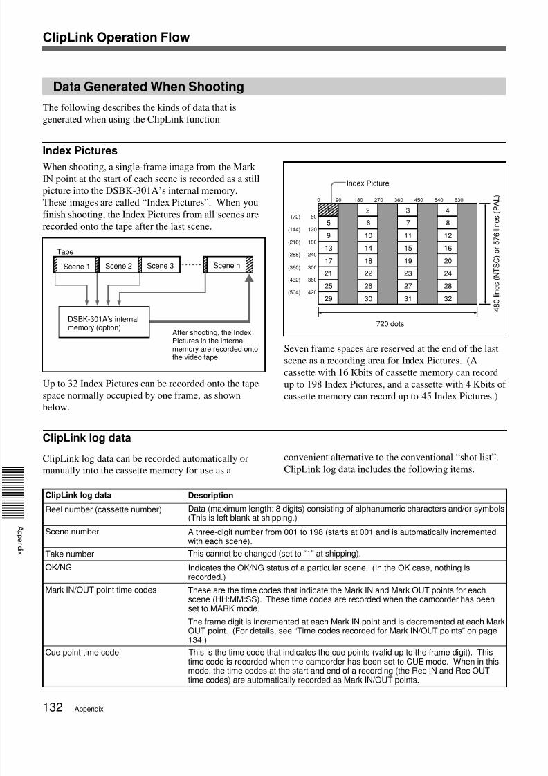
This equipment has been tested and found to comply with
the limits for a Class A digital device, pursuant to Part 15
of the FCC Rules. These limits are designed to providereasonable protection against harmful interference when
the equipment is operated in a commercial environment.
This equipment generates, uses, and can radiate radiofrequency energy and, if not installed and used inaccordance with the instruction manual, may cause
harmful interference to radio communications. Operationof this equipment in a residential area is likely to causeharmful interference in which case the user will be
required to correct the interference at his own expense.
You are cautioned that any changes or modifications notexpressly approved in this manual could void your
authority to operate this equipment.
The shielded interface cable recommended in this manual
must be used with this equipment in order to comply withthe limits for a digital device pursuant to Subpart B of Part15 of FCC Rules.
For the customers in Europe
This product with the CE marking complies with the EMC
Directive (89/336/EEC) issued by the Commission of theEuropean Community.
Compliance with this directive implies conformity to the
following European standards:• EN55103-1: Electromagnetic Interference (Emission)• EN55103-2: Electromagnetic Susceptibility (Immunity)
This product is intended for use in the followingElectromagnetic Environment(s):
E1 (residential), E2 (commercial and light industrial), E3(urban outdoors) and E4 (controlled EMC environment,
ex. TV studio).
7/18/2019 Sony DSR-300A Operation Manual
http://slidepdf.com/reader/full/sony-dsr-300a-operation-manual 3/136Table of Contents 3
Viewing Monochrome Playback in the Viewfinder........... 63
Viewing Color Playback .................................................... 63
Setting Time Values ......................................................... 64Setting the User Bit Value ................................................. 65
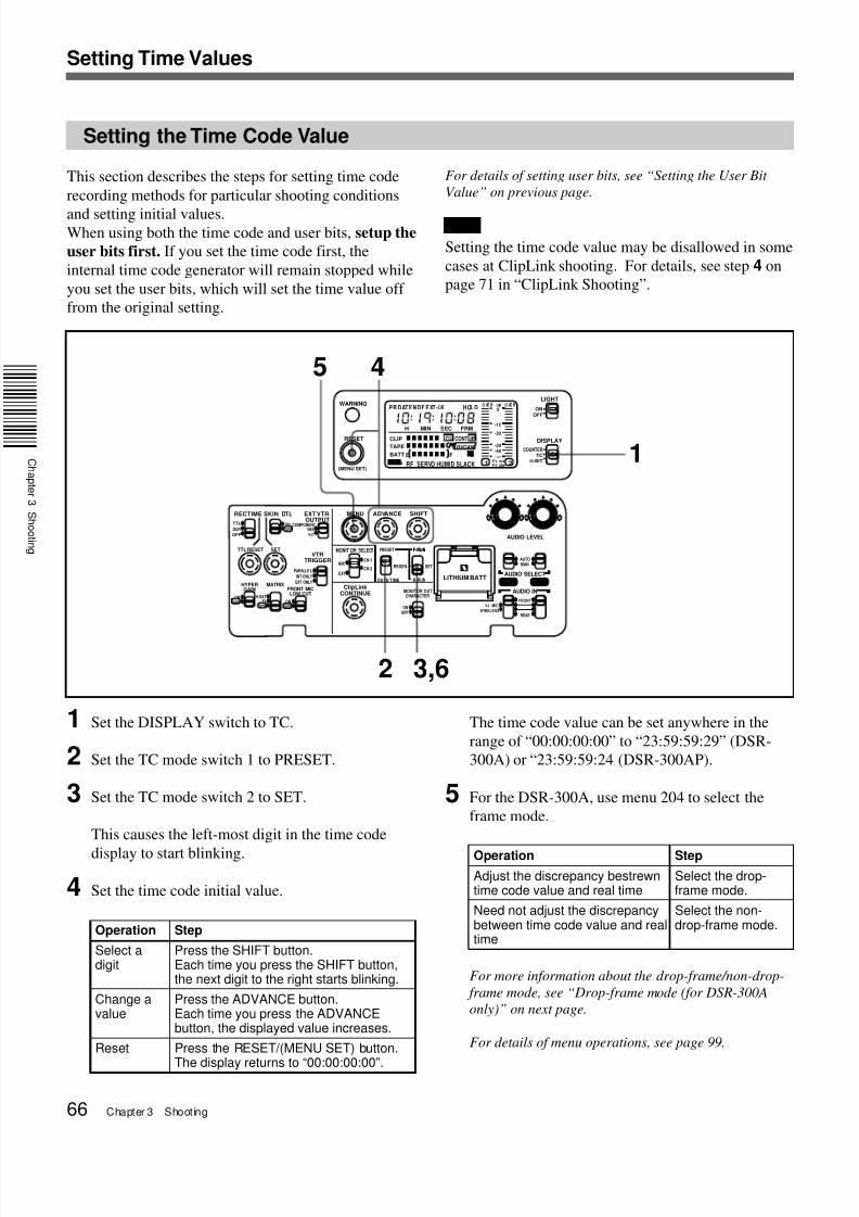
Setting the Time Code Value ............................................. 66
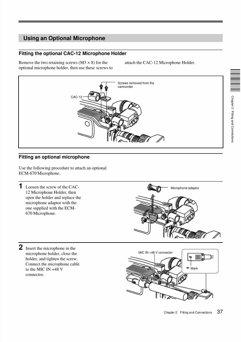
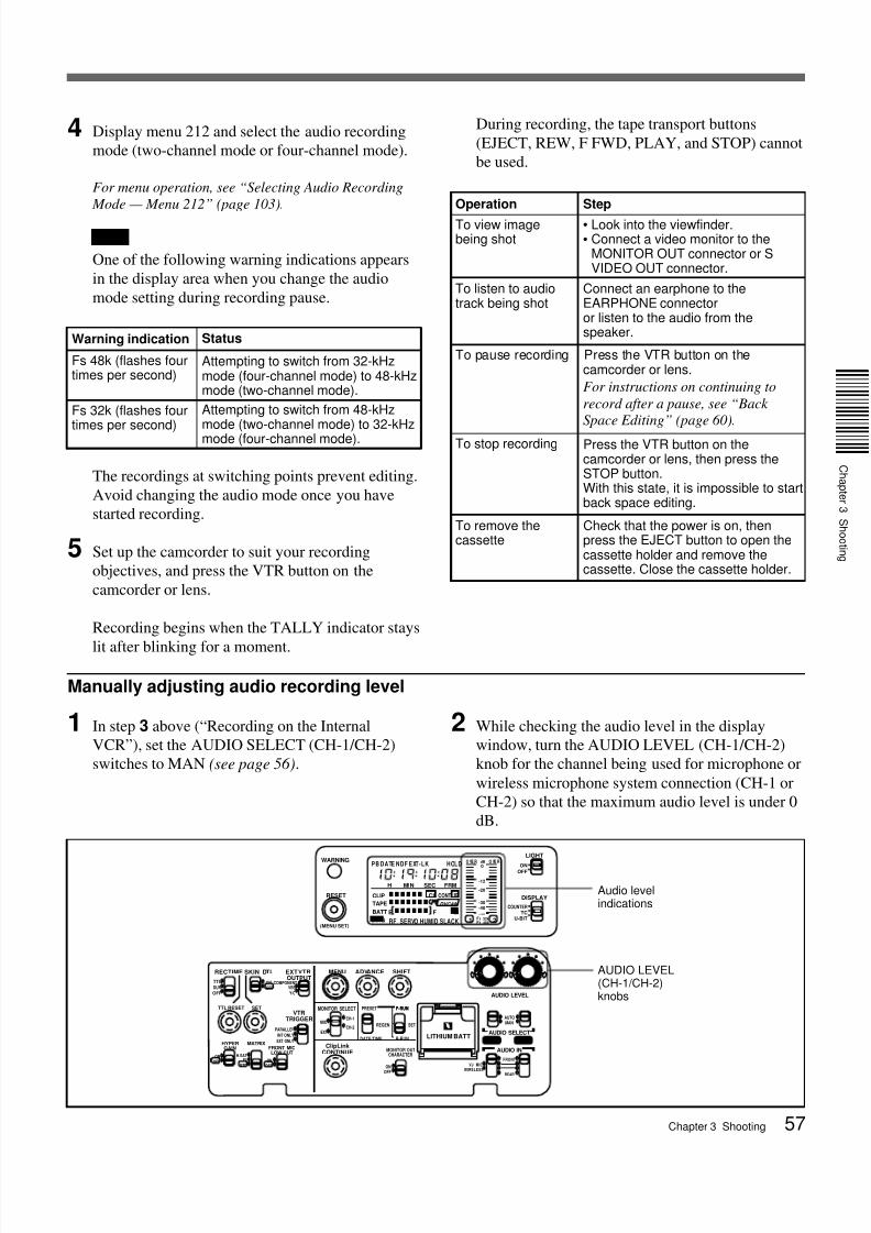
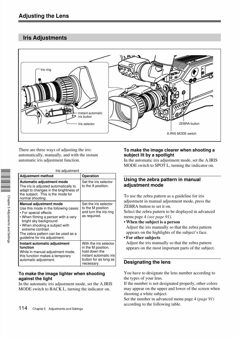
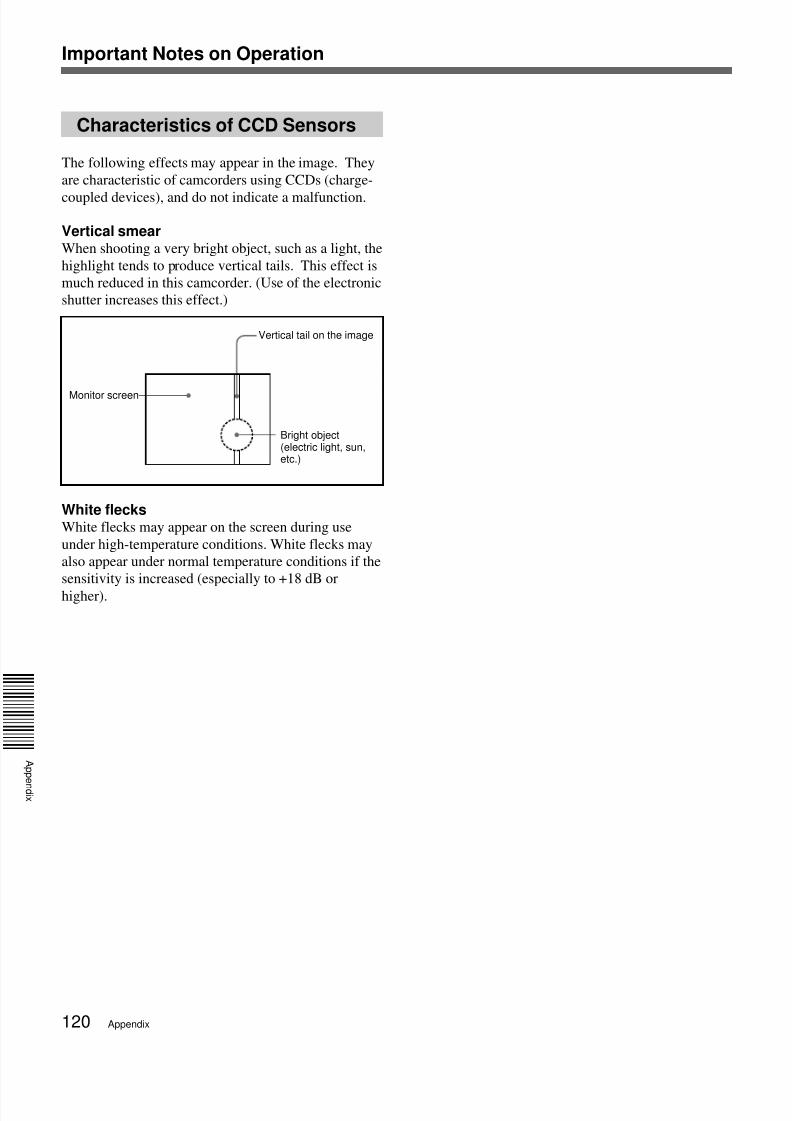
the audio levels being recorded on channels 1 and 2.
The audio levels are indicated in the display window8 .For details, see “8 Display window”.
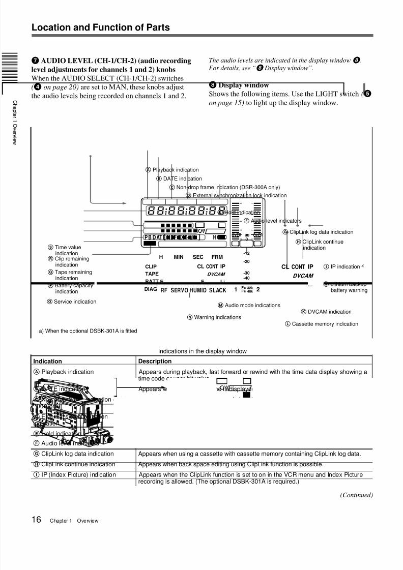
8 Display window
Shows the following items. Use the LIGHT switch (5on page 15) to light up the display window.
∞
H MIN SEC FRM
1
dB
2
PB DATE NDF EXT-LK HOLD
CLIP
TAPE
BATT
DIAG
E F
RF SERVO HUMID SLACK
Li -
-40-30
-12
0
IPCL CONT
OVER OVER
-20
DVCAM
F8 32kF8 48k
Li
IPCL CONT
DVCAM
A Playback indication
Indication Description
A Playback indication Appears during playback, fast forward or rewind with the time data display showing atime code or user bit value.
B DATE indication Appears when the date or time is displayed in the time value indication areaS.
C Non drop-frame indication (DSR-300A only)
Appears when non-drop frame mode is selected.
D External synchronizationindication
Appears when the internal time code generator is locked to an external signal input tothe TC IN connector (3 on page 24).
E Hold indication Appears when the internal time code generator is stopped.
F Audio level indicators These show the audio recording or playback levels of channel 1 and channel 2.
G ClipLink log data indication
H ClipLink continue indication
Appears when using a cassette with cassette memory containing ClipLink log data.
Appears when back space editing using ClipLink function is possible.
I IP (Index Picture) indication Appears when the ClipLink function is set to on in the VCR menu and Index Picturerecording is allowed. (The optional DSBK-301A is required.)
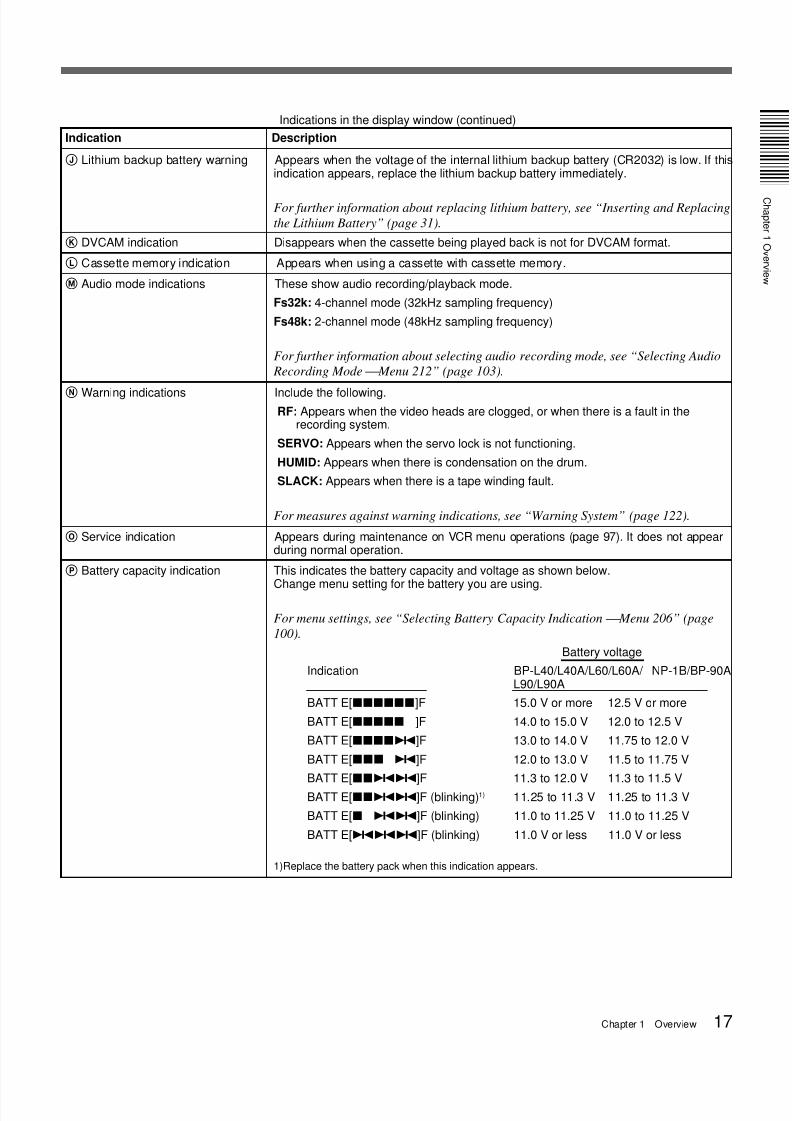
BATT E[xxpp]F (blinking)1) 11.25 to 11.3 V 11.25 to 11.3 V
BATT E[x pp]F (blinking) 11.0 to 11.25 V 11.0 to 11.25 V
BATT E[ppp]F (blinking) 11.0 V or less 11.0 V or less
1)Replace the battery pack when this indication appears.
J Lithium backup battery warning Appears when the voltage of the internal lithium backup battery (CR2032) is low. If thisindication appears, replace the lithium backup battery immediately.
For further information about replacing lithium battery, see “Inserting and Replacing
the Lithium Battery” (page 31).
K DVCAM indication Disappears when the cassette being played back is not for DVCAM format.
L Cassette memory indication Appears when using a cassette with cassette memory.
M Audio mode indications These show audio recording/playback mode.
Fs32k: 4-channel mode (32kHz sampling frequency)
Fs48k: 2-channel mode (48kHz sampling frequency)
For further information about selecting audio recording mode, see “Selecting Audio
Recording Mode Menu 212” (page 103).
N Warning indications Include the following.RF: Appears when the video heads are clogged, or when there is a fault in the
recording system.
SERVO: Appears when the servo lock is not functioning.
HUMID: Appears when there is condensation on the drum.
SLACK: Appears when there is a tape winding fault.
For measures against warning indications, see “Warning System” (page 122).
O Service indication Appears during maintenance on VCR menu operations (page 97). It does not appearduring normal operation.
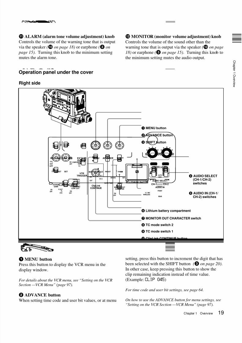
Resets the time value shown in the display window.
This button operates differently depending on settings
of the DISPLAY switch (6
on page 15) and the TCmode switch 1 (9 on page 20) and 2 (8 on page 20).
Also, this button is used to change menu settings.
For details on the VCR menu, see “Setting on the VCR
Section VCR Menu” (page 97).
0 Speaker
Outputs the recorded or playback audio. When a
warning indicator appears in the viewfinder or display
window, the speaker sounds a warning tone.
The speaker is muted (does not output a warning tone)
when an earphone is connected to the EARPHONE
connector (3 on page 15).
For details on the warning tone, see “Warning System”
(page 122).
Switch setting RESET button operation
DISPLAY: COUNTER Resets counter value to0:00:00.
DISPLAY: TCTC mode switch 1: PRESETTC mode switch 2: SET
Resets time code to00:00:00:00.
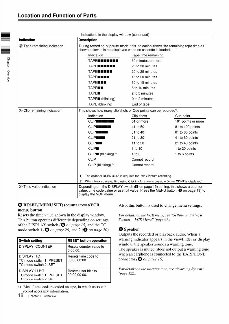
Indications in the display window (continued)
Q Tape remaining indication During recording or pause mode, this indication shows the remaining tape time asshown below. It is not displayed when no cassette is loaded.
Indication Tape time remainingTAPExxxxxxx 30 minutes or more
TAPExxxxxx 25 to 30 minutes
TAPExxxxx 20 to 25 minutes
TAPExxxx 15 to 20 minutes
TAPExxx 10 to 15 minutes
TAPExx 5 to 10 minutes
TAPEx 2 to 5 minutes
TAPEx (blinking) 0 to 2 minutes
TAPE (blinking) End of tape
R Clip remaining indication This shows how many clip shots or Cue points can be recorded1).
Indication Clip shots Cue point
CLIPxxxxxx 51 or more 101 points or more
CLIPxxxxx 41 to 50 81 to 100 points
CLIPxxxx 31 to 40 61 to 80 points
CLIPxxx 21 to 30 41 to 60 points
CLIPxx 11 to 20 21 to 40 points
CLIPx 1 to 10 1 to 20 points
CLIPx (blinking) 2) 1 to 3 1 to 6 points
CLIP Cannot record
CLIP (blinking) 2) Cannot record
1) The optional DSBK-301A is required for Index Picture recording.
2) When back space editing using ClipLink function is possible (when CONT is displayed)
S Time value indication Depending on the DISPLAY switch (6 on page 15) setting, this shows a countervalue, time code value or user bit value. Press the MENU button (1 on page 19) todisplay the VCR menu.
Indication Description
DISPLAY: U-BIT
TC mode switch 1: PRESETTC mode switch 2: SET
Resets user bit a) to00 00 00 00.
a) Bits of time code recorded on tape, in which users can
3 Check the switch settings on the camcorder. (See
pages 12 to 26).
If there is not sufficient time to check the
camcorder settings, you can use “EZ mode” by
setting the EZ MODE button ON. The camcorder
is automatically adjusted to standard settings, and
the iris and the white balance are adjusted
automatically. (See page 106.)
4 Check the settings in the basic menu (page 83) and
advanced menu (page 88).
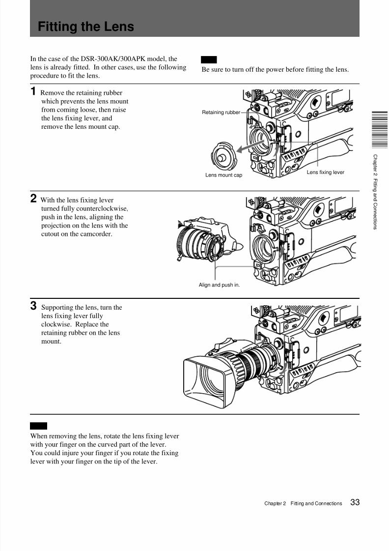
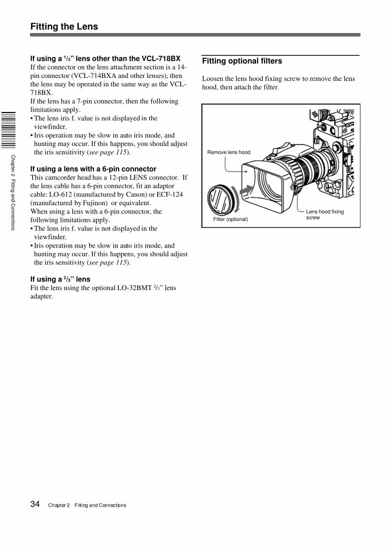
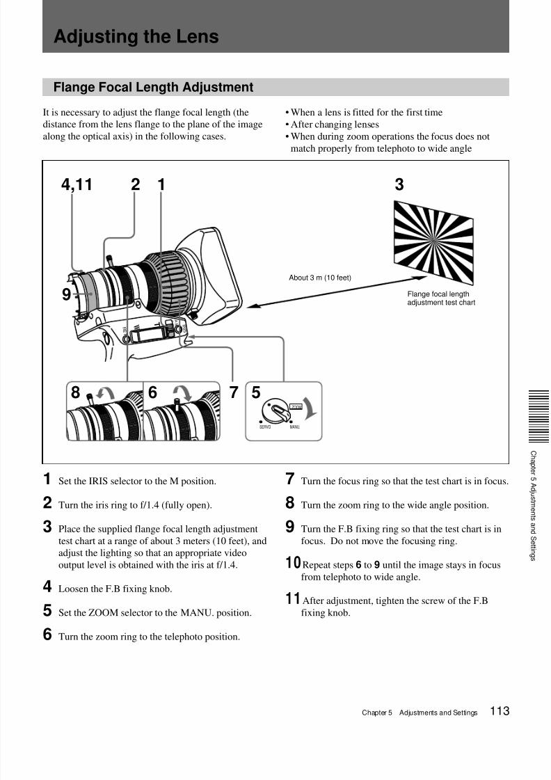
5 Check the lens settings (pages 33 and 34) and
flange focal length adjustment (page 113).
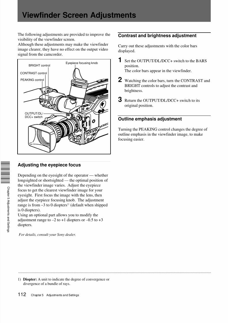
6 Adjust the eyepiece focus, and the contrast and
brightness of the viewfinder image (page 112).
7 Check the sound system settings.
• Microphone connections
• Settings on the VCR section
8 If required, switch on the center marker and/or
safety zone (basic menu page 5 and advanced
menu page 4) and zebra pattern (ZEBRA button) inthe viewfinder image.
9 Adjust the white balance (page 106) and black
balance (page 109).
10Turn the focusing ring so that the subject is
sharply in focus. It may be convenient to use the
Basic Procedure for Shooting
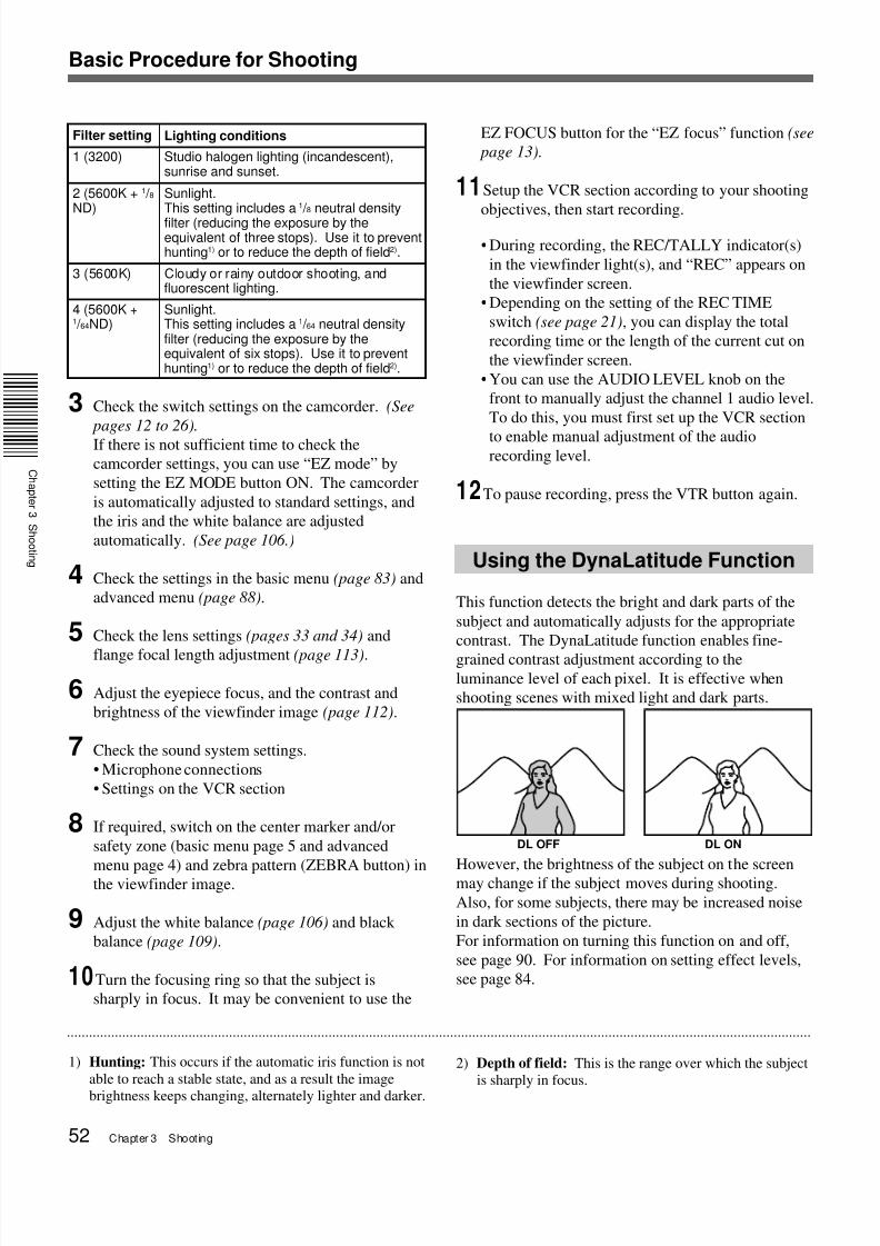
Filter setting Lighting conditions
Studio halogen lighting (incandescent),sunrise and sunset.
2 (5600K + 1 / 8ND)
Sunlight.This setting includes a 1 / 8 neutral densityfilter (reducing the exposure by theequivalent of three stops). Use it to preventhunting1) or to reduce the depth of field2).
3 (5600K) Cloudy or rainy outdoor shooting, andfluorescent lighting.
4 (5600K +1 / 64ND)
Sunlight.This setting includes a 1 / 64 neutral densityfilter (reducing the exposure by theequivalent of six stops). Use it to preventhunting1) or to reduce the depth of field2).
1 (3200)
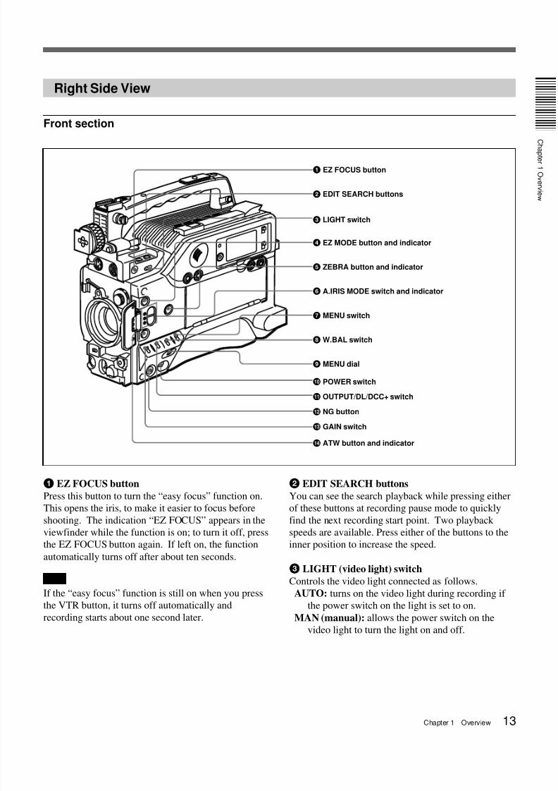
EZ FOCUS button for the “EZ focus” function (see
page 13).
11Setup the VCR section according to your shooting
objectives, then start recording.
• During recording, the REC/TALLY indicator(s)
in the viewfinder light(s), and “REC” appears on
the viewfinder screen.
• Depending on the setting of the REC TIME
switch (see page 21), you can display the total
recording time or the length of the current cut on
the viewfinder screen.
• You can use the AUDIO LEVEL knob on the
front to manually adjust the channel 1 audio level.
To do this, you must first set up the VCR section
to enable manual adjustment of the audiorecording level.
12To pause recording, press the VTR button again.
Using the DynaLatitude Function
This function detects the bright and dark parts of the
subject and automatically adjusts for the appropriate
contrast. The DynaLatitude function enables fine-
grained contrast adjustment according to theluminance level of each pixel. It is effective when
shooting scenes with mixed light and dark parts.
However, the brightness of the subject on the screen
may change if the subject moves during shooting.
Also, for some subjects, there may be increased noise
in dark sections of the picture.
For information on turning this function on and off,
see page 90. For information on setting effect levels,
see page 84.
1) Hunting: This occurs if the automatic iris function is not
able to reach a stable state, and as a result the image
brightness keeps changing, alternately lighter and darker.
2) Depth of field: This is the range over which the subject
How is the battery? BATT E [xxxxxx] F: The battery is fully charged.If two or fewer marks appear and the indication is blinking,replace the battery.
“8 Display window” (page 16)
Make sure that the Li is not shown in the display window.
If it is shown, replace the lithium battery.“Inserting and Replacing theLithium Battery” (page 31)
Is there a condensationproblem?
“Condensation” (page 123)
Has the lithium batterybeen inserted and is itcharged?
Make sure that the “HUMID” indication is not shown in thedisplay window. If it is shown, do not use the equipment untilthe “HUMID” indication disappears.
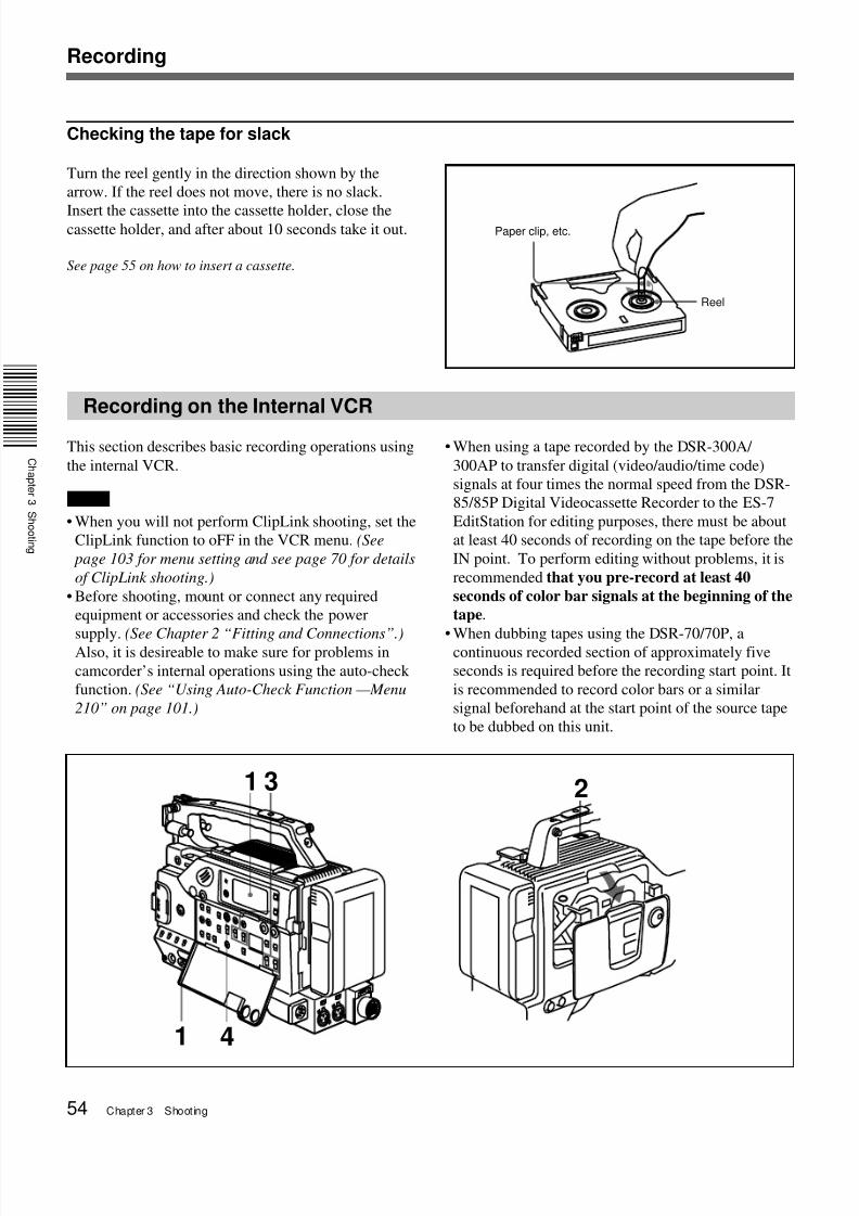
(Continued)
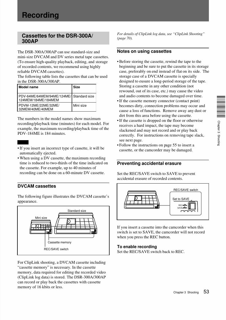
2 Press the EJECT button to open the cassette
holder, and insert the cassette.
Make sure that the cassette’s REC/SAVE switch is
set to REC, then check for tape slack before
loading the cassette.
For details on handling cassettes, see “Cassettes for the
DSR-300A/300AP” on page 53.
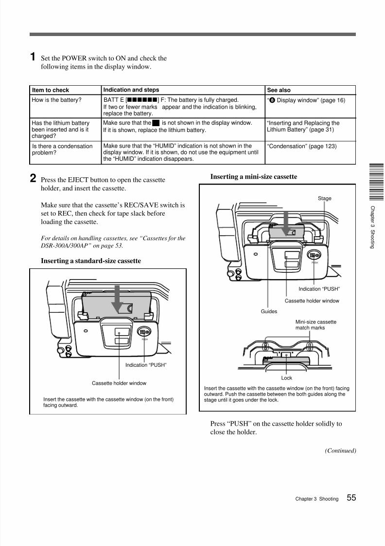
Inserting a standard-size cassette
PUSH
Indication “PUSH”
Cassette holder window
Insert the cassette with the cassette window (on the front)facing outward.
PUSH
Inserting a mini-size cassette
Press “PUSH” on the cassette holder solidly to
close the holder.
Insert the cassette with the cassette window (on the front) facingoutward. Push the cassette between the both guides along thestage until it goes under the lock.
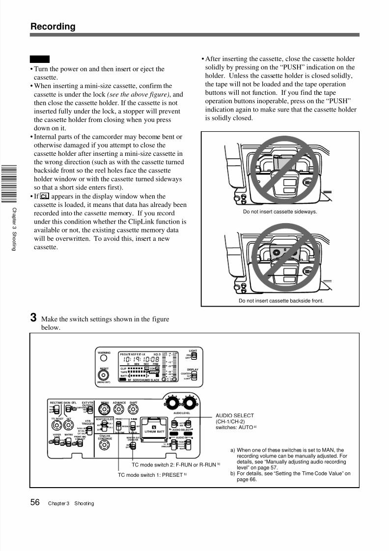
• After inserting the cassette, close the cassette holder
solidly by pressing on the “PUSH” indication on the
holder. Unless the cassette holder is closed solidly,
the tape will not be loaded and the tape operation
buttons will not function. If you find the tape
operation buttons inoperable, press on the “PUSH”
indication again to make sure that the cassette holder
is solidly closed.
Do not insert cassette backside front.
Do not insert cassette sideways.
TC mode switch 2: F-RUN or R-RUN b)
TC mode switch 1: PRESET b)
AUDIO SELECT(CH-1/CH-2)switches: AUTO a)
a) When one of these switches is set to MAN, therecording volume can be manually adjusted. Fordetails, see “Manually adjusting audio recordinglevel” on page 57.
b) For details, see “Setting the Time Code Value” onpage 66.
Notes
• Turn the power on and then insert or eject the
cassette.
• When inserting a mini-size cassette, confirm the
cassette is under the lock (see the above figure), andthen close the cassette holder. If the cassette is not
inserted fully under the lock, a stopper will prevent
the cassette holder from closing when you press
down on it.
• Internal parts of the camcorder may become bent or
otherwise damaged if you attempt to close the
cassette holder after inserting a mini-size cassette in
the wrong direction (such as with the cassette turned
backside front so the reel holes face the cassette
holder window or with the cassette turned sideways
so that a short side enters first).
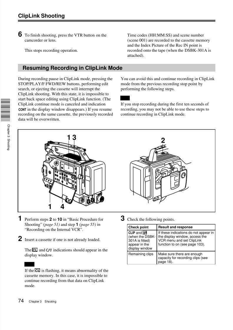
• If CL appears in the display window when the
cassette is loaded, it means that data has already been
recorded into the cassette memory. If you record
under this condition whether the ClipLink function is
available or not, the existing cassette memory data
For menu operation, see “Selecting Audio Recording
Mode — Menu 212” (page 103).
Note
One of the following warning indications appears
in the display area when you change the audio
mode setting during recording pause.
The recordings at switching points prevent editing.
Avoid changing the audio mode once you have
started recording.
5 Set up the camcorder to suit your recording
objectives, and press the VTR button on the
camcorder or lens.
Recording begins when the TALLY indicator stays
lit after blinking for a moment.
During recording, the tape transport buttons
(EJECT, REW, F FWD, PLAY, and STOP) cannot
be used.
Warning indication Status
Fs 48k (flashes fourtimes per second)
Attempting to switch from 32-kHzmode (four-channel mode) to 48-kHzmode (two-channel mode).
Fs 32k (flashes four
times per second)
Attempting to switch from 48-kHzmode (two-channel mode) to 32-kHzmode (four-channel mode).
Operation Step
To view imagebeing shot
• Look into the viewfinder.• Connect a video monitor to the
MONITOR OUT connector or SVIDEO OUT connector.
To listen to audiotrack being shot
Connect an earphone to theEARPHONE connectoror listen to the audio from thespeaker.
To pause recording Press the VTR button on thecamcorder or lens.
For instructions on continuing to
record after a pause, see “Back
Space Editing” (page 60).
To stop recording Press the VTR button on thecamcorder or lens, then press theSTOP button.With this state, it is impossible to startback space editing.
To remove thecassette
Check that the power is on, thenpress the EJECT button to open thecassette holder and remove thecassette. Close the cassette holder.
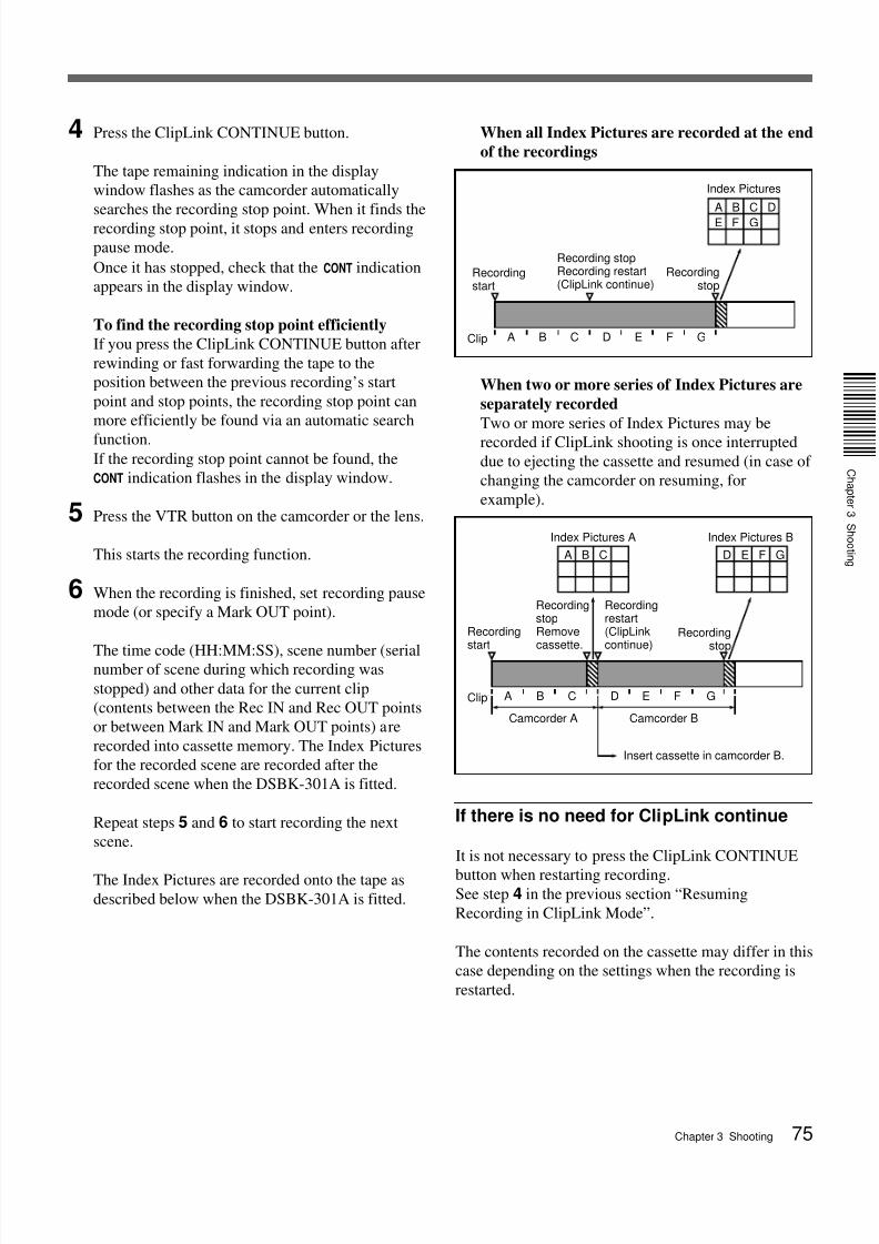
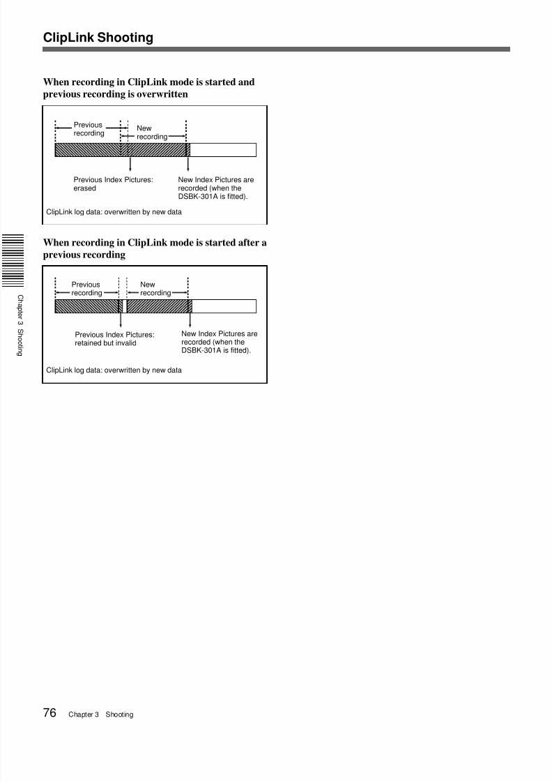
When recording in ClipLink mode is started after a
previous recording
Previous
recording
New
recording
Previous Index Pictures:erased
New Index Pictures arerecorded (when theDSBK-301A is fitted).
ClipLink log data: overwritten by new data
Previous Index Pictures:retained but invalid
New Index Pictures arerecorded (when theDSBK-301A is fitted).
Newrecording
Previousrecording
ClipLink log data: overwritten by new data
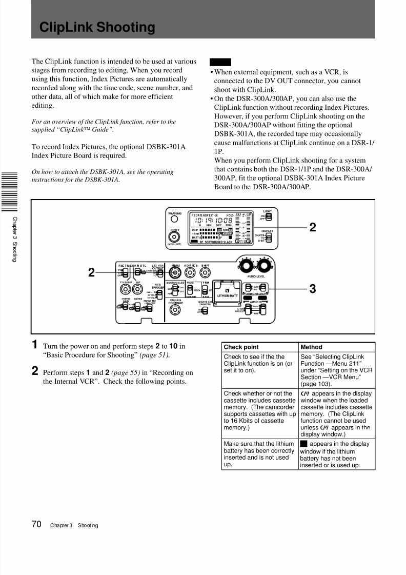
ClipLink Shooting
7/18/2019 Sony DSR-300A Operation Manual
http://slidepdf.com/reader/full/sony-dsr-300a-operation-manual 77/136Chapter 4 Viewfinder Screen Indications and Menus 77
O N
O F F
M E N U
S T A T U S
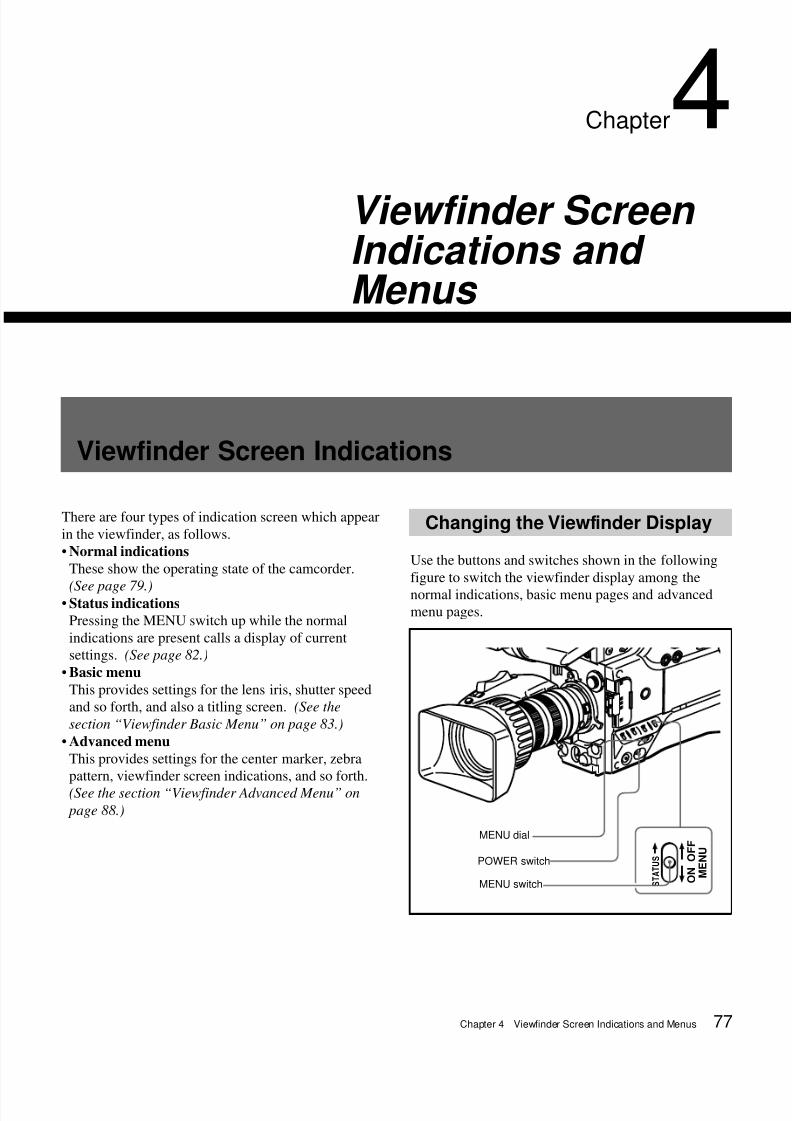
Viewfinder Screen Indications
There are four types of indication screen which appear
in the viewfinder, as follows.
• Normal indications
These show the operating state of the camcorder.
(See page 79.)• Status indications
Pressing the MENU switch up while the normal
indications are present calls a display of current
settings. (See page 82.)
• Basic menu
This provides settings for the lens iris, shutter speed
and so forth, and also a titling screen. (See the
section “Viewfinder Basic Menu” on page 83.)
• Advanced menu
This provides settings for the center marker, zebra
pattern, viewfinder screen indications, and so forth.
(See the section “Viewfinder Advanced Menu” on
page 88.)
Chapter4Viewfinder Screen Indications and Menus
MENU dial
POWER switch
MENU switch
Changing the Viewfinder Display
Use the buttons and switches shown in the following
figure to switch the viewfinder display among the
normal indications, basic menu pages and advanced
menu pages.
7/18/2019 Sony DSR-300A Operation Manual
http://slidepdf.com/reader/full/sony-dsr-300a-operation-manual 78/13678 Chapter 4 Viewfinder Screen Indications and Menus
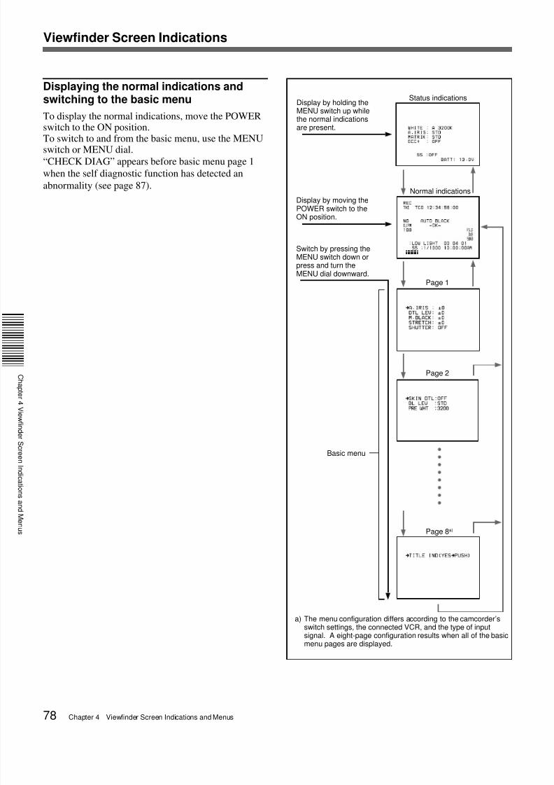
Display by moving thePOWER switch to theON position.
Switch by pressing theMENU switch down orpress and turn the
MENU dial downward.
Display by holding theMENU switch up whilethe normal indicationsare present.
Status indications
Normal indications
Page 1
Page 2
Basic menu
a) The menu configuration differs according to the camcorder’sswitch settings, the connected VCR, and the type of inputsignal. A eight-page configuration results when all of the basicmenu pages are displayed.
Page 8a)
Displaying the normal indications andswitching to the basic menu
To display the normal indications, move the POWERswitch to the ON position.
To switch to and from the basic menu, use the MENUswitch or MENU dial.
“CHECK DIAG” appears before basic menu page 1
when the self diagnostic function has detected an
abnormality (see page 87).
Viewfinder Screen Indications
7/18/2019 Sony DSR-300A Operation Manual
http://slidepdf.com/reader/full/sony-dsr-300a-operation-manual 79/136Chapter 4 Viewfinder Screen Indications and Menus 79
C
a p t e
e
d e
S c e e
d c a t o
s a
d
e
u s
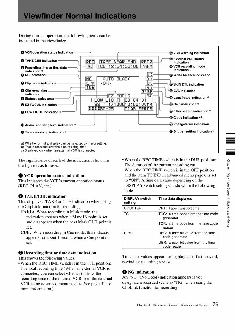
During normal operation, the following items can be
indicated in the viewfinder.
1 VCR operation status indication qs VCR warning indication
DISPLAY switchsetting
Time data displayed
COUNTER CNT: Tape transport time
TC TCG: a time code from the time codegenerator
TCR: a time code from the time codereader
U-BIT UBG: a user bit value from the timecode generator
UBR: a user bit value from the timecode reader
2 TAKE/CUE indication
3 Recording time or time dataindication a)
4 NG indication
5 Clip mode indication
6 Clip remainingindication
7 Status display area
8 EZ FOCUS indication
9 LOW LIGHT indication a)
q; Audio recording level indicators a)
qa Tape remaining indication a)
qd External VCR statusindication c)
qf VCR recording modeindication c)
qg White balance indication
qh SKIN DTL indication
qj EVS indication
qk Lens f-stop indication a)
ql Gain indication a)
w; Filter setting indication a)
wa Clock indication a), b)
ws Voltage/error indication
wd Shutter setting indication a)
a) Whether or not to display can be selected by menu setting.b) This is recorded over the picture being shot.c) Displayed only when an external VCR is connected
Viewfinder Normal Indications
The significance of each of the indications shown in
the figure is as follows.
1 VCR operation status indicationThis indicates the VCR’s current operation status
(REC, PLAY, etc.).
2 TAKE/CUE indication
This displays a TAKE or CUE indication when using
the ClipLink function for recording.
TAKE: When recording in Mark mode, this
indication appears when a Mark IN point is set
and disappears when the next Mark OUT point is
set.
CUE: When recording in Cue mode, this indicationappears for about 1 second when a Cue point is
set.
3 Recording time or time data indication
This shows the following values.
• When the REC TIME switch is in the TTL position:
The total recording time (When an external VCR is
connected, you can select whether to show the
recording time of the internal VCR or of the external
VCR using advanced menu page 4. See page 91 for
more information.)
• When the REC TIME switch is in the DUR position:
The duration of the current recording cut
• When the REC TIME switch is in the OFF position
and the item TC IND in advanced menu page 6 is setto “ON”: A time data value depending on the
DISPLAY switch settings as shown in the following
table
Time data values appear during playback, fast forward,
http://slidepdf.com/reader/full/sony-dsr-300a-operation-manual 81/136Chapter 4 Viewfinder Screen Indications and Menus 81
C
a p t e
e
d e
S c e e
d c a t o
s a
d
e
u s
Note
If the message appears other than above, contact your
Sony dealer.
qd External VCR status indication (when an
external VCR is connected)
Shows the external VCR operation status.
qf VCR recording mode indication (when an
external VCR is connected)
Shows recording mode of the internal and external
VCRs set by the VTR TRIGGER switch.
qgWhite balance indication
The following indications appear.
qh SKIN DTL indication
This appears when the skin detail function is activated
(The SKIN DTL switch is set ON.)
qj EVS indication
This appears when the EVS (Enhanced Vertical
definition System) function is enabled. (See page
110.)
qk Lens f-stop indication
This shows the f-stop of the lens.
Notes
• Depending on the lens being used, this indication
may differ slightly from the actual f-stop on the lens.
• No indications appear when you use a lens with the
7-pin lens connector.
ql Gain indication
This shows the gain value, and the settings of the
HYPER GAIN switch and the DPR (Dual Pixel
Readout) function (see page 90) as shown in the
following table.
w; Filter setting indication
This shows the setting of the FILTER control.
wa Clock indication
The clock indication is shown in one of the following
ways (according to the CLOCK IND setting of CAM,
BARS, or OFF in advanced menu page 8).
CAM: Always displayed.
BARS: Displayed whenever color bars are
displayed.
OFF: Not displayed.
If the clock indication is displayed during recording, it
is recorded onto the image.
Indication Filter setting
3200 1 (3200K)
56ND 2 (5600K + 1 / 8ND)
5600 3 (5600K)
56ND 4 (5600K + 1 / 64ND)
Example indication Meaning
18 dB Gain setting is 18 dB.
DPR 18 dB The DPR function is enabled.In this case the DPR functionapproximately doubles the gain (anincrease of 6 dB) over the currentgain setting (in this case 18 dB).
HYPER The HYPER GAIN switch is in theON position.In this case the hyper gain functionincreases the gain by a factor ofabout 60 with respect to 0 dBregardless of the current gainsetting (that is, increased to 36 dB).
Indication Meaning
PARA Simultaneous recording of the internaland external VCRs
INT Recording on the internal VCR
EXT Recording on the external VCR
Indication Meaning
EZ Operating in EZ mode (The ATW function isselected.)
ATW The ATW function is selected. (The ATWbutton was pressed and the indicator is lit.)
W:A White balance memory A is selected.W:B White balance memory B is selected.
W:P Preset white balance is selected.
W:M Manual adjustment is performed remotely.
Indication Meaning
CLIP CONT? Asking whether you will continueshooting in ClipLink mode or not whenthe cassette contains ClipLink data.(The indication disappears when you
press the ClipLink CONTINUE buttonor start the next shooting withoutpressing it.)
CLIP END
At ClipLink shooting, capacity for only1 to 3 clips remains.
CLIP NEAR END
Impossible to record any more clipshots.
7/18/2019 Sony DSR-300A Operation Manual
http://slidepdf.com/reader/full/sony-dsr-300a-operation-manual 82/13682 Chapter 4 Viewfinder Screen Indications and Menus
ws Voltage/error indication
The current voltage is displayed whenever the power
supply voltage dips below 11.3 V DC. However, you
can also display the current voltage at any time by
pressing and holding the MENU switch in the upward
position (the display is shown for as long as you hold
the switch upward).
An error message is displayed when an abnormality
has been detected by the auto diagnostic function
(page 87). If there is a voltage drop below 11.3 V DC
and an error has been detected, the low voltage
indication alternates at one-second intervals with the
error indication.
If an error message appears, contact your Sony dealer.
If using an Anton Bauer Intelligent Battery SystemThe remaining battery capacity is shown as a
percentage.
wd Shutter setting indication
When the SHUTTER switch has been set to ON, the
basic menu page 1 setting for the item SHUTTER
(shutter speed, CLS frequency, EVS) is displayed here.
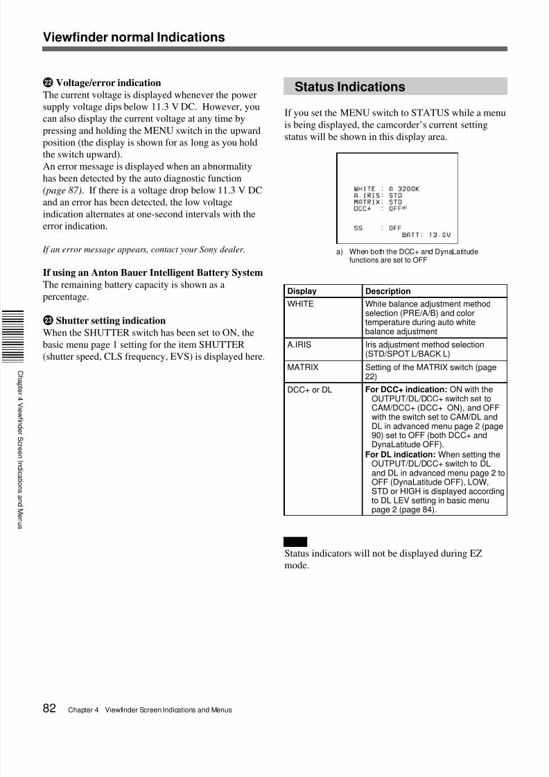
Status Indications
If you set the MENU switch to STATUS while a menu
is being displayed, the camcorder’s current setting
status will be shown in this display area.
a) When both the DCC+ and DynaLatitudefunctions are set to OFF
Display Description
WHITE White balance adjustment methodselection (PRE/A/B) and colortemperature during auto whitebalance adjustment
For DCC+ indication: ON with theOUTPUT/DL/DCC+ switch set to
CAM/DCC+ (DCC+ ON), and OFFwith the switch set to CAM/DL andDL in advanced menu page 2 (page90) set to OFF (both DCC+ andDynaLatitude OFF).
For DL indication: When setting theOUTPUT/DL/DCC+ switch to DLand DL in advanced menu page 2 toOFF (DynaLatitude OFF), LOW,STD or HIGH is displayed accordingto DL LEV setting in basic menupage 2 (page 84).
Viewfinder normal Indications
NoteStatus indicators will not be displayed during EZ
http://slidepdf.com/reader/full/sony-dsr-300a-operation-manual 85/136Chapter 4 Viewfinder Screen Indications and Menus 85
C
a p t e
e
d e
S c e e
d c a t o
s a
d
e
u s
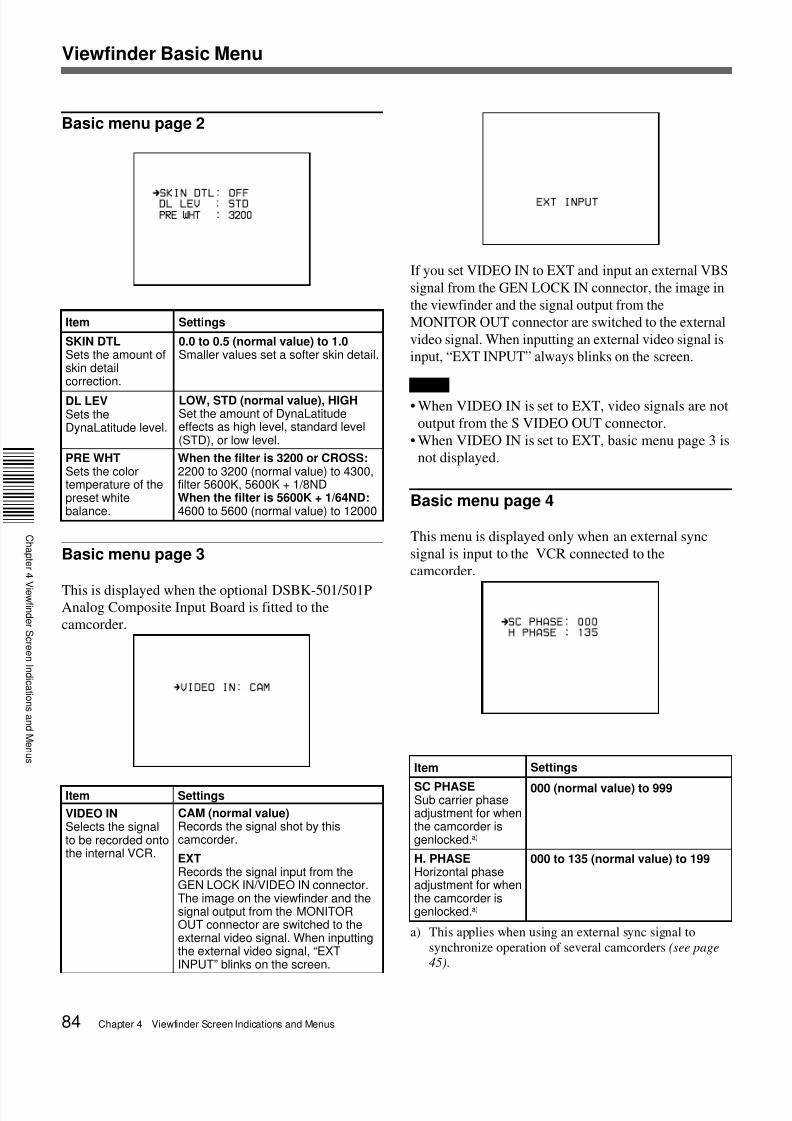
Basic menu page 5
Setting the recording time in secondsMove the cursor to DUR TIME, then press the MENU
dial.
A value of seconds appears.
If you turn the MENU dial when “59” is displayed, the
number under “MM” increased by one.
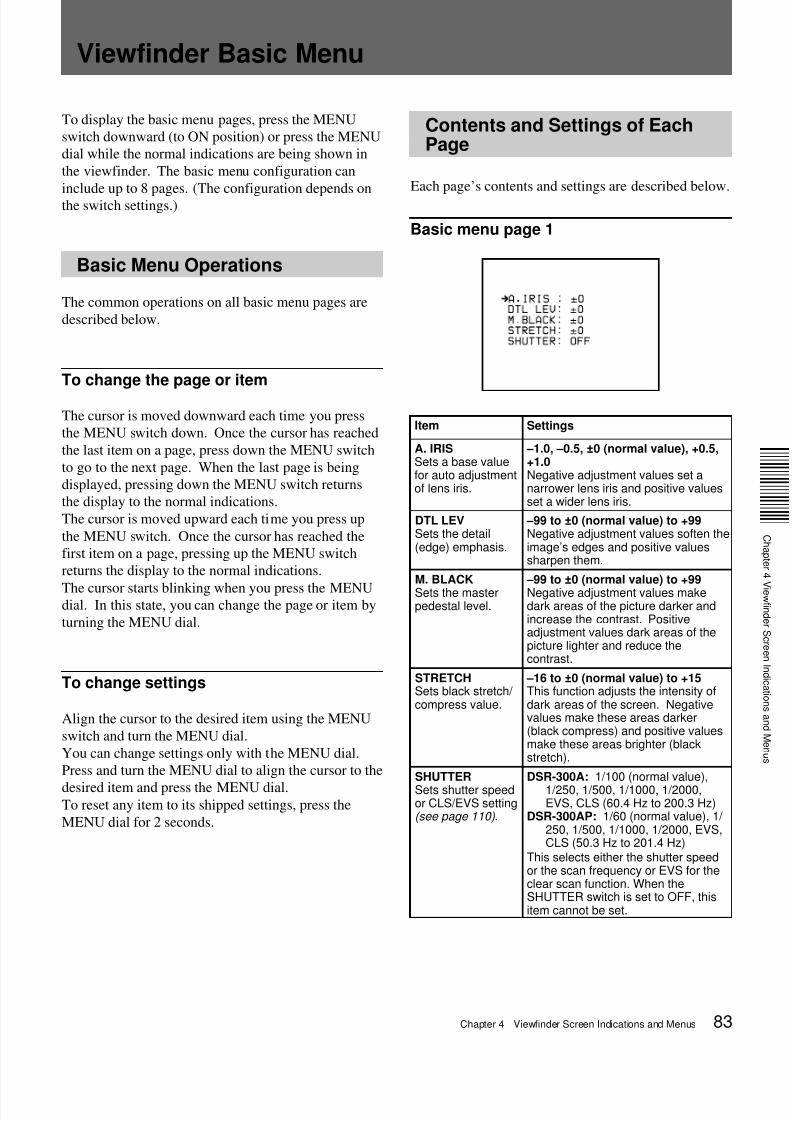
Item Settings
MARKERSets marker display ON/OFF.
ON (normal value), OFFMarkers are displayedwhen this setting is ONand is not displayed
when it is OFF.When the setting is ON,go to advanced menupage 4 to select the typeof marker (see page 91).
DUR TIMESets the recording timeSetting the recoriding timebefore shooting helps you withmaking scenes of equalduration.When shooting with displayingthe recording time of the currentcut in the viewfinder (with theREC TIME switch set to DUR),
the recording time indicationflashes to remind you that therecording time has passed.
00:00 to 59:59 (minuteto second)See “Setting therecording time inseconds”.
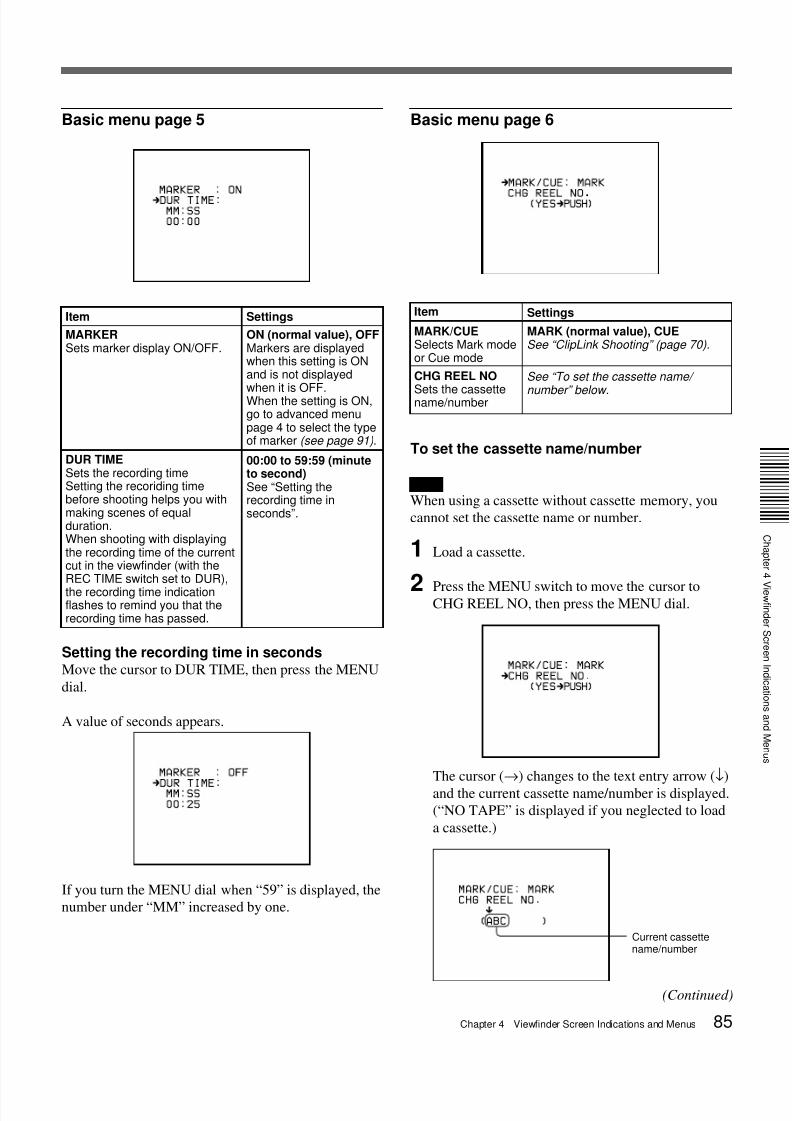
Basic menu page 6
To set the cassette name/number
Note
When using a cassette without cassette memory, you
cannot set the cassette name or number.
1 Load a cassette.
2 Press the MENU switch to move the cursor toCHG REEL NO, then press the MENU dial.
The cursor (→) changes to the text entry arrow (↓)
and the current cassette name/number is displayed.
(“NO TAPE” is displayed if you neglected to load
a cassette.)
Item Settings
MARK/CUESelects Mark modeor Cue mode
MARK (normal value), CUESee “ClipLink Shooting” (page 70).
CHG REEL NO
Sets the cassettename/number
See “To set the cassette name/
number” below.
Current cassettename/number
(Continued)
7/18/2019 Sony DSR-300A Operation Manual
http://slidepdf.com/reader/full/sony-dsr-300a-operation-manual 86/13686 Chapter 4 Viewfinder Screen Indications and Menus
Viewfinder Basic Menu
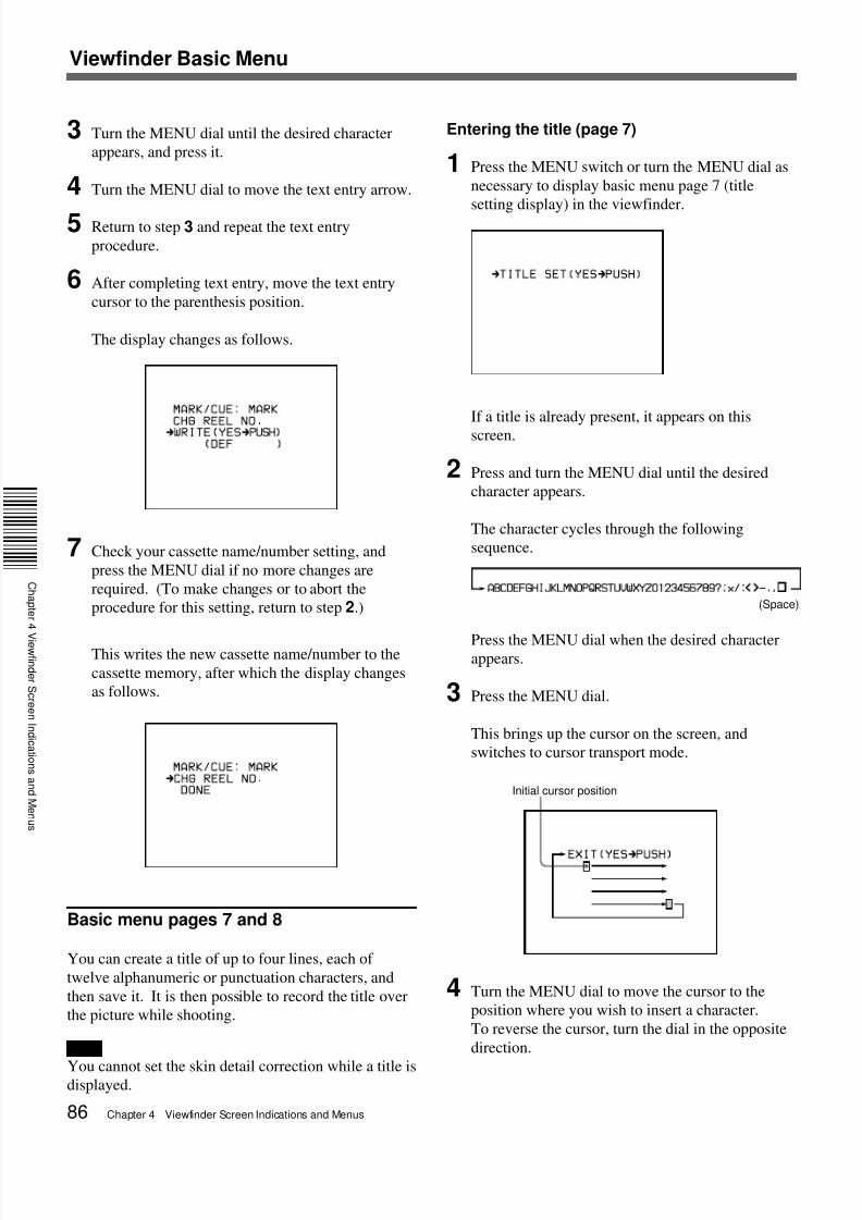
3 Turn the MENU dial until the desired character
appears, and press it.
4 Turn the MENU dial to move the text entry arrow.
5 Return to step 3 and repeat the text entry
procedure.
6 After completing text entry, move the text entry
cursor to the parenthesis position.
The display changes as follows.
7 Check your cassette name/number setting, and
press the MENU dial if no more changes are
required. (To make changes or to abort the
procedure for this setting, return to step 2.)
This writes the new cassette name/number to the
cassette memory, after which the display changes
as follows.
Basic menu pages 7 and 8
You can create a title of up to four lines, each of
twelve alphanumeric or punctuation characters, and
then save it. It is then possible to record the title over
the picture while shooting.
Note
You cannot set the skin detail correction while a title isdisplayed.
Initial cursor position
(Space)
Entering the title (page 7)
1 Press the MENU switch or turn the MENU dial as
necessary to display basic menu page 7 (title
setting display) in the viewfinder.
If a title is already present, it appears on this
screen.
2 Press and turn the MENU dial until the desired
character appears.
The character cycles through the following
sequence.
Press the MENU dial when the desired characterappears.
3 Press the MENU dial.
This brings up the cursor on the screen, and
switches to cursor transport mode.
4 Turn the MENU dial to move the cursor to the
position where you wish to insert a character.
To reverse the cursor, turn the dial in the opposite
direction.
7/18/2019 Sony DSR-300A Operation Manual
http://slidepdf.com/reader/full/sony-dsr-300a-operation-manual 87/136Chapter 4 Viewfinder Screen Indications and Menus 87
C
a p t e
e
d e
S c e e
d c a t o
s a
d
e
u s
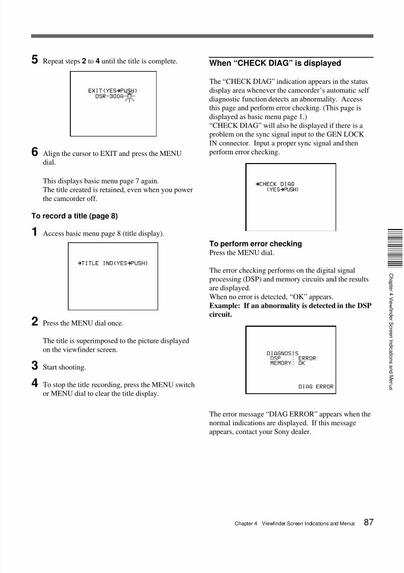
5 Repeat steps 2 to 4 until the title is complete.
6 Align the cursor to EXIT and press the MENU
dial.
This displays basic menu page 7 again.
The title created is retained, even when you power
the camcorder off.
To record a title (page 8)
1 Access basic menu page 8 (title display).
2 Press the MENU dial once.
The title is superimposed to the picture displayed
on the viewfinder screen.
3 Start shooting.
4 To stop the title recording, press the MENU switch
or MENU dial to clear the title display.
When “CHECK DIAG” is displayed
The “CHECK DIAG” indication appears in the status
display area whenever the camcorder’s automatic self
diagnostic function detects an abnormality. Accessthis page and perform error checking. (This page is
displayed as basic menu page 1.)
“CHECK DIAG” will also be displayed if there is a
problem on the sync signal input to the GEN LOCK
IN connector. Input a proper sync signal and then
perform error checking.
To perform error checkingPress the MENU dial.
The error checking performs on the digital signal
processing (DSP) and memory circuits and the results
are displayed.
When no error is detected, “OK” appears.
Example: If an abnormality is detected in the DSP
circuit.
DIAGNOSIS DSP : ERRORMEMORY: OK
DIAG ERROR
The error message “DIAG ERROR” appears when the
normal indications are displayed. If this message
appears, contact your Sony dealer.
7/18/2019 Sony DSR-300A Operation Manual
http://slidepdf.com/reader/full/sony-dsr-300a-operation-manual 88/13688 Chapter 4 Viewfinder Screen Indications and Menus
Viewfinder Advanced Menu
Advanced Menu Operations
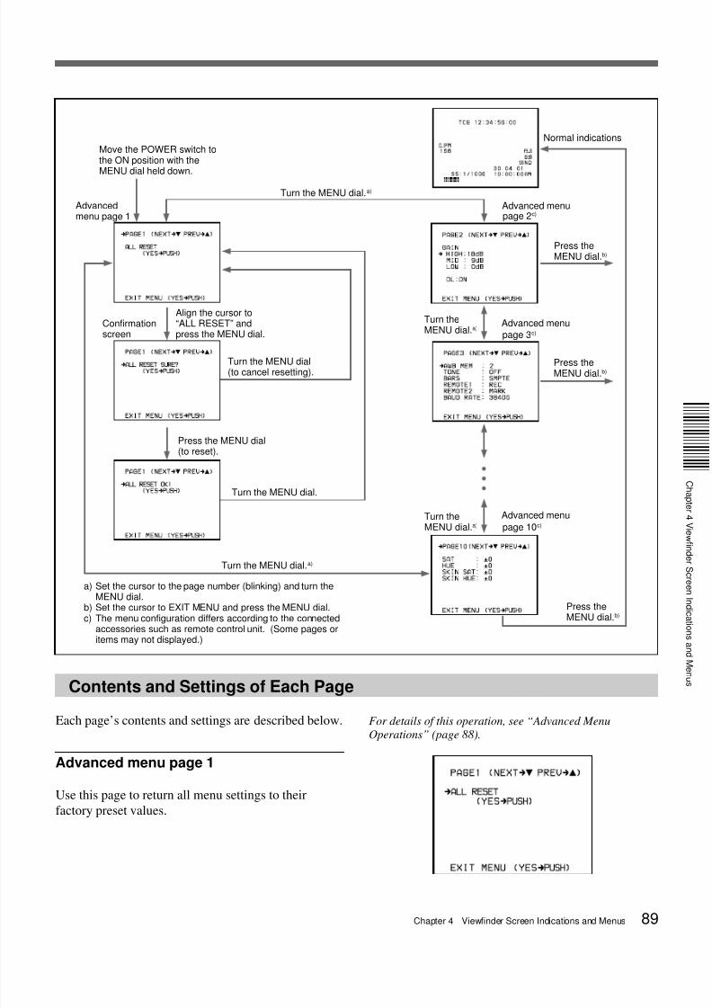
See also the figure on next page.
To display the advanced menu
Move the POWER switch to the ON position while
holding down the MENU dial.
To change the page
Align the cursor to the page number and press the
MENU dial while the page number is blinking. Turn
the dial until the desired page.
To select items in a page
Press the MENU dial to blink the cursor, and press the
MENU switch to move the cursor among the menu
items. While the cursor is blinking, you can move the
cursor by turning the MENU dial.
To change settings
This operation is the same as for the basic menus.
For a description of basic menu operations, see page 83.
To reinitialize all settings in the advancedmenu to their factory defaults1) Align the cursor to ALL RESET and press the
MENU dial. (The indication changes to “ALLRESET SURE?”.)
2) Press the MENU dial again. (The indicationchanges to “ALL RESET OK” and reinitializationcompletes.) To cancel the reinitialization, turn the
MENU dial (without pressing). The indicationreturns to “ALL RESET”.
7/18/2019 Sony DSR-300A Operation Manual
http://slidepdf.com/reader/full/sony-dsr-300a-operation-manual 89/136Chapter 4 Viewfinder Screen Indications and Menus 89
C
a p t e
e
d e
S c e e
d c a t o
s a
d
e
u s
Contents and Settings of Each Page
Each page’s contents and settings are described below.
Advanced menu page 1
Use this page to return all menu settings to their
factory preset values.
For details of this operation, see “Advanced Menu
Operations” (page 88).
a) Set the cursor to the page number (blinking) and turn theMENU dial.
b) Set the cursor to EXIT MENU and press the MENU dial.c) The menu configuration differs according to the connected
accessories such as remote control unit. (Some pages oritems may not displayed.)
Move the POWER switch tothe ON position with theMENU dial held down.
Turn the MENU dial.a)
Align the cursor to“ALL RESET” andpress the MENU dial.
Advancedmenu page 1
Turn the MENU dial(to cancel resetting).
Press the MENU dial(to reset).
Turn the MENU dial.
Turn the MENU dial.a)
Confirmationscreen
Press theMENU dial.b)
Normal indications
page 2c)
Press theMENU dial.b)
page 3c)
Turn theMENU dial.a)
Turn the
MENU dial.a)
page 10c)
Press theMENU dial.b)
Advanced menu
Advanced menu
Advanced menu
7/18/2019 Sony DSR-300A Operation Manual
http://slidepdf.com/reader/full/sony-dsr-300a-operation-manual 90/13690 Chapter 4 Viewfinder Screen Indications and Menus
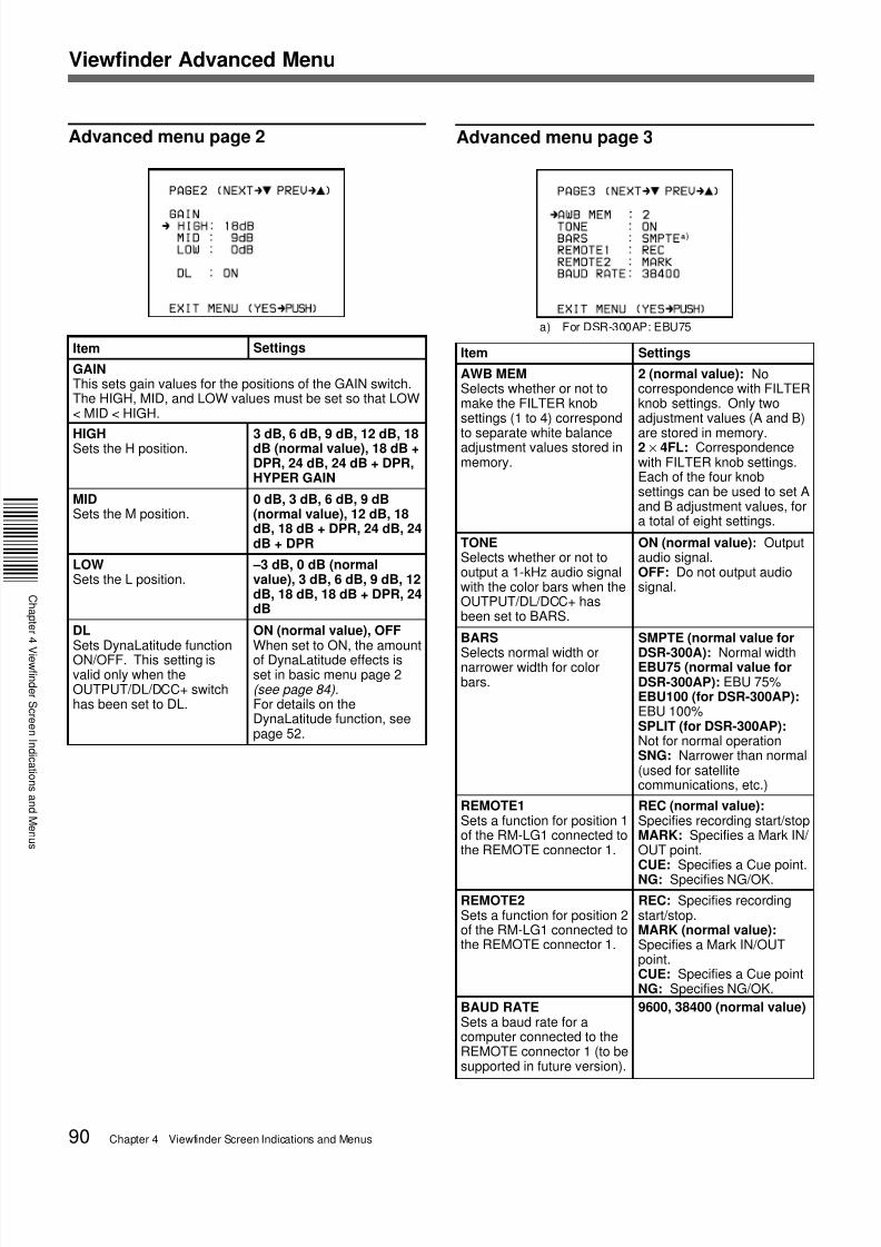
Advanced menu page 2 Advanced menu page 3
a) For DSR-300AP: EBU75
Item Settings
GAINThis sets gain values for the positions of the GAIN switch.The HIGH, MID, and LOW values must be set so that LOW< MID < HIGH.
–3 dB, 0 dB (normalvalue), 3 dB, 6 dB, 9 dB, 12dB, 18 dB, 18 dB + DPR, 24dB
DLSets DynaLatitude functionON/OFF. This setting isvalid only when theOUTPUT/DL/DCC+ switchhas been set to DL.
ON (normal value), OFFWhen set to ON, the amountof DynaLatitude effects isset in basic menu page 2(see page 84).For details on theDynaLatitude function, seepage 52.
3 dB, 6 dB, 9 dB, 12 dB, 18dB (normal value), 18 dB +DPR, 24 dB, 24 dB + DPR,HYPER GAIN
Viewfinder Advanced Menu
Item
AWB MEMSelects whether or not tomake the FILTER knobsettings (1 to 4) correspond
to separate white balanceadjustment values stored inmemory.
2 (normal value): Nocorrespondence with FILTERknob settings. Only twoadjustment values (A and B)
are stored in memory.2 × 4FL: Correspondencewith FILTER knob settings.Each of the four knobsettings can be used to set Aand B adjustment values, fora total of eight settings.
TONESelects whether or not tooutput a 1-kHz audio signalwith the color bars when theOUTPUT/DL/DCC+ hasbeen set to BARS.
ON (normal value): Outputaudio signal.OFF: Do not output audiosignal.
BARS
Selects normal width ornarrower width for colorbars.
SMPTE (normal value for
DSR-300A): Normal widthEBU75 (normal value forDSR-300AP): EBU 75%EBU100 (for DSR-300AP):EBU 100%SPLIT (for DSR-300AP):Not for normal operationSNG: Narrower than normal(used for satellitecommunications, etc.)
REMOTE1Sets a function for position 1of the RM-LG1 connected tothe REMOTE connector 1.
REC (normal value):Specifies recording start/stopMARK: Specifies a Mark IN/ OUT point.CUE: Specifies a Cue point.NG: Specifies NG/OK.
REMOTE2Sets a function for position 2of the RM-LG1 connected tothe REMOTE connector 1.
9600, 38400 (normal value)
REC: Specifies recordingstart/stop.MARK (normal value):Specifies a Mark IN/OUTpoint.CUE: Specifies a Cue pointNG: Specifies NG/OK.
Settings
BAUD RATESets a baud rate for acomputer connected to theREMOTE connector 1 (to besupported in future version).
7/18/2019 Sony DSR-300A Operation Manual
http://slidepdf.com/reader/full/sony-dsr-300a-operation-manual 91/136Chapter 4 Viewfinder Screen Indications and Menus 91
C
a p t e
e
d e
S c e e
d c a t o
s a
d
e
u s
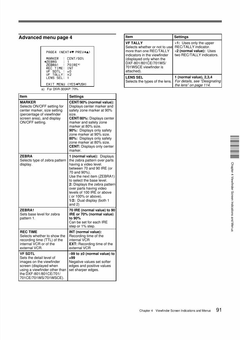
Advanced menu page 4
a) For DSR-300AP: 70%
Item
MARKERSelects ON/OFF setting forcenter marker, size setting(percentage of viewfinder
screen area), and displayON/OFF setting.
CENT/90% (normal value):Displays center marker andsafety zone marker at 90%size.
CENT/80%: Displays centermarker and safety zonemarker at 80% size.90%: Displays only safetyzone marker at 90% size.80%: Displays only safetyzone marker at 80% size.CENT: Displays only centermarker.
ZEBRASelects type of zebra patterndisplay.
1 (normal value): Displaysthe zebra pattern over partshaving a video level.between 70 and 90 IRE (or70 and 90%).Use the next item (ZEBRA1)to select the base level.2: Displays the zebra patternover parts having videolevels of 100 IRE or above( or 100% or above).1/2: Dual display (both 1and 2)
ZEBRA1Sets base level for zebrapattern 1.
70 IRE (normal value) to 90IRE or 70% (normal value)to 90%Can be set for each IREstep or 1% step.
INT (normal value):Recording time of theinternal VCREXT: Recording time of theexternal VCR
×1: Uses only the upperREC/TALLY indicator.×2 (normal value): Usestwo REC/TALLY indicators.
Settings
–99 to ±0 (normal value) to+99Negative values set softeredges and positive valuesset sharper edges.
VF TALLYSelects whether or not to usemore than one REC/TALLYindicators in the viewfinder
(displayed only when theDXF-801/801CE/701WS/ 701WSCE viewfinder isattached).
REC TIMESelects whether to show therecording time (TTL) of theinternal VCR or of theexternal VCR.
VF SDTLSets the detail level ofimages on the viewfinderscreen (displayed whenusing a viewfinder other thanthe DXF-801/801CE/701/ 701CE/701WS/701WSCE).
1 (normal value), 2,3,4For details, see “Designating the lens” on page 114.
Item Settings
LENS SELSelects the types of the lens.
7/18/2019 Sony DSR-300A Operation Manual
http://slidepdf.com/reader/full/sony-dsr-300a-operation-manual 92/13692 Chapter 4 Viewfinder Screen Indications and Menus
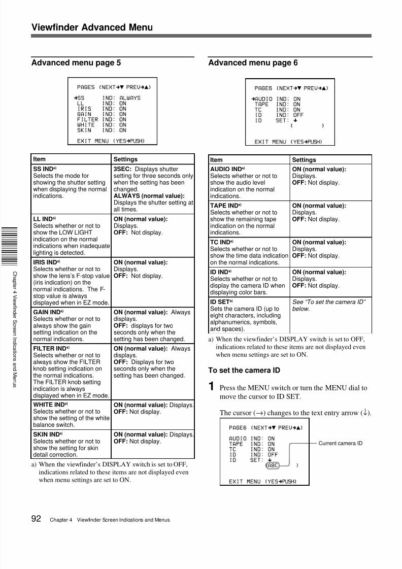
Advanced menu page 5
a) When the viewfinder’s DISPLAY switch is set to OFF,
indications related to these items are not displayed even
when menu settings are set to ON.
Item Settings
SS INDa)
Selects the mode forshowing the shutter settingwhen displaying the normalindications.
3SEC: Displays shuttersetting for three seconds onlywhen the setting has beenchanged.ALWAYS (normal value):Displays the shutter setting atall times.
LL INDa)
Selects whether or not toshow the LOW LIGHTindication on the normalindications when inadequatelighting is detected.
ON (normal value):Displays.OFF: Not display.
IRIS INDa)
Selects whether or not toshow the lens’s F-stop value(iris indication) on thenormal indications. The F-
stop value is alwaysdisplayed when in EZ mode.
ON (normal value):Displays.OFF: Not display.
GAIN INDa)
Selects whether or not toalways show the gainsetting indication on thenormal indications.
ON (normal value): Alwaysdisplays.OFF: displays for twoseconds only when thesetting has been changed.
FILTER INDa)
Selects whether or not toalways show the FILTERknob setting indication onthe normal indications.The FILTER knob settingindication is always
displayed when in EZ mode.
ON (normal value): Alwaysdisplays.OFF: Displays for twoseconds only when thesetting has been changed.
WHITE INDa)
Selects whether or not toshow the setting of the whitebalance switch.
ON (normal value): Displays.OFF: Not display.
SKIN INDa)
Selects whether or not toshow the setting for skindetail correction.
ON (normal value): Displays.OFF: Not display.
Advanced menu page 6
a) When the viewfinder’s DISPLAY switch is set to OFF,
indications related to these items are not displayed even
when menu settings are set to ON.
To set the camera ID
1 Press the MENU switch or turn the MENU dial to
move the cursor to ID SET.
The cursor (→) changes to the text entry arrow (↓).
Item Settings
AUDIO INDa)
Selects whether or not toshow the audio levelindication on the normalindications.
ON (normal value):Displays.OFF: Not display.
TAPE INDa)
Selects whether or not toshow the remaining tapeindication on the normalindications.
ON (normal value):Displays.OFF: Not display.
TC INDa)
Selects whether or not toshow the time data indicationon the normal indications.
ON (normal value):Displays.OFF: Not display.
ID INDa)
Selects whether or not todisplay the camera ID whendisplaying color bars.
ON (normal value):Displays.OFF: Not display.
ID SETa)
Sets the camera ID (up toeight characters, includingalphanumerics, symbols,and spaces).
See “To set the camera ID” below.
Current camera ID
Viewfinder Advanced Menu
7/18/2019 Sony DSR-300A Operation Manual
http://slidepdf.com/reader/full/sony-dsr-300a-operation-manual 93/136Chapter 4 Viewfinder Screen Indications and Menus 93
C
a p t e
e
d e
S c e e
d c a t o
s a
d
e
u s
2 Press and turn the MENU dial to move the text
entry arrow.
Turn the MENU dial upward to move the cursor to
the right or downward to move it to the left.
3 Press and turn the MENU dial to enter the desired
characters.
The displayed character changes as you turn the
dial.
4 Return to step 2 and repeat the text entry
procedure.
5 When you have finished entering the text, press
and turn the MENU dial to move the cursor to theparenthesis position.
This clears the displayed menu and returns to the
normal indications.
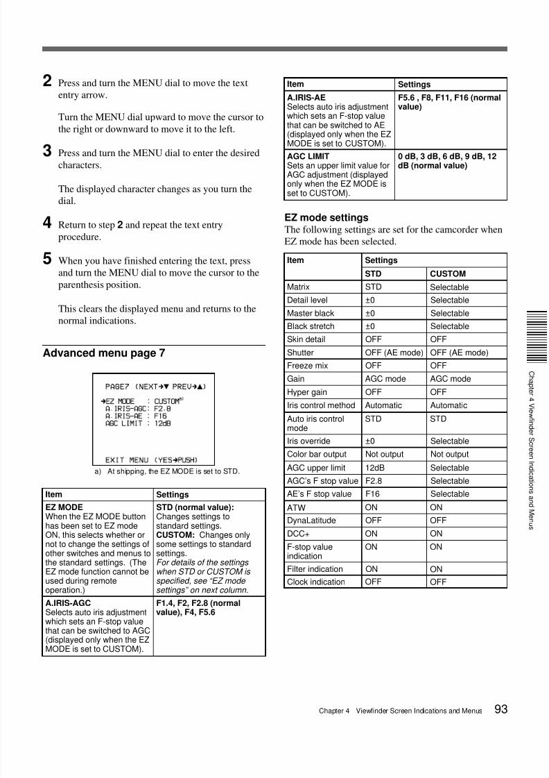
Advanced menu page 7
a) At shipping, the EZ MODE is set to STD.
Item Settings
EZ MODEWhen the EZ MODE buttonhas been set to EZ modeON, this selects whether or
not to change the settings ofother switches and menus tothe standard settings. (TheEZ mode function cannot beused during remoteoperation.)
STD (normal value):Changes settings tostandard settings.CUSTOM: Changes only
some settings to standardsettings.For details of the settings when STD or CUSTOM is specified, see “EZ mode settings” on next column.
A.IRIS-AGCSelects auto iris adjustmentwhich sets an F-stop valuethat can be switched to AGC(displayed only when the EZMODE is set to CUSTOM).
F1.4, F2, F2.8 (normalvalue), F4, F5.6
A.IRIS-AESelects auto iris adjustmentwhich sets an F-stop valuethat can be switched to AE
(displayed only when the EZMODE is set to CUSTOM).
F5.6 , F8, F11, F16 (normalvalue)
AGC LIMITSets an upper limit value forAGC adjustment (displayedonly when the EZ MODE isset to CUSTOM).
0 dB, 3 dB, 6 dB, 9 dB, 12dB (normal value)
EZ mode settingsThe following settings are set for the camcorder when
EZ mode has been selected.
Item Settings
STD CUSTOM
Matrix STD Selectable
Detail level ±0 Selectable
Master black ±0 Selectable
Black stretch ±0 Selectable
Skin detail OFF OFF
Shutter OFF (AE mode) OFF (AE mode)
ATW
Iris control method
Freeze mix OFF OFF
Gain AGC mode AGC mode
Hyper gain OFF OFF
Automatic AutomaticAuto iris controlmode
STD STD
Iris override ±0 Selectable
Color bar output Not output Not output
AGC upper limit 12dB Selectable
AGC’s F stop value F2.8 Selectable
AE’s F stop value F16 Selectable
ON
DynaLatitude OFF
DCC+
F-stop valueindication
ON
OFF
ON ON
ON ON
Filter indication ON ON
Item Settings
Clock indication OFF OFF
7/18/2019 Sony DSR-300A Operation Manual
http://slidepdf.com/reader/full/sony-dsr-300a-operation-manual 94/13694 Chapter 4 Viewfinder Screen Indications and Menus
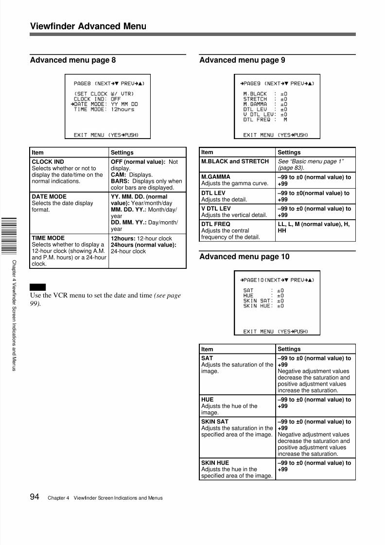
Advanced menu page 8
NoteUse the VCR menu to set the date and time (see page
99).
Item Settings
CLOCK INDSelects whether or not todisplay the date/time on thenormal indications.
OFF (normal value): Notdisplay.CAM: Displays.BARS: Displays only whencolor bars are displayed.
DATE MODESelects the date displayformat.
YY. MM. DD. (normalvalue): Year/month/dayMM. DD. YY.: Month/day/ yearDD. MM. YY.: Day/month/ year
TIME MODESelects whether to display a12-hour clock (showing A.M.and P.M. hours) or a 24-hourclock.
http://slidepdf.com/reader/full/sony-dsr-300a-operation-manual 100/136100 Chapter 5 Adjustments and Settings
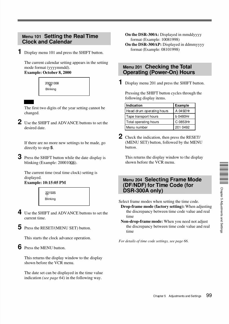
1 Display menu 204.
The menu number and the current frame mode
setting are shown.
Example: dF (drop-frame mode)
If the setting does not need to be changed, press
the MENU button to close the menu.
2 Press the SHIFT button to make the frame modestart blinking, then press the ADVANCE button.
This switches the frame mode display as shown
below.
Example: ndF (non-drop-frame mode)
3 Press the RESET/(MENU SET) button and thenthe MENU button.
The settings are recorded and the display window
returns to the display shown before the VCR menu.
Menu 206 Selecting BatteryCapacity Indication
This selects the indication type of battery capacity.
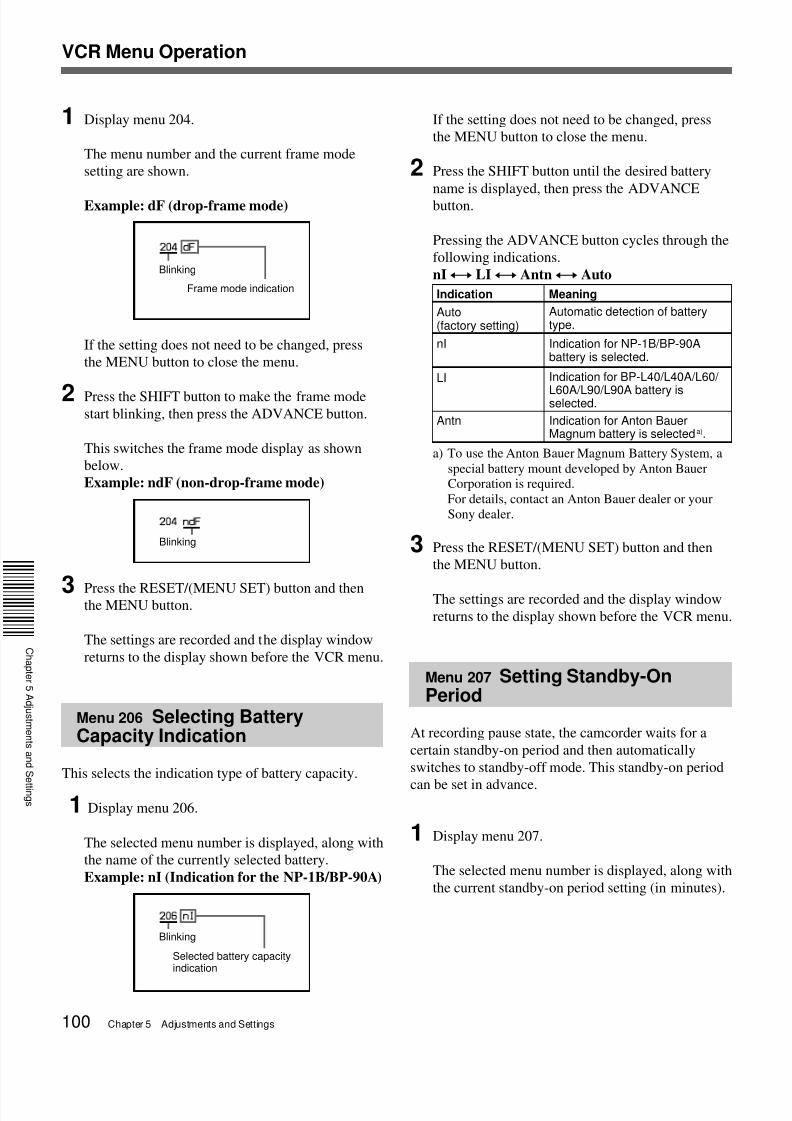
1 Display menu 206.
The selected menu number is displayed, along with
the name of the currently selected battery.
Example: nI (Indication for the NP-1B/BP-90A)
If the setting does not need to be changed, press
the MENU button to close the menu.
2 Press the SHIFT button until the desired battery
name is displayed, then press the ADVANCE
button.
Pressing the ADVANCE button cycles through the
following indications.
nIy LIy Antny Auto
a) To use the Anton Bauer Magnum Battery System, a
special battery mount developed by Anton BauerCorporation is required.
For details, contact an Anton Bauer dealer or your
Sony dealer.
3 Press the RESET/(MENU SET) button and then
the MENU button.
The settings are recorded and the display window
returns to the display shown before the VCR menu.
Menu 207 Setting Standby-OnPeriod
At recording pause state, the camcorder waits for a
certain standby-on period and then automatically
switches to standby-off mode. This standby-on period
can be set in advance.
1 Display menu 207.
The selected menu number is displayed, along with
the current standby-on period setting (in minutes).
Blinking
Blinking
Frame mode indicationIndication Meaning
LI Indication for BP-L40/L40A/L60/
L60A/L90/L90A battery isselected.
Antn Indication for Anton BauerMagnum battery is selected a).
nI Indication for NP-1B/BP-90Abattery is selected.
Blinking
Selected battery capacityindication
Auto(factory setting)
Automatic detection of batterytype.
VCR Menu Operation
7/18/2019 Sony DSR-300A Operation Manual
http://slidepdf.com/reader/full/sony-dsr-300a-operation-manual 101/136Chapter 5 Adjustments and Settings 101
C
a p t e
5
d j u s t
e
t s a
d S e t t
g s
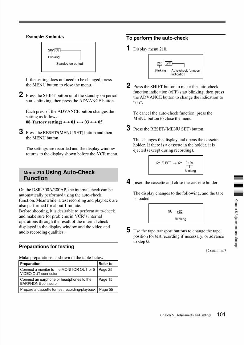
Example: 8 minutes
If the setting does not need to be changed, press
the MENU button to close the menu.
2 Press the SHIFT button until the standby-on period
starts blinking, then press the ADVANCE button.
Each press of the ADVANCE button changes the
setting as follows.
08 (factory setting)y 01y 03y 05
3 Press the RESET/(MENU SET) button and then
the MENU button.
The settings are recorded and the display window
returns to the display shown before the VCR menu.
Menu 210 Using Auto-CheckFunction
On the DSR-300A/300AP, the internal check can be
automatically performed using the auto-check
function. Meanwhile, a test recording and playback are
also performed for about 1 minute.
Before shooting, it is desirable to perform auto-check
and make sure for problems in VCR’s internal
operations through the result of the internal check
displayed in the display window and the video and
audio recording qualities.
Preparations for testing
Make preparations as shown in the table below.
To perform the auto-check
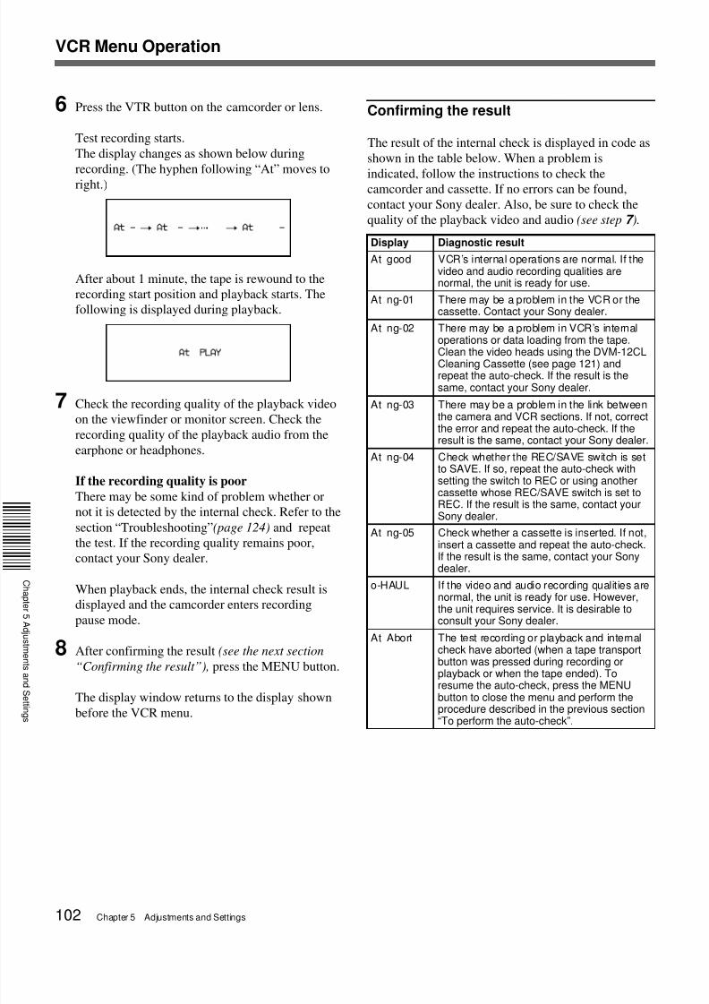
1 Display menu 210.
2 Press the SHIFT button to make the auto-check
function indication (oFF) start blinking, then press
the ADVANCE button to change the indication to
“on”.
To cancel the auto-check function, press the
MENU button to close the menu.
3 Press the RESET/(MENU SET) button.
This changes the display and opens the cassette
holder. If there is a cassette in the holder, it is
ejected (except during recording).
4 Insert the cassette and close the cassette holder.
The display changes to the following, and the tape
is loaded.
5 Use the tape transport buttons to change the tape
position for test recording if necessary, or advance
to step 6.
Blinking
Blinking
(Continued)
Blinking Auto-check functionindication
Blinking
Standby-on period
Preparation Refer to
Connect a monitor to the MONITOR OUT or SVIDEO OUT connector
Page 25
Connect an earphone or headphones to theEARPHONE connector
Page 15
Prepare a cassette for test recording/playback Page 55
7/18/2019 Sony DSR-300A Operation Manual
http://slidepdf.com/reader/full/sony-dsr-300a-operation-manual 102/136102 Chapter 5 Adjustments and Settings
6 Press the VTR button on the camcorder or lens.
Test recording starts.
The display changes as shown below during
recording. (The hyphen following “At” moves toright.)
After about 1 minute, the tape is rewound to the
recording start position and playback starts. The
following is displayed during playback.
7 Check the recording quality of the playback video
on the viewfinder or monitor screen. Check the
recording quality of the playback audio from the
earphone or headphones.
If the recording quality is poor
There may be some kind of problem whether or
not it is detected by the internal check. Refer to the
section “Troubleshooting”(page 124) and repeatthe test. If the recording quality remains poor,
contact your Sony dealer.
When playback ends, the internal check result is
displayed and the camcorder enters recording
pause mode.
8 After confirming the result (see the next section
“Confirming the result”), press the MENU button.
The display window returns to the display shownbefore the VCR menu.
Confirming the result
The result of the internal check is displayed in code as
shown in the table below. When a problem is
indicated, follow the instructions to check thecamcorder and cassette. If no errors can be found,
contact your Sony dealer. Also, be sure to check the
quality of the playback video and audio (see step 7 ).
Display Diagnostic result
At good VCR’s internal operations are normal. If thevideo and audio recording qualities arenormal, the unit is ready for use.
At ng-01 There may be a problem in the VCR or thecassette. Contact your Sony dealer.
At ng-02 There may be a problem in VCR’s internaloperations or data loading from the tape.
Clean the video heads using the DVM-12CLCleaning Cassette (see page 121) andrepeat the auto-check. If the result is thesame, contact your Sony dealer.
At ng-03 There may be a problem in the link betweenthe camera and VCR sections. If not, correctthe error and repeat the auto-check. If theresult is the same, contact your Sony dealer.
At ng-04 Check whether the REC/SAVE switch is setto SAVE. If so, repeat the auto-check withsetting the switch to REC or using anothercassette whose REC/SAVE switch is set toREC. If the result is the same, contact yourSony dealer.
At ng-05 Check whether a cassette is inserted. If not,insert a cassette and repeat the auto-check.If the result is the same, contact your Sonydealer.
o-HAUL If the video and audio recording qualities arenormal, the unit is ready for use. However,the unit requires service. It is desirable toconsult your Sony dealer.
At Abort The test recording or playback and internalcheck have aborted (when a tape transportbutton was pressed during recording orplayback or when the tape ended). Toresume the auto-check, press the MENUbutton to close the menu and perform theprocedure described in the previous section“To perform the auto-check”.
VCR Menu Operation
7/18/2019 Sony DSR-300A Operation Manual
http://slidepdf.com/reader/full/sony-dsr-300a-operation-manual 103/136Chapter 5 Adjustments and Settings 103
C
a p t e
5
d j u s t
e
t s a
d S e t t
g s
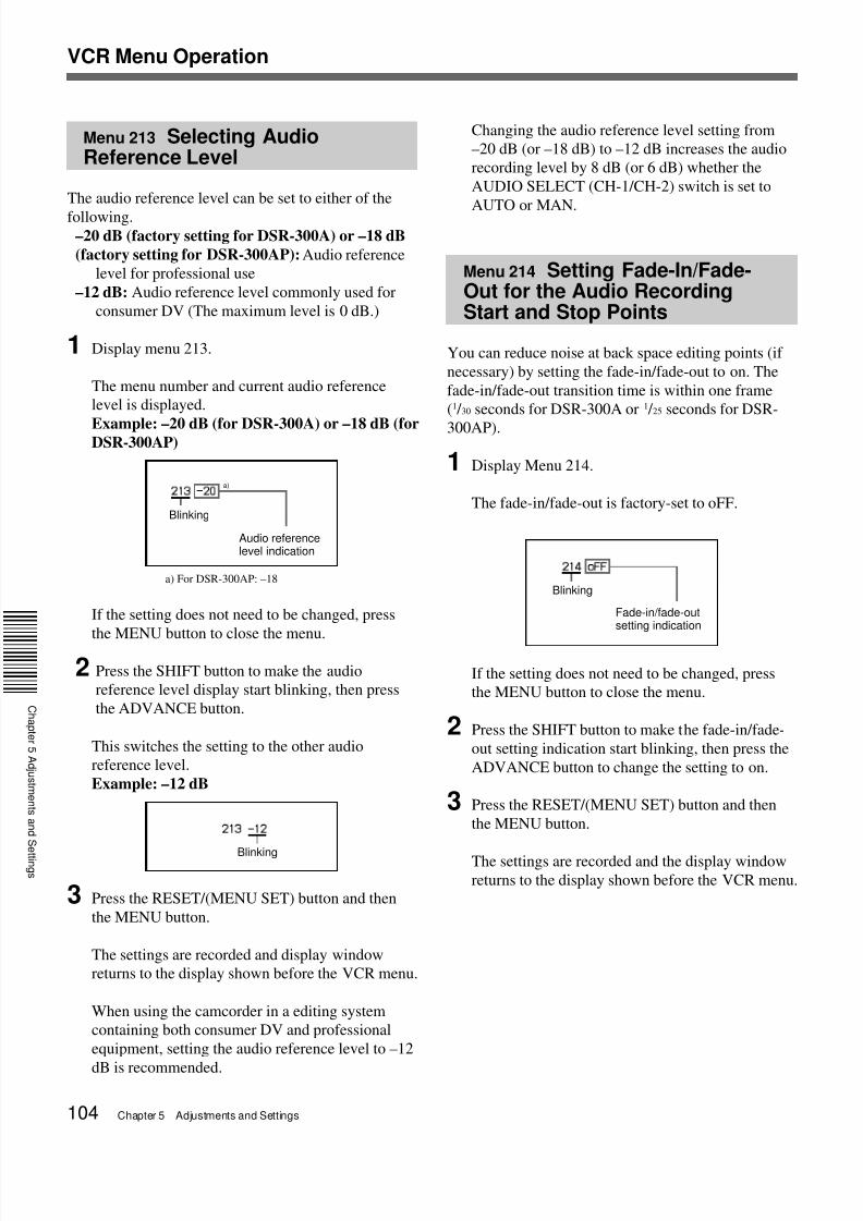
Menu 212 Selecting AudioRecording Mode
The audio recording mode can be set to either of the
following modes.48-kHz mode (factory setting): Enables two-
channel recording mode with 48-kHz sampling
frequency.
32-kHz mode: Enables four-channel recording mode
with 32-kHz sampling frequency (for CH-1 and
CH-2).
1 Display menu 212.
The menu number and current audio recording
mode is displayed.Example: 48 (2-channel mode with 48-kHz
sampling frequency)
If the setting does not need to be changed, press
the MENU button to close the menu.
2 Press the SHIFT button to make the audio
recording mode indication start blinking, then
press the ADVANCE button.
This switches the mode setting to the other audio
recording mode.
Example: 32 (4-channel mode with 32-kHz
sampling frequency)
3 Press the RESET/(MENU SET) button and then
the MENU button.
The settings are recorded and display window
returns to the display shown before the VCR menu.
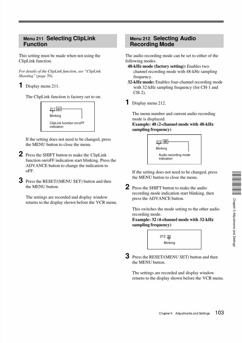
Menu 211 Selecting ClipLinkFunction
This setting must be made when not using the
ClipLink function.
For details of the ClipLink function, see “ClipLink
Shooting” (page 70).
1 Display menu 211.
The ClipLink function is factory-set to on.
If the setting does not need to be changed, press
the MENU button to close the menu.
2 Press the SHIFT button to make the ClipLink
function on/oFF indication start blinking. Press the
ADVANCE button to change the indication to
oFF.
3 Press the RESET/(MENU SET) button and thenthe MENU button.
The settings are recorded and display window
returns to the display shown before the VCR menu.
Blinking
Audio recording modeindication
Blinking
ClipLink function on/oFFindication
Blinking
7/18/2019 Sony DSR-300A Operation Manual
http://slidepdf.com/reader/full/sony-dsr-300a-operation-manual 104/136104 Chapter 5 Adjustments and Settings
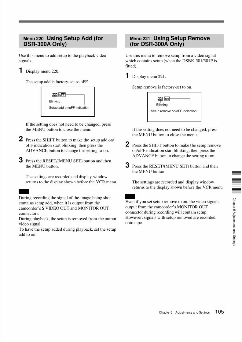
Menu 213 Selecting AudioReference Level
The audio reference level can be set to either of the
following.–20 dB (factory setting for DSR-300A) or –18 dB
(factory setting for DSR-300AP): Audio reference
level for professional use
–12 dB: Audio reference level commonly used for
consumer DV (The maximum level is 0 dB.)
1 Display menu 213.
The menu number and current audio reference
level is displayed.
Example: –20 dB (for DSR-300A) or –18 dB (forDSR-300AP)
a) For DSR-300AP: –18
If the setting does not need to be changed, press
the MENU button to close the menu.
2 Press the SHIFT button to make the audio
reference level display start blinking, then press
the ADVANCE button.
This switches the setting to the other audio
reference level.
Example: –12 dB
3 Press the RESET/(MENU SET) button and then
the MENU button.
The settings are recorded and display window
returns to the display shown before the VCR menu.
When using the camcorder in a editing system
containing both consumer DV and professional
equipment, setting the audio reference level to –12
dB is recommended.
Changing the audio reference level setting from
–20 dB (or –18 dB) to –12 dB increases the audio
recording level by 8 dB (or 6 dB) whether the
AUDIO SELECT (CH-1/CH-2) switch is set to
AUTO or MAN.
Menu 214 Setting Fade-In/Fade-Out for the Audio RecordingStart and Stop Points
You can reduce noise at back space editing points (if
necessary) by setting the fade-in/fade-out to on. The
fade-in/fade-out transition time is within one frame
(1 / 30 seconds for DSR-300A or 1 / 25 seconds for DSR-
300AP).
1 Display Menu 214.
The fade-in/fade-out is factory-set to oFF.
If the setting does not need to be changed, press
the MENU button to close the menu.
2 Press the SHIFT button to make the fade-in/fade-
out setting indication start blinking, then press the
ADVANCE button to change the setting to on.
3 Press the RESET/(MENU SET) button and then
the MENU button.
The settings are recorded and the display window
returns to the display shown before the VCR menu.
Blinking
a)
Audio referencelevel indication
Blinking
Blinking
Fade-in/fade-outsetting indication
VCR Menu Operation
7/18/2019 Sony DSR-300A Operation Manual
http://slidepdf.com/reader/full/sony-dsr-300a-operation-manual 105/136Chapter 5 Adjustments and Settings 105
C
a p t e
5
d j u s t
e
t s a
d S e t t
g s
Menu 220 Using Setup Add (forDSR-300A Only)
Use this menu to add setup to the playback video
signals.
1 Display menu 220.
The setup add is factory-set to oFF.
If the setting does not need to be changed, press
the MENU button to close the menu.
2 Press the SHIFT button to make the setup add on/
oFF indication start blinking, then press the
ADVANCE button to change the setting to on.
3 Press the RESET/(MENU SET) button and then
the MENU button.
The settings are recorded and display window
returns to the display shown before the VCR menu.
Note
During recording the signal of the image being shot
contains setup add, when it is output from the
camcorder’s S VIDEO OUT and MONITOR OUT
connectors.
During playback, the setup is removed from the output
video signal.
To have the setup added during playback, set the setup
add to on.
Blinking
Setup add on/oFF indication
Menu 221 Using Setup Remove(for DSR-300A Only)
Use this menu to remove setup from a video signal
which contains setup (when the DSBK-501/501P isfitted).
1 Display menu 221.
Setup remove is factory-set to on.
If the setting does not need to be changed, press
the MENU button to close the menu.
2 Press the SHIFT button to make the setup remove
on/oFF indication start blinking, then press the
ADVANCE button to change the setting to on.
3 Press the RESET/(MENU SET) button and then
the MENU button.
The settings are recorded and display window
returns to the display shown before the VCR menu.
Note
Even if you set setup remove to on, the video signals
output from the camcorder’s MONITOR OUT
connector during recording will contain setup.
However, signals with setup removed are recorded
onto tape.
Blinking
Setup remove on/oFF indication
7/18/2019 Sony DSR-300A Operation Manual
http://slidepdf.com/reader/full/sony-dsr-300a-operation-manual 106/136106 Chapter 5 Adjustments and Settings
1 Make the following settings.
• POWER switch: ON
• OUTPUT/DL/DCC+ switch: one of the CAM
positions
• Lens iris selector: A (automatic)
• ATW button: off
2 Set the FILTER control according to the lighting
conditions. (See page 51.)
3 Set the W. BAL switch to A or B.
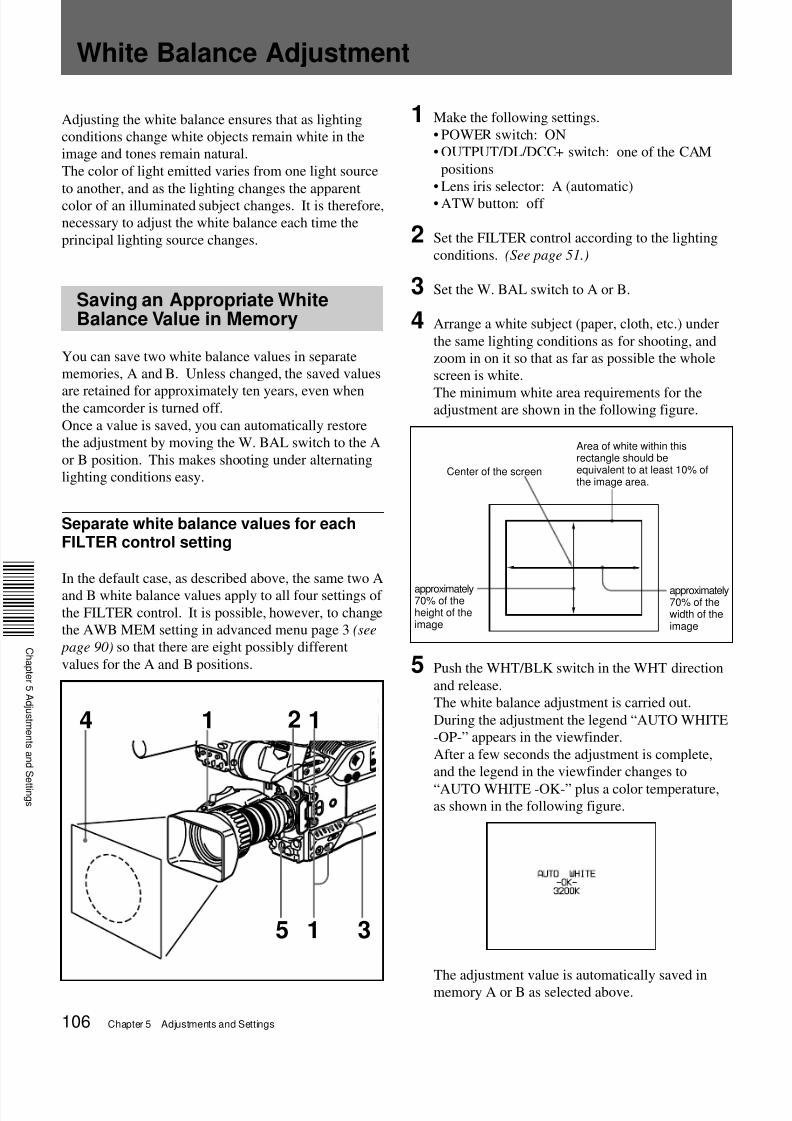
4 Arrange a white subject (paper, cloth, etc.) under
the same lighting conditions as for shooting, and
zoom in on it so that as far as possible the whole
screen is white.
The minimum white area requirements for theadjustment are shown in the following figure.
5 Push the WHT/BLK switch in the WHT direction
and release.
The white balance adjustment is carried out.
During the adjustment the legend “AUTO WHITE
-OP-” appears in the viewfinder.
After a few seconds the adjustment is complete,
and the legend in the viewfinder changes to
“AUTO WHITE -OK-” plus a color temperature,as shown in the following figure.
The adjustment value is automatically saved inmemory A or B as selected above.
Adjusting the white balance ensures that as lighting
conditions change white objects remain white in the
image and tones remain natural.
The color of light emitted varies from one light source
to another, and as the lighting changes the apparent
color of an illuminated subject changes. It is therefore,
necessary to adjust the white balance each time the
principal lighting source changes.
Saving an Appropriate WhiteBalance Value in Memory
You can save two white balance values in separate
memories, A and B. Unless changed, the saved values
are retained for approximately ten years, even whenthe camcorder is turned off.
Once a value is saved, you can automatically restore
the adjustment by moving the W. BAL switch to the A
or B position. This makes shooting under alternating
lighting conditions easy.
Separate white balance values for eachFILTER control setting
In the default case, as described above, the same two A
and B white balance values apply to all four settings of
the FILTER control. It is possible, however, to change
the AWB MEM setting in advanced menu page 3 (see
page 90) so that there are eight possibly different
values for the A and B positions.
Center of the screen
Area of white within thisrectangle should beequivalent to at least 10% ofthe image area.
White Balance Adjustment
1 2 1
5 1 3
4
approximately70% of theheight of theimage
approximately70% of thewidth of theimage
7/18/2019 Sony DSR-300A Operation Manual
http://slidepdf.com/reader/full/sony-dsr-300a-operation-manual 107/136Chapter 5 Adjustments and Settings 107
C
a p t e
5
d j u s t
e
t s a
d S e t t
g s
To save the white balance adjustment for different
lighting conditions, repeat steps 2 to 4 above. You can
save two different values for the white balance, in
memories A and B.
Note
The color temperature display is an approximate guide.
There is a margin of error in the displayed color
temperature when the white balance is adjusted on
another DSR-300A/300AP, camera, or camcorder,
even under the same conditions.
The margin of error is higher for higher temperatures.
To recall a white balance value from memoryBefore beginning shooting, set the W. BAL switch to
the A or B position. This automatically sets the
camcorder to the white balance adjustment saved inthe corresponding memory.
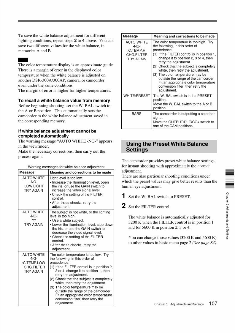
If white balance adjustment cannot becompleted automaticallyThe warning message “AUTO WHITE -NG-” appears
in the viewfinder.
Make the necessary corrections, then carry out the
process again.
Warning messages for white balance adjustment
Using the Preset White BalanceSettings
The camcorder provides preset white balance settings,
for instant shooting with approximately the correct
adjustment.
There are also particular shooting conditions underwhich the preset values may give better results than the
human eye adjustment.
1 Set the W. BAL switch to PRESET.
2 Set the FILTER control.
The white balance is automatically adjusted for
3200 K when the FILTER control is in position 1
and for 5600 K in position 2, 3 or 4.
You can change those values (3200 K and 5600 K)
to other values in basic menu page 2 (See page 84).
BARS
AUTO WHITE-NG-
:C.TEMP.HICHG.FILTER
TRY AGAIN
The color temperature is too high. Trythe following, in this order ofprecedence.(1) If the FILTER control is in position 1,
change it to position 2, 3 or 4, thenretry the adjustment.
(2) Check that the subject is completelywhite, then retry the adjustment.
(3) The color temperature may beoutside the range of the camcorder.Fit an appropriate color temperatureconversion filter, then retry theadjustment.
The W. BAL switch is in the PRESETposition.Move the W. BAL switch to the A or Bposition.
WHITE:PRESET
The camcorder is outputting a color bar
signal.Move the OUTPUT/DL/DCC+ switch toone of the CAM positions.
Message Meaning and corrections to be made
AUTO WHITE-NG-
:LOW LIGHTTRY AGAIN
Light level is too low.• Increase the illumination level, open
the iris, or use the GAIN switch toincrease the video signal level.
• Check the setting of the FILTERcontrol.
• After these checks, retry theadjustment.
AUTO WHITE-NG-
: ??TRY AGAIN
The subject is not white, or the lightinglevel is too high.
• Use a white subject.• Lower the illumination level, stop down
the iris, or use the GAIN switch to
decrease the video signal level.• Check the setting of the FILTER
control.• After these checks, retry the
adjustment.
AUTO WHITE-NG-
:C.TEMP.LOWCHG.FILTERTRY AGAIN
The color temperature is too low. Trythe following, in this order ofprecedence.(1) If the FILTER control is in position 2,
3 or 4, change it to position 1, thenretry the adjustment.
(2) Check that the subject is completelywhite, then retry the adjustment.
(3) The color temperature may be
outside the range of the camcorder.Fit an appropriate color temperatureconversion filter, then retry theadjustment.
Message Meaning and corrections to be made
7/18/2019 Sony DSR-300A Operation Manual
http://slidepdf.com/reader/full/sony-dsr-300a-operation-manual 108/136108 Chapter 5 Adjustments and Settings
Light Sources and ColorTemperature
Adjustment of the white balance to match the light
source is essential to ensure correct color rendering.The color of a light source is indicated as a color
temperature in kelvins (K). It is higher for bluish light,
and lower for reddish light. When the camcorder is
shipped it is adjusted for use with video lights (studio
lamps with a color temperature of 3200 K). For use
with other light sources, therefore, adjustment is
required.
First use the FILTER control to set the approximate
color temperature, then carry out white balance
adjustment.
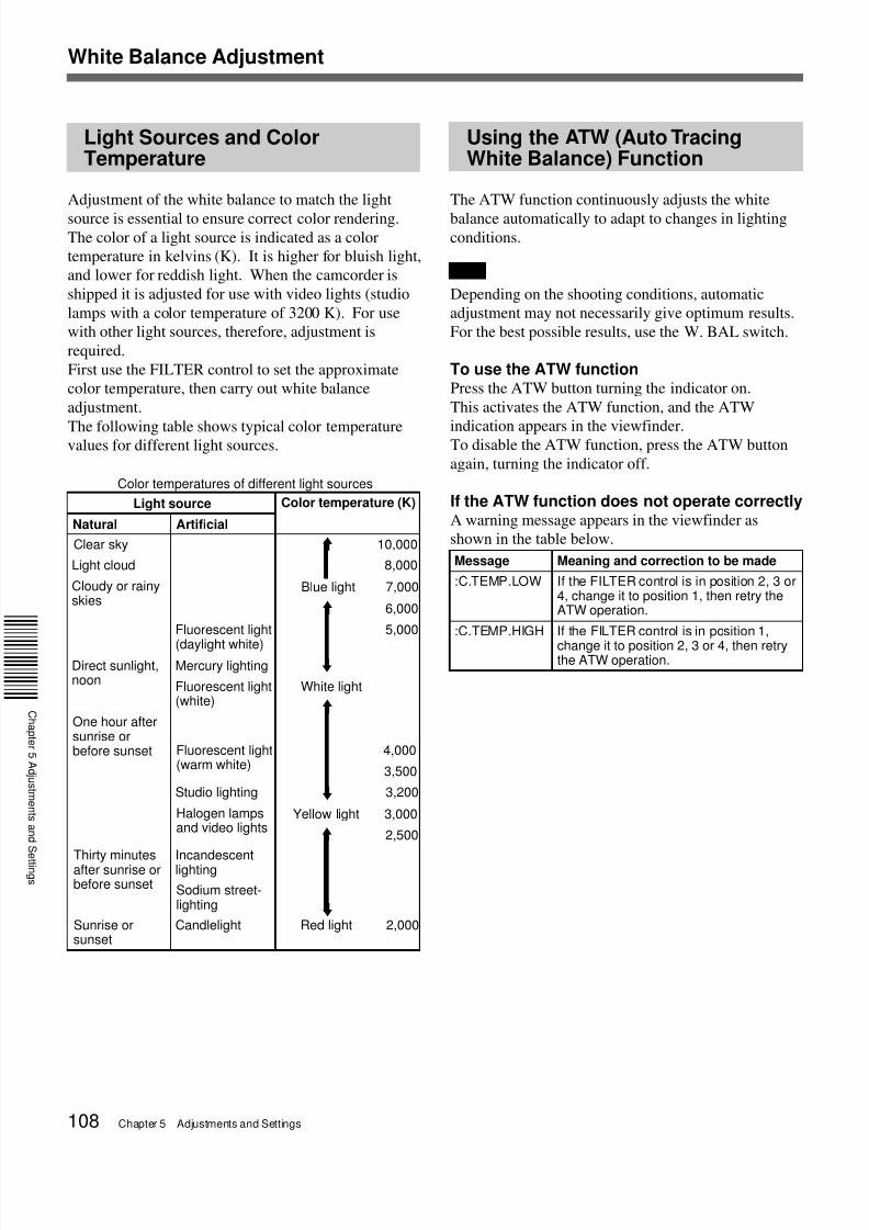
The following table shows typical color temperaturevalues for different light sources.
Color temperatures of different light sources
Light source
Natural Artificial
Color temperature (K)
Clear sky 10,000
Light cloud 8,000
Cloudy or rainyskies
Blue light 7,000
6,000
Fluorescent light
(daylight white)
5,000
Direct sunlight,noon
Mercury lighting
Fluorescent light(white)
White light
One hour aftersunrise orbefore sunset Fluorescent light
(warm white)4,000
3,500
Studio lighting 3,200
Halogen lampsand video lights
Yellow light 3,000
2,500
Thirty minutesafter sunrise orbefore sunset
Incandescentlighting
Sodium street-lighting
Sunrise orsunset
Candlelight Red light 2,000
M
M
m
M
m
M
m
Using the ATW (Auto TracingWhite Balance) Function
The ATW function continuously adjusts the white
balance automatically to adapt to changes in lightingconditions.
Note
Depending on the shooting conditions, automatic
adjustment may not necessarily give optimum results.
For the best possible results, use the W. BAL switch.
To use the ATW functionPress the ATW button turning the indicator on.
This activates the ATW function, and the ATW
indication appears in the viewfinder.To disable the ATW function, press the ATW button
again, turning the indicator off.
If the ATW function does not operate correctlyA warning message appears in the viewfinder as
shown in the table below.
White Balance Adjustment
Message Meaning and correction to be made
:C.TEMP.LOW If the FILTER control is in position 2, 3 or4, change it to position 1, then retry theATW operation.
:C.TEMP.HIGH If the FILTER control is in position 1,
change it to position 2, 3 or 4, then retrythe ATW operation.
7/18/2019 Sony DSR-300A Operation Manual
http://slidepdf.com/reader/full/sony-dsr-300a-operation-manual 109/136Chapter 5 Adjustments and Settings 109
C
a p t e
5
d j u s t
e
t s a
d S e t t
g s
12
If black balance adjustment cannot becompleted automaticallyThe warning message “AUTO BLACK -NG-” appears
in the viewfinder.
Make the necessary corrections, then carry out the
process again.
Warning messages for black balance adjustment
Message Meaning and corrections to be made
AUTO BLACK-NG-
: IRISNOT CLOSEDTRY AGAIN
The lens iris did not close fully.Check whether the lens cable isconnected properly, and whether there isa fault in the lens. If a second attempt tocarry out the adjustment fails, consultyour Sony dealer.
AUTO BLACK-NG-
: ??TRY AGAIN
The iris opened during adjustment orthere is a hardware error.
Close the iris and try again. If this fails,consult your Sony dealer.
Black Balance Adjustment
Correct adjustment of the black balance is important
for optimum operation of a camcorder. It is necessary
when using the camcorder for the first time or after a
significant period out of use, and also when there has
been a sudden change in temperature.
The adjustment value is saved in memory, and
readjustment is not normally necessary after powering
the camcorder off or simply when lighting conditions
change.
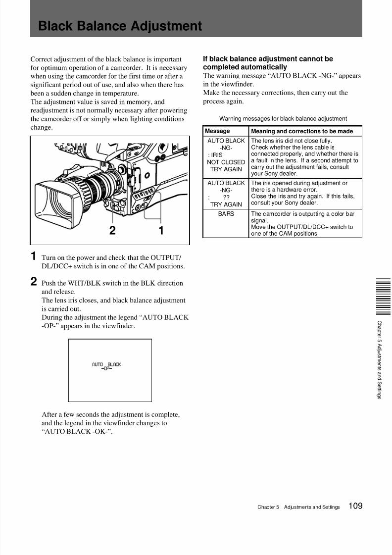
1 Turn on the power and check that the OUTPUT/
DL/DCC+ switch is in one of the CAM positions.
2 Push the WHT/BLK switch in the BLK direction
and release.The lens iris closes, and black balance adjustment
is carried out.
During the adjustment the legend “AUTO BLACK
-OP-” appears in the viewfinder.
After a few seconds the adjustment is complete,
and the legend in the viewfinder changes to
“AUTO BLACK -OK-”.
BARS The camcorder is outputting a color barsignal.Move the OUTPUT/DL/DCC+ switch toone of the CAM positions.
7/18/2019 Sony DSR-300A Operation Manual
http://slidepdf.com/reader/full/sony-dsr-300a-operation-manual 110/136110 Chapter 5 Adjustments and Settings
21 3
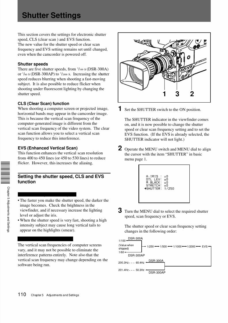
1 Set the SHUTTER switch to the ON position.
The SHUTTER indicator in the viewfinder comes
on, and it is now possible to change the shutter
speed or clear scan frequency setting and to set the
EVS function. (If the EVS is already selected, the
SHUTTER indicator will not light.)
2 Operate the MENU switch and MENU dial to align
the cursor with the item “SHUTTER” in basic
menu page 1.
3 Turn the MENU dial to select the required shutter
speed, scan frequency or EVS.
The shutter speed or clear scan frequency settingchanges in the following order:
200.3Hz • • • 60.4Hz
1/100
EVS
1/60
1/250 1/500 1/1000 1/2000
DSR-300A
201.4Hz • • • 50.3Hz
DSR-300AP
DSR-300A
DSR-300AP
(Value whenshipped)
Shutter Settings
This section covers the settings for electronic shutter
speed, CLS (clear scan ) and EVS function.
The new value for the shutter speed or clear scan
frequency and EVS setting remains set until changed,
even when the camcorder is powered off.
Shutter speedsThere are five shutter speeds, from 1 / 100 s (DSR-300A)
or 1 / 60 s (DSR-300AP) to 1 / 2000 s. Increasing the shutter
speed reduces blurring when shooting a fast-moving
subject. It is also possible to reduce flicker when
shooting under fluorescent lighting by changing the
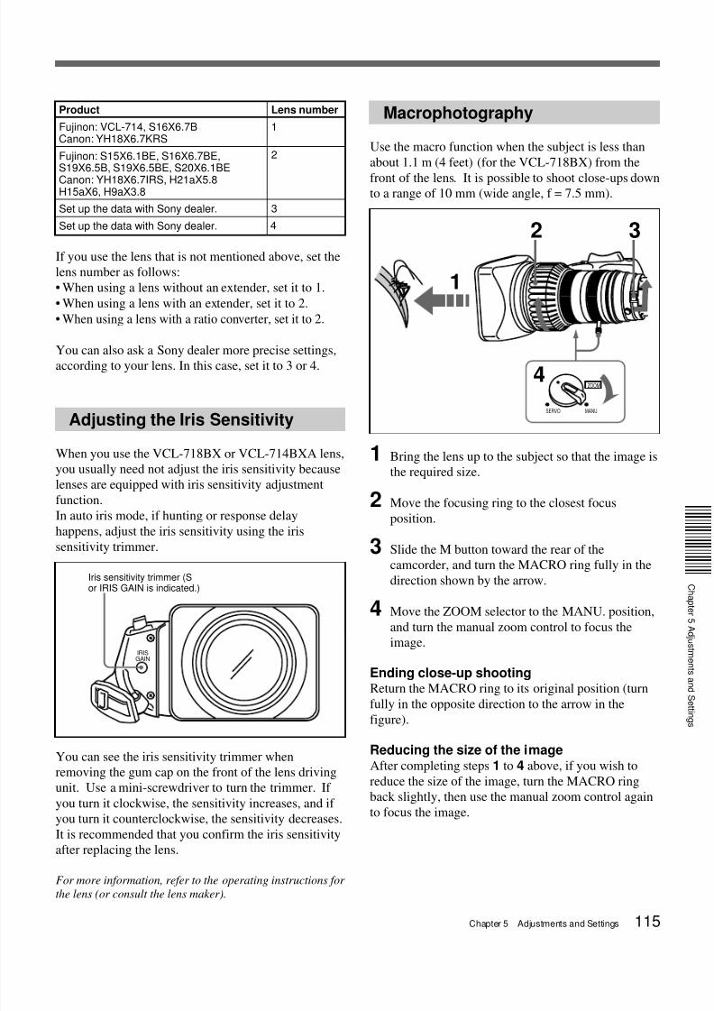
shutter speed.
CLS (Clear Scan) functionWhen shooting a computer screen or projected image,
horizontal bands may appear in the camcorder image.This is because the vertical scan frequency of the
computer-generated image is different from the
vertical scan frequency of the video system. The clear
scan function allows you to select a vertical scan
frequency to reduce this interference.
EVS (Enhanced Vertical Scan)This function enhances the vertical scan resolution
from 400 to 450 lines (or 450 to 530 lines) to reduce
flicker. However, this increases the aliasing.
Setting the shutter speed, CLS and EVSfunction
Notes on setting the shutter speed
• The faster you make the shutter speed, the darker the
image becomes. Check the brightness in the
viewfinder, and if necessary increase the lighting
level or adjust the iris.
• When the shutter speed is very fast, shooting a high
intensity subject may cause long vertical tails toappear on the highlights (smear).
Note on setting the CLS function
The vertical scan frequencies of computer screens
vary, and it may not be possible to eliminate the
interference patterns entirely. Note also that the
vertical scan frequency may change depending on the
software being run.
7/18/2019 Sony DSR-300A Operation Manual
http://slidepdf.com/reader/full/sony-dsr-300a-operation-manual 111/136Chapter 5 Adjustments and Settings 111
C
a p t e
5
d j u s t
e
t s a
d S e t t
g s
When using the clear scan function
Watching the monitor screen, adjust the frequency
to give minimum interference.
If there is a black band in the monitor image,
reduce the frequency, and if there is a white band,
increase the frequency.
To return from the basic menu to the normalindicationsPress the MENU switch as many times as necessary
until the normal indications appear. The new setting
of the shutter speed or clear scan frequency appears in
the normal screen display.
When shooting is finishedSet the SHUTTER switch to the OFF position.
The SHUTTER indicator in the viewfinder goes off.
7/18/2019 Sony DSR-300A Operation Manual
http://slidepdf.com/reader/full/sony-dsr-300a-operation-manual 112/136112 Chapter 5 Adjustments and Settings
Viewfinder Screen Adjustments
The following adjustments are provided to improve the
visibility of the viewfinder screen.
Although these adjustments may make the viewfinder
image clearer, they have no effect on the output video
signal from the camcorder.
Adjusting the eyepiece focus
Depending on the eyesight of the operator — whether
longsighted or shortsighted — the optimal position of
the viewfinder image varies. Adjust the eyepiece
focus to get the clearest viewfinder image for your
eyesight. First focus the image with the lens, then
adjust the eyepiece focusing knob. The adjustment
range is from –3 to 0 diopters1) (default when shipped
is 0 diopters).
Using an optional part allows you to modify the
adjustment range to –2 to +1 diopters or –0.5 to +3
diopters.
For details, consult your Sony dealer.
Contrast and brightness adjustment
Carry out these adjustments with the color bars
displayed.
1 Set the OUTPUT/DL/DCC+ switch to the BARS
position.
The color bars appear in the viewfinder.
2 Watching the color bars, turn the CONTRAST and
BRIGHT controls to adjust the contrast and
brightness.
3 Return the OUTPUT/DL/DCC+ switch to its
original position.
Outline emphasis adjustment
Turning the PEAKING control changes the degree of
outline emphasis in the viewfinder image, to make
focusing easier.
1) Diopter: A unit to indicate the degree of convergence or
The time code setting is not possible. At the recording, the ClipLink function isset to on (meaning ClipLink shooting isallowed) in menu 211, CONT is displayed
in the display window and the time codegenerator is in the REGEN mode.
Only the REGEN mode can be used forClipLink shooting. If you will not performClipLink shooting, set the ClipLink
function to oFF (see page 103).
The time code value does not advancethough the TC mode switch 1 or 2 is setto the F-RUN or DATE/TIME.
a) Optional accessory shoe kit is required for fitting. For details, consult your Sony dealer.b) Use when power consumption of the DSR-300A/300AP and accessories is 38 W or
lower.c) When power consumption is 38 W or higher due to fiting a video light (with power
consumption of 30 W or lower) to the DSR-300A/300AP, use the AC-DN2A (150 W orlower).
d) It is recommended that the BP-L40/L40A be used at 30 W or less (See page 47).