Abstract— Furnace and convective pass slagging and fouling have a negative effect on boiler performance and emissions. The purpose of soot blowers is to keep the heat transfer surface clean so as to contribute towards optimal performance of the boiler. Excessive soot blowing can cause increased maintenance in fossil-fired boilers. Soot blowers perform on-line cleaning of localized areas consuming substantial amounts of costly high pressure Main Steam; this cost motivates the study of soot blowers and development of improved soot blowing strategies. Boiler operators typically follow one continuous soot blowing sequence. Most rely on manufacturer’s recommendations, while some try to improve soot blower activation strategy by employing a trial-and-error approach. Considering the importance of soot blowing on plant operations and availability, soot blower operations need more attention. The Jindal Power Limited – different Dept. teamed up and has taken the initiative to perform a study on soot blower optimization by implementing pattern wise blowing. For this, different combination of tiers wise SB was done and the requirement and effectiveness of each tier was observed by studying different parameters and developed a practical, knowledge-based approach to soot blowing optimization and has implemented it in Unit # 3 & Unit # 1 of 4 x 250 MW, OPJSTPP. This approach can deal with the reduction of soot blower activation frequency, and steam temperature control. This paper describes the approach; implementation on a 250 MW tangentially fired boiler, operating experience, and benefits to the plants.
Keywords— Soot Blower, Slagging
I. INTRODUCTION
LL coals contain mineral matter in coal ash. Furnace slagging occurs as molten or sticky fly ash particles come in contact with the furnace walls or other radiant surfaces and form deposits due to the quenching
effect of the tube wall. Slag deposits reduce heat transfer to the furnace walls, and increase the amount of heat available to the convection pass. This results in a higher furnace exit gas temperature (FEGT) and, for subcritical boilers, in a higher steam temperature, de-superheating spray flows and NOx emissions. Deposition of ash on tubes or heat transfer surfaces in the convective pass reduces heat transfer in that part of the boiler. The convective pass fouling results in less heat is transfer to the working fluid, a decrease in steam temperature and de-superheating spray flows, and in an increase in flue gas temperature at the boiler exit.
The challenge in sootblowing optimization is to determine which sections of the boiler to clean and on what schedule, considering the factors such as tube life, sootblower steam or steam consumption and maintenance cost. For best boiler performance, it is important to maintain an optimal balance between furnace and convective pass heat transfer.
A. Basics of Soot Blowing
Sootblowing controls the level of ash and slag deposits on heat transfer sections. Sootblowers perform on-line cleaning of localized areas using high-pressure steam or air. Wall blowers and water cannons remove slag from furnace water walls, while retractable blowers clean the convective pass of the boiler (including the air preheater). Furnace cleaning increases radiation heat transfer to water walls and reduces the FEGT. This decreases the amount of heat that is available to the convective pass. Therefore, over-cleaning of furnace walls
Yashpal Sahu, CEEPI, Jindal Power Limited, Tamnar, Raigarh
Pooja Agrawal, CEEPI, Jindal Power Limited, Tamnar, Raigarh
Amit Pandey, CEEPI, Jindal Power Limited, Tamnar, Raigarh
MD Shahabuddin, CEEPI, Jindal Power Limited, Tamnar, Raigarh
Soot Blowing Optimization: Field Experience
Yashpal Sahu, Pooja Agrawal, Amit Pandey and MD Shahabuddin
A
National Seminar on Prospects and Challenges of Electrical Power Industry in India - NSPCEPII 347
can result in low steam temperatures (below design level) with resulting heat rate penalties and increased moisture levels and erosion damage in last stages of the low-pressure turbine. Reduced reheat steam temperature also results in lower turbine and unit power output.
II. JPL APPROACH TO SOOT BLOWING OPTIMIZATION
JPL has developed a sootblowing optimization approach, described in References [1 to 47], for balancing furnace and convection pass heat transfer to improve boiler performance, reduce NOx emissions, and minimize disturbances caused by sootblower activation.
The JPL sootblowing optimization approach depends on a database describing the effects of sootblower activation on parameters, such as cleanliness of heat transfer surfaces, steam temperatures, attemperating sprays, and other parameters of interest. The sootblower characterization database (SBCD), created from a series of sootblower characterization tests, contains of the effect of one sootblower or sootblower group at a time on parameters of interest.
III. SOOT BLOWERS OPTIMIZATION IN BOILERS
There are many methods used for optimization of wall blower operation in boiler furnace, like the manual method, heat flux measurement method, and the automated method. The manual method is discussed as this will bring out the philosophy involved in optimizing wall blower operation.
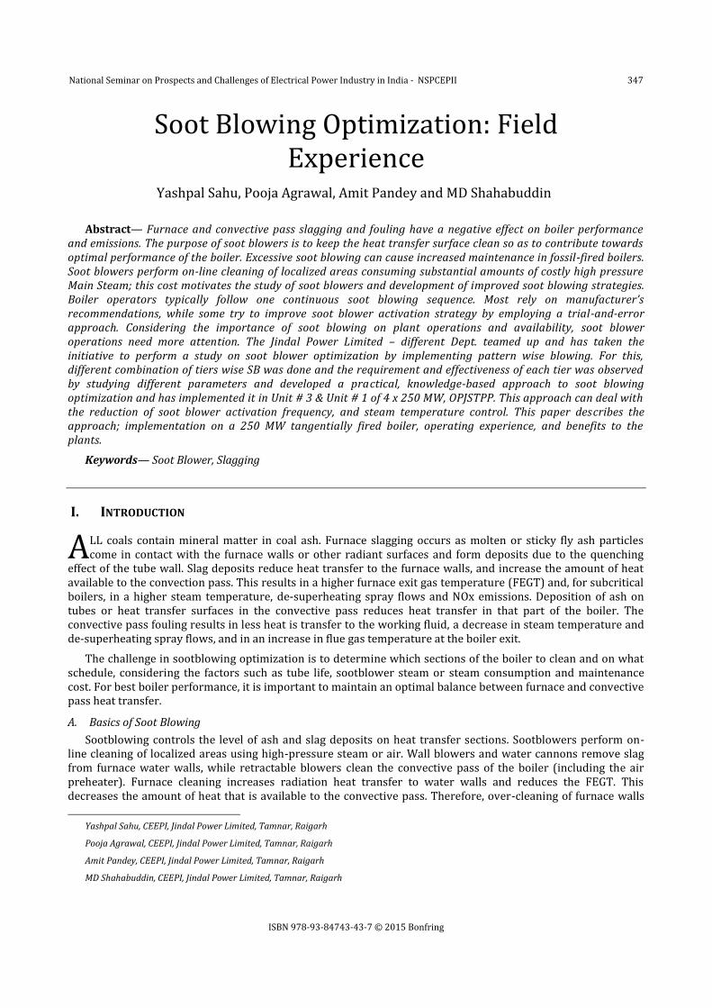
Wall blowers are provided in boilers to clean the furnace wall deposits. They seldom find use in oil and gas fired boilers. The deposition and slagging in boiler furnace is required to be removed from the furnace walls at regular intervals. The interval period will depend on the area of deposition and the severity of deposition. Steam wall blowers are found to be very efficient in removing the furnace wall deposits.
In JPL Stage-I boiler of around 825t/hr capacity, the total number of soot blowers are 90. In this, around 56 numbers are wall blowers. The frequency of soot blowing dependsupon the type of coal being fired. However the operating group must remember that the initial suggested sequence and frequency is more general and has to be adapted to each boiler. The purpose of these soot blowers is to keep the heat transfer surface clean so as to contribute towards optimal performance of the boiler.
Fig. 1
National Seminar on Prospects and Challenges of Electrical Power Industry in India - NSPCEPII 348
B. Effect Of The Soot Blower On Boiler Performance
Removes the deposits on the furnace wall and ensures good heat transfer in the furnace region The furnace outlet temperature slowly ramps up after wall blowing as time lapses Super heater spray quantity is seen to increase with time lapse after wall blowing Increases the bottom ash quantity depending upon the deposition on furnace walls Increases furnace tube material loss if blowing is done too frequently without any deposits. This leads to
boiler outage or increased maintenance In the case of water lancers for removing molten slag, while operating there will be a large dip in generation
for the same heat input. This is mainly due to the increased boiler losses
C. Measures To Be Considered
Before taking up wall blower optimization, the following has to be ensured:
All wall blowers are set to the right steam pressure recommended by the designer Check the alignment of the wall blower with respect to the furnace walls Ensure at least 50 degree centigrade of super heat in the steam being used. This is to prevent damage of
the furnace walls due to wet team impingement. All wall blowers are operational It is of great help if the boiler furnace walls are photographed just after a planned shutdown. Before
shutting down the boiler, do not wall blow the furnace for one full sequence. This ensures deposit collection on the walls between the adopted frequencies. While shutting down the boiler ensure minimal thermal shock, by slowly lowering the load. This ensures deposits stay on the walls. Take the photograph from a convenient man hole. But take all safety precautions as anytime the deposit can fall down due to cooling or thermal gradient.
There are many methods used for optimization of wall blower operation, like the manual method, heat flux measurement method, and the automated method. The manual method is discussed as this is bringing out the philosophy involved in optimizing wall blower operation.
D. Needforsoot Blower Optimization
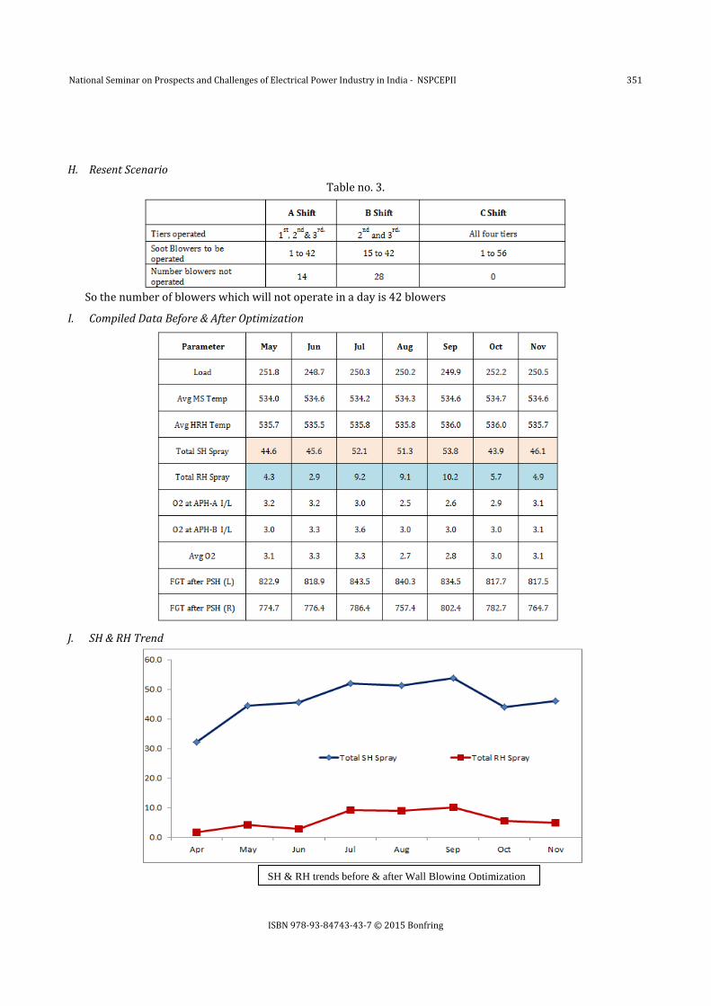
To improve consistency in efficient operation of boiler To reduce steam wastage by identifying those areas of low or no deposits To reduce damage on furnace wall tubes due to excessive blowing The change in SH spray & RH Spray without change in other parameters indicates that the furnace deposits
are increasing. If thesuperheater or reheater sprays increases above a particular level (to be determined for each boiler), operate all wall blowers. These are two basic things to adhere to while optimizing wall blowers.
IV. OPTIMISATION STRATEGY ADOPTED
E. Earlier Operation Of Wall Blower
In every 8-hr shift, wall blowing used to be done once. It takes around 1 hour 30 min for complete blowing. All blowers (1 to 56) were operated at a pressure of about 22 kgf/cm2& temperature of about 240 deg. C.
F. Technique Adopted
There are 56 wall blowers in a boiler furnace wall, the steps for optimization is listed.
Operate all 56 blowers See the effect on superheater spray and note all operating parameters of boiler Wait for the superheater spray to ramp up to the initial level and stay almost steady Wall blow each row - study effect Watch superheater spray drop and regain time The interval between blowers is to be maintained constant Repeat if required each row independently, waiting each time for the spray to reach the original level
with other parameters of boiler remaining constant Repeat the study for two adjacent rows
National Seminar on Prospects and Challenges of Electrical Power Industry in India - NSPCEPII 349
Repeat the study for two alternate rows Repeat the study for blowers in front, rear, left and right sides of furnace walls separately and study the
effect on superheater spray flow. The blowing having the least effect on the superheater spray indicates low or no deposit on the walls. A plot of superheater spray drop when each blower is operated will give a good idea of deposition in that
area Use the photograph of the furnace wall to validate the effectiveness of blowers Decide which blowers can be skipped during blowing as well as the effectiveness of the row
Table no. 1.
The procedure for wall blower operation can be evolved after the study and data analysis for the most
effective way of wall blowing.
The use of heat flux meter by embedding thermopiles at appropriate location in the furnace walls to understand whether the tube in the region is clean or with deposition the operation of the wall blower requirement can be decided.
In the case of fully automated intelligent wall blower system, the need to wall blow each blower is understood from the effective heat flux falling on the tubes. Designers use different methods to establish this.
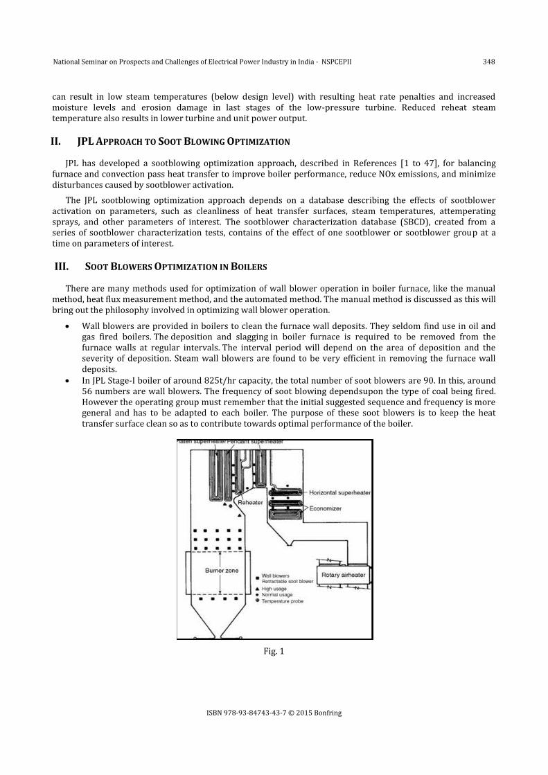
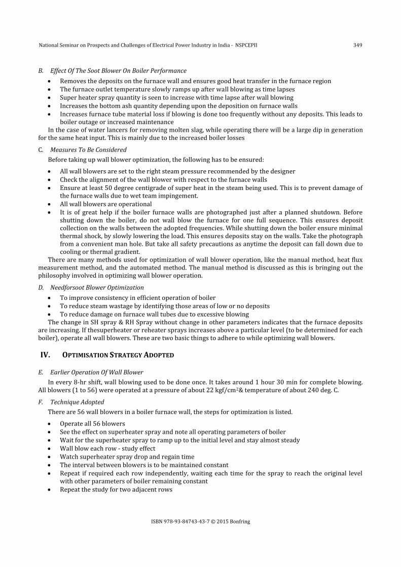
G. Observation
Following are the observations taken under notice with the data collected:
Table no. 2
National Seminar on Prospects and Challenges of Electrical Power Industry in India - NSPCEPII 350
A. Quantity of DM Water Saved Total quantity of steam consumed during wall blowing (1 to 56):- 5 tones i.e. 5000 Kg of steam
=> The steam consumed per blowing is = 5000/ 56 = 89.2 kg of steam
By adopting above mentioned combination amount of steam consumption reduction
= (89 X 14) + (89 X 28) = 3738 kg of steam per day
Steam consumption reduction in a year (taking 97% PLF) = 3738 x 0.97 x 365 = 13, 23,439 kg = 1323 tonnes in a year
DM water cost = 100 Rs per m3 = 100 Rs per tonne
Total cost of DM water lost = 1323 x 100= 132300 Rs = 1.32 Lacs
B. Amount of Heat Energy Saved in terms ofCoal by throttling of steam Steam condition at Super heater header a throttling for supplying steam to wall blowers: - Pr. -165 Kg/cm2 &
Temp. – 420 degree C
Enthalpy of steam = 724 Kcal/kg
Quantity of steam saved = 1323 tonnes
Total savings = 1323 X 724 = 975852000 kcal
Taking coal GCV 3500 kcal/kg, Quantity of coal saved
= 975852000/3500 = 273672 kg = 273.6 tonnes Amount saved = 273672 (assuming cost of coal 1000 Rs per tonne)
= 2.73 lacs Total amount saved = 1.32 +2.73 = 4.05 lacs in a year.
VI. CONCLUSION
A series of upgraded steps at the JPL have been coupled with optimization systems to gain performance benefits in the form of fuel savings, reduced emissions, increased net power generation and improved dispatch capability along with financial saving. The combination of a flexible and capable toolset, application expertise and the power of continuous improvement are now Providing continuous and significant performance benefits to the station.
REFERENCE
[1] 1.Sarunac, N., Romero, C.E., Clements, B., Pomalis, R., Henrikson, J., Cylwa, W.and Luk, J., “Sootblowing Optimization: Part 1 - Methodology, Instrumentationand Determination of Section Cleanliness,” Presented at Combustion Canada 2003 Conference, September 21-24, 2003, Vancouver, BC, Canada.
[2] 2. Sarunac, N., Romero, C.E., Shan, J., Bian, X., Clements, B., Pomalis, R., Henrikson, J., Cylwa, W. and Luk, J., “Sootblowing Optimization: Part 2–Sootblower Characterization and Implementation of an Intelligent Sootblowing Advisor,” Presented at Combustion Canada 2003 Conference, September 21-24, 2003, Vancouver, BC, Canada.
[3] 3. Sarunac, N. and Romero, C., “Sootblowing Optimization and Intelligent [4] Sootblowing,” Presented at 4th Intelligent Sootblowing Workshop, Houston, [5] Texas, March 2002.
National Seminar on Prospects and Challenges of Electrical Power Industry in India - NSPCEPII 352
[6] 4. Sarunac, N., Romero, C. E. and Bilirgen, H., “Optimization of Sootblowing in Utility Boilers,” EPRI Heat Rate Conference, Birmingham, Alabama, January 28- 30, 2003.
[7] 5. Sarunac, N., Romero, C.E. and Levy, E. K., “Combined Optimization for NOx Emissions, Unit Heat Rate and Slagging Control with Coal-Fired Boilers,” 28thInternational technical Conference on Coal Utilization and Fuel Systems, March 9-14 2003, Clearwater, Florida.
[8] 6. Pomalis, R., Clements, B. R. and Abdallah, I. “Ash Monitoring System forLambton Generation Station Unit 3,” CETC Division Report CETC-O-ACT-03-14 (CF), Natural Resources Canada, 2003.
[9] 7. Sarunac, N. and Romero, C.E. “Sootblowing Operation: The Last OptimizationFrontier,” Presented at the 29th International Technical Conference on Coal Utilization & Fuel Systems, Clearwater, Florida, April 18-22, 2004.
[10] 8. Sarunac, N. and Romero, C.E. “Sootblowing Operation: The Last Optimization Frontier,” Presented at the 29th International Technical Conference on Coal Utilization & Fuel Systems, Clearwater, Florida, April 18-22, 2004.
[11] Sarunac, N., Romero, C.E., Bilirgen, H., Bokowski, J. And Cilinski, M., “Comprehensive Approach to Performance Improvement and Emissions Reduction on a 400 MW Tangentially-Fired Boiler: Part 2 –ESP Performance Improvement and Sootblowing Optimization,” Presented at the 30th International Technical Conference on Coal Utilization and Fuel Systems, April 2005, Clearwater, Florida.
[12] Congdon, P., “Control Alternatives for Industrial Boilers,” InTech,December 1981. [13] Walsh, T. J., “Controlling Boiler Efficiency,” Instruments and ControlSystems, January 1981. [14] ANSI/ASME, “PTC 4.1, Steam Generating Units Power Test Codes,”American Society of Mechanical Engineers
(ASME), 1965. [15] Culp, A. W., Jr., Principles of Energy Conversion, New York:McGraw-Hill, 1979, p. 102, pp. 204–207. [16] MacDonald, J. A., “Optimizing Power Boiler Efficiency Calls forHeat Loss Cuts, System Insulation, and
Modifications,” Energy-Tech,April 2004. [17] Shinskey, F. G., Energy Conservation through Control, AcademicPress, 1978. [18] Babcock and Wilcox, Steam: Its Generation and Use, 40th ed., NewYork: Babcock and Wilcox, 1992. [19] NFPA, NFPA-85 — Boiler Combustion Safety, National Fire ProtectionAssociation, 2004. [20] Garton, D., “Water Cannon for Water Wall Cleaning Applications,”EPRI Intelligent Soot Blowing Conference,
December 6–7, 1999. [21] McMahon, J. F., president, Cleveland Controls, verbal communications. [22] Dickey, P. S., “A Study of Damper Characteristics,” Bailey Meter Co.,Reprint No. A8. [23] Jorgensen, R., “Fans,” in Marks Standard Handbook for MechanicalEngineers, 8th Ed., McGraw-Hill, New York,
1978, p. 14.53. [24] Dukelow, S. G., The Control of Boilers, 2nd ed., Research TrianglePark, NC: Instrumentation, Systems, and
Automation Society, 1991. [25] Hurlbert, A. W., “Air Flow Characterization Improves Boiler Effi-ciency,” InTech, March 1978. [26] DeLorenzi, O., Combustion Engineering, Inc., 1967. [27] ANSI/ISA-77.42.01, “Fossil Fuel Power Plant Feedwater ControlSystem: Drum Type,” Instrumentation, Systems,
and AutomationSociety, 1999. [28] Shinskey, F. G., “Taming the Shrink–Swell Dragon,” Control, March2004. [29] Fisher Controls International, Control Valve Sourcebook: Power andSevere Service, Marshalltown, IA: Fisher
Controls International,1990. [30] Miller, H. L. and Stratton, L. R., “Fluid Kinetic Energy as a SelectionCriteria for Control Valves,” American Society
of Mechanical Engineers,Fluids Engineering Division, summer meeting, June 22–26,1997. [31] Shinskey, F. G., Process Control Systems, New York: McGraw-Hill,1979. [32] Latta, C. A., “Methods for Reducing NOx Emissions,” Plant Engineering,September 1998. [33] McDonald, J. A., “Controlling the NOx after the Burn,” Energy-Tech,December 2002. [34] Schwartz, J. R., “Carbon Monoxide Monitoring,” InTech, June 1983. [35] O’Meara, J. E., “Oxygen Trim for Combustion Control,” InTech,March 1979. [36] McFadden, R. W., “Multiparameter Trim in Combustion Control,”InTech, May 1984. [37] American Technical Services, “Boiler Audits,” June 1982. [38] McMahon, J. F., President, Cleveland Controls, verbal communications. [39] Westinghouse Electric Corp., “Oxygen Trim Control,” AD-106-125,Westinghouse Electric Corp., June 1979,
January 1985. [40] Moelback, T., “Advanced Control Superheater Steam Temperatures:An Evaluation Based on Practical
Applications,” Control EngineeringPractice, Vol. 7, 1999, pp. 1–10.
National Seminar on Prospects and Challenges of Electrical Power Industry in India - NSPCEPII 353
[41] Dukelow, S. G., The Control of Boilers, 2nd ed., Research TrianglePark, NC: ISA, 1991. [42] Schieber, J. R., “The Case for Automated Boiler Blowdown,” UniversalInterlock, 1969. [43] Cho, C. H., “Optimum Boiler Allocation,” InTech, October 1978. [44] Wood, A. J., and Wollenberg, B. F., Power Generation, Operation,and Control, 2nd ed., New York: Wiley
Interscience, 1996. [45] Romero, C., Sarunac, N., and Levy, E., “Soot Blowing Optimizationin Coal-Fired Boilers,” Lehigh University Energy
Research CenterEnergy Liaison Program Annual Meeting, 2001. [46] Cheng, X., Kephart, R. W., and Williams, J. J., “Intelligent SootBlower Scheduling for Improved Boiler Operation,”
Proceedings ofISA POWID/EPRI Instrumentation and Control Conference, St.Petersburg, FL, June 1999. [47] Booth, R. C., and Roland, W. B., “Neural Network-Based CombustionOptimization Reduces NOx Emissions while
Improving Performance,”Proceedings of 1998 ASME International Joint Power GenerationConference, Baltimore, MD, 1998.
[48] Lefebvre, C., Lynch, M., and Roland, R., “Application of ProcessLinkReal-Time Optimization System to Cajun Electric Power Cooperative’sBig Cajun II Generating Station,” Proceedings, 1999 InternationalPower-Gen Conference, New Orleans, LA, 1999.
[49] Lipták, B. G., “Save Energy by Optimizing Your Boilers,” InTech,March 1981.
Yashpal Sahu,
Education qualifications:
ME- Mechanical, BIT, Mesra Ranchi
BE-Mechanical, GRKIST, Jabalpur
Certified Energy Auditor
Certfied BOE
Work Exp: 10 yrs 8 months with Jindal Power Limited,
Education: B.Tech in Electrical & Electronics Engineering (EEE)
From Bengal College of Engineering & Technology , Durgapur
PGDC in Thermal Power Plant from NPTI, Guwahati Work Exp: 1. Since Aug 2009 to Jul 2012 as a Desk Operation Engineering (Asst Manager) in Vedanta Aluminium Ltd. , Jharsuguda.
2. Currently working as a CEEPI TEAM (Asst Manager) in Jindal Power Ltd. , Tamnar.
Pooja Agrawal Education: B.Tech in Electrical Engineering (EE)From Indian School of Mines, Dhanbad Work: Currently working as a CEEPI TEAM (Asst Manager) in Jindal Power Ltd. , Tamnar. Cell no: +91 7898902697 Email: [email protected]
National Seminar on Prospects and Challenges of Electrical Power Industry in India - NSPCEPII 355