INSTALLATION GUIDE FOR SP-2110 SP-2110 II2 QI Copyright - refer to title page Page 1 ENU Status : 1-2-0 SP-2110 WCDMA BAND ADJUSTABLE PICO REPEATER INSTALLATION GUIDE The information contained herein is the responsibility of and is approved by the following, to whom all enquiries should be directed in the first instance: Comba Telecom This is an unpublished work the copyright in which vests in Comba International ("Comba"). All rights reserved. The information contained herein is confidential and the property of Comba and is supplied without liability for errors or omissions. No part may be reproduced, disclosed or used except as authorised by contract or other written permission. The copyright and the foregoing restriction on reproduction and use extend to all media in which the information may be embodied.
Transcript
INSTALLATION GUIDE FOR SP-2110
SP-2110 II2 QI Copyright - refer to title page Page 1ENU Status : 1-2-0
SP-2110 WCDMA BAND ADJUSTABLE PICO REPEATER
INSTALLATION GUIDE
The information contained herein is the responsibility of and is approved by the following, to whom all enquiries should be directed in the first instance:
Comba Telecom
This is an unpublished work the copyright in which vests in Comba International ("Comba"). All rights reserved. The information contained herein is confidential and the property of Comba and is supplied without liability for errors or
omissions. No part may be reproduced, disclosed or used except as authorised by contract or other written permission. The copyright and the foregoing restriction on reproduction and use extend to all media in which the information may be embodied.
INSTALLATION GUIDE FOR SP-2110
SP-2110 II2 QI Copyright - refer to title page Page 2ENU Status : 1-2-0
0.2 CONTENTS
Section Page
0.2 CONTENTS ........................................................................................................................... 2 0.3 INDEX TO FIGURES AND TABLES ..................................................................................... 4 0.4 HISTORY ............................................................................................................................... 5 0.5 GLOSSARY OF TERMS ....................................................................................................... 6 0.6 SAFETY NOTICES AND ADMONISHMENTS ...................................................................... 7
1 GENERAL INFORMATION ................................................................................................... 8
2 SYSTEM INTRODUCTION ................................................................................................... 9 2.1 SP-2110 SYSTEM DIAGRAM ............................................................................................... 9 2.2 EQUIPMENT LAYOUT ........................................................................................................ 10 2.3 EQUIPMENT CONSTITUTION ........................................................................................... 11 2.4 KIT OF PARTS .................................................................................................................... 11
6 SYSTEM MAINTENANCE ................................................................................................... 32
7 APPENDICES...................................................................................................................... 33 7.1 APPENDIX A: SERVICING POLICY AND RETURN OF EQUIPMENT ............................. 33 7.2 APPENDIX B: RMA (RETURN MATERIAL AUTHORIZATION) FORM ............................. 34
INSTALLATION GUIDE FOR SP-2110
SP-2110 II2 QI Copyright - refer to title page Page 4ENU Status : 1-2-0
0.3 INDEX TO FIGURES AND TABLES
Figure 1: Top, Front and Side Views of SP-2110 Enclosure .................................................................. 8 Figure 2: SP-2110 System Diagram ....................................................................................................... 9 Figure 3: SP-2110 Internal Layout ........................................................................................................ 10 Figure 4: SP-2110 Wall Mounting ......................................................................................................... 15 Figure 5: Equipment Connectors .......................................................................................................... 17 Figure 6: Location of LEDs ................................................................................................................... 18 Figure 7: Control Panel ......................................................................................................................... 19 Figure 8: ATT Switches ......................................................................................................................... 20 Figure 9: OMT Login ............................................................................................................................ 21 Figure 10: OMT V5.00 Control Panel ................................................................................................... 22 Figure 11: Auto Connection .................................................................................................................. 22 Figure 13: System Information ............................................................................................................. 24 Figure 14: Auto-Read ........................................................................................................................... 24 Figure 15: Switch ................................................................................................................................. 25 Figure 16: Channel NO. ....................................................................................................................... 25 Figure 17: ATT ..................................................................................................................................... 26 Figure 18: Alarm Threshold .................................................................................................................. 26 Figure 19: Power ................................................................................................................................... 26 Figure 20: Gain ..................................................................................................................................... 27 Figure 21: Temperature ........................................................................................................................ 27 Figure 22: Miscellaneous ...................................................................................................................... 27 Figure 24: Equipment ID ...................................................................................................................... 28 Figure 25: Firmware Info. ...................................................................................................................... 29 Figure 26: Equipment Info. .................................................................................................................... 29 Figure 27: Site Info. ............................................................................................................................... 29 Figure 28: System Clock ....................................................................................................................... 30 Figure 29: Comm. Config ...................................................................................................................... 30 Figure 30: Trigger Report ...................................................................................................................... 31 Figure 31: Update Info. ......................................................................................................................... 31 Table 1: Equipment Constitution ........................................................................................................... 11 Table 2: Kit of Parts ............................................................................................................................... 11 Table 3: Repeater Installation Checklist ............................................................................................... 14 Table 4: Antenna Installation Checklist ................................................................................................. 14 Table 5: Equipment connectors ............................................................................................................ 17 Table 6: LEDs Colour and Indication .................................................................................................... 18
INSTALLATION GUIDE FOR SP-2110
SP-2110 II2 QI Copyright - refer to title page Page 5ENU Status : 1-2-0
0.4 HISTORY
Change No. ENU Details Of Change 1 2 3 4
1-0-0 1-1-0 1-1-1 1-2-0
This document First created in Dec 2010. For Generation II2 product. Updated commissioning and OMT part in Aug 2011. Updated external antenna description in page 15 in Sep 2011. Added non-modem config in doc in Oct 2011.
INSTALLATION GUIDE FOR SP-2110
SP-2110 II2 QI Copyright - refer to title page Page 6ENU Status : 1-2-0
0.5 GLOSSARY OF TERMS
Acronym Definition ALC Automatic Level Control ATT Attenuation BS Base Station BTS Base Transceiver Station CDMA Code Division Multiple Access dB Decibel dBm Decibels relative to 1 milliwatt DL DL DPX Duplexer DT Donor Terminal EEPROM Electrically Erasable Programmable Read Only Memory FS Frequency Selector FSA Frequency Selector Amplifier GSM Global System for Mobile Communication Hz Hertz ID Identification LNA Low Noise Amplifier MCU Main Control Unit MHz Megahertz MS Mobile Subscriber MT Mobile Terminal MTBF Mean Time Between Failures NC Normally Closed NF Noise Figure NO Normally Open OMC Operation & Maintenance Center OMT Operation & Maintenance Terminal PA Power Amplifier PLL Phase Locked Loop PSU Power Supply Unit RF Radio Frequency SMA Sub-Miniature A Connector (coaxial cable connector type) UL UL VAC Volts Alternating Current VSWR Voltage Standing Wave Ratio
INSTALLATION GUIDE FOR SP-2110
SP-2110 II2 QI Copyright - refer to title page Page 7ENU Status : 1-2-0
0.6 SAFETY NOTICES AND ADMONISHMENTS
This document contains safety notices in accordance with appropriate standards. In the interests of conformity with the territory standards for the country concerned, the equivalent territorial admonishments are also shown. Any installation, adjustment, maintenance and repair of the equipment must only be carried out by trained, authorized personnel. At all times, personnel must comply with any safety notices and instructions. Specific hazards are indicated by symbol labels on or near the affected parts of the equipment. The labels conform to international standards, are triangular in shape, and are colored black on a yellow background. An informative text label may accompany the symbol label. Hazard labeling is supplemented by safety notices in the appropriate equipment manual. These notices contain additional information on the nature of the hazard and may also specify precautions. Warning: These draw the attention of personnel to hazards which may cause death or injury to the operator or others. Examples of use are cases of high voltage, laser emission, toxic substances, point of high temperature, etc. Alert: These draw the attention of personnel to hazards which may cause damage to the equipment. An example of use is the case of static electricity hazard. Caution notices may also be used in the handbook to draw attention to matters that do not constitute a risk of causing damage to the equipment but where there is a possibility of seriously impairing its performance, e.g. by mishandling or gross maladjustment. Warnings and Cautions within the main text do not incorporate labels and may be in shortened form.
End of section
INSTALLATION GUIDE FOR SP-2110
SP-2110 II2 QI Copyright - refer to title page Page 8ENU Status : 1-2-0
1 GENERAL INFORMATION
SP-2110 is a WCDMA Band Adjustable Pico Repeater (Hereinafter called “system”). This system is used in indoor locations where small-scale signal coverage for metropolitan environment is desired (e.g., hotels, department stores and shopping malls, underground parking lots, convention centres, arenas, etc.) This system is designed for indoor operation in the WCDMA band. Its bi-directional amplifier is used to enhance signal strength in small and medium size areas in a WCDMA network. Besides, its center frequency is adjustable and it’s IF filtering provides superior out-of-band rejection. Characteristics of the SP-2110 repeater are as follows: • Highly integrated design with miniaturized chassis, compact size and light weight. • Equiped with operating status indicator, alarm indicator and downlink input signal level indicators. • DL and UL wideband amplification, fixed bandwidth and center frequency adjustable. • Low noise amplifier improves system noise figure for better voice quality and reduced drop call. • The system gain is compensated automatically according to the temperature variation within the
enclosure, which ensures stable operation under ambient temperature. • Isolation testing and one click smart setup functions for convenience field application. • Local Operation and Maintenance Terminal (OMT): operating status and parameters can be set
or monitored by OMT PC locally. • WCDMA/GSM dual mode modem for remote monitoring through SMS or datalink.
The figure below presents the enclosure layout of SP-2110:
210
140
39.5
Figure 1: Top, Front and Side Views of SP-2110 Enclosure
INSTALLATION GUIDE FOR SP-2110
SP-2110 II2 QI Copyright - refer to title page Page 9ENU Status : 1-2-0
2 SYSTEM INTRODUCTION
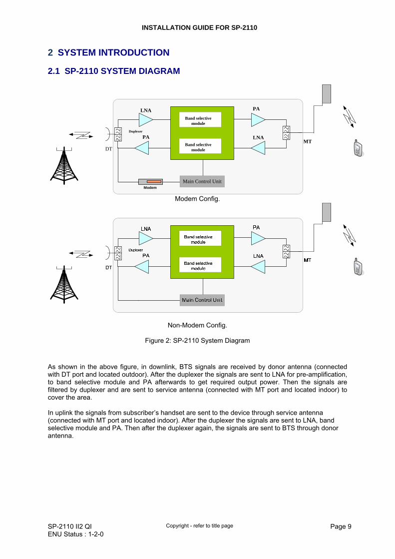
2.1 SP-2110 SYSTEM DIAGRAM
DT
LNA PA
PA LNADuplexer
MT
Band selective module
Band selective module
Main Control UnitModem
Modem Config.
Non-Modem Config.
Figure 2: SP-2110 System Diagram
As shown in the above figure, in downlink, BTS signals are received by donor antenna (connected with DT port and located outdoor). After the duplexer the signals are sent to LNA for pre-amplification, to band selective module and PA afterwards to get required output power. Then the signals are filtered by duplexer and are sent to service antenna (connected with MT port and located indoor) to cover the area. In uplink the signals from subscriber’s handset are sent to the device through service antenna (connected with MT port and located indoor). After the duplexer the signals are sent to LNA, band selective module and PA. Then after the duplexer again, the signals are sent to BTS through donor antenna.
INSTALLATION GUIDE FOR SP-2110
SP-2110 II2 QI Copyright - refer to title page Page 10ENU Status : 1-2-0
2.2 EQUIPMENT LAYOUT
The following figure shows SP-2110 internal layout.
Modem Config.
MT
DT
Power Supply Port
StartATT Switches
RS-232
Non-Modem Config.
Figure 3: SP-2110 Internal Layout
INSTALLATION GUIDE FOR SP-2110
SP-2110 II2 QI Copyright - refer to title page Page 11ENU Status : 1-2-0
2.3 EQUIPMENT CONSTITUTION
SP-2110 consists of the modules described as below:
Identifier Functional Description Modem WCDMA/GSM Modem for remote monitoring and control Li-ion Battery Power supply for Maiin Control Unit in case of power failure Power Supply Port 6VDC Power Supply for repeater Main Control Unit For OMT/OMC remote monitoring and control
RS-232 users can realize the on-line connection between the equipment and OMT through this port
ATT Switches Attenuation setting for non-modem version SP2110 ONLY
Start One click smart setup button, repeater will automatically measure the isolation and set attenuation by clicking this button. This function only available for modem config.
Table 1: Equipment Constitution 2.4 KIT OF PARTS
For the equipement, the following parts are shipped.
SP-2110 II2 QI Copyright - refer to title page Page 12ENU Status : 1-2-0
3 INSTALLATION
3.1 WARNINGS AND ALARTS
Radio Frequency energies There may be situations, particularly the workplace environments adjacent to high-powered RF sources, where recommended limits for safe exposure of human beings to RF energy could be exceeded. In such cases, restrictive measures or actions may be necessary to ensure the safe use of RF energy. High voltage The equipment has been designed and constructed as to prevent as far as reasonably practicable danger. Any activity, such as installation, operation and maintenance, on or near the equipment must be as far as reasonably free from danger. Where there is a risk of damage to electrical systems due to adverse weather, extreme temperatures, wet, corrosive or dirty conditions, flammable or explosive atmosphere, then the system must be suitably installed to avoid such a danger. Protective Earthing Equipment provided for the purpose of protecting individuals from electrical risk must be properly used and maintained. Handling Precautions Precautions should be taken in equipment handling activities including lifting, lowering, pushing, pulling, carrying, moving or holding, or the activities to prevent an object, animal or a person going into the chassis, or the activities when extra efforts are needed such as pulling a lever, or operating power tools. ESD Take necessary precautions when handling ESD-sensitive devices. Assume that all solid-state electronic devices are ESD-sensitive. Do use a grounded wrist strap or the like while working with ESD-sensitive devices. Transport, store, and handle ESD-sensitive devices in static-free environments.
INSTALLATION GUIDE FOR SP-2110
SP-2110 II2 QI Copyright - refer to title page Page 13ENU Status : 1-2-0
3.2 SITE PLANNING CONSIDERATIONS
Site considerations The repeater is designed for indoor installation and operation. Installation location Mounting surface shall be capable of supporting weight of the equipment, allow 1.5Kg for the SP-2110 equipment. Physical location should be able to achieve signal strength of better than -70dBm from the BTS antenna, and the MT antennas should provide the required coverage. Antenna separation For optimal operation, the physical separation of the MT and DT antennas should satisfy the condition for I > GMAX +10dB, where I represents isolation between MT and DT ports. Environmental Humidity has an effect on the reliability of the equipment. It is recommended to install the equipment in location having stable temperature and un-restricted air-flow. SP-2110 equipment has been designed to operate at the temperature range from -20°c to +40°c with relative humidity at ≤85%. Powering (AC mains supply) The external power supply unit provides power to all modules within the chassis. The equipment accepts 6VDC via an external PSU. In order to avoid electromagnetic interference, select the SP-2110 mounting location to minimize interference from electromagnetic sources such as: large electricity powered equipment. Grounding requirement Verify the equipment has been well grounded, this includes antennas and all cables connected. Ensure lightning protection for antennas is properly grounded. Cable routing The RF cables for SP-2110 have SMA (F) connectors; other cable connects the equipment with the external PSU. Manual handling During transportation and installation, take necessary handling precautions to avoid potential physical injury to the installation related personnel and/or damages to the equipment.
INSTALLATION GUIDE FOR SP-2110
SP-2110 II2 QI Copyright - refer to title page Page 14ENU Status : 1-2-0
3.2.1 REPEATER INSTALLATION CHECKLIST
Installation Location Requirement Considerations
AC power supply at each installation location: 100~240VAC, 50/60Hz
Power cord length is 1.5m, use a dedicated AC breaker or fuse circuit, and with good access to an earthing point.
EMC and interference Do not locate near large transformers or motors that may cause electromagnetic interference.
Maintain reasonable distance from chassis to DT, MT antennas Reduction of signal loss in feeder cable
Suitable operating environment -20°C to 40°C, Maximum 85% relative humidity. Avoid direct sun exposure and keep good air cooling environment.
Table 3: Repeater Installation Checklist
3.2.2 ANTENNA INSTALLATION CONSIDERATION
Installation Location Requirement ConsiderationsLocate donor antenna in a site to receive the maximum signals from the desired BTS and to shield the other signals at the same time.
For maximum output power, Maximum input power = Maximum Output Power – Gmax
Line of sight between BTS antenna and donor antenna is required
Isolation of BTS antenna and mobile antenna (I) must be larger than the maximum gain of the repeater in operation.
I > Gmax+ 10dB
Table 4: Antenna Installation Checklist
INSTALLATION GUIDE FOR SP-2110
SP-2110 II2 QI Copyright - refer to title page Page 15ENU Status : 1-2-0
3.3 INSTALLATION PROCEDURES
3.3.1 GOODS INWARDS INSPECTION
This SP-2110 was factory tested, inspected, packed, and delivered to the carrier with utmost care. Do not accept shipment from carrier which shows damage or shortage until the carrier's agent endorses a statement of the irregularity on the face of the carrier's receipt. Without documentary evidence, a claim cannot be processed. Open and check each package against the packing list. For any shortage, contact Comba Telecom Systems. Do not remove items from packing materials until installation. This equipment can be either installed on wall or laid on a table horizontally. 3.3.2 WAL MOUNTING
Screw ST4x30
Wall Plug
Figure 4: SP-2110 Wall Mounting
3.3.3 TOOLS
See Appendix for a full list of tools required for installation and maintenance. 3.3.4 PREPARATION
SP-2110 equipment: Mounting surface of wall or table capable of supporting chassis’ weight: ≥1.5kg. Power outlet within 1.5m.
INSTALLATION GUIDE FOR SP-2110
SP-2110 II2 QI Copyright - refer to title page Page 16ENU Status : 1-2-0
3.3.5 EXTERNAL ANTENNA CONNECTION
• Connect the MT port with onmi-antenna or distributed antenna system. 3.3.6 DRIP-LOOP
Comba recommends that every horizontal cable entry to the equipment forms a 'U' before its entry to the equipment. Any accumulated water on the cable will drip down at the bottom of the loop and will not climb up to the equipment. 3.3.7 EQUIPMENT CONNECTIONS
Service voltage connection The repeater accepts 220/110VAC power. The recommended DC connection is rated at 6VDC and has three connections to include earth. The cable length is around 1.5m. External RF connection Connection of feeder cables are as below: donor antenna cable → DT port Connecting to mobile antenna: mobile antenna cable → MT port
INSTALLATION GUIDE FOR SP-2110
SP-2110 II2 QI Copyright - refer to title page Page 17ENU Status : 1-2-0
3.4 EQUIPMENT CONNECTORS
The SP-2110 connectors are shown as below.
MT
DT
Power
Figure 5: Equipment Connectors
Identifier Descriptions
DT N-Female connector for connection to donor antenna
MT N-Female connector for connection to service antenna
Power1 The input port for AC adaptor
Table 5: Equipment connectors
End of section
1 The voltage identification is a variant due to electricity system diversity of global regions. The power cable gland might be identified for AC 220V, AC 110V, AC 220V/110V, DC -48V, or DC +24V respectively. Please refer to specific product or contact local sales if any doubt.
INSTALLATION GUIDE FOR SP-2110
SP-2110 II2 QI Copyright - refer to title page Page 18ENU Status : 1-2-0
4 COMMISSIONING
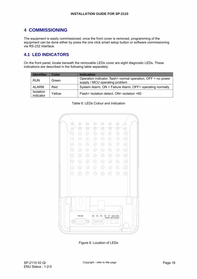
The equipment is easily commissioned, once the front cover is removed, programming of the equipment can be done either by press the one click smart setup button or software commissioning via RS-232 interface. 4.1 LED INDICATORS
On the front panel, locate beneath the removable LEDs cover are eight diagnostic LEDs. These indications are described in the following table separately:
Identifier Color Indication
RUN Green Operation indicator. flash= normal operation, OFF = no power supply / MCU operating problem
ALARM Red System Alarm, ON = Failure Alarm, OFF= operating normally Isolation indicator Yellow Flash= Isolation detect, ON= isolation <60
Table 6: LEDs Colour and Indication
ALM RUNP1P2P3ANT IN/OUTSTART
P4P5RS-232
Figure 6: Location of LEDs
INSTALLATION GUIDE FOR SP-2110
SP-2110 II2 QI Copyright - refer to title page Page 19ENU Status : 1-2-0
P P P P P
Isolation Indicator Figure 7: Control Panel
Power level indicator group, the indicator group is used to show DL input power intensity.
indicator Power Indicators (ON) Power range none <-70dBm
P5 -70dBm to -61dBm
P4~P5 -60dBm to -51dBm
P3~P5 -50dBm to -41dBm
P2~P5 -40dBm to -31dBm
P1~P5 ≥-30dBm
P1 P2 P3 P4 P5
P1 P2 P3 P4 P5
P1 P2 P3 P4 P5
P1 P2 P3 P4 P5
P1 P2 P3 P4 P5
P1 P2 P3 P4 P5
INSTALLATION GUIDE FOR SP-2110
SP-2110 II2 QI Copyright - refer to title page Page 20ENU Status : 1-2-0
4.2 ISOLATION DETECTION
Use OMT to conduct on-line connection. Turn on the isolation test switch to detect the isolation between service antenna and donor antenna. The yellow indicator will flash about 20 seconds and the isolation value will be showed on OMT. The isolation indicator will be on when the isolation value is lower than 60dB and repeater will detect the isolation again within 24 hours. When isolation indicator is on, user is suggested to adjust the antenna in time to increase isolation. 4.3 AUTO COMMISSION
After the power on, press one click smart setup switch (press for about 2 seconds), the yellow indicator begins to flash, means the device automatically detect the isolation and adjusting gains. The yellow indicator extinguish shows the completion of installation. 4.4 ATT SWITCHES
NOTE: ATT Switches are ONLY available for non-modem version SP2110. For SP2110 with remote monitoring function, the ATT swiches are invalid.
Figure 8: ATT Switches
ATT switches are used for attenuation setting for non-modem version SP2110, the switches from left to right are labeled as “1”, “2”, “3”, “4”, “5”, “6”. Switch “6” is the main control switch of the ATT switches. When dial “ON”, meaning ATT switches function is ON, and software ATT is invalid. When the switch is “OFF”, ATT switches function is OFF, user can set ATT through OMT software ONLY. Switch “1” to “5” control DL and UL ATT simultaneously. Switch “1” equals 1dB attenuation. Switch “2” is 2dB attenuation. Switch “3” is 4dB attenuation. Switch “4” is 8dB attenuation and switch “5” is 16dB attenuation. When switch is dial “ON”, switches’ corresponding attenuation is valid, otherwise is zero. The valid attenuation is the sum of the 5 switches, maximum 20dB. e.g.: switch “1” and “4” are “ON”, DL and UL ATT equal 1dB+8dB=9dB.
INSTALLATION GUIDE FOR SP-2110
SP-2110 II2 QI Copyright - refer to title page Page 21ENU Status : 1-2-0
5 OMT
This section is to be read in conjunction with the OMT document. The equipment can be monitored and controlled by OMT software running on a local PC with serial connection to the equipment. Note: If the items in the OMT window are displayed in grey, these can not be set or monitored. OMT software is based on Windows operation system which includes configuration management, maintenance management, RF information, network information, setup and responding of equipment operating status. 5.1 LOCAL CONNECTION TO OMT
After installing OMT software on the PC, connection to the equipment can be done locally or remotely. 5.1.1 OMT LOGIN
When starting OMT, the following figure will show.
Figure 9: OMT Login
The default password is 888888.User can change it in the [set password] window.
INSTALLATION GUIDE FOR SP-2110
SP-2110 II2 QI Copyright - refer to title page Page 22ENU Status : 1-2-0
5.1.2 OMT CONTROL PANEL
Click “Auto Connection” in the pop up window:
Figure 10: OMT V5.00 Control Panel
5.1.3 AUTO CONNECTION
In the following figure, choose “Local Connection via RS232”, select the proper serial port number and then click [ONLINE] to connect.
Figure 11: Auto Connection
INSTALLATION GUIDE FOR SP-2110
SP-2110 II2 QI Copyright - refer to title page Page 23ENU Status : 1-2-0
5.2 OMT CONFIGURATION
After entering the OMT main screen, click the “Connect” button on the toolbar, to connect the equipment to the OMT. Successful connection will be indicated by a message “Online Ok” and equipment parameters can be read and/or set. Users can configure the parameters, and then offset the parameters according to desired coverage level and interference to other BTS signals. OMT parameters include: Common Information, RF Information, Alarm Information, and Properties Information.
Figure 12: Main Window
INSTALLATION GUIDE FOR SP-2110
SP-2110 II2 QI Copyright - refer to title page Page 24ENU Status : 1-2-0
5.3 DESCRIPTION OF PARAMETERS
5.3.1 COMMON INFORMAITON
System Information Click on [System Info.] within Equipment Information, system information will be displayed in the right interface of the OMT screen.
Figure 13: System Information
Auto-Read Normally customer can set which parameters to be read automatically at a particular time interval. Note: [Auto-Read] is under developed and unavailable in current platform. Click on the [Auto-Read] node in the right interface the parameters will be displayed in the right interface. Select the desired parameters and click [Save] button. Input a number in the time interval field and click the adjacent [Save] button to admit the setting. Example: If the time interval is 3 seconds, then the selected alarm parameters will be read automatically every 3-second.
Figure 14: Auto-Read
INSTALLATION GUIDE FOR SP-2110
SP-2110 II2 QI Copyright - refer to title page Page 25ENU Status : 1-2-0
5.4 RF PARAMETER
It is recommended to configure the following RF parameters for the first installation. 5.4.1 SWITCH
Switch is to enable/disable power for internal modules. When user checks and sets non-RF parameters, such as checking physical antenna connection, switching off will disable equipment power temporarily to protect PA in operation. By configuring the “Isolation Test ON/OFF” to ON, the repeater will automatically measure the isolation between Donor antenna and Service antenna, the value can be read in “Miscellaneous”. After the measure is done, the status will automatically switch to “OFF”.
Figure 15: Switch
Config: Select the required state in setting columns of RF information window for RF switch, then press [Enter] or [Config] button to finish the configuration operation. 5.4.2 CHANNEL NO.
Channel No. includes DL Center Channel No. and UL Freq Channel No.
Figure 16: Channel NO.
INSTALLATION GUIDE FOR SP-2110
SP-2110 II2 QI Copyright - refer to title page Page 26ENU Status : 1-2-0
5.4.3 ATT
ATT adjustment includes UL/DL ATT adjustment. The purpose of adjusting the ATT is to adjust system gain.
Figure 17: ATT
Config: Select the required value in setting columns of RF information window for ATT, and press [Enter] or [Config] button to finish the configuration operation. 5.4.4 ALARM THRESHOLD
Users can set alarm threshold according to the specific situation. If the measured value is lower than the threshold lower limit or more than the threshold upper limit, the appropriate alarm will be generated.
Figure 18: Alarm Threshold
5.4.5 POWER
Power is referring to the reading of downlink input/output power
Figure 19: Power
INSTALLATION GUIDE FOR SP-2110
SP-2110 II2 QI Copyright - refer to title page Page 27ENU Status : 1-2-0
5.4.6 GAIN
Figure 20: Gain
Rating Gain: be set before delivery. Comba recommends no change of rating gain value. Gain: User can set according to the real application. 5.4.7 TEMPERATURE
Figure 21: Temperature
5.4.8 MISCELLANEOUS
Figure 22: Miscellaneous
INSTALLATION GUIDE FOR SP-2110
SP-2110 II2 QI Copyright - refer to title page Page 28ENU Status : 1-2-0
5.5 ALARM INFO.
5.5.1 MASTER ALARM
Users should first tick the Enable column to enable the status update function. OMT will not check the status of the items which are disabled.
Figure 23: Master Alarm
5.6 PROPERTIES INFO.
5.6.1 EQUIPMENT ID
Equipment ID is to be configured after local commission has been completed, which includes Site ID, and Site Sub ID.
Figure 24: Equipment ID
See the table below for configuration details of each parameter.
Item Description Site ID Site ID is the unique equipment identification. It is a hexadecimal string of
eight characters in the range of [00000000~FFFFFFFF]. e.g. 00000000 Site Sub ID Site Sub ID is used for Master-Slave System. It is the unique identification of
each Master/ Slave Unit and is a hexadecimal string of two characters in the range of [00~FF]. For the system located with single equipment, the Site Sub ID should be FF. For Master-Slave system, the Site Sub ID for Master Unit is 00, and the Site Sub ID for each Slave Unit is represented in the range of [01~FE] in
INSTALLATION GUIDE FOR SP-2110
SP-2110 II2 QI Copyright - refer to title page Page 29ENU Status : 1-2-0
ascending order. e.g. Master Site ID: 00, Slave Site ID: 01 5.6.2 FIRMWARE INFO.
Figure 25: Firmware Info.
5.6.3 EQUIPMENT INFO.
Figure 26: Equipment Info.
5.6.4 SITE LOCATION
Figure 27: Site Info.
[Site Location]: input the current longitude and latitude in the blank.
INSTALLATION GUIDE FOR SP-2110
SP-2110 II2 QI Copyright - refer to title page Page 30ENU Status : 1-2-0
5.6.5 SYSTEM CLOCK
Figure 28: System Clock
[System Clock]: it shows the current time/date information. It is settable.
5.6.6 COMM. CONFIG
If the equipment is to be monitored by OMC software over wireless GSM / CDMA network, users must finish the [Comm. Config.] in the next step. The Comm. Config information requires to be manually entered by users after successful connection to the equipment.
Figure 29: Comm. Config
See the table below for configuration details of each parameter.
Item Description
Phone No. This is designed for authentication purpose when remote connection via modem is required. It is the phone number to dial the equipment. Only the phone number pre-defined in this field, will it be allowed to dial the equipment. It is required to manually enter the phone number. Up to 5 phone numbers are allowed. The use of phone number authentication can avoid unauthorized use of the OMT. In addition, it can prevent the equipment receiving piles of spam short messages, thus help the operator greatly reduce the cost.
Report Config The Report No. is the SIM card number of the modem built into the OMC Server computer. The equipment will send alarm SMS to this number.
INSTALLATION GUIDE FOR SP-2110
SP-2110 II2 QI Copyright - refer to title page Page 31ENU Status : 1-2-0
If remote communication is needed via modem, users have to enable SMS mode and set the report phone No. by entering the SIM card number of the equipment built-in modem.
SMSC No. It specifies the SMS centre. Users have to set the service No. of SMSC for the first installation, so that the alarms can be sent to OMC.
5.6.7 TRIGGER REPORT
Figure 30: Trigger Report
5.6.8 UPDATE INFO.
Figure 31: Update Info.
End of section
INSTALLATION GUIDE FOR SP-2110
SP-2110 II2 QI Copyright - refer to title page Page 32ENU Status : 1-2-0
6 SYSTEM MAINTENANCE
The SP-2110 repeater is designed for trouble free operation and generally does not need maintenance. Maintenance activities should only be carried out by trained personnel. During operation, if the LED “ALARM” is generated ON, first check the AC power cable and verify AC mains supply is normal. Then disconnect the DT signals, if it is still alarming, cut and reconnect the power supply and recheck as above. In this way, if the “ALARM” is still ON and the signal coverage is unavailable, contact Comba Telecom System. Periodic inspection of the repeater equipment(s) is recommended, the recommended tasks includes:
Measurement of the return loss of the feeder system Verify the direction and position of antennas. Re-align if necessary. Make sure the cable gland and sealing on the RF cable connectors are not damaged. Inspect and record operation status, the diagnostic LEDs and the dial switches. Verify the actual coverage effects are as good as expected Verify lightning and grounding protection is in good condition.
End of section
INSTALLATION GUIDE FOR SP-2110
SP-2110 II2 QI Copyright - refer to title page Page 33ENU Status : 1-2-0
7 APPENDICES
7.1 APPENDIX A: SERVICING POLICY AND RETURN OF EQUIPMENT
The repair of individual units and modules of this equipment is not considered practicable without factory facilities. It is, therefore, the policy of Comba whereby faulty units or modules are returned to the local agent for repair. To enable an efficient, prompt after sales service to be provided for the diagnosis, repair and return of any faulty equipment, please comply with the following requirements. Items to be sent for repair should be packaged so as to provide both electrostatic and physical protection and a Repair Material Authorization (RMA) should be completed giving the required information. A sample RMA form is provided in Appendix. This request must be included with the item for repair. Items for repair should be sent to the nearest Comba office: COMBA TELECOM LTD. Hong Kong Office Address: 611 East Wing, No. 8 Science Park West Avenue, Hong Kong Science Park, Tai Po, Hong


![Scientific Programming [24pt] Lecture A08 Numpydisi.unitn.it/~montreso/sp/slides/A08-numpy.pdf · Alberto Montresor (UniTN) SP - Numpy 2018/10/25 37 / 43. Matplotlib Example4 /2 0](https://static.documents.pub/doc/80x56/5c6ca48b09d3f247048c770c/scientific-programming-24pt-lecture-a08-montresospslidesa08-numpypdf-alberto.jpg)

