Page 1
Space Optimisation and Space Optimisation+
Rev 2.30 December 20th 2017
1 Overview
Space Optimisation is a set of tools available to all Linn DS, DSM and Exakt system owners that allow
optimisation of the interaction between the customers’ loudspeakers and room. Space Optimisation
is accessed and controlled through Konfig.
Before commencing optimisation please ensure that both your DS/DSM and Konfig are updated to
the latest software version (https://www.linn.co.uk/software).
Space Optimisation may be applied to all external inputs of Linn DSM products. Space Optimisation
is applied to the Exakt outputs and the analogue outputs. The SPDIF/TOSLINK, HDMI & headphone
outputs will NOT output Space Optimised audio, these outputs pass the unprocessed audio feed.
Significant changes have been made to the application of Space Optimisation in Konfig 4.33. If you
have systems optimised using earlier versions of Konfig (4.32 or lower) guidance on importing and
applying these optimisations with the new process, along with clarification of the general changes, is
presented in section2.
This document details the basic method for applying Space Optimisation on a Linn DS or DSM, or
Space Optimisation+ on a Linn Exakt system, see section 3.
Set-up of Space Optimisation+ for surround systems is presented in section 4.
More advanced set-up information is presented in section 5, Advanced Space Optimisation.
Konfig allows Space Optimisation set-ups to be saved on a local hard drive and subsequently
exported to alternate locations. Irrespective of saved or exported set-ups it is strongly
recommended that a written note is taken of all relevant dimensions, along with detail of the final
optimisation filters. This ‘hard copy’ should then be stored in the customers file.
Page 2
2
Contents
1 Overview.......................................................................................................................................... 1
2 Significant changes to Space Optimisation within Konfig ............................................................... 4
2.1 Speaker selection .................................................................................................................... 4
2.1.1 Disable analogue speakers for stereo Exakt systems ...................................................... 6
2.2 Importing a previous optimisation .......................................................................................... 7
2.3 Why do I get more room mode filters than before? ............................................................... 8
3 Space Optimisation and Space Optimisation+ set-up ..................................................................... 9
3.1 Install the loudspeakers using the Tune-dem ......................................................................... 9
3.2 Selecting your system and speakers in Konfig ........................................................................ 9
3.2.1 Analogue system ............................................................................................................. 9
3.2.2 Exakt system .................................................................................................................. 13
3.3 Turn on Space Optimisation .................................................................................................. 14
3.3.1 Create a new Optimisation ............................................................................................ 15
3.3.2 Import the current system optimisation ....................................................................... 16
3.3.3 Open an existing optimisation....................................................................................... 16
3.4 Entering you room information in Konfig ............................................................................. 17
3.4.1 Enter room dimensions ................................................................................................. 17
3.4.2 Specify room construction and features ....................................................................... 17
3.5 Enter listening position.......................................................................................................... 19
3.6 Enter loudspeaker positions .................................................................................................. 19
3.6.2 Practical position ........................................................................................................... 20
3.6.3 The Virtual Tune-Dem ................................................................................................... 21
3.7 Additional Subwoofers .......................................................................................................... 21
3.8 Optimise and Apply ............................................................................................................... 22
3.9 Storage of Space Optimisation set-ups ................................................................................. 24
3.9.1 Saving your Space Optimisation .................................................................................... 24
3.9.2 Loading Space Optimisation .......................................................................................... 25
3.9.3 Import and Export ......................................................................................................... 26
4 Setting up Space Optimisation+ for Exakt Surround systems ....................................................... 28
4.1 Assigning speakers within a surround system....................................................................... 28
4.1.1 Full Exakt surround system ........................................................................................... 29
4.1.2 Mixed Exakt and Analogue surround system ................................................................ 30
4.1.3 Subwoofer assignment .................................................................................................. 31
4.2 Set-up Space Optimisation+ .................................................................................................. 33
4.3 Further tuning of the Space Optimisation+ surround set-up ................................................ 34
4.3.1 Manual adjustment of the calculated room mode filters ............................................. 36
Page 3
3
5 Advanced set-up for Space Optimisation and Space Optimisation+ ............................................ 38
5.1 Room modes ......................................................................................................................... 38
5.1.1 Basic assumptions used for calculations of room modes ............................................. 38
5.1.2 How room mode filters are displayed and adjusted ..................................................... 39
5.2 Improving the estimated room mode optimisation using Tune-dem ................................... 44
5.2.1 Room mode filter validity .............................................................................................. 44
5.2.2 Adjusting room mode filters for best sonic performance ............................................. 45
5.3 Additional filtering capability ................................................................................................ 46
5.3.1 Bass and Treble shelves ................................................................................................. 46
5.3.2 Custom filters ................................................................................................................ 47
5.4 Simplifying room dimensions ................................................................................................ 48
5.4.1 Simplifying a room to rectangular dimensions ............................................................. 48
5.5 Approach for rooms which may not be simplified ................................................................ 50
5.5.1 Example room 4, L-shaped ............................................................................................ 51
5.5.2 Example rooms 5, 6 and 7, non-modal rooms .............................................................. 54
Page 4
4
2 Significant changes to Space Optimisation within Konfig
This section details the more significant changes to the application of Space Optimisation and Space
Optimisation+ within Konfig.
In instances where a DS or DSM was previously running an analogue system and the customer has
upgraded to Exakt there is a requirement to de-select the original speakers from the analogue output
channels. This is detailed in section 2.1.1.
In instances where a system has previously been optimised and the original optimisation is imported
some confusion may arise, details are presented in section 2.2.
The new room mode optimisation algorithm will often produce more optimisation filters for a given
room that was seen from earlier versions of Space Optimisation. This is to be expected, the reasons
are detailed in section 2.3.
2.1 Speaker selection
In previous versions of Space Optimisation the selection of connected analogue speakers was
performed as part of the room definition stage (‘CHANGE ROOM INFO’ within Space Optimisation).
Speaker selection is now performed in a separate tab and must be completed before Space
Optimisation can be accessed.
If you select the Space Optimisation tab with no speakers selected you will see the message:
Go to the ‘Speakers’ tab and for each speaker click on ‘ENABLE OPTIMISATION’, you will then be
prompted to selected the manufacturer and model of your loudspeakers.
Page 5
5
The speakers will automatically assign channels ‘LEFT’ and ‘RIGHT’, click ‘APPLY’ and after a moment
you will see the message ‘Updates successfully applied’.
Once the analogue speakers have been selected they will automatically appear in the Space
Optimisation set-up.
Page 6
6
2.1.1 Disable analogue speakers for stereo Exakt systems
If a system is being upgraded to Exakt, either with integrated Exakt speakers or an Exaktbox, you will
need to de-select the previously assigned speakers for the analogue outputs. If this operation is not
performed two sets of loudspeakers will be introduced to the Space Optimisation model.
Click on the ‘Exakt’ tab as normal when assigning Exakt integrated loudspeakers or Exaktboxes.
De-select the speakers assigned to the analogue channels by clicking on ‘CLEAR’ for both left and
right speakers.
Page 7
7
If using an Exaktbox, assign the speakers as normal. Integrated Exakt speakers will automatically
populate. Assign the Exakt speakers as left and right and click on ‘APPLY’. Space Optimisation+ will
now show a single pair of speakers.
2.2 Importing a previous optimisation
Optimisations made previously can be imported into the new Space Optimisation and can be made
to function as expected but care must be taken to ensure they do.
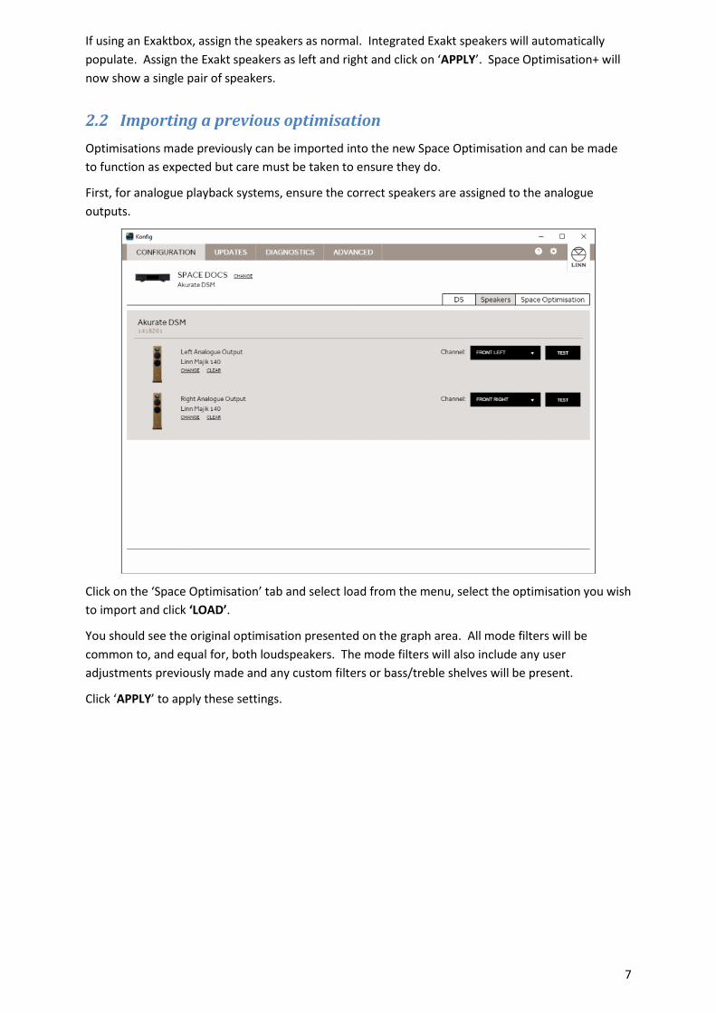
First, for analogue playback systems, ensure the correct speakers are assigned to the analogue
outputs.
Click on the ‘Space Optimisation’ tab and select load from the menu, select the optimisation you wish
to import and click ‘LOAD’.
You should see the original optimisation presented on the graph area. All mode filters will be
common to, and equal for, both loudspeakers. The mode filters will also include any user
adjustments previously made and any custom filters or bass/treble shelves will be present.
Click ‘APPLY’ to apply these settings.
Page 8
8
DO NOT enter the room set-up (‘CHANGE ROOM INFO’), DO NOT press ‘OPTIMISE’. Doing so will
replace the imported mode filters with a newly calculated set of optimisation filters based on the
new optimisation algorithm.
2.3 Why do I get more room mode filters than before?
In earlier versions of Space Optimisation low frequencies were assumed to be mono. As a result both
loudspeakers (the stereo pair) were included in a single room mode optimisation calculation. The
new algorithm does not apply this assumption; each speaker is now treated independently by the
room mode optimisation algorithm.
When a room is acoustically energised at multiple locations with the same signal, depending on the
location of the energising sources many modes will effectively cancel themselves out. A stereo
system, supplied with a mono bass signal, which is set-up symmetrically within a room, will produce
relatively few room modes. Axial width modes (those relating only to the width of the room) will
often cancel, tangential and oblique modes which include the width of the room may also be
significantly reduced in their intensity.
As the new algorithm now calculates the modal optimisation for each individual loudspeaker you will
see more correction filters being applied. Whilst the apparent complexity of the solution may seem
daunting, the benefit of this approach is quite audible, and the amount of post optimisation
modification of the room mode filters is significantly reduced. As the output of each individual
speaker is now pre-optimised to account for the room interaction the perceived stereo balance will
be better, especially for non-symmetrical set-ups.
Page 9
9
3 Space Optimisation and Space Optimisation+ set-up
3.1 Install the loudspeakers using the Tune-dem
Decide along which axis of the room the loudspeakers should be installed. Use the Tune-dem
method to find the ‘ideal’ location for the loudspeakers which gives the best sonic performance.
Correct identification of the ideal loudspeaker position is essential if the full potential of both your hi-
fi system and Space Optimisation is to be achieved.
If you are unsure of how find the ideal location for your loudspeakers then contact your expert Linn
retailer.
3.2 Selecting your system and speakers in Konfig
Before Space Optimisation can be applied to your system Konfig must be informed of the speakers
being used in your system. Making this selection informs Konfig of the physical and acoustical
attributes of your loudspeakers. This information is used by Space Optimisation for calculation of
room modes and placement optimisation. In Space Optimisation+ the information is also used to set
the individual drive unit delays to ensure coincident arrival of the music signal from each drive unit.
This process differs between conventional analogue systems, and Exakt systems. The differences are
detailed in the sections below.
Open Konfig and select the DS/DSM or Exakt system to be optimised. You will notice three tabs to
the top right of the screen.
3.2.1 Analogue system
Open Konfig and select the DS/DSM system to be optimised. You will notice three tabs to the top
right of the screen; DS, Speakers and Space Optimisation.
Page 10
10
Click on the ‘Speakers’ tab, you will see the screen below
Click on ‘ENABLE OPTIMISATION’ for either speaker to select the make and model of your
loudspeakers. Select the manufacturer of your loudspeakers, then click ‘NEXT’.
Page 11
11
If the manufacturer of your loudspeakers does not appear in the selection you should select ‘other’
from the end of the list.
Select your loudspeaker model and click the ‘SELECT’ button.
Loudspeakers which have been measured for Space Optimisation by Linn are indicated by a symbol in
the top right corner. If your loudspeaker model is not selectable you should select ‘Other’ from the end of
the list. Any model which has yet to be measured will raise the message below:
Page 12
12
If you selected ‘Other’ for either the loudspeaker manufacturer or model you will be requested to tell us
about your speaker:
You will need to repeat this operation for both left and right loudspeakers.
Page 13
13
3.2.2 Exakt system
A DS, DSM or Exakt DSM connected to an Exakt system will show the tabs: DS, Exakt and Space
Optimisation+.
Click the ‘EXAKT’ tab.
Page 14
14
If your loudspeakers contain integrated Exakt amplifier modules this page will automatically
populate. You will need to assign the speakers to left and right.
If you are using an Exaktbox based system you will need to select the loudspeakers you have
attached, and enter their serial numbers before you can assign the speakers to the appropriate
playback channel.
If you are using an Exakt DSM you will see only the Integrated Exakt loudspeakers or Exaktboxes
connected to the device over ExaktLink.
For all other DS or DSM sources you will also see connection options for left and right analogue
outputs. For a stereo Exakt system any speakers showing on the left and right analogue outputs
should be removed by clicking on ‘CLEAR’ for each output.
3.3 Turn on Space Optimisation
Click the ‘Space Optimisation’ or ‘Space Optimisation+’ tab. If you DS or DSM has never had Space
Optimisation applied you will see the screen below.
If the system has previously been optimised by another user (the current settings are not on your
computer) you will see the screen below:
Page 15
15
The three possible selections are described below.
3.3.1 Create a new Optimisation
This allows the user to create a new system optimisation from scratch.
Clicking on the ‘Create a new optimisation’ button will bring up the screen below
Page 16
16
3.3.2 Import the current system optimisation
This will tell you if there is already a Space Optimisation within system, but it is not recognised by
your installation of Konfig. For example, you are inspecting another users system. Select this and
Konfig will prompt you to enter a name for this optimisation for saving later.
Once you have named the optimisation you will be prompted to turn on Space Optimisation by
clicking the ‘TURN ON’ button.
3.3.3 Open an existing optimisation
This allows you to recall a system setup that has been saved on that PC/MAC
Page 17
17
3.4 Entering you room information in Konfig
Click on ‘CHANGE ROOM INFO’ to enter details about the room, speaker and listener positions. The
frequency response graph and the associated filter selection and control buttons will be replaced by a
scrolling data entry page as shown below.
3.4.1 Enter room dimensions
Carefully measure your room and enter the dimensions into Konfig. All measurements should be given in
metres. As you enter the dimensions Konfig will adjust the room image on the left of the screen to reflect
changes.
The room mode algorithm assumes a rectilinear room shape, if your room is not a simple rectangular shape
you will need to make some approximations. For advice on how to simplify complex room geometries, see
section 5.3 in Advanced set-up for Space Optimisation and Space Optimisation+.
3.4.2 Specify room construction and features
Once the room dimensions are entered you will need to specify the construction type for each
surface in the room along with any features such as windows and doors.
Starting with front wall, click the drop down list adjacent to ‘Construction Type’. Select the most
appropriate description of the construction of the wall.
‘CONCRETE’ describes any solid or very heavy wall construction including brick, blockwork or stone.
‘PARTITION’ describes any flexible or lightweight construction such as wooden studwork and
plasterboard walls.
‘UNKNOWN’ provides a coefficient to the room mode algorithm halfway between the ‘CONCRETE’
and ‘PARTITION’ settings. Use this selection if the construction is actually unknown. The selection is
also useful where you believe the construction to lie between solid and lightweight construction
methods, for example this could be selected for drywall construction (plasterboard cement mounted
to a solid wall).
Page 18
18
If the wall has any features, such as windows or doors, click the ‘ADD FEATURE’ button.
Select the feature type and enter the width and height of the feature. If you need to add more
features, click on the ‘ADD FEATURE’ button. To delete a feature click the ‘DELETE’ text adjacent to
the feature heading.
Repeat the above steps for each of the six surfaces in the room.
Page 19
19
3.5 Enter listening position
Enter the distance of your listening position from the front and left walls. Remember that the
distances must be entered in metres.
3.6 Enter loudspeaker positions
Measure the distance from your loudspeaker to the front and side walls and enter the dimensions
into Konfig.
The ‘IDEAL SPEAKER’ position fields MUST be entered otherwise Space Optimisation will not work.
Konfig will provide the position on your loudspeaker from which the distances must be taken.
3.6.1.1 Point source modelling
If your loudspeaker has not been measured by Linn for Space Optimisation you will be prompted to
enter the location of the lowest frequency drive unit relative to the front and side walls. If your
loudspeaker has multiple low frequency drive units you should take an approximate average position
for the drive units.
Page 20
20
3.6.2 Practical position
If the ‘Ideal position’, where the loudspeakers offer their best sonic performance in your listening
position, is not suitable due to other domestic constraints then move the loudspeakers to a more
practical location and re-measure to the front and side walls.
Check the ‘Practical Position’ tick-box and enter new distances into Konfig. Repeat for the right
loudspeaker.
Page 21
21
3.6.3 The Virtual Tune-Dem
In some cases, especially for in-wall or in-ceiling speakers and surround systems, it may be impossible
or impractical to find the ideal position by physically relocating the speakers. In such cases the
placement optimisation feature in Space Optimisation can be utilised to perform a ‘Virtual Tune-
dem’ on the loudspeakers.
To perform a ‘Virtual Tune-dem’, select the ‘Practical Position’ checkbox and enter the required
speaker position into Konfig as the practical position. Adjust the ‘Ideal Position’ settings to reflect
the changes you would make if you were physically moving the speakers. Continue to adjust the
ideal positions using Tune-dem to establish the ‘Virtual’ ideal position.
3.7 Additional Subwoofers
If you have any Subwoofers to add click the ‘ADD SUBWOOFERS’ button.
With conventional analogue front left/right loudspeakers you connect the sub to the Linn DS/DSM
front left or right analogue output sockets.
In an Exakt system you should to use an Exaktbox-sub for the sub-woofer connection.
Enter the location of the subwoofer(s).
Page 22
22
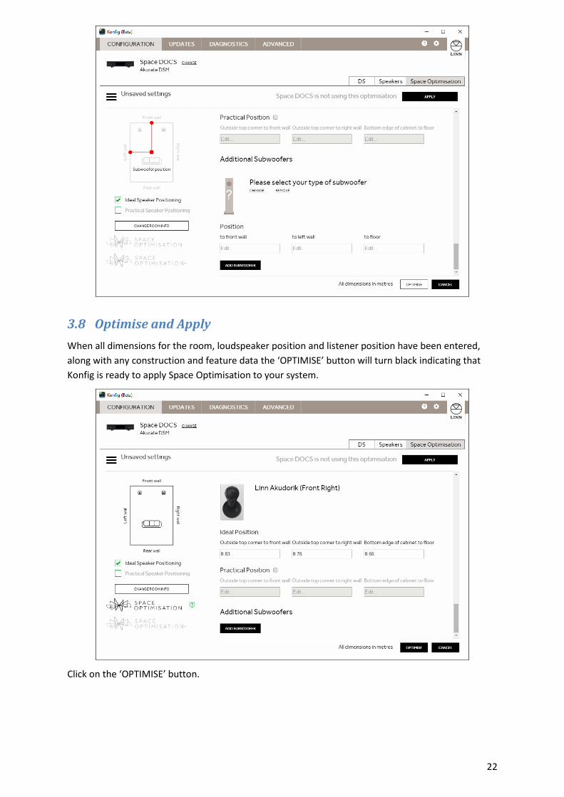
3.8 Optimise and Apply
When all dimensions for the room, loudspeaker position and listener position have been entered,
along with any construction and feature data the ‘OPTIMISE’ button will turn black indicating that
Konfig is ready to apply Space Optimisation to your system.
Click on the ‘OPTIMISE’ button.
Page 23
23
Konfig will now calculate the optimisation filters for room modes and loudspeaker placement (if
practical placement has been entered for the loudspeakers). Once calculated the screen will change
to show the result of the room mode optimisation algorithm.
These settings have NOT been sent to the Exakt system until you press the ‘APPLY’ button.
The ‘APPLY’ button will disappear and a message will be displayed showing that the DS or DSM
system is now using the currently displayed optimisation settings.
For information about further adjustment of the filters produced by Space Optimisation or Space
Optimisation+, including setting bass and treble shelves and custom filters see the advanced set-up
section.
Page 24
24
3.9 Storage of Space Optimisation set-ups
3.9.1 Saving your Space Optimisation
You can save the settings at any time using the button and select ‘SAVE’.
You will be presented with a dialogue box where you can enter a name for the optimisation setup.
This should normally include the room name and any extra detail about the settings you are storing.
Click on the tick symbol to save the setup.
If you make changes to the setup you should use the ‘SAVE AS’ button to avoid overwriting the
existing saved room optimisation.
Page 25
25
3.9.2 Loading Space Optimisation
The settings can be re-loaded at any time by clicking button then ‘OPEN’ button and selecting
the stored file.
Be aware that clicking the cross box on any saved optimisation will permanently delete that
optimisation file.
Page 26
26
3.9.3 Import and Export
It may be desirable to safeguard your finalised optimisation set-up by storing the saved files in a
separate location other than your PC/MAC. Konfig provides the capability to import or export saved
setup files.
Within the load setup page on the Konfig optimisation page there are two buttons; ‘IMPORT’ and
‘EXPORT’, these can be used to back-up any saved optimisation set-up files.
If you only wish to EXPORT some files then type in the filter/search box on the top right text that is
common to the systems you wish to export, such as "John Smith" will only show systems with John
Smith in the ‘ROOM’ or ‘DESCRIPTION’ columns.
Page 27
27
Clicking on ‘IMPORT’ or ‘EXPORT’ will open a standard file load/save dialog.
Page 28
28
4 Setting up Space Optimisation+ for Exakt Surround systems
Exakt surround systems can be configured using either a DSM or an Exakt DSM. A system set-up with
a DSM permits the use of the analogue output channels from the DSM for any pair of channels in the
surround system (e.g. surround left / right).
The basic set-up process for Space Optimisation+ will be familiar to existing users of Space
Optimisation. Those unfamiliar with Space Optimisation should read section 3 before continuing
with this guide.
ENSURE THAT YOU HAVE HDMI: - ENABLED WITH THE KONFIG : DEVICE page
4.1 Assigning speakers within a surround system
Click on the ‘Exakt’ tab near the top of the Konfig screen.
If the system contains integrated Exakt loudspeakers Konfig will populate them automatically into
the list. Any Exaktboxes will need to be configured manually. Once you have selected any speakers
connected to your Exaktbox all speakers require to be assigned by channel in the surround system.
Page 29
29
4.1.1 Full Exakt surround system
When all speakers are assigned to their respective output channels click on the ‘APPLY’ button at the
bottom of the screen.
If you have previously used the analogue outputs from DSM ensure that these are deselected. Scroll
to the bottom of the screen to see the analogue outputs. If these have an assigned speaker click on
‘CLEAR’ for each of the analogue outputs and click on the ‘APPLY’ button.
Page 30
30
4.1.2 Mixed Exakt and Analogue surround system
You can output any two channels in the surround system to the analogue outputs of a DSM.
If you are using a mixed Exakt and analogue system, assign the Exakt speakers and select the
appropriate channels for the analogue output channels. Click on the ‘APPLY’ button.
Page 31
31
4.1.3 Subwoofer assignment
There are two principle ways that subwoofers can be integrated into an Exakt surround system, the
choice will depend on the most common use of the system.
Surround: If the Exakt system is principally used as a home cinema the subwoofers will be defined as
LFE (low frequency effects). The LFE channel of the multi-channel programme material will be sent
to the subwoofer(s) only. The subwoofers will not be included in two channel music playback.
Throughout this document we will refer to this use case as ‘LFE mode’.
Note: The ExaktBox-Sub or the Linn DSM analogue outputs can be configured to output the
LFE channel
Two Channel music: If the system is principally used for two channel music playback and you desire
the subwoofer(s) to contribute to playback in the two channel system the subwoofer(s) will be
defined as MONO, LEFT or RIGHT. In this case the subwoofer(s) will receive the front left, front right,
or mono down-mix of the front left and front right channels.
Note: This will ONLY work with Exakt Front speakers (dedicated or Exaktbox) and ExaktBox-
Sub. Assigning front speakers fed from Linn DS/DSM analogue sockets with Exaktbox-Sub or
Exakt loudspeakers, with Sub fed from Linn DS/DSM analogue sockets will not work.
4.1.3.1 Exaktbox Sub set-up
If your subwoofer(s) are connected to the system using an Exaktbox Sub, select the model of your
subwoofer then select the variant to suit the use-case selection described above.
Assign the channel as appropriate for the chosen use-case.
Page 32
32
Click the ‘APPLY’ button.
4.1.3.2 Analogue Subwoofer set-up
This will ONLY work in Surround mode.
If you choose to employ the analogue output of you DSM to feed your subwoofer(s), select the
manufacturer and model of your subwoofer by clicking on ‘SELECT SPEAKER’ on the chosen analogue
output. In the channel list-box select the channel based on the use-cases detailed above.
Page 33
33
4.2 Set-up Space Optimisation+
Once all speakers are assigned to their respective output channels, click on the ‘SPACE
OPTMISATION+’ tab.
Follow the set-up and room configuration instructions detailed in sections 3.3 to 3.6.
When all room details, including dimensions, construction and features are entered, along with the
listening position and locations of all speakers in the multi-channel set-up, click the ‘OPTIMISE’
button. After a moment you will see the Space Optimisation+ screen. Click ‘APPLY’ to apply the
optimisation.
Page 34
34
4.3 Further tuning of the Space Optimisation+ surround set-up
Ideally the location of the speakers in a home theatre application will follow the recommendations of
Dolby. These may not represent the ideal location of the speakers according to Tune-dem. Careful
use of the features offered by Space Optimisation+ can bring significant improvements to surround
sound quality.
Linn have always recommended the use of Tune-dem to establish the ideal location for loudspeakers
and subsequently top get the best possible sound employing the capabilities of Space Optimisation.
This has traditionally been applied to stereo loudspeaker systems and is not easily transferable to
multi-channel programme material. To facilitate the use of Tune-dem to improve your Exakt
surround set-up we have added two additional features not present on the standard two-channel
Space Optimisation screen; the ‘Filters for’ drop down list, and the ‘Listen to only these speakers’
check box.
Changing the selection in the ‘Filters for’ drop down list switches between common channels within
the surround system. When a channel is selected the graph and associated controls will change to
reflect the optimisation applied to the displayed channels.
If your subwoofers are used in LFM mode they will be integrated into the front left and front right
loudspeakers optimisation. If the subwoofers are used in LFE mode, they will be independently
selectable via the ‘Filters for’ drop down list.
The selectable speaker groups are:
FRONT LEFT & RIGHT or FRONT LEFT & RIGHT & SUBS
CENTRE
SUBS (depending on use case)
SURROUND LEFT & RIGHT
REAR LEFT & RIGHT
Page 36
36
4.3.1 Manual adjustment of the calculated room mode filters
With a channel group selected advanced manual adjustments can be made to the optimisation
settings. Checking the ‘Listen to only these speakers’ checkbox will reconfigure the system such that
stereo music can be played through the selected channel group. All other channels will be muted.
Front Left and Right
Select FRONT LEFT & RIGHT from the ‘Filters for’ drop down list and check the ‘Listen to only these
speakers’ checkbox to play stereo music through the front left and front right channels. If you have
configured your subwoofer(s) for LFM mode they will be included in any adjustments to the room
mode filters for Front left and front right.
Using the process detailed in section 5.2 adjust the room mode gains frequencies and bandwidths
using Tune-dem to evaluate any changes.
Other channels
To make further adjustments to the room mode filters for other channels in the surround system,
select the appropriate channel group and check the ‘Listen to only these speakers’ checkbox.
Page 37
37
Quite often the locations of the remaining channels in a surround system are dictated by furnishings
or construction of the room. In such cases use of the ‘Virtual Tune-dem‘ approach to improve the
tonal balance of centre, surround and rear channels. Details of this approach are presented in
section 3.6.3.
To set the ‘Practical Position’ of the speakers and subsequently adjust the ‘Ideal Position’, click on the
‘CHANGE ROOM INFO’ button and scroll down to find the loudspeaker you wish to adjust using the
‘Virtual Tune-dem’ method.
Following an adjustment click on the ‘OPTIMISE’ button, then click the ‘APPLY’ button.
Page 38
38
5 Advanced set-up for Space Optimisation and Space
Optimisation+
Space Optimisation and Space Optimisation+ will produce very accurate models of the low frequency
interaction between the loudspeakers, room and listening position in a regular rectangular shaped
room. There are often cases, however, where some adjustment of the predicted room mode
solution is required. For example, if the room does not closely conform to a rectangular floorplan
the mode estimates are likely to be in error. Also if the method of construction does not closely
match the options provided in Konfig the amount of cut applied for room modes may be in error.
This advanced set-up guide presents further information about the calculation and manipulation of
room mode filters.
The correct methodology for adjusting the room mode optimisation filters is presented in section
5.2.
Guidelines for simplifying non-rectangular room layouts to better fit to the idealised model are
presented in section 5.5.
Additional filters are available in Space Optimisation and Space Optimisation+ which may also prove
useful in some applications. These include bass and treble shelving filters, and user defined custom
filters. Examples are given where these filters could be of benefit in odd shaped rooms
5.1 Room modes
Konfig provides information which will benefit an experienced installer and allow him to more quickly
identify which mode filters will need to be adjusted, and in what way. To make use of this
information it is useful to understand the limitations of the Konfig room mode calculation resulting
from the assumptions made by the algorithms.
Presented in this section are the fundamental assumptions employed by the room mode
optimisation algorithms. Also recommendations for when to adjust the room mode filter centre
frequency and bandwidth are presented.
5.1.1 Basic assumptions used for calculations of room modes
The optimisation algorithm assumes that the room is of essentially rectangular layout. This is often
not the case. For Konfig to provide a meaningful room mode optimisation more complicated room
shapes must be simplified to approximate rectangular dimensions. How the room is simplified will
dictate the adjustment required to the Konfig optimisation.
All reflections at room boundaries are considered to be specular. This implies that the reflective
characteristics are ideal and are the same at all frequencies. Most real surfaces do not provide
specular reflections, instead the magnitude and phase response of any reflected wave is dependent
on the incident angle of the acoustic wave. This has significant implications for any non-axial mode
(a mode which operates between more than two parallel surfaces).
Page 39
39
5.1.2 How room mode filters are displayed and adjusted
Go to the Space Optimisation tab within Konfig. Below the room mode filter graph you will see a
popup list-box showing the room mode optimisation filters. The popup list also allows access to bass
and treble shelves and custom filters.
Selecting an individual optimisation filter allows you to modify its behaviour.
Room modes and their optimisation filters are calculated on a single speaker basis and are listed in
ascending frequency; the lowest frequency room mode will be optimised by ‘ROOM MODE 1’.
Each room mode will be active across one or more dimensions of the room, indicated by the square
bracket notation in the popup list. This information will be of great use to an experienced installer,
further comment is made below.
Some room modes will be unique to a single loudspeaker; some will be common across a pair of
loudspeakers. This is also indicated in the popup list.
Adjustment of room modes in Konfig
When a room mode filter is selected from the drop down list the user is provided with the full
specification of the parametric equalising filter applied to optimise for the room mode.
For mode filters which are unique to one speaker (left or right) a set of three parameters will be
displayed, centre frequency, gain and bandwidth. These parameters fully describe the room mode
optimisation filter being applied and each may be adjusted to better optimise for a given room
mode.
The user is permitted to vary the filter gain by ±100%, the centre frequency by ±2 Hz and the
bandwidth of the filter by ±10%.
Page 40
40
For room mode optimisation filters that are ‘common’ across a pair of loudspeakers the three
parameters will be displayed for both loudspeakers. Any adjustments made to the filter will be
applied to both loudspeakers.
For ‘common’ filters the bandwidth and frequency of the left and right filters will always be identical,
any change to bandwidth or frequency on one speaker will be reflected across the pair.
The gain of ‘common’ filters will often be different. Konfig will attempt to maintain the gain
difference between the left and right room mode optimisation filters for ‘common’ filters. In this
case adjusting one speaker by 1 dB will also change the paired speaker’s filter by 1 dB. Neither of the
optimisation filters can be extended to provide positive gain, when one filter reaches 0 dB Konfig will
no longer maintain the gain difference.
Page 41
41
This is indicated well by examining ‘ROOM MODE 3’ in the example below:
For ‘ROOM MODE 3’ the left and right filters show a gain difference on 14.89 dB. Increasing the gain
of either speaker by 6 dB results in a left filter gain of -15.85 dB and a right filter gain of -0.96 dB. The
14.89 dB difference is maintained.
Adjusting the left speaker by a further 3 dB now gives a left filter gain of -12.85 dB, but a right filter
gain of 0 dB.
Page 42
42
The left filter gain can continue being increased until it also reaches 0 dB with no further effect on
the right filter gain.
With both filter gains set to 0 dB, a decrease of 1 dB to the right filter gain results in the left speaker
gain setting itself to -15.89 dB. Konfig has re-applied the gain difference of 14.89 dB.
Page 43
43
Additional information provided by Konfig
Konfig provides dimensional information about the room modes. The room mode filter titles shown
in the drop down list also include a set of three characters in square brackets. This describes the axis
of the room along which the standing waves of the room mode occur.
Modes active along the length axis of the room are shown as [L--].
Those active across the width or height are shown as [-W-] and [--H] respectively.
The mode descriptor will inform the installer whether a mode is a simple axial mode (operating along
a single room dimension) or if the mode is tangential or oblique (operating between four or six room
surfaces).
This is very useful information for the experienced installer. A length mode will be controlled by the
characteristics of the front and rear walls. Say, for example, the room has a pitched roof; any height
mode will need to be adjusted.
Due to the non-ideal reflective characteristics of real surfaces any non-axial mode is likely to be over-
optimised by Konfig. The installer will know that any mode described by more than one letter (e.g.
[L-H] or [LW-]) is likely to require adjustment, typically an increase in filter gain (less cut).
Page 44
44
5.2 Improving the estimated room mode optimisation using Tune-dem
Due to assumptions made in the room mode algorithms there will be scope for further optimisation
of the filters applied by Space Optimisation. The process that should be adopted is detailed below.
5.2.1 Room mode filter validity
As a first step it is recommended that the installer check the validity of each room mode filter. Filter
redundancy may occur if a room surface is particularly irregular, for example a pitched roof. In this
instance no strong standing waves will occur between the floor and ceiling and unnecessary
optimisation filters may be produced.
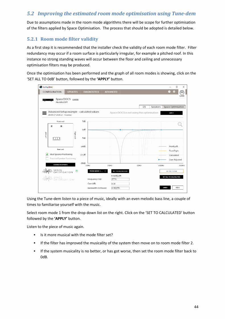
Once the optimisation has been performed and the graph of all room modes is showing, click on the
‘SET ALL TO 0dB’ button, followed by the ‘APPLY’ button.
Using the Tune-dem listen to a piece of music, ideally with an even melodic bass line, a couple of
times to familiarise yourself with the music.
Select room mode 1 from the drop down list on the right. Click on the ‘SET TO CALCULATED’ button
followed by the ‘APPLY’ button.
Listen to the piece of music again.
Is it more musical with the mode filter set?
If the filter has improved the musicality of the system then move on to room mode filter 2.
If the system musicality is no better, or has got worse, then set the room mode filter back to
0dB.
Page 45
45
Using the Tune-dem re-instate each filter in turn, always starting with the lowest frequency, and
ensure that each optimisation filter improves the musicality of the system. If re-instating a filter has
no audible effect then return the filter’s gain to zero and move to the next filter
5.2.2 Adjusting room mode filters for best sonic performance
Once all required room mode optimisation filters have been established some further optimisation
may be achieved by altering the gain of the room mode filters (examples of when to adjust frequency
and bandwidth are covered in next section).
Use a piece of music with an even, melodic bass line.
Starting with the lowest frequency room mode filter, increase the gain by 6dB (towards 0 dB)
and listen again.
Using Tune-dem decide if the result is an improvement.
If the bass line sounds more even, try increasing the gain again.
If the bass line sounds less even, then reduce the gain.
Increase and decrease the gain in progressively smaller steps until the best result is achieved.
Move on to the next valid room mode and repeat.
Always start with the lowest frequency room mode filter. Low frequencies mask higher frequencies
so it will be easier to judge the accuracy of the higher frequency mode filters if the lower frequency
filters are correct.
Page 46
46
5.3 Additional filtering capability
In addition to the automatically calculated room modes filters and Practical Position filters users of
Space Optimisation and Space Optimisation+ can add further manual filters.
5.3.1 Bass and Treble shelves
An additional pair of filters is available in Space Optimisation and Space Optimisation+, namely the
bass and treble shelves. These may be considered as a highly flexible and customisable equivalent to
a classic tone control.
The treble shelf can be varied between + 2dB and -2dB with a corner frequency between 8 kHz and
12 kHz. For rooms with a large amount of soft furnishings, or for installations where the listening
position is further from the loudspeakers than is typical the high frequency shelf can be employed to
add lift to the treble. Conversely if the room contains mainly hard reflective surfaces some cut may
be required to calm to top end of the music spectrum. When applying a treble shelf ensure you click
on the magnifying glass symbol on the plot area to ensure you get a visual representation of the filter
being applied.
The low frequency shelf can apply cut or boost to low frequencies with a corner between 20Hz and
200Hz. The limits of cut and boost are specific to each model of speaker but typically cover the range
-6dB to + 3dB. It is generally advisable when applying boost to set the corner frequency at 65Hz or
lower to avoid disrupting the vocal presentation of the system.
Both treble and bass shelves are user configurable and the Tune-dem should be utilised when making
adjustments.
Page 47
47
5.3.2 Custom filters
Users may add up to four custom filters. These may be specified by selecting one of the custom
filters from the drop down list and entering the three parameters (Frequency, Gain and Bandwidth).
Custom filters apply globally across the currently selected loudspeakers (left and right for a stereo
system, across channel groups in a surround system).
The parameters applied to define a custom filters may be derived by trial and error and Tune-dem or
by information captured by a third party measurement system. As with the bass and treble shelf
filters positive gain can be applied when using a custom filter. This is limited to 2 dB to avoid risk of
damage to the attached loudspeakers.
Page 48
48
5.4 Simplifying room dimensions
The room optimisation algorithm in Space Optimisation is based on the assumption of a largely
rectangular room. If the room is slightly non-rectangular (e.g. it has a chimney breast or a bay
window) you must decide upon the pertinent dimensions. In general the room dimension should be
taken as the distance corresponding to the largest surface area on any given wall. Taking the
examples cited above; in the case of the bay window, if the window covers more than half of the wall
then measure into the bay window. For the case of the chimney breast, if the chimney covers less
than half of the wall surface then measure to the wall either side of the chimney.
If a room is rectangular but has one corner taken up by a partitioned corridor or small anteroom then
the larger dimensions should be used.
5.4.1 Simplifying a room to rectangular dimensions
Presented below are some examples of non-ideal rooms and how they should be simplified to fit the
rectangular model employed by Konfig. In addition some recommendations are given for each room
likely to improve the optimisation produced by the simplified rectangular model.
Example room 1, chimney breast and bay window.
In general when measuring a room the dimension should be taken which corresponds to the largest
parallel surface area of opposite walls. In the example above, the inset door and chimney breast
(fireplace) account for less than 50% of the side walls so they are ignored and the measurement
taken is to the most distant surfaces (4.3m). The bay window covers more than 50% of the end wall
so the length of the room is measured into the window (6.15m).
As the bay window along with the remainder of the front wall forms a staggered surface some
smearing of room modes relating to the length of the room may occur. This can be countered by
slightly increasing the bandwidth of any length modes.
Page 49
49
Example room 2, room with one angled wall
Where walls are angled it is recommended to take an average measurement. For the room below
the length remains at 6.15, measured into the bay window. The width would be taken as 4.1m, the
average width.
Modes relating to the width of the room will need further attention. It is likely that the optimisation
filter gain for width modes will need to be reduced as non-parallel walls will reduce the strength of
any modal behaviour. It may also be beneficial to increase the bandwidth of any width modes to
capture the spread of modal frequencies resulting from the non-parallel surfaces.
Page 50
50
Example room 3, room with pitched roof
For a room with a pitched roof careful attention to any room modes operating in the vertical axis is
required. The most reliable approach for optimising room modes where a pitched roof is present is
to take the height measurement to approximately one third of the way up the pitched roof. Run
through the modal validity checks (detailed in section 3.2.1) to ensure that any calculated height
modes are providing benefit. If benefit is found the calculated mode filter may be improved by
increasing the bandwidth (5% to 10%) and gain (less cut).
For the example room below this corresponds to a height of 2.7m, an increase in bandwidth of any
height modes of between 5% and 10%.
As the floor plan of the room is a pure rectangle the width and length of the room are as given (4.3m
and 6.15m).
5.5 Approach for rooms which may not be simplified
In many cases the floorplan of a room may be too complicated to reduce to a simplified rectangular
shape. Often, if the room is highly irregular, this may not be too much of a problem as there will be
few parallel surfaces between which strong room modes will occur. In other cases where parallel
surfaces are evident but the room is impractical to simplify the use of custom filters may prove
useful.
This section introduces several such spaces and provides guidance on how to tackle the room mode
solution through both the room mode optimisation algorithm as well as the application of custom
filters.
Page 51
51
5.5.1 Example room 4, L-shaped
A more challenging room shape to configure for room mode optimisation is an L-shaped room. The
approach adopted will often depend on the location of the loudspeakers and listening position within
the room.
The layout presented below presents quite a dilemma with regard to simplifying the room to a
rectangular form. In this case the L-shape splits the room in half along the longest dimension. This
makes it impossible to apply the approach where a dimension is dictated by the largest parallel
surface of opposite walls (remember the bay window example). If the L-shape had split the room
off-centre the choice of room dimensions would be simplified.
Taking the layout presented below, depending on the location of the loudspeakers and listening
position there exist three sets of dimensions which could be appropriate for specifying the room in
Konfig, namely; 6.3m by 5.9m, 3.9m by 6.3m, or 3.15m by 5.9m.
It may be that the best solution to the problem would be a combination of the mode solutions from
two of these possible sets of dimensions. This was a principle reason for the addition of custom
filters in Space Optimisation.
For this example, the loudspeakers are placed on the right side across the 3.9m width firing along the
6.3m length of the room. The initial rectangular layout would have a length of 6.3m and a width of
3.9m.
Let us set the listening position at 4.3m from the front wall, central with regard to the loudspeakers.
The loudspeakers, a pair of Akubariks, are placed 1m from the front wall and 0.75m from the side
walls.
Page 52
52
The first model room mode algorithm predicts the following four modes:
Calculated Mode Channel Frequency (Hz) Gain (dB) L/R Bandwidth (Octaves)
ROOM MODE 1 [L--] L/R 27.30 -27.59/-27.59 0.196209
ROOM MODE 2 [L--] L/R 54.60 -16.50/-16.50 0.098161
ROOM MODE 3 [--H] L/R 68.80 -12.31/-12.31 0.077911
ROOM MODE 4 [L-H] L/R 74.02 -13.11/-13.11 0.072419
All four modes are common to both speakers, a result which is unsurprising due to the symmetry of
the set-up within the model. Following the Tune-dem process outlined in section 3.2, all modes are
found to be valid but the room still sounds modal.
A second model is then produced extending the left wall to the full extent of the L-shaped room. The
rectangular layout now has a length of 6.3m and a width of 5.9m. The listening position and left
hand speaker move 2m further from the left wall.
Page 53
53
The room mode algorithm predicts 9 room modes:
Calculated Mode Channel Frequency (Hz) Gain (dB) L/R Bandwidth (Octaves)
ROOM MODE 1 [L--] L/R 27.30 -24.91/-23.06 0.173860
ROOM MODE 2 [LW-] R 39.94 0.0/-19.91 0.118881
ROOM MODE 3 [L--] L/R 54.60 -13.22/-14.87 0.086969
ROOM MODE 4 [-W-] L/R 58.31 -16.86/-15.31 0.081449
ROOM MODE 5 [LW-] R 61.90 0.0/-13.91 0.076722
ROOM MODE 6 [LW-] L 64.38 -15.97/0.0 0.073765
ROOM MODE 7 [--H] L/R 68.80 -7.71/-9.61 0.069027
ROOM MODE 8 [L-H] L 74.02 -11.38/0.0 0.064161
ROOM MODE 9 [LW-] L 79.88 -10.27/0.0 0.059453
The large number of modes is principally due to the off-centre set-up within the room, a situation
which is characterised by the prevalence of single speaker modes.
Using the room mode validation process detailed in section 3.2 modes 2, 6 and 9 are found to offer
no improvement so can be set to zero.
All four room modes identified in the first model are present in the second, confirming the result of
the Tune-dem evaluation already conducted, though the second model omits the right hand speaker
from the mode optimisation at 74.02 Hz.
It should also be noted that all four room mode filters common to both models show reduced gain in
the second model. This is due to the increase in absorptive surface area and increased room volume
Page 54
54
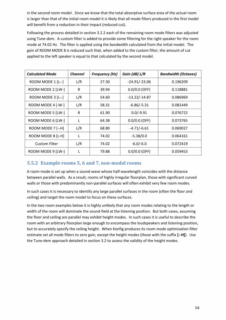
in the second room model. Since we know that the total absorptive surface area of the actual room
is larger than that of the initial room model it is likely that all mode filters produced in the first model
will benefit from a reduction in their impact (reduced cut).
Following the process detailed in section 3.2.2 each of the remaining room mode filters was adjusted
using Tune-dem. A custom filter is added to provide some filtering for the right speaker for the room
mode at 74.02 Hz. The filter is applied using the bandwidth calculated from the initial model. The
gain of ROOM MODE 8 is reduced such that, when added to the custom filter, the amount of cut
applied to the left speaker is equal to that calculated by the second model.
Calculated Mode Channel Frequency (Hz) Gain (dB) L/R Bandwidth (Octaves)
ROOM MODE 1 [L--] L/R 27.30 -24.91/-23.06 0.196209
ROOM MODE 2 [LW-] R 39.94 0.0/0.0 (OFF) 0.118881
ROOM MODE 3 [L--] L/R 54.60 -13.22/-14.87 0.086969
ROOM MODE 4 [-W-] L/R 58.31 -6.86/-5.31 0.081449
ROOM MODE 5 [LW-] R 61.90 0.0/-9.91 0.076722
ROOM MODE 6 [LW-] L 64.38 0.0/0.0 (OFF) 0.073765
ROOM MODE 7 [--H] L/R 68.80 -4.71/-6.61 0.069027
ROOM MODE 8 [L-H] L 74.02 -5.38/0.0 0.064161
Custom Filter L/R 74.02 -6.0/-6.0 0.072419
ROOM MODE 9 [LW-] L 79.88 0.0/0.0 (OFF) 0.059453
5.5.2 Example rooms 5, 6 and 7, non-modal rooms
A room mode is set up when a sound-wave whose half-wavelength coincides with the distance
between parallel walls. As a result, rooms of highly irregular floorplan, those with significant curved
walls or those with predominantly non-parallel surfaces will often exhibit very few room modes.
In such cases it is necessary to identify any large parallel surfaces in the room (often the floor and
ceiling) and target the room model to focus on these surfaces.
In the two room examples below it is highly unlikely that any room modes relating to the length or
width of the room will dominate the sound-field at the listening position. But both cases, assuming
the floor and ceiling are parallel may exhibit height modes. In such cases it is useful to describe the
room with an arbitrary floorplan large enough to encompass the loudspeakers and listening position,
but to accurately specify the ceiling height. When Konfig produces its room mode optimisation filter
estimate set all mode filters to zero gain, except the height modes (those with the suffix [--H]). Use
the Tune-dem approach detailed in section 3.2 to assess the validity of the height modes.
Page 55
55
Example room 5: Curved walls
Example room 6: Irregular floorplan
5.5.2.1 Example room 7: Non-parallel walls
The final example room (example 7), one with essentially non-parallel walls should be treated in the
same way as the curved wall and irregular floorplan rooms. Two additional features of this example
installation may benefit from the application of custom filters.
Page 56
56
The first likely issue is the anteroom adjoining the listening space with an open doorway. This may
exhibit a resonance separate from the principle listening space. Little can be done to model this
room and its impact on the room mode solution, but a custom filter may be applied to reduce its
impact on the performance of the system. Setting the custom filter could be done by analysing the
anteroom issue with a third party acoustic measurement acoustic system, though it is likely that a
good result could be found tuning the filter by ear. Set the custom filter a reasonably wide
bandwidth and a gain of -10 dB, adjust the frequency until the impact of the anteroom resonance on
the music is reduced. Now the filter is roughly centred apply the Tune-dem to gradually fine tune the
bandwidth, gain and frequency.
A second likely problem with the installation is the close proximity of the speakers to the sidewalls.
This may well result in excess boundary support in the upper bass and lower midrange. Placement
optimisation is designed to function when the loudspeaker is bounded by two perpendicular planes,
in other words the speaker should be located near the corner of a room. In the example above
neither speaker is located in a true corner so placement optimisation will be unable to accurately
resolve the tonal issues due to this loudspeaker placement. A custom filter should be applied. Set
the frequency to lie in the problem range, around 140 Hz. Give the filter a wide bandwidth, ~ 3
octaves and a gentle cut of about 2dB. Use the Tune-dem to adjust the filter.