SSP 30219 Space Agency National Aeronautics and Space Administration International Space Station Program Johnson Space Center Houston, Texas International Space Station Program Revision F Space Station Reference Coordinate Systems National Space Development Agency of Japan esa european space agency Russian 26 October 2001
Transcript
SSP 30219
SpaceAgency
National Aeronautics and Space AdministrationInternational Space Station ProgramJohnson Space CenterHouston, Texas
A REVISION A IS IDENTICAL IN CONTENT TO THE BASELINE ISSUE. IT HAS BEEN REFORMATTED TO AGREE WITH THE DOCUMENTATIONFORMAT REQUIREMENTS DESCRIBED IN JSC 30200, THIRD DRAFT.FEBRUARY 15, 1987 06–15–87
B REVISION B (REFERENCE THE ELECTRONIC BASELINEREFORMATTED VERSION) 10–15–88
C REVISION C (REFERENCE SSCBD BB003460 EFF. 3–8–93) 3–93
D REVISION D (Reference SSCBD 00002, Eff. 2–1–94) 05–13–94CN001 Incorporated TDC–431 (SSCBD 000008R1,
E REVISION E (Reference SSCD 000580, Eff. 9–4–98) 11–19–98(FOR NASA AND NASA CONTRACTOR USE ONLY)
CN002 INCORPORATES SSCD 000580, Eff. 9–4–88 11–19–98(PREIMPLEMENT FOR NASA AND CONTRACTOR USE – SSCN 001334)
F Revision FIncorporates SSCN 003299.
The following DCN has been cancelled. The content of the SSCNs authorizing release of the DCN has been incorporated into Revision F.DCN 003 (SSCN 000256) (Administrative Cancel)
SSP 30219 Revision F 26 October 2001
i
PREFACE
The purpose of this document is to establish a set of coordinate systems to be used whenreporting data between the Space Station Program Participants (SSPP).
This document contains figures defining configuration dependent, configuration independent,articulating, viewing, unpressurized, translating, pressurized, and transverse boom framereferences frames. In addition, appendixes are included with abbreviations and acronyms, aglossary, subscript designations, and reference documents.
The contents of this document are intended to be consistent with the tasks and products to beprepared by Space Station Program (SSP) participants as defined in SSP 41000, SystemSpecification for Space Station. The Space Station Reference Coordinate Systems shall beimplemented on all new SSP contractual and internal activities and shall be included in anyexisting contracts through contract changes. This document is under the control of the SpaceStation Control Board, and any changes or revisions will be approved by the Program Manager.
SSP 30219 Revision F 26 October 2001
ii
INTERNATIONAL SPACE STATION PROGRAM
SPACE STATION REFERENCE COORDINATE SYSTEMS
26 OCTOBER 2001
CONCURRENCE
PREPARED BY:
CHECKED BY:
SIGNATURE
SUPERVISED BY
PRINT NAME ORGN
DATE
SIGNATURE
PRINT NAME ORGN
DATE
SUPERVISED BY
SIGNATURE
PRINT NAME ORGN
DATE
SIGNATURE
PRINT NAME ORGN
DATE
DQA:
SIGNATURE
PRINT NAME ORGN
DATE
(BOEING):
(NASA):
Felipe Sauceda
Gregory B. Ray
Bob Korin
Nancy Wilks
2–6610
OM
Lucie Delheimer
5–5332
5–5332
5–5310
SSP 30219 Revision F 26 October 2001
iii
NASA/ASI
INTERNATIONAL SPACE STATION ALPHA PROGRAM
SPACE STATION REFERENCE COORDINATE SYSTEMS
26 OCTOBER 2001
DATEFor NASA
3/11/94/s/ Dale Thomas
For ASI DATE
/s/ Andrea Lorenzoni 3/16/94
SSP 30219 Revision F 26 October 2001
iv
NASA/CSA
INTERNATIONAL SPACE STATION ALPHA PROGRAM
SPACE STATION REFERENCE COORDINATE SYSTEMS
26 OCTOBER 2001
DATEFor NASA
/s/ Dale Thomas 3/14/94
For CSA DATE
Agreed to in principal subject to completion of detailed review by CSA and itscontractor.
/s/ R. Bryan Erb 3/14/94
SSP 30219 Revision F 26 October 2001
v
NASA/ESA
INTERNATIONAL SPACE STATION ALPHA PROGRAM
SPACE STATION REFERENCE COORDINATE SYSTEMS
26 OCTOBER 2001
DATEFor NASA
/s/ Dale Thomas 3/11/94
For ESA DATE
/s/ Helmut Heusmann 3/23/94
Pending definition of AR5XATV launched APM coordinate system origin, ref. ESALetter MES/007/94/HH/em, dated 23 Feb, 1994.Note: Document not called up as applicable to ESA.
SSP 30219 Revision F 26 October 2001
vi
NASA/NASDA
INTERNATIONAL SPACE STATION ALPHA PROGRAM
SPACE STATION REFERENCE COORDINATE SYSTEMS
26 OCTOBER 2001
DATEFor NASA
Dale Thomas 3/11/94
DATE
Kuniaki Shiraki 3/17/94
Agreed to in principal subject to completion of detailed review byNASDA.
For NASDA
SSP 30219 Revision F 26 October 2001
vii
NASA/RSA
INTERNATIONAL SPACE STATION ALPHA PROGRAM
SPACE STATION REFERENCE COORDINATE SYSTEMS
26 OCTOBER 2001
DATEFor NASA
/s/ Dale Thomas 3/11/94
For RSA DATE
SSP 30219 Revision F 26 October 2001
viii
SPACE STATION PROGRAM OFFICE
SPACE STATION REFERENCE COORDINATE SYSTEMS
LIST OF CHANGES
26 OCTOBER 2001
All changes to paragraphs, tables, and figures in this document are shown below:
SSCBD ENTRY DATE CHANGE PARAGRAPH
3299 10/26/01 1.3 PRECEDENCE
5.0 ARTICULATING AND TRANSVERSEBOOM REFERENCE FRAMES
8.0 TRANSLATING REFERENCE FRAMES
9.0 PRESSURIZED MODULE REFERENCEFRAMES
TABLE(S)
10/26/01 NONE.
FIGURE(S)
3299 10/26/01 ALL FIGURES WERE CHANGED FORUPDATE TO CORRECT FORMAT.ADDITIONAL CHANGES WERE MADETO THE FOLLOWING:
3.0–15 RUSSIA ORBITAL COORDINATESSYSTEM
3.0–16 RSO: RUSSIAN SUN EQUILIBRIUMATTITUDE COORDINATES SYSTEM
4.0–2 SPACE STATION REFERENCECOORDINATE SYSTEM
4.0–4 RSA ANALYSIS COORDINATE SYSTEM
4.0–9 SOYUZ TM TRANSPORT MANNEDVEHICLE COORDINATE SYSTEM
4.0–10 PROGRESS–M TRANSPORT CARGOVEHICLE COORDINATE SYSTEM
4.0–12 AUTOMATED TRANSFER VEHICLECOORDINATE SYSTEM
4.0–13 H–II TRANSFER VEHICLECOORDINATE SYSTEM, MECHANICALDESIGN REFERENCE
SSP 30219 Revision F 26 October 2001
ix
LIST OF CHANGES – Continued
3299 – contd. 10/26/01 4.0–14 H–II TRANSFER VEHICLECOORDINATE SYSTEM, ATTITUDEREFERENCE
5.0–1 STARBOARD SOLAR POWER MODULECOORDINATE SYSTEM
5.0–2 INTEGRATED TRUSS SEGMENT S4COORDINATE SYSTEM
5.0–3 INTEGRATED TRUSS SEGMENT S5COORDINATE SYSTEM
5.0–4 INTEGRATED TRUSS SEGMENT S6COORDINATE SYSTEM
5.0–5 PORT SOLAR POWER MODULECOORDINATE SYSTEM
5.0–6 INTEGRATED TRUSS SEGMENT P4COORDINATE SYSTEM
5.0–7 INTEGRATED TRUSS SEGMENT P5COORDINATE SYSTEM
5.0–8 INTEGRATED TRUSS SEGMENT P6COORDINATE SYSTEM
5.0–9 SOLAR ARRAY WING COORDINATESYSTEM
5.0–10 THERMAL CONTROL SYSTEMRADIATOR COORDINATE SYSTEM
5.0–11 INTEGRATED TRUSS SEGMENT Z1COORDINATE SYSTEM
5.0–12 INTEGRATED TRUSS SEGMENT S0COORDINATE SYSTEM
5.0–13 INTEGRATED TRUSS SEGMENT S1COORDINATE SYSTEM
5.0–14 INTEGRATED TRUSS SEGMENT S3COORDINATE SYSTEM
5.0–15 INTEGRATED TRUSS SEGMENT P1COORDINATE SYSTEM
5.0–16 INTEGRATED TRUSS SEGMENT P3COORDINATE SYSTEM
5.0–17 FGB ARRAYS COORDINATE SYSTEM
SSP 30219 Revision F 26 October 2001
x
LIST OF CHANGES – Continued
3299 – contd. 10/26/01 5.0–18 SERVICE MODULE ARRAYSCOORDINATE SYSTEM
5.0–19 SCIENCE POWER PLATFORMCOORDINATE SYSTEM
5.0–20 SCIENCE POWER PLATFORMRADIATOR COORDINATE SYSTEM
5.0–21 SCIENCE POWER PLATFORM ARRAYSCOORDINATE SYSTEM
6.0–1 TRACKING AND DATA RELAYSATELLITE SYSTEM (KU–BAND)COORDINATE SYSTEM
6.0–6 EARLY AMMONIA SERVICERCOORDINATE STSTEM
6.0–7 RACK COORDINATE SYSTEM
6.0–8 O2/N2 HIGH PRESSURE GAS TANKCOORDINATE SYSTEM
6.0–9 SOLAR ARAY ORU COORDINATESYSTEM
6.0–10 PUMP MODULE ASSEMBLY ORUCOORDINATE SYSTEM
6.0–11 S1 GRAPPLE BAR ORU COORDINATESYSTEM
6.0–12 RADIATOR ORU COORDINATESYSTEM
6.0–13 THERMAL RADIATOR ROTARY JOINTORU COORDINATE SYSTEM
6.0–14 MAST CANISTER ORU COORDINATESYSTEM
7.0–1 SPACELAB PALLET COORDINATESYSTEM
7.0–3 EXTERNAL STOWAGE PLATFORM – 2
8.0–1 CREW AND EQUIPMENTTRANSLATIONAL AID COORDINATESYSTEM
8.0–3 MOBILE TRANSPORTER COORDINATESYSTEM
SSP 30219 Revision F 26 October 2001
xi
LIST OF CHANGES – Continued3299 – contd. 10/26/01 8.0–4 MOBILE SERVICING CENTRE BASE
SYSTEM COORDINATE SYSTEM
8.0–6 DELETED
8.0–8 JEM – REMOTE MANIPULATORSYSTEM COORDINATE SYSTEM
9.0–1 UNITED STATES LABORATORYMODULE COORDINATE SYSTEM
9.0–2 UNITED STATES HABITATIONMODULE COORDINATE SYSTEM
9.0–3 MINI PRESSURIZED LOGISTICSMODULE COORDINATE SYSTEM
9.0–4 JOINT AIRLOCK COORDINATESYSTEM
9.0–5 CUPOLA COORDINATE SYSTEM
9.0–6 RESOURCE NODE 1 COORDINATESYSTEM
9.0–7 RESOURCE NODE 2 COORDINATESYSTEM
9.0–8 RESOURCE NODE 3 COORDINATESYSTEM
9.0–9 CENTRIFUGE ACCOMMODATIONMODULE COORDINATE SYSTEM
9.0–10 JAPANESE EXPERIMENT MODULE(JEM) — PRESSURIZED MODULE (PM)COORDINATE SYSTEM
9.0–11 JAPANESE EXPERIMENT MODULEEXPERIMENTAL LOGISTICS MODULEPRESSURIZED SECTION COORDINATESYSTEM
9.0–12 JAPANESE EXPERIMENT MODULE —EXPERIMENTAL LOGISTICS MODULEEXPOSED SECTION COORDINATESYSTEM
9.0–13 JAPANESE EXPERIMENT MODULEEXPOSED FACILITY COORDINATESYSTEM
9.0–15 PRESSURIZED MATING ADAPTER–1COORDINATE SYSTEM
SSP 30219 Revision F 26 October 2001
xii
LIST OF CHANGES – Continued
3299 – contd. 10/26/01 9.0–16 PRESSURIZED MATING ADAPTER–2COORDINATE SYSTEM
9.0–17 PRESSURIZED MATING ADAPTER–3COORDINATE SYSTEM
9.0–27 RESEARCH MODULE –1 COORDINATE SYSTEM 9 – 28. . . . . . . . . . . .
9.0–28 RESEARCH MODULE –2 COORDINATE SYSTEM 9 – 29. . . . . . . . . . . .
SSP 30219 Revision F 26 October 2001
1 – 1
1.0 INTRODUCTION
This document contains the definitions of the various coordinate systems used throughout theSpace Station Program.
1.1 PURPOSE
The purpose of this document is to establish a set of coordinate systems to be used whenreporting data between the Space Station Program Participants (SSPP).
1.2 SCOPE
The scope of this document does not extend beyond the realm of communication of data betweenthe SSPPs. Analyses software, preferred conventions, on–orbit operations, on–orbit locationcoding and internal reports can contain data in whatever coordinate system deemed appropriate.
1.3 PRECEDENCE
In the event of a conflict between this document and any previous versions of SSP 30219, SpaceStation Reference Coordinate Systems, this document takes precedence. In the case of a conflictbetween this document and SSP 41000, System Specification for the Space Station; SSP 41000takes precedence. In the event of a conflict between this document and any released SpaceStation engineering drawing or ICD, the released engineering drawing or ICD takes precedence.
1.4 DELEGATION OF AUTHORITY
The responsibility of assuring the definition, control, and implementation of the coordinatesystems defined in this document is vested with the NASA Space Station Program Office, ASI,CSA, ESA, NASDA, and RSA.
SSP 30219 Revision F 26 October 2001
2 – 1
2.0 APPLICABLE DOCUMENTS
The following documents of the date and issue shown are applicable to the extent specifiedherein. Inclusion of applicable documents herein does not in any way supersede the order ofprecedence specified in paragraph 1.3. The references show where each applicable document iscited in this document.
DOCUMENT NO. TITLE
None
SSP 30219 Revision F 26 October 2001
3 – 1
3.0 CONFIGURATION INDEPENDENT REFERENCE FRAMES
The coordinate systems outlined in this chapter are independent of the Space Stationconfiguration. These coordinates systems are mostly global (with the origin at the center of theearth) in nature and can be used for any spacecraft orbiting the earth.
SSP 30219 Revision F 26 October 2001
3 – 2
FIGURE 3.0–1 J200, MEAN OF 2000, CARTESIAN
NAME: J2000, Mean of 2000, Cartesian Coordinate System*
ORIGIN: The center of the Earth.
ORIENTATION: The epoch is 2000 January 1, noon or Julian ephemeris date 2451545.0.
The XJ2000 – YJ2000 plane is the mean Earth’s equator of epoch.
The XJ2000 axis is directed toward the mean vernal equinox of epoch.
The ZJ2000 axis is directed along the Earth’s mean rotational axis of epochand is positive north.
*A source document which discusses the expression of vectors in mean of 2000, rather than mean of1950, coordinates is U.S. Naval Observatory Circular No. 163, “The International Astronomical UnionResolutions on Astronomical Constants, Time Scales, and the Fundamental Reference Frame,” Wash-ington, D.C. 20390, December 10, 1981.
CENTER OF EARTH
MEAN EQUATOROF EPOCH
MEAN VERNALEQUINOX OF EPOCH
EARTH’S MEAN ROTATIONAL AXISOF EPOCH
ZJ2000
XJ2000
YJ2000
SSP 30219 Revision F 26 October 2001
3 – 3
FIGURE 3.0–2 MEAN OF 2000, POLAR
NAME: Mean of 2000, Polar Coordinate System
ORIGIN: For position – the center of the Earth.
For velocity – the point of interest, P (XJ2000, YJ2000, ZJ2000).
ORIENTATION AND DEFINITIONS:
For position – same as in J2000 mean of 2000, Cartesian.
For velocity –
Reference plane is perpendicular to radius vector RJ2000 from center ofEarth to point P of interest
Reference direction is northerly along the meridian containing P
Polar position coordinates of P are:
αJ2000, right ascension, is the angle between projection of radius vectorin the equatorial plane and the vernal equinox of epoch, positive towardeast
δJ2000, declination, is the angle between the radius vector and themean Earth’s equator of epoch, positive toward north
RJ2000, magnitude of RM2000.
Polar velocity coordinates of P are:
Let U, E, N denote up, east, and north directions; then:
ψJ2000, azimuth, is the angle from north to the projection of the inertialvelocity, V2000, on the reference plane, positive toward east
γJ2000, flightpath angle, is the angle between the reference plane andVM2000, positive sense toward U
VJ2000, magnitude of VJ2000
CHARACTERISTICS: Inertial.
RJ2000
ψJ2000
Plane Perpendicular to RJ2000
PositionVelocityZJ2000
XJ2000
YJ2000
RJ2000
J2000
J2000
P
P
UE
VJ2000
Nγ
J2000
SSP 30219 Revision F 26 October 2001
3 – 4
FIGURE 3.0–3 MEAN OF 1950, CARTESIAN
NAME: Mean of 1950, Cartesian Coordinate System
ORIGIN: The center of the Earth.
ORIENTATION: The epoch is the beginning of Besselian year 1950 or Julian ephemeris date2433282.423357.
The XM1950 – YM1950 plane is the mean Earth’s equator of epoch.
The XM1950 axis is directed toward the mean vernal equinox of epoch.
The ZM1950 axis is directed along the Earth’s mean rotational axis of epochand is positive north.
NOTES: This coordinate system is provided to support existing analyses framework.Any new analyses tasks should utilize the J2000, Cartesian CoordinateSystem depicted in Figure 3.0–1.This coordinate system is also referred to as B1950.
CENTER OF EARTH
MEAN EQUATOROF EPOCH
MEAN VERNALEQUINOX OF EPOCH
EARTH’S MEAN ROTATIONAL AXISOF EPOCH
ZM1950
XM1950
YM1950
SSP 30219 Revision F 26 October 2001
3 – 5
FIGURE 3.0–4 MEAN OF 1950, POLAR
NAME: Mean of 1950, Polar Coordinate System
ORIGIN: For position – the center of the Earth.
For velocity – the point of interest, P(XM1950, YM1950, ZM1950) .
ORIENTATION AND DEFINITIONS:
For position – same as in mean of 1950, Cartesian.
For velocity –
Reference plane is perpendicular to radius vector RM1950 from center ofEarth to point P of interest
Reference direction is northerly along the meridian containing P
Polar position coordinates of P are:
αM1950, right ascension, is the angle between projection of radiusvector in the equatorial plane and the vernal equinox of epoch, positivetoward east
δM1950, declination, is the angle between the radius vector and themean Earth’s equator of epoch, positive toward north
RM1950, magnitude of RM1950
Polar velocity coordinates of P are:
Let U, E, N denote up, east, and north directions; then:
ψM1950, azimuth, is the angle from north to the projection of VM1950 onthe reference plane, positive toward east
γM1950, flightpath angle, is the angle between the reference plane andVM1950; positive sense toward U
VM1950, magnitude of VM1950
CHARACTERISTICS: Inertial.
NOTE: This coordinate system is provided to support existing analyses framework.Any new analyses tasks should utilize the J2000, Polar Coordinate Systemdepicted in Figure 3.0–2.
Plane Perpendicular toRM1950
PositionVelocityZM1950
XM1950
YM1950
RM1950
M1950
M1950
P
P
UE
VM1950
Nγ
M1950ψ
M1950
RM1950
SSP 30219 Revision F 26 October 2001
3 – 6
FIGURE 3.0–5 TRUE OF DATE, CARTESIAN
NAME: True of Date, Cartesian Coordinate System
ORIGIN: The center of the Earth.
ORIENTATION: The epoch is the current time of interest.
The plane is the Earth’s true equator of epoch.
The axis is directed toward the true vernal equinox of epoch.
The axis is directed along the Earth’s true rotational axis of epoch and ispositive north.
For velocity – the point of interest, P (XTR, YTR, ZTR).
ORIENTATION: For position – same as in True Of Date (TOD), Cartesian.
For velocity –
Reference plane is perpendicular to radius vector RTR from center ofEarth to point P of interest
Reference direction is northerly along the meridian containing P
Polar position coordinates of P are:
αTR, right ascension, is the angle between projection of radius vector inthe equatorial plane and the true vernal equinox of epoch, measuredpositive toward the east
δTR, declination, is the angle between the radius vector and the Earth’strue equatorial plane of epoch, positive toward the north
RTR is the magnitude of RTR
Polar velocity coordinates of P are:
Let U, E, N denote up, east, and north directions; then:
ψTR, azimuth, is the angle from north to the projection of the inertialvelocity, VTR, on the reference plane, positive toward east
γTR, flightpath angle, is the angle between the reference plane and VTR;positive toward U
VTR, magnitude of VTR
CHARACTERISTICS: Quasi–inertial.
RTR
Plane Perpendicular to RTR
PositionVelocityZTR
XTR
YTR
RTR
TR
TR
P
P
UE
VTR
NTR
TR
SSP 30219 Revision F 26 October 2001
3 – 8
FIGURE 3.0–7 GREENWICH TRUE OF DATE, CARTESIAN
NAME: Greenwich True of Date Coordinate System
ORIGIN: The center of the Earth.
ORIENTATION: The XGW – YGW plane is the Earth’s TOD equator.
The ZGW axis is directed along the Earth’s TOD rotational axis and ispositive north.
The + XGW axis is directed toward the prime meridian.
The YGW axis completes a right–handed system.
CHARACTERISTICS: Rotating right–handed Cartesian. Velocity vectors expressed in this systemare relative to a rotating reference frame fixed to the Earth.
ZGW
XGW
YGWCENTER OF EARTH
TRUE OF DATEEQUATOR
EARTH’S TRUE–OF–DATEROTATIONAL AXIS
PRIME (GREENWICH)MERIDIAN
SSP 30219 Revision F 26 October 2001
3 – 9
FIGURE 3.0–8 GREENWICH TRUE OF DATE, POLAR
NAME: Greenwich True of Date, Polar Coordinate System
ORIGIN: For position – the center of the Earth.
For velocity – the point of interest.
ORIENTATION: For position – Same as the Greenwich true–of–date, Cartesian.
For velocity – Same as the TOD, Polar .
Polar position coordinates are:
R, radius, distance from center of the Earth
λ, longitude, angular distance (positive east, negative west, limits +180degrees) between the prime meridian (Greenwich) and the current orinstantaneous meridian:
δ, “latitude” or strictly geocentric declination, angular distance (positivenorth, negative south, limits + 90 degrees) between the radius vectorand its projection onto the equatorial plane.
Polar velocity coordinates are the same as the TOD polar velocitycoordinates (fig. 3.0–6)
CHARACTERISTICS: Quasi–inertial.
NOTE: The Greenwich True Of Date (GTOD) Coordinate System is related to the TOD Coordinate Sys-tem by the Greenwich Sidereal Time (GST), the angle between the TOD vernal equinox and the Green-wich meridian. The GST is zero at the instant when the Greenwich meridian passes through the vernalequinox, and it increases at the rate ω = 15.041068...deg/hr. The longitude, λ, measured in the GTODsystem and the right ascension, α, measured in the TOD system are related by λ = α – GST.
ZGW
X
YGW
R
XGW
GST
R= XGW2+YGW
2+ZGW2
tan1YGW
XGW
sin1ZGW
R
SSP 30219 Revision F 26 October 2001
3 – 10
FIGURE 3.0–9 GEODETIC
NAME: Geodetic Coordinate System
This system consists of a set of parameters rather than a coordinate system;therefore, no origin is specified.
ORIENTATION: This system of parameters is based on an ellipsoidal model of the Earth.For any point of interest, a line, known as the Geodetic Local Vertical, isdefined as perpendicular to the ellipsoid from the point of interest.
h, geodetic altitude, is the distance from the point of interest to the referenceellipsoid, measured along the geodetic local vertical, and is positive forpoints outside the ellipsoid.
λ is the longitude measured in the plane of the Earth’s true equator from theprime (Greenwich) meridian to the local meridian, measured positiveeastward.
φd is the geodetic latitude, measured in the plane of the local meridian fromthe Earth’s true equator to the geodetic local vertical, measured positivenorth from the equator.
CHARACTERISTICS: Rotating polar coordinate parameters. Usually only position vectors areexpressed in this coordinate system. The reference ellipsoid model shouldbe used with this system.
The reference for computing osculating orbital elements is the J2000Coordinate System.
a is the instantaneous semimajor axis of the orbit.
e is the instantaneous eccentricity of the orbit.
i, the inclination of the orbital plane, is the instantaneous angle between themean inertial north polar axis and the orbital angular momentum vector.
Ω, the right ascension of the ascending node, is the angle measuredeastward from the vernal equinox along the equator to that intersection withthe orbit plane where the vehicle passes from south to north. In the casewhere inclination equals zero, the ascending node is defined to be theX–axis of the inertial reference system.
ω, the argument of perigee, is the angle measured in the orbit planebetween the ascending node and perigee, positive in the direction of travelin the orbit. In the case where eccentricity equals zero, perigee is defined tobe at the ascending node.
φ, the true anomaly, is the geocentric angular displacement of the vehiclemeasured from perigee in the orbit plane, and positive in the direction oftravel in the orbit.
CHARACTERISTICS: Quasi–inertial.
NORTH POLARAXIS
VEHICLEPERIGEE
φ
ω
Ω
Earth
ASCENDINGNODE
ORBIT PLANE
APOGEE
MEAN VERNAL EQUINOXOF 2000
VEHICLE’S ANGULARMOMENTUM VECTOR
i
CELESTIAL EQUATOR
2a
SSP 30219 Revision F 26 October 2001
3 – 12
FIGURE 3.0–11 LOCAL ORBITAL: LOCAL VERTICAL LOCAL HORIZONTAL
NAME: Local Orbital (LVLH) Coordinate System
ORIGIN: Vehicle center of mass.
ORIENTATION: The XLO – ZLO plane is the instantaneous orbit plane at the time of interest.
The ZLO axis lies along the geocentric radius vector to the vehicle and ispositive toward the center of the Earth.
The YLO axis is normal to the orbit plane, opposite of the orbit momentumvector.
The XLO axis completes the right–handed orthogonal system and positive inthe direction of the vehicle motion.
FIGURE 3.0–12 CONVENTIONAL TERRESTRIAL REFERENCE SYSTEM
NAME: Conventional Terrestrial Reference System Coordinate System
TYPE: Rotating Right–Handed Cartesian
DESCRIPTION: The Conventional Terrestrial Reference System (CTRS) is an updatedEarth–fixed system that incorporates polar motion. The CTRS assumes aspherical Earth and does not take any flattening factors into account, therefore,any definitions of altitude should be derived from the Geodetic CoordinateSystem (Figure 3.0–9). The CTRS is related to the GTOD (Figure 3.0–8) bythe transformation:
where xp and yp are the angular coordinates (very small angles measuredin tenths of an arc–second) of the Celestial Ephemeris Pole (CEP) withrespect to the Conventional International Origin (CIO)expressed in CTRS.This data is published weekly by the U.S. Naval Observatory in theInternational Earth Rotation Service Bulletin–A. The Global PositioningSatellite (GPS) ephemerides are maintained in the CTRS.
ORIGIN: The origin is located at the Earth’s Center.
ORIENTATION: The pole of this system is known as the CIO.
ZCTRS The Z–axis is coincident with the Earth’s principal rotational axis.The positive Z–axis is directed toward the CIO.
XCTRS The positive X–axis passes through the intersection of the CTRSreference equatorial plane and the CTRS reference meridian.
YCTRS The positive Y–axis completes the rotating right–handed Cartesiansystem.
SUBSCRIPT: CTRS
CENTER OF EARTH
CTRS REFERENCEEQUATORIAL PLANECTRS REFERENCE
MERIDIAN
EARTH’S PRINCIPALROTATIONAL AXIS
CIO POLEZCTRS
XCTRS
YCTRS
GTODz
y
x
=
− 11001
ypxp
yp
xp
CTRSz
y
x
SSP 30219 Revision F 26 October 2001
3 – 14
FIGURE 3.0–13 GROUND SITE AZIMUTH–ELEVATION MOUNT
NAME: Ground Site Azimuth–Elevation Mount Coordinate System
ORIGIN: The intersection of the site axes.
ORIENTATION AND DEFINITIONS:
The site tangent plane contains the site and is perpendicular to thereference ellipsoid normal which passes through the site.
R is the slant range to the vehicle.
A is the azimuth angle measured clockwise from true north to the projectionof the slant–range vector into the site tangent plane.
E is the elevation angle measured positive above the site tangent plane tothe slant–range vector.
CHARACTERISTICS: Rotating, Earth–referenced.
EARTH’S TRUEROTATIONAL AXIS
N
TRUE EQUATOR
REFERENCEELLIPSOID NORMAL
SITE TANGENTPLANE
SITE
R
A
N
E
SSP 30219 Revision F 26 October 2001
3 – 15
FIGURE 3.0–14 XPOP QUASI–INERTIAL REFERENCE FRAME
NAME: XPOP Quasi–Inertial Coordinate System
ORIGIN: Vehicle Center of Mass
ORIENTATION AND DEFINITIONS:
The XXPOP – ZXPOP plane is aligned with the orbit angular momentumvector and sun vector.
The XXPOP axis is aligned with the orbit angular momentum vector.
The ZXPOP axis is aligned with the orbital noon vector, positive in thenegative orbital noon direction.
The YXPOP axis lies in the vehicle orbit plane and completes theright–handed coordinate system.
= Unit Orbital Noon Vector= Unit Angular Momentum Vector= Unit Sun Vector (at orbit noon)= Unit Perpendicular Vector To S & h Plane,(S X h)
h
PS
N
XXPOP
YXPOP
ZXPOP
h
Sh
=
X=
= ( )S hX hX
NN (( ))SS hh
XX== hhXX
SSP 30219 Revision F 26 October 2001
3 – 16
FIGURE 3.0–15 RUSSIA ORBITAL COORDINATES SYSTEM
NAME: Russia Orbital System of Coordinates
DESCRIPTION: This coordinate frame is the Russian equivalent to LVLH. The Russian nameis , or [ ].
ORIGIN: Vehicle center of mass.
ORIENTATION: The XOSC – YOSC plane is the instantaneous orbit plane at the time ofinterest.
The YOSC axis lies along the geocentric radius vector to the vehicle and ispositive away from the center of the Earth.
The ZOSC axis is normal to the orbit plane, positive in the direction of thenegative angular momentum vector.
The XOSC axis completes the set. It lies in the vehicle orbital plane,perpendicular to the YOSC and ZOSC axes, and positive in the direction ofvehicle motion.
The coordinate systems outlined in this chapter are dependent on the Space Station configurationas well as the Orbiter and visiting vehicle configurations. These coordinate systems differ inorigin location, and orientation and the user is free to use whichever system suits the analysisbeing performed. All dimensions are in inches unless otherwise specified.
SSP 30219 Revision F 26 October 2001
4 – 2
FIGURE 4.0–1 SPACE STATION ANALYSIS COORDINATE SYSTEM
NAME: Space Station Analysis Coordinate System
TYPE: Right–Handed Cartesian, Body–Fixed
DESCRIPTION: This coordinate system is derived using the Local Vertical Local Horizontal(LVLH) flight orientation. When defining the relationship between thiscoordinate system and another, the Euler angle sequence to be used is a yaw,pitch, roll sequence around the ZA, YA, and XA axes, respectively.
ORIGIN: The origin is located at the geometric center of Integrated Truss Segment(ITS) S0 and is coincident with the S0 Coordinate frame. See figure 5.0–12,S0 coordinate frame for a more detailed description of the S0 geometriccenter.
ORIENTATION: XA The X–axis is parallel to the longitudinal axis of the module cluster.The positive X–axis is in the forward direction.
YA The Y axis is identical with the SO axis. The nominal alpha jointrotational axis is parallel with YA. The positive Y–axis is in the starboarddirection.
ZA The positive Z–axis is in the direction of nadir and completes theright–handed Cartesian system.
L, M, N: Moments about XA, YA, and ZA axes, respectively.
p, q, r: Body rates about XA, YA, and ZA axes, respectively.
Angular body acceleration about XA, YA, and ZA axes,respectively.
SUBSCRIPT: A
p, q, r:
SSP 30219 Revision F 26 October 2001
4 – 3
FIGURE 4.0–2 SPACE STATION REFERENCE COORDINATE SYSTEM
NAME: Space Station Reference Coordinate System
TYPE: Right–Handed Cartesian, Body–Fixed
DESCRIPTION: This coordinate system is derived using the LVLH flight orientation.
ORIGIN: The datum point is located at the origin of the Space Station AnalysisCoordinate System frame. The origin of the Space Station ReferenceCoordinate System is located such that the datum point is located atXR=100, YR=0, and ZR=100 meters.
ORIENTATION: XR The X–axis is parallel to the XA. The positive X–axis is in theforward direction.
YR The Y–axis is parallel with the nominal alpha joint rotational axiswhich is coincident to YA. The positive Y–axis is in the starboard direction.
ZR The positive Z–axis is parallel to ZA and is in the direction of nadirand completes the rotating right–handed Cartesian system.
L, M, N: Moments about XR, YR, and ZR axes, respectively.
p, q, r: Body rates about XR, YR, and ZR axes, respectively.
Angular body acceleration about XR, YR, and ZR axes, respectively.
SUBSCRIPT: R
p, q, r:
SSP 30219 Revision F 26 October 2001
4 – 4
FIGURE 4.0–3 SPACE STATION BODY COORDINATE SYSTEM
NAME: Space Station Body Coordinate System
TYPE: Right–handed Cartesian system, Body–Fixed
DESCRIPTION: When defining the relationship between this coordinate system and another, theEuler angle sequence to be used is a yaw, pitch, roll sequence around the ZSB,YSB, and XSB axes, respectively.
ORIGIN: The origin is located at the Space Station center of mass.
ORIENTATION: The XSB axis is parallel to the XA axis. Positive XSB is in the forward flightdirection.
The YSB axis is parallel to the YA. Positive YSB is toward starboard.
The ZSB axis is parallel with the ZA. Positive ZSB is approximately toward nadirand completes the right–handed system XSB, YSB, ZSB.
L, M, N: Moments about XSB, YSB, and ZSB axes, respectively.
p, q, r: Body rates about XSB, YSB, and ZSB axes, respectively.
Angular body acceleration about XSB, YSB, and ZSB axes, respectively.
SUBSCRIPT: SB
p, q, r:
SSP 30219 Revision F 26 October 2001
4 – 5
FIGURE 4.0–4 RSA ANALYSIS COORDINATE SYSTEM
NAME: RSA Analysis Coordinate System
TYPE: Right–Handed Cartesian, Body–Fixed
ORIGIN: The origin is located at the center of the aft side of the aft Service ModuleBulkhead, aligned with the SM coordinate frame.
ORIENTATION: The XRSA axis is parallel to the XA axis. Positive XRSA is opposite XA.
The ZRSA axis is parallel to the YA. Positive ZRSA is toward port.
The YRSA axis is parallel with the ZA. Positive YRSA is opposite of ZA.
L, M, N: Moments about XRSA, YRSA, and ZRSA axes, respectively.
p, q, r: Body rates about XRSA, YRSA, and ZRSA axes, respectively.
Angular body acceleration about XRSA, YRSA, and ZRSA axes, respectively.
SUBSCRIPT: RSA
p, q, r:
XA
ZA
YA
ZRSA XRSA
YRSA+YAW
Nr
r
+ROLLLp
p
+PITCHMq
q
SSP 30219 Revision F 26 October 2001
4 – 6
FIGURE 4.0–5 SPACE STATION GPS ANTENNA COORDINATE SYSTEM
DESCRIPTION: The GPS Antenna Coordinate System is the reference frame for attitudemeasurements output by the onboard GPS Receiver/Processor, and is theframe in which attitude knowledge requirements are expressed.
ORIGIN: The origin is located at the center of the upper left bolthole for GPS antenna#1, in the plane of the outer surface of the mounting plate.
ORIENTATION: XGPS Completes the set XGPS , YGPS , ZGPS
YGPS Along the line from the upper left bolthole for GPS antenna #2 to theupper left bolthole of GPS antenna #1
ZGPS Perpendicular to the plane formed by the upper left boltholes forGPS antennas #1, #2, and #4, and positive in the general direction of the S0Z axis
SUBSCRIPT: GPS
Let: Vi = yi = coordinates of upper left mounting hole[ ]xi
zi S0for antenna i in XYZ
SSP 30219 Revision F 26 October 2001
4 – 7
FIGURE 4.0–6 SPACE SHUTTLE ORBITER STRUCTURAL COORDINATE SYSTEM
NAME: Space Shuttle Orbiter Structural Coordinate System
TYPE: Right–Handed Cartesian, Body–Fixed
DESCRIPTION: This coordinate system is consistent with NSTS 07700, Volume IV, Attachment1, ICD–2–19001, Shuttle Orbiter/Cargo Standard Interfaces. All dimensions ininches.
ORIGIN: The origin is located in the orbiter plane of symmetry at a point 400 inchesbelow the centerline of the payload bay and 236 inches forward of theorbiter nose.
ORIENTATION: XO The X–axis is parallel to the longitudinal axis of the payload bay, 400inches below the centerline of the payload bay. The positive X–axis istoward the tail.
ZO The Z–axis is located in the orbiter plane of symmetry,perpendicular to the X–axis. The positive Z–axis is in upward direction inthe landing attitude.
YO The positive Y–axis is in the direction of port and completes therotating right–handed Cartesian system.
SUBSCRIPT: O
SSP 30219 Revision F 26 October 2001
4 – 8
FIGURE 4.0–7 ORBITER BODY AXES
NAME: Orbiter Body Axis Coordinate System
ORIGIN: Orbiter center of mass
ORIENTATION: XBY The X–axis is parallel to a line in the Orbiter plane of symmetry,parallel to and 1016 centimeters (400 inches) below the payload baycenterline with positive sense toward the nose.
ZBY The Z–axis is parallel to the Orbiter plane of symmetry and isperpendicular to XBY, positive down with respect to the Orbiter fuselage.
YBY The Y–axis completes the right–handed orthogonal system.
CHARACTERISTICS: Right–handed Cartesian system.
The Euler sequence that is associated with this system is a yaw, pitch, roll,sequence, where ψ = yaw, θ = pitch, and φ = roll or blank. This attitudesequence is yaw, pitch, and roll around the ZBY, YBY, and XBY axes,respectively.
L, M, N: Moments about XBY, YBY, and ZBY axes, respectively.
p, q, r: Body rates about XBY, YBY, and ZBY axes, respectively.
Angular body acceleration about XBY, YBY, and ZBY axes, respectively.p, q, r:
SSP 30219 Revision F 26 October 2001
4 – 9
FIGURE 4.0–8 ALPHA, BETA, AND GAMMA ANGLE DEFINITIONS
NAME: Alpha, Beta, and Gamma Angle definitions
DESCRIPTION: The generic analysis angles α and γ are defined as positive right handedrotations about the y and x axes respectively. The analysis angle β is definedas a positive right handed rotation with its axis of rotation being perpendicularto that of α and rotated by α . The β axis is aligned with the x axis when α = 0°.In the figure above, α = 0°, β = 0° (active side of the arrays facing in –z direction),and γ = +90°, because the radiators have been rotated 90° about the x axis.
In addition to the generic analysis angles, each joint has its own localreference angle used to command its joint motor. These 12 specific jointangles , labeled in the figure above, are right handed rotations about theirindividual rotation axes. The joint angles are always identified by theirunique subscripts to differentiate them from the generic analysis angles.
ORIENTATION: The α joint angles, αstbd and αport, are positive right handed rotations aboutthe rotation axes pointed outboard from each joint. The 0° position is asshown in the figure, when the normal to the arrays as oriented point in the–z axis direction. The individual joint angle rotation capabilities are 0° to360° (continuous rotation).
For each β joint angle, a positive β rotation is right handed looking outwardalong the array from the motor. The 0° position is defined as when thenormal to the array face is pointed inboard, parallel to the y axis. Thus, thejoint specific target angles represented in the figure are:
P6UPR2BP4UPR4A
P6LWR4BP4LWR2A
port
S6LWR3BS4LWR1A
S6UPR1B S4UPR3A
stbd
stbd
port
X
Y
Z
SS Body Axes offset from CM(Axis alignment consistent with Space StationAnalysis Coordinate System whose origin isthe center of the S0 truss segment)
SSP 30219 Revision F 26 October 2001
4 – 10
FIGURE 4.0–8 ALPHA, BETA, AND GAMMA ANGLE DEFINITIONS – Continued
The γ joint angles, γstbd and γport, are positive right handed rotations about therotation axes pointed in the +x axis direction. The 0° position is defined aswhen the radiator beams lie in the x–y plane. The individual joint angle rotationcapabilities are 0° to ±115° (hardware limit), although the radiator commandsare restricted to ±105° (software limit).
TRANSFORMATIONS: Therefore, the following transformations define the relationship between thegeneric analysis angles and the individual joint angles:
αα αstbd
port
= −
11
ββββββββ
βββ
βββ
ββ
S4UPR A
S4LWR A
S6UPR B
S6LWR
P UPR A
P LWR A
P UPR B
P LWR B
3
1
1
3B
4 4
4 2
6 2
6 4
909090
909090
9090
=
− −
+
− −
+
−
− +
−
− +
γγ γstbd
port
=
11
SSP 30219 Revision F 26 October 2001
4 – 11
FIGURE 4.0–9 SOYUZ TM TRANSPORT MANNED VEHICLE COORDINATE SYSTEM
NAME: Soyuz Body Axis Coordinate System
TYPE: Right–Handed Cartesian, Body–Fixed
ORIGIN: The origin is located at the center of the aft bulkhead
ORIENTATION: XTMV The X–axis is parallel to the longitudinal axis of the module. Thepositive X–axis is away from the docking cone.
YTMV The positive Y–axis is perpendicular to XTMV and its projectionpasses through the nominal center of the docking antenna. The positiveY–axis is in the direction of the docking antenna.
ZTMV The Z–axis completes the right–handed Cartesian system.
The Euler sequence that is associated with this system is a yaw, pitch,roll, sequence, where ψ = yaw, θ = pitch, and φ = roll or blank. Thisattitude sequence is yaw, pitch, and roll around the ZTMV, YTMV, andXTMV axes, respectively.
L, M, N: Moments about XTMV, YTMV, and ZTMV axes, respectively.
p, q, r: Body rates about XTMV, YTMV, and ZTMV axes, respectively.
Angular body acceleration about XTMV, YTMV, and ZTMV axes, respectively.
SUBSCRIPT: TMV
p, q, r:
XT M V
ZT M V
YT M V
YT M V
ZT M VXT M V
I
II
III
IVZT M V
XT M V
YT M V
198.00 in5029 mm
274.80 in6980 mm
SSP 30219 Revision F 26 October 2001
4 – 12
FIGURE 4.0–10 PROGRESS–M TRANSPORT CARGO VEHICLE COORDINATE SYSTEM
NAME: Progress M Body Axis Coordinate System
TYPE: Right–Handed Cartesian, Body–Fixed
ORIGIN: The origin is located at the center of the aft bulkhead
ORIENTATION: XTCV The X–axis is parallel to the longitudinal axis of the module. Thepositive X–axis is away from the docking cone.
YTCV The positive Y–axis is perpendicular to XTCV and its projectionpasses through the nominal center of the docking antenna. The positiveY–axis is in the direction of the docking antenna.
ZTCV The Z–axis completes the right–handed Cartesian system.
The Euler sequence that is associated with this system is a yaw, pitch,roll, sequence, where ψ = yaw, θ = pitch, and φ = roll or blank. Thisattitude sequence is yaw, pitch, and roll around the ZTCV, YTCV, andXTCV axes, respectively.
L, M, N: Moments about XTCV, YTCV, and ZTCV axes, respectively.
p, q, r: Body rates about XTCV, YTCV, and ZTCV axes, respectively.
Angular body acceleration about XTCV, YTCV, and ZTCV axes,respectively.
SUBSCRIPT: TCV
p, q, r:
XT C V
YT C V
ZT CV
XT C V
ZT CV
ZT CV
YT C V
YT C V
XT C V
7228 mm
I
II
III
IV
284.60 in
207.90 in5280 mm
SSP 30219 Revision F 26 October 2001
4 – 13
FIGURE 4.0–11 CREW RETURN VEHICLE COORDINATE SYSTEM
NAME: Crew Return Vehicle Coordinate System
TYPE: Right–Handed Cartesian, Body–Fixed
ORIGIN: The origin is located 6” in front of the vehicle nose and flush with the exteriorfloor.
ORIENTATION: XCRV The X–axis is parallel to the longitudinal axis of the vehicle. Thepositive X–axis is in the rearward direction.
ZCRV The Z–axis is the direction of the CBM.
YCRV The positive Y–axis completes the right handed coordinate frame.
The Euler sequence that is associated with this system is a yaw, pitch,roll, sequence, where ψ = yaw, θ = pitch, and φ = roll or blank. Thisattitude sequence is yaw, pitch, and roll around the ZCRV, YCRV, andXCRV axes, respectively.
L, M, N: Moments about XCRV, YCRV, and ZCRV axes, respectively.
p, q, r: Body rates about XCRV, YCRV, and ZCRV axes, respectively.
Angular body acceleration about XCRV, YCRV, and ZCRV axes,respectively.
SUBSCRIPT: CRV
390.67 in9923 mm
87.28 in2217 mm
p, q, r:
SSP 30219 Revision F 26 October 2001
4 – 14
FIGURE 4.0–12 AUTOMATED TRANSFER VEHICLE COORDINATE SYSTEM
NAME: Automated Transfer Vehicle
TYPE: Right–Handed Cartesian, Body–Fixed
ORIGIN: The origin is located 100 inches in front of and at the center of the dockingmechanism interface.
ORIENTATION: XATV The X–axis correspnds to the ATV longitudanal axis, with a posativedirection from the ATV Spacecraft toward the ATV Cargo Module.
YATV The Y–axis is perpendicular to XATV, with a positive toward the ATVengine cluster 1.
ZATV The Z–axis completes the right–handed orthogonal system.
The Euler sequence that is associated with this system is a yaw, pitch,roll, sequence, where ψ = yaw, θ = pitch, and φ = roll or blank. Thisattitude sequence is yaw, pitch, and roll around the ZATV, YATV, andXATV axes, respectively.
L, M, N: Moments about XATV, YATV, and ZATV axes, respectively.
p, q, r: Body rates about XATV, YATV, and ZATV axes, respectively.
Angular body acceleration about XATV, YATV, and ZATV axes, respectively.
SUBSCRIPT: ATV
p, q, r:
SSP 30219 Revision F 26 October 2001
4 – 15
FIGURE 4.0–13 H–II TRANSFER VEHICLE COORDINATE SYSTEM, MECHANICALDESIGN REFERENCE
NAME: H–II Transfer Vehicle Coordinate System, Mechanical Design Reference
ORIENTATION: XHTVS The X–axis is parallel to the longitudinal axis of the module cluster.The positive X–axis is toward the CBM interface.
ZHTVS The Z–axis is perpendicular to XHTVS and goes through the twoBase Holes on the separation plane. The negative Z–axis is in the directionof the Rendezvous Sensor head side as shown.
YHTVS The Y–axis completes the right–handed orthogonal system.
SUBSCRIPT: HTVS
YHTV S
ZHT VS
XH TV S
H TV – H–IIA S eparation P la ne
B ase Ho le
Ren dezvo us S enso r Head
SSP 30219 Revision F 26 October 2001
4 – 16
FIGURE 4.0–14 H–II TRANSFER VEHICLE COORDINATE SYSTEM, ATTITUDEREFERENCE
NAME: H–II Transfer Vehicle Coordinate System, Attitude Reference
TYPE: Right–Handed Cartesian, Body–Fixed
ORIGIN: The HTV Center of Mass with respect to the HTV Mechanical DesignReference Coordinate System
ORIENTATION: XHTVB The X–axis is parallel to the longitudinal axis of the module cluster.The positive X–axis is toward the CBM interface.
ZHTVB The Z–axis is perpendicular to XHTVB and parallel to the centerlineof field of view of Rendezvous Sensor. The negative Z–axis is in thedirection of the Rendezvous Sensor head side as shown.
YHTVB The Y–axis completes the right–handed orthogonal system.
The Euler sequence that is associated with this system is a yaw, pitch, roll, sequence, where ψ =yaw, θ = pitch, and φ = roll or bank. This attitude sequence is yaw, pitch, and roll around the ZHTVB,YHTVB, and XHTVB axes, respectively.
SUBSCRIPT: HTVB
YH TV B
ZHT V B
XH TV B
Ren dezvo us S enso r Head
SSP 30219 Revision F 26 October 2001
5 – 1
5.0 ARTICULATING AND TRANSVERSE BOOM REFERENCE FRAMES
The coordinate systems outlined in this chapter represent all the articular subelements andtransverse boom elements. In addition, the Starboard and Port Solar Power Module elements aredefined using the individual subelement definitions as its basis. All dimensions are in inchesunless otherwise noted. All drawings include an isometric view, top view, front view and sideview moving left to right, top to bottom.
SSP 30219 Revision F 26 October 2001
5 – 2
FIGURE 5.0–1 STARBOARD SOLAR POWER MODULE COORDINATE SYSTEM
NAME: Starboard Solar Power Module
TYPE: Right–Handed Cartesian, Body–Fixed
ORIGIN: The origin is located along the YSA–axis at a point 100 inches inboard of theS4/S3 interface plane. The S4/S3 interface plane is defined as the outboardface of the outboard Alpha Joint Bulkhead and coincides with the S3Coordinate system.
ORIENTATION: YSA The Y–axis is coincident with the nominal alpha joint axis of rotation,which is defined as perpendicular to the S3/S4 interface plane and locatedat the center of the Alpha Joint Bulkhead. The positive Y–axis is in thestarboard (outboard) direction.
ZSA The Z–axis is perpendicular to YSA and parallel to the nominallongitudinal centerline of the integrated equipment assembly radiators, whendeployed. The positive Z–axis is in the nadir direction when alpha is equalto zero degrees.
XSA The positive X–axis is in the ram direction when alpha is equal tozero degrees and completes the right–handed Cartesian system.
SUBSCRIPT: SA
100.0 in2540 mm
SSP 30219 Revision F 26 October 2001
5 – 3
FIGURE 5.0–2 INTEGRATED TRUSS SEGMENT S4 COORDINATE SYSTEM
NAME: Integrated Truss Segment S4 Coordinate System
TYPE: Right–Handed Cartesian, Body–Fixed
ORIGIN: The origin is located along the YS4–axis at a point 100 inches inboard of theS4/S3 interface plane. The S4/S3 interface plane is defined as the outboardface of the outboard Alpha Joint Bulkhead. NOTE: for S3/S4 element theS3 coordinate frame will be used.
ORIENTATION: YS4 The Y–axis is coincident with the nominal alpha joint axis of rotation,which is defined as perpendicular to the S4/S3 interface plane and locatedat the center of the Alpha Joint Bulkhead. The positive Y–axis is in thestarboard (outboard) direction.
ZS4 The Z–axis is perpendicular to YS4 and parallel to the nominallongitudinal centerline of the integrated equipment assembly radiators, whendeployed. The positive Z–axis is in the nadir direction when alpha is equalto zero degrees.
XS4 The positive X–axis is in the ram direction when alpha is equal tozero degrees and completes the right–handed Cartesian system.
SUBSCRIPT: S4
100.00 in2540 mm
234.70 in5961 mm
SSP 30219 Revision F 26 October 2001
5 – 4
FIGURE 5.0–3 INTEGRATED TRUSS SEGMENT S5 COORDINATE SYSTEM
NAME: Integrated Truss Segment S5 Coordinate System
TYPE: Right–Handed Cartesian, Body–Fixed
ORIGIN: The origin is located along the structure centerline, 100 inches forward ofthe primary trunnions, at the elevation of the longitudinal trunnions.
ORIENTATION: XS5 The X–axis is perpendicular to the line formed by connecting thebases of the primary port and starboard trunnions. It runs parallel to thelongitudinal extension of S5, through the geometrical center of the bulkhead.
YS5 The Y–axis is the line formed by connecting the primary port andstarboard trunnions, centered at the geometrical center of the bulkhead.The positive Y–axis is starboard.
ZS5 The positive Z–axis is perpendicular to the XS5/ YS5 plane, andcompletes the right–handed Cartesian system.
SUBSCRIPT: S5
SSP 30219 Revision F 26 October 2001
5 – 5
FIGURE 5.0–4 INTEGRATED TRUSS SEGMENT S6 COORDINATE SYSTEM
NAME: Integrated Truss Segment S6 Coordinate System
TYPE: Right–Handed Cartesian, Body–Fixed
ORIGIN: The origin is located along the YS6–axis at a point 100 inches inboard of theS6/S5 interface plane. The S6/S5 interface plane is defined as theoutermost face of the S6 inboard batten, corner joint assemblies.
ORIENTATION: YS6 The Y–axis is nominally coincident with the alpha joint axis ofrotation. It is defined as perpendicular to ZS6, parallel to the nominallongitudinal extension of S6, and passing through the midpoint of the lineconnection the centers of the bases of the two inboard trunnions. Thepositive Y–axis is in the starboard (outboard) direction.
ZS6 The Z–axis is parallel to the line connecting the centers of the basesof the two inboard trunnions. The positive Z–axis is in the nadir directionwhen alpha is equal to zero degrees.
XS6 The positive X–axis is in the ram direction when alpha is equal tozero degrees and completes the right–handed Cartesian system.
SUBSCRIPT: S6
100.00 in2540 mm
103.89 in2639 mm
103.89 in2639 mm
SSP 30219 Revision F 26 October 2001
5 – 6
FIGURE 5.0–5 PORT SOLAR POWER MODULE COORDINATE SYSTEM
NAME: Port Solar Power Module Coordinate System
TYPE: Right–Handed Cartesian
ORIGIN: The origin is located along the YPA–axis at a point 100 inches outboard ofthe P4/P3 interface plane. The P4/P3 interface plane is defined as theoutboard face of the outboard Alpha Joint Bulkhead and coincides with theP3 Coordinate system.
ORIENTATION: YPA The Y–axis is coincident with the nominal alpha joint axis of rotation,which is defined as perpendicular to the P3/P4 interface plane and locatedat the center of the Alpha Joint Bulkhead. The positive Y–axis is in thestarboard (inboard) direction.
ZPA The Z–axis is perpendicular to YPA and parallel to the nominallongitudinal centerline of the integrated equipment assembly radiators, whendeployed. The positive Z–axis is in the nadir direction when alpha is equalto zero degrees.
XPA The positive X–axis is in the ram direction when alpha is equal tozero degrees and completes the right–handed Cartesian system.
SUBSCRIPT: PA
100.0 in2540 mm
SSP 30219 Revision F 26 October 2001
5 – 7
FIGURE 5.0–6 INTEGRATED TRUSS SEGMENT P4 COORDINATE SYSTEM
NAME: Integrated Truss Segment P4 Coordinate System
TYPE: Right–Handed Cartesian, Body–Fixed
ORIGIN: The origin is located along the YP4–axis at a point 100 inches inboard of theP4/P3 interface plane. The P4/P3 interface plane is defined as the outboardface of the outboard Alpha Joint Bulkhead. NOTE: For P3/P4 coordinateframe use the P3 frame.
ORIENTATION: YP4 The Y–axis is coincident with the nominal alpha joint axis of rotation,which is defined as perpendicular to the P4/P3 interface plane and locatedat the center of the Alpha Joint Bulkhead. The positive Y–axis is in thestarboard (inboard) direction.
ZP4 The Z–axis is perpendicular to YP4 and parallel to the nominallongitudinal centerline of the integrated equipment assembly radiators, whendeployed. The positive Z–axis is in the nadir direction when alpha is equalto zero degrees.
XP4 The positive X–axis is in the ram direction when alpha is equal tozero degrees and completes the right–handed Cartesian system.
SUBSCRIPT: P4
100.00 in2540 mm
234.70 in5961 mm
SSP 30219 Revision F 26 October 2001
5 – 8
FIGURE 5.0–7 INTEGRATED TRUSS SEGMENT P5 COORDINATE SYSTEM
NAME: Integrated Truss Segment P5 Coordinate System
TYPE: Right–Handed Cartesian, Body–Fixed
ORIGIN: The origin is located along the structure centerline, 100 inches forward ofthe primary trunnions, at the elevation of the longitudinal trunnions.
ORIENTATION: XP5 The X–axis is perpendicular to the line formed by connecting thebases of the primary port and starboard trunnions. It runs parallel to thelongitudinal extension of P5, through the geometrical center of the bulkhead.
YP5 The Y–axis is the line formed by connecting the primary port andstarboard trunnions, centered at the geometrical center of the bulkhead.The positive Y–axis is starboard.
ZP5 The positive Z–axis is perpendicular to the XP5/ YP5 plane, andcompletes the right–handed Cartesian system.
SUBSCRIPT: P5
SSP 30219 Revision F 26 October 2001
5 – 9
FIGURE 5.0–8 INTEGRATED TRUSS SEGMENT P6 COORDINATE SYSTEM
NAME: Integrated Truss Segment P6 Coordinate System
TYPE: Right–Handed Cartesian, Body–Fixed
ORIGIN: The origin is located along the YP6–axis at a point 100 inches inboard of theP6/P5 interface plane. The P6/P5 interface plane is defined as theoutermost face of the S6 inboard batten, corner joint assemblies.
ORIENTATION: YP6 The Y–axis is nominally coincident with the alpha joint axis ofrotation. It is defined as perpendicular to ZP6, parallel to the nominallongitudinal extension of P6, and passing through the midpoint of the lineconnection the centers of the bases of the two inboard trunnions. Thepositive Y–axis is in the starboard (inboard) direction.
ZP6 The Z–axis is parallel to the line connecting the centers of the basesof the two inboard trunnions. The positive Z–axis is in the nadir directionwhen alpha is equal to zero degrees.
XP6 The positive X–axis is in the ram direction when alpha is equal tozero degrees and completes the right–handed Cartesian system.
SUBSCRIPT: P6
100.00 in2540 mm
203.89 in5179 mm
103.89 in2639 mm
SSP 30219 Revision F 26 October 2001
5 – 10
FIGURE 5.0–9 SOLAR ARRAY WING COORDINATE SYSTEM
NAME: Solar Array Wing Coordinate System
TYPE: Right–Handed Cartesian, Body–Fixed
ORIGIN: The origin is located on the X–axis at a point 100 inches aft of the mastcanister platform/beta gimbal interface plane. The mast canisterplatform/beta gimbal interface plane is defined as the outermost face of thebeta canister as shown above. See figure 4.0–8 for a complete definition ofbeta angles.
DESCRIPTION: This coordinate system is fixed to the Solar Array panels deployed as a wing,not to the beta gimbal which rotates the wing.
ORIENTATION: XSAW The X–axis is coincident with the beta joint axis of rotation. Thepositive X–axis is toward the outer end of the array.
YSAW The Y–axis completes the Right–Handed Cartesian system.
ZSAW The Z–axis is perpendicular to the X axis and normal to the nominalplane of the array wing. The Z axis is positive toward the Anti–Sun Facing(Back) side of the wing.
SUBSCRIPT: SAW
100.0 in2540 mm
SSP 30219 Revision F 26 October 2001
5 – 11
FIGURE 5.0–10 THERMAL CONTROL SYSTEM RADIATOR COORDINATE SYSTEM
NAME: Thermal Control System Radiator Coordinate System
TYPE: Right–Handed Cartesian, Body–Fixed
ORIGIN: The origin is located along the X–axis at a point 100 inches inboard of thethermal radiator rotational joint Y–Z interface plane. This interface plane isdefined as the attach surface of the Torque Box assembly (shown above) tothe TRRJ located on the ITA (not shown).
ORIENTATION: XTCS The X–axis is coincident with the gamma joint nominal axis ofrotation. The positive X–axis is toward the +X ISS Analytical Referenceframe (i.e., away from the Thermal Control System (TCS) radiators).
YTCS The Y–axis is normal to the nominal plane of the deployed radiatorarray. The Y–axis is positive in the starboard direction when gamma isequal to zero.
ZTCS The positive Z–axis is in the nadir direction when gamma is equal tozero and completes the right–handed Cartesian system.
SUBSCRIPT: TCS
100.00 in2540 mm
216.10 in5489 mm
SSP 30219 Revision F 26 October 2001
5 – 12
FIGURE 5.0–11 INTEGRATED TRUSS SEGMENT Z1 COORDINATE SYSTEM
NAME: Integrated Truss Segment Z1 Coordinate System
TYPE: Right–Handed Cartesian, Body–Fixed
ORIGIN: The origin is located along the geometric center of the Z1 CBM 79.0 inchesfrom the CBM flange. The XZ plane is parellel to the plane formed by thecenterline of the bases of the four trunnions.
ORIENTATION: XZ1 The X–axis is parallel to the trunnion pin plane .
YZ1 The Y–axis completes the right–handed Cartesian system.
ZZ1 The Z–axis is collinear with the centerline of the CBM. The positiveZ–axis is toward the support structure and
SUBSCRIPT: Z1
78.75 in2000 mm
105.55 in2681 mm
27.22 in691 mm
SSP 30219 Revision F 26 October 2001
5 – 13
FIGURE 5.0–12 INTEGRATED TRUSS SEGMENT S0 COORDINATE SYSTEM
NAME: Integrated Truss Segment S0 Coordinate System
TYPE: Right–Handed Cartesian, Body–Fixed
DESCRIPTION: This coordinate system defines the origin, orientation, and sense of the SpaceStation Analysis Coordinate System.
ORIGIN: The YZ plane nominally contains the centerline of all four trunnion pins. Theorigin is defined as the intersection of two diagonal lines connecting thecenters of the bases of opposite trunnion pins, running T1 to T3 and from T2to T4.
ORIENTATION: XS0 The X–axis is parallel to the vector cross–product of the Y–axis withthe line from the center of the base trunnion pin T2 to the center of the basetrunnion pin T3, and is positive forward.
YS0 The Y–axis is parallel with the line from the center of the base oftrunnion pin T2 to the center of the base of trunnion pin T1. The positiveY–axis is toward starboard.
ZS0 The Z–axis completes the right–handed Cartesian system.
SUBSCRIPT: S0
161.27 in4096 mm
98.53 in2503 mm
SSP 30219 Revision F 26 October 2001
5 – 14
FIGURE 5.0–13 INTEGRATED TRUSS SEGMENT S1 COORDINATE SYSTEM
NAME: Integrated Truss Segment S1 Coordinate System
TYPE: Right–Handed Cartesian, Body–Fixed
ORIGIN: The origin is located at a point 100 inches from the outer face of the S1 ITSbulkhead that interfaces with the S0 ITS. The YZ plane nominally containsthe centerline of all four trunnion pins. The origin is defined as the point200.53 inches toward port along the Y–axis measured from the lineconnecting the centers of the base of trunnion pins T2 and T3.
ORIENTATION: XS1 The X–axis is parallel to the vector cross–product of the Y–axis withthe line from the center of the base of trunnion pin T2 to the center of thebase of trunnion pin T3, and is positive forward.
YS1 The Y–axis is parallel with the line from the center of the base oftrunnion pin T2 to the center of the base of trunnion pin T1, and passesthrough the midpoint of the line connection the centers of the bases oftrunnion pins T2 and T3. The positive Y–axis is toward starboard.
ZS1 The Z–axis completes the right–handed Cartesian system.
SUBSCRIPT: S1
100.53 in2553 mm
100.0 in2540 mm
100.53 in2553 mm
100.0 in2540 mm
SSP 30219 Revision F 26 October 2001
5 – 15
FIGURE 5.0–14 INTEGRATED TRUSS SEGMENT S3 COORDINATE SYSTEM
NAME: Integrated Truss Segment S3 Coordinate System
TYPE: Right–Handed Cartesian, Body–Fixed
ORIGIN: The origin is located at a point 100 inches from the outer face of the S3 ITSbulkhead that interfaces with the S1 ITS. This frame will also be used forthe combined S3/S4 element.
ORIENTATION: XS3 The X–axis is parallel to the vector cross–product of the Y–axis withthe line between the centers of the bases of the two trunnion pins, andpositive forward.
YS3 The Y–axis is coincident with the alpha joint rotational axis. Thepositive Y–axis is toward starboard.
ZS3 The Z–axis completes the right–handed Cartesian system.
SUBSCRIPT: S3
104.50 in2654 mm
132.80 in3373 mm
66.40 in1687 mm
104.50 in2654 mm
100.00 in2540 mm
SSP 30219 Revision F 26 October 2001
5 – 16
FIGURE 5.0–15 INTEGRATED TRUSS SEGMENT P1 COORDINATE SYSTEM
NAME: Integrated Truss Segment P1 Coordinate System
TYPE: Rotating Right–Handed Cartesian, Body–Fixed
ORIGIN: The origin is located at a point 100 inches from the outer face of the P1 ITSbulkhead that interfaces with the S0 ITS. The YZ plane nominally containsthe centerline of all four trunnion pins. The origin is defined as the point200.53 inches toward port along the Y–axis measured from the lineconnecting the centers of the base of trunnion pins T2 and T3.
ORIENTATION: XP1 The X–axis is parallel to the vector cross–product of the Y–axis withthe line from the center of the base of trunnion pin T2 to the center of thebase of trunnion pin T3, and is positive forward.
YP1 The Y–axis is parallel with the line from the center of the base oftrunnion pin T2 to the center of the base of trunnion pin T1, and passesthrough the midpoint of the line connection the centers of the bases oftrunnion pins T2 and T3. The positive Y–axis is toward starboard.
ZP1 The Z–axis completes the right–handed Cartesian system.
SUBSCRIPT: P1
100.53 in2553 mm
100.00 in2540 mm
100.53 in2553 mm
100.00 in2540 mm
SSP 30219 Revision F 26 October 2001
5 – 17
FIGURE 5.0–16 INTEGRATED TRUSS SEGMENT P3 COORDINATE SYSTEM
NAME: Integrated Truss Segment P3 Coordinate System
TYPE: Right–Handed Cartesian, Body–Fixed
ORIGIN: The origin is located at a point 100 inches from the outer face of the P3 ITSbulkhead that interfaces with the P1 ITS. This frame will also be used forthe P3/P4 element.
ORIENTATION: XP3 The X–axis is parallel to the vector cross–product of the Y–axis withthe line between the centers of the bases of the two trunnion pins, andpositive forward.
YP3 The Y–axis is coincident with the alpha joint rotational axis. Thepositive Y–axis is toward starboard.
ZP3 The Z–axis completes the right–handed Cartesian system.
SUBSCRIPT: P3
104.50 in2654 mm
104.50 in2654 mm
100.00 in2540 mm
66.40 in1687 mm
SSP 30219 Revision F 26 October 2001
5 – 18
FIGURE 5.0–17 FGB ARRAYS COORDINATE SYSTEM
NAME: FGB Solar Arrays
TYPE: Right–Handed Cartesian, Body–Fixed
DESCRIPTION: This coordinate system is aligned as shown with the Space Station AnalysisCoordinate System at solar noon when the Space Station is in the LVLH flightorientation.
ORIGIN: The origin is located along the ZFGBA–axis at a point 58.071 inches inboardof the interface of the starboard FGB Solar Panel.
ORIENTATION: ZFGBA The Z–axis is coincident with the FGB array axis of rotation, which isalong the longitudanal centerline of the array. The positive Z–axis is in theport (outboard) direction.
XFGBA The X–axis is parallel to X LVLH flight orientation at orbital noon.The positive X–axis is in the –V.
YFGBA The Y–axis completes the right–handed cartesian system
SUBSCRIPT: FGBA
ZA
YFGBA
YFGBA
YFGBA
xFGBA
xFGBA
xFGBA
zFGBA
zFGBA
zFGBA
XAYA
SSP 30219 Revision F 26 October 2001
5 – 19
FIGURE 5.0–18 SERVICE MODULE ARRAYS COORDINATE SYSTEM
NAME: SM Solar Arrays
TYPE: Right–Handed Cartesian, Body–Fixed
DESCRIPTION: This coordinate system is aligned as shown with the Space Station AnalysisCoordinate System at solar noon when the Space Station is in the LVLH flightorientation.
ORIGIN: The origin is located along the ZSMA–axis at a point 59.055 inches inboardof the interface plane of the starboard SM Solar Panel.
ORIENTATION: ZSMA The Z–axis is coincident with the SM array axis of rotation, which isalong the longitudanal centerline of the array. The positive Z–axis is in theport (outboard) direction.
XSMA The X–axis completes the right–handed cartesian system.
YSMA The Y–axis is perpendicular to the Z–axis and normal to the nominalplane of the array. The Y–axis is positive toward the anti–sun facing (back)side of the array.
SUBSCRIPT: SMA
SSP 30219 Revision F 26 October 2001
5 – 20
FIGURE 5.0–19 SCIENCE POWER PLATFORM COORDINATE SYSTEM
NAME: Solar Power Platform (SPP) Coordinate System
TYPE: Right–Handed Cartesian, Body–Fixed
ORIGIN: The origin is located at the center of the SPP/SM bulkhead interface.
ORIENTATION: XSPP The X–axis is parallel to the line from the center of the base trunnionpin T3 to the center of the base trunnion pin T2, and is positive as shown.
YSPP The Y–axis is completes the right–handed Cartesian system.
ZSPP The Z–axis is parallel to the vector cross–product of the linesbetween two pairs of trunnions: from the center of the base of trunnion pinT2 to the center of the base of trunnion T1, and from the center of the baseof trunnion pin T2 to the center of the base of trunnion pin T3, and is positiveas shown.
SUBSCRIPT: SPP
9. 2 1 i n23 4 m m
I
IV III
II
82 .26 in20 89 mm
SSP 30219 Revision F 26 October 2001
5 – 21
FIGURE 5.0–20 SCIENCE POWER PLATFORM RADIATOR COORDINATE SYSTEM
NAME: SPP Radiator Coordinate System
TYPE: Right–Handed Cartesian, Body–Fixed
DESCRIPTION: This coordinate system is defined using the mechanical constraints of the SPPRadiator Rotary Joint as well as the Space Station LVLH flight orientation.
ORIGIN: The origin is located along the X–axis at a point 100 inches forward of theSPP thermal radiator rotational joint Y–Z interface plane. This interfaceplane is defined as the attach surface of the Torque Box assembly (shownabove) to the SPP core (not shown).
ORIENTATION: XSPPR The X–axis is coincident with the joint axis of rotation. The positiveX–axis is away from the radiator.
YSPPR The Y–axis is normal to the nominal plane of the deployed radiatorplane. The Y–axis is in the starboard/rearward direction when the rotationangle is equal to zero.
ZSPPR The positive Z–axis completes the right–handed Cartesian system.
SUBSCRIPT: SPPR
100 in2540 mm
SSP 30219 Revision F 26 October 2001
5 – 22
FIGURE 5.0–21 SCIENCE POWER PLATFORM ARRAYS COORDINATE SYSTEM
NAME: SPP Solar Arrays
TYPE: Right–Handed Cartesian, Body–Fixed
ORIGIN: The origin is located along the beta gimbal axis of rotation in the center ofthe mounting interface between the beta gimbal and the canister platform.
ORIENTATION: ZSPPA The Z–axis is perpendicular to the nominal plane of the array and ispositive toward the sun.
YSPPA The Y–axis completes the right–handed Cartesian system.
XSPPA The X–axis is coincident with the beta joint axis.
SUBSCRIPT: SPPA
SSP 30219 Revision F 26 October 2001
6 – 1
6.0 VIEWING REFERENCE FRAMES
The coordinate systems outlined in this chapter represent all the viewing subelements.
SSP 30219 Revision F 26 October 2001
6 – 2
FIGURE 6.0–1 TRACKING AND DATA RELAY SATELLITE SYSTEM (KU–BAND)COORDINATE SYSTEM
NAME: Tracking And Data Relay Satellite System (Ku–Band) Coordinate System
TYPE: Right–Handed Cartesian, Body–Fixed
ORIGIN: The origin is located along the Z–axis at a point 100 inches below theinterface between the antenna boom and the ITS to which it attaches. Theinterface plane is defined as the base of the Ku–Band Antenna Boom asshown above.
ORIENTATION: ZKU The Z–axis is coincident with the longitudinal plane of symmetry forthe antenna boom. The positive Z–axis is away from the base of theantenna boom.
YKU The positive Y–axis is parallel to the lower antenna gimbal ofrotation and in the direction of starboard when located on the Space Stationin the LVLH flight orientation.
XKU The positive X–axis is parallel to the upper antenna gimbal axis ofrotation and in the direction of flight when located on the Space Station inthe LVLH flight orientation.
SUBSCRIPT: KU
136.10 in3457 mm
189.00 in4801 mm
100.00 in2540 mm
SSP 30219 Revision F 26 October 2001
6 – 3
FIGURE 6.0–2 ATTACHED PAYLOAD RAM COORDINATE SYSTEM
NAME: Attached Payload Ram Coordinate System
TYPE: Right–Handed Cartesian, Body–Fixed
DESCRIPTION: The Attached Payload will be attached to the Space Station so that thecoordinate axes are nominally parallel to and the same sense as the SpaceStation Analysis Coordinate Frame axes XA, YA, and ZA.
ORIGIN: The origin is located along the plane of symmetry at a point 100 inches inward(toward the ITS) from the interface plane with the Space Station. Thisinterface plane is defined as the outermost face of the attach structure usedto attach the payload to the ITA.
ORIENTATION: XAPR The X–axis is parallel to the Space Station XA–axis and positive in thedirection of flight when attached to the Space Station.
YAPR The Y–axis is parallel to the Space Station YA–axis and positivetoward starboard when attached to the Space Station.
ZAPR The Z–axis is parallel to the Space Station ZA–axis and positivetoward nadir when attached to the Space Station.
SUBSCRIPT: APR
TBD
SSP 30219 Revision F 26 October 2001
6 – 4
FIGURE 6.0–3 ATTACHED PAYLOAD WAKE COORDINATE SYSTEM
NAME: Attached Payload Wake Coordinate System
TYPE: Right–Handed Cartesian, Body–Fixed
DESCRIPTION: The Attached Payload will be attached to the Space Station so that thecoordinate axes are nominally parallel to and the same sense as the SpaceStation Analysis Coordinate Frame axes XA, YA, and ZA.
ORIGIN: The origin is located along the plane of symmetry at a point 100 inches inward(toward the ITS) from the interface plane with the Space Station. Thisinterface plane is defined as the outermost face of the attach structure usedto attach the payload to the ITA.
ORIENTATION: XAPW The X–axis is parallel to the Space Station XA–axis and positive in thedirection of flight when attached to the Space Station.
YAPW The Y–axis is parallel to the Space Station YA–axis and positivetoward starboard when attached to the Space Station.
ZAPW The Z–axis is parallel to the Space Station ZA–axis and positivetoward nadir when attached to the Space Station.
SUBSCRIPT: APW
TBD
SSP 30219 Revision F 26 October 2001
6 – 5
FIGURE 6.0–4 ATTACHED PAYLOAD ZENITH COORDINATE SYSTEM
NAME: Attached Payload Zenith Coordinate System
TYPE: Rotating Right–Handed Cartesian, Body–Fixed
DESCRIPTION: The Attached Payload will be attached to the Space Station so that thecoordinate axes are nominally parallel to and the same sense as the SpaceStation Analysis Coordinate Frame axes XA, YA, and ZA.
ORIGIN: The origin is located along the plane of symmetry at a point 100 inches inward(toward the ITS) from the interface plane with the Space Station. Thisinterface plane is defined as the outermost face of the attach structure usedto attach the payload to the ITA.
ORIENTATION: XAPZ The X–axis is parallel to the Space Station XA–axis and positive in thedirection of flight when attached to the Space Station.
YAPZ The Y–axis is parallel to the Space Station YA–axis and positivetoward starboard when attached to the Space Station.
ZAPZ The Z–axis is parallel to the Space Station ZA–axis and positivetoward nadir when attached to the Space Station.
SUBSCRIPT: APZ
TBD
SSP 30219 Revision F 26 October 2001
6 – 6
FIGURE 6.0–5 ATTACHED PAYLOAD NADIR COORDINATE SYSTEM
NAME: Attached Payload Nadir Coordinate System
TYPE: Rotating Right–Handed Cartesian, Body–Fixed
DESCRIPTION: The Attached Payload will be attached to the Space Station so that thecoordinate axes are nominally parallel to and the same sense as the SpaceStation Analysis Coordinate Frame axes XA, YA, and ZA.
ORIGIN: The origin is located along the plane of symmetry at a point 100 inches inward(toward the ITS) from the interface plane with the Space Station. Thisinterface plane is defined as the outermost face of the attach structure usedto attach the payload to the ITA.
ORIENTATION: XAPN The X–axis is parallel to the Space Station XA–axis and positive in thedirection of flight when attached to the Space Station.
YAPN The Y–axis is parallel to the Space Station YA–axis and positivetoward starboard when attached to the Space Station.
ZAPN The Z–axis is parallel to the Space Station ZA–axis and positivetoward nadir when attached to the Space Station.
SUBSCRIPT: APN
TBD
SSP 30219 Revision F 26 October 2001
6 – 7
FIGURE 6.0–6 EARLY AMMONIA SERVICER COORDINATE STSTEM
NAME: Early Ammonia Servicer Coordinate System
TYPE: Right–Handed Cartesian, Body–Fixed
ORIGIN: The origin is located along the longitudinal center line of the interior surfaceof the base plate, 32.25 inches from the edge of the base plate with the P6trunnion attachment fixture. Reference Drawing RH000191 Base PlateAssembly.
ORIENTATION: XEAS The X–axis completes the right–handed Cartesian system.
YEAS The Y–axis is parallel to the longitudinal center line of the base plateand positive toward the P6 trunnion attachment fixture.
ZEAS The Z–axis is perpendicular to the EAS base plate positive in thedirection of the grapple fixture.
SUBSCRIPT: EAS
ZEAS
9. 00 in228.6 mm
56 .10 in1425 mm Y
EAS
32 .25 in819.15 mm
YEAS
XEAS
XEAS
ZEAS
XEAS
ZEAS
YEAS
SSP 30219 Revision F 26 October 2001
6 – 8
FIGURE 6.0–7 RACK COORDINATE SYSTEM
NAME: Rack Coordinate System
TYPE: Right–Handed Cartesian, Body–Fixed
ORIGIN: The origin is located at the interface of the center line bushing attachment tothe rear side of the rack.
ORIENTATION: XRACK The X–axis is parallel to a line through the center line bushingattachments, perpendicular to the side wall.
YRACK The Y–axis is perpendicular to the X–axis, parallel to the plane ofthe rack floor, and is positive to the aft of the rack rear side.
ZRACK The Z–axis completes the right–handed Cartesian system.
SUBSCRIPT: RACK
ZRACK
YRACK
XRACK
SSP 30219 Revision F 26 October 2001
6 – 9
FIGURE 6.0–8 O2/N2 HIGH PRESSURE GAS TANK COORDINATE SYSTEM
NAME: O2 / N2 High Pressure Gas Tank (HPG) ORU Coordinate System
TYPE: Right–Handed Cartesian, Body Fixed
ORIGIN: The origin of the coordinate system is located at the center of a lineconnecting the centers of the two forward HPG ORU mechanism installationlatches.
ORIENTATION: XHPG The X–axis runs parallel to the HPG ORU longitudinal axis, and isshown in the positive direction.
YHPG The Y–axis lies along the line connecting the centers of the twoforward HPG ORU mechanism installation latches, and is shown in thepositive direction.
ZHPG The Z–axis is perpendicular to the plane formed by the XHPG andYHPG axes and is shown in the positive direction.
SUBSCRIPT: HPG
XHPGYHPG
ZHPG
YHPG
XHPG
ZHPG
XHPG
ZHPG
YHPG
SSP 30219 Revision F 26 October 2001
6 – 10
FIGURE 6.0–9 SOLAR ARRAY ORU COORDINATE SYSTEM
TBD
NAME: Solar Array ORU Coordinate System
TYPE: Rotating Right–Handed Cartesian, Body–Fixed
ORIGIN: TBD
ORIENTATION: XSAO TBD
YSAO TBD
ZSAO TBD
SUBSCRIPT: SAO
SSP 30219 Revision F 26 October 2001
6 – 11
FIGURE 6.0–10 PUMP MODULE ASSEMBLY ORU COORDINATE SYSTEM
TBD
NAME: Pump Module Assembly ORU Coordinate System
TYPE: Rotating Right–Handed Cartesian, Body–Fixed
ORIGIN: TBD
ORIENTATION: XPMAO TBD
YPMAO TBD
ZPMAO TBD
SUBSCRIPT: PMAO
SSP 30219 Revision F 26 October 2001
6 – 12
FIGURE 6.0–11 S1 GRAPPLE BAR ORU COORDINATE SYSTEM
TBD
NAME: S1 Grapple Bar ORU Coordinate System
TYPE: Rotating Right–Handed Cartesian, Body–Fixed
ORIGIN: TBD
ORIENTATION: XS1–GBO TBD
YS1–GBO TBD
ZS1–GBO TBD
SUBSCRIPT: S1–GBO
SSP 30219 Revision F 26 October 2001
6 – 13
FIGURE 6.0–12 RADIATOR ORU COORDINATE SYSTEM
TBD
NAME: Radiator ORU Coordinate System
TYPE: Rotating Right–Handed Cartesian, Body–Fixed
ORIGIN: TBD
ORIENTATION: XRORU TBD
YRORU TBD
ZRORU TBD
SUBSCRIPT: RORU
SSP 30219 Revision F 26 October 2001
6 – 14
FIGURE 6.0–13 THERMAL RADIATOR ROTARY JOINT ORU COORDINATE SYSTEM
TBD
NAME: Thermal Radiator Rotary Joint (TRRJ) ORU Coordinate System
TYPE: Rotating Right–Handed Cartesian, Body–Fixed
ORIGIN: TBD
ORIENTATION: XTRRJO TBD
YTRRJO TBD
ZTRRJO TBD
SUBSCRIPT: TRRJO
SSP 30219 Revision F 26 October 2001
6 – 15
FIGURE 6.0–14 MAST CANISTER ORU COORDINATE SYSTEM
TBD
NAME: Mast Canister ORU Coordinate System
TYPE: Rotating Right–Handed Cartesian, Body–Fixed
ORIGIN: TBD
ORIENTATION: XMCO TBD
YMCO TBD
ZMCO TBD
SUBSCRIPT: MCO
SSP 30219 Revision F 26 October 2001
7 – 1
7.0 UNPRESSURIZED LOGISTICS REFERENCE FRAMES
The coordinate systems outlined in this chapter represent all the unpressurized logisticssubelements.
SSP 30219 Revision F 26 October 2001
7 – 2
FIGURE 7.0–1 SPACELAB PALLET COORDINATE SYSTEM
NAME: Spacelab Pallet Coordinate System
TYPE: Right–Handed Cartesian, Body–Fixed
ORIGIN: The origin is located rearward of the unpressurized module such that thecenter of the bases of the aft trunnions have XSLP components nominallyequal to 39.37 inches.
ORIENTATION: XSLP The X–axis is parallel to the plane defined by the four trunnion pincenterlines. The positive X–axis is toward the SLP.
ZSLP The Z–axis is perpendicular to the trunnion pin centerlines andparallel to the keel pin centerline. The positive Z–axis is away from the keelpin.
YSLP The Y–axis completes the right–handed Cartesian System.
SUBSCRIPT: SLP
14.05 in357 mm
59.00 in1499 mm
27 .1 0 in68 8 m m
39.37 in1000 mm
SSP 30219 Revision F 26 October 2001
7 – 3
FIGURE 7.0–2 EDO COORDINATE SYSTEM
TBD
SSP 30219 Revision F 26 October 2001
7 – 4
FIGURE 7.0–3 EXTERNAL STOWAGE PLATFORM – 2
NAME: External Stowage Platform – 2
TYPE: Right–Handed Cartesian, Body–Fixed
ORIGIN: The origin is located at the intersection of the primary UCP longerontrunnions and the perpendicular UCP center–plane.
ORIENTATION: XSLP The positive X axis is defined as the direction from the stabilizing toprimary trunnions.
YSLP The Y–axis follows the centerline created through the primarylongeron trunnions, with the positive direction defined by the right–hand rule
ZSLP The Z–axis is perpendicular to the top plane of the ESP2 with thepositive direction intersecting the top plane.
SUBSCRIPT: ESP–2
YESP –2
ZESP –2
ZESP –2
XESP –2
YESP –2
XESP –2
YESP –2
ZESP –2
XESP –2
SSP 30219 Revision F 26 October 2001
8 – 1
8.0 TRANSLATING REFERENCE FRAMES
The coordinate systems outlined in this chapter represent all the translating subelements. Thisincludes the Mobile Transporter as well as the individual subelements from which the MobileServicing Center (MSC) is comprised. All dimensions are in inches unless otherwise noted. Alldrawings include an isometric view, top view, front view and side view moving left to right, topto bottom.
SSP 30219 Revision F 26 October 2001
8 – 2
FIGURE 8.0–1 CREW AND EQUIPMENT TRANSLATIONAL AID COORDINATE SYSTEM
NAME: Crew and Equipment Translational Aid Coordinate System
TYPE: Right–Handed Cartesian, Body–Fixed
ORIGIN: The origin is located at a point 100 inches along X from the base plateforward face.
ORIENTATION: XCETA The X–axis is perpendicular to the geometric plane of symmetry ofthe four attach points to the ITS, and is located horizontally in the geometriccenter of the baseplate. The positive X–axis is toward forward as shown.
YCETA The Y–axis is perpendicular to the longitudinal axis of the CETAbase plate, as shown.
ZCETA The Z–axis completes the right–handed Cartesian system.
SUBSCRIPT: CETA
46.00 in1168 mm 100.00 in
2540 mm
68.60 in1742 mm
100.00 in2540 mm
SSP 30219 Revision F 26 October 2001
8 – 3
FIGURE 8.0–2 MOBILE SERVICING CENTRE COORDINATE SYSTEM
NAME: Mobile Servicing Centre Coordinate System
TYPE: Right–Handed Cartesian, Body–Fixed
DESCRIPTION: The Mobile Servicing Centre (MSC) is part of the MSS and consists of the MT,the MRS Base System (MBS), and the Space Station Remote ManipulatorSystem (SSRMS) .
ORIGIN: The origin is located on a line running through the geometric center of theMT, perpendicular to the interface plane between the MT and the MBS, at apoint 100 inches from the interface plane. The interface plane is defined asthe outer face of the MT structure to which the MBS attaches.
ORIENTATION: XMSC The X–axis is perpendicular to the interface plane between the MTand the MBS. The positive X–axis is toward the MSC.
YMSC The Y–axis is parallel to and positive in the same direction as theSpace Station Y–axis when the MSC is in the nominal orientation.
ZMSC The Z–axis completes the right–handed Cartesian system.
SUBSCRIPT: MSC
TBD
SSP 30219 Revision F 26 October 2001
8 – 4
FIGURE 8.0–3 MOBILE TRANSPORTER COORDINATE SYSTEM
NAME: Mobile Transporter Coordinate System
TYPE: Right–Handed Cartesian, Body–Fixed
DESCRIPTION: The MT is part of the MSC.
ORIGIN: The origin is located on a line running through the geometric center of theMT, perpendicular to the interface plane between the MT and the MBS, at apoint 95.79 inches from the interface plane. The geometric center of the MTis located along a line equidistant from the four MT to MBS cup and conecenterlines as shown in SSP 42003, Part 2, Rev. A, Figure A3.2–3 “MBS toMT Mechanical Interface.” The interface plane is defined as the commondatum plane for the cups and cones, respectively, by which the MT and theMBS structures are joined. This interface plane is shown in SSP 42003, Part2, Rev A, Figure A3.2–6 “MBS to MT Mechanical Interface,” as being 29.41inches from the datum A (the top rail surface of the Integrated TrussSegments) when the MT is in the latched condition. Thus, for the launchcondition, the origin is also located on the axis of the integrated truss S0.
ORIENTATION: XMT The X–axis is perpendicular to the interface plane between the MTand the MBS. The positive X–axis is toward the MT.
YMT The Y–axis is parallel to and positive in the same direction as theSpace Station Y–axis when the MT is located on the Space Station.
ZMT The Z–axis completes the right–handed Cartesian system.
SUBSCRIPT: MT
95.795 in2433 mm
71.85 in1825 mm
100.98 in2565 mm
37.87 in962 mm
SSP 30219 Revision F 26 October 2001
8 – 5
FIGURE 8.0–4 MOBILE SERVICING CENTRE BASE SYSTEM COORDINATE SYSTEM
NAME: MSC Base System Coordinate System
TYPE: Rotating Right–Handed Cartesian, Body–Fixed
DESCRIPTION: The MBS is part of the MSC.
ORIGIN: The origin is located at the intersection of the MBS base plane and a lineperpendicular to the base plane, running through the midpoint between thecenters of the bases of the two trunnions. The MBS base plane is definedas the interface between the 4 MT to MBS microconical fittings and the MBSstructure. This plane is 34.77 inches from the trunnion centerline.
ORIENTATION: XMBS The X–axis is perpendicular to the interface plane between the MTand the MBS. The positive X–axis is from the MBS base plane toward thetrunnions.
YMBS The Y–axis is parallel to the projection of the line between the twotrunnion base centers onto the interface plane, positive as shown.
ZMBS The Z–axis completes the right–handed Cartesian system.
SUBSCRIPT: MBS
112.50 in2858 mm
34.77 in883 mm
SSP 30219 Revision F 26 October 2001
8 – 6
FIGURE 8.0–5 OTCM OPERATING COORDINATE SYSTEM
NAME: OTCM Operating Coordinate System
TYPE: Right–Handed Cartesian system
DESCRIPTION: The OTCM Operating Coordinate System
ORIGIN: The origin is located at the geometric center of the gripper jaw
ORIENTATION: XOTCM The X–axis is along the wrist roll axis of the tool change outmechanism, with positive direction along the camera line–of–sight.
YOTCM The Y–axis is oriented as positive right as seen through the toolchange–out mechanism camera.
ZOTCM The positive Z–axis completes the right–handed Cartesian system.
SUBSCRIPT: OTCM
SSP 30219 Revision F 26 October 2001
8 – 7
FIGURE 8.0–6 DELETED
DELETED
SSP 30219 Revision F 26 October 2001
8 – 8
FIGURE 8.0–7 END EFFECTOR (EE) OPERATING COORDINATE SYSTEM
END–EFFECTORCAMERA
LINE–OF–SIGHT
WRIST ROLL AXIS
XEEY EE
Z EE
Z EE
NAME: End Effector Operating System
TYPE: Right–Handed Cartesian
DESCRIPTION: TBD
ORIGIN: The origin is located on the wrist roll joint axis at the tip of the end effector
ORIENTATION: XEE The XEE –axis is parallel with the wrist roll axis. Positive X EE is alongthe line of sight as seen through the end effector camera.
YEE YEE is positive right as seen through the end effector camera.
ZEE Positive ZEE is down as seen through the end effector camera
SUBSCRIPT: EE
SSP 30219 Revision F 26 October 2001
8 – 9
FIGURE 8.0–8 JEM – REMOTE MANIPULATOR SYSTEM COORDINATE SYSTEM
NAME: JEM – Remote Manipulator System coordinate system
TYPE: Rotating Right–Handed Cartesian, Body–Fixed to the JEMRMS Base
ORIGIN: The origin is located at the geometric center of the interface plane between theJEM PM and the JEMRMS
ORIENTATION: XJEMRMS The X–axis is parallel to and positive in the same direction asthe JEM PM X–axis
ZJEMRMS The Z–axis is perpindicular to the interface plane between theJEM PM and the JEMRMS and positive in the opposite direction as the JEMPM Z–axis.
YJEMRMS The Y–axis completes the right–handed Cartesian system.
SUBSCRIPT: JEMRMS
YJEMRMS
ZJEMRMS
XJEMRMS
SSP 30219 Revision F 26 October 2001
9 – 1
9.0 PRESSURIZED MODULE REFERENCE FRAMES
The coordinate systems outlined in this chapter represent all the pressurized modulesubelements. All dimensions are in inches unless otherwise specified. All drawings include anisometric view, top view, front view and side view moving left to right, top to bottom. Thedescriptive terms nadir, zenith, aft, forward, port, and starboard, when used, are the directions orfaces of the module as nominally mated to the ISS.
SSP 30219 Revision F 26 October 2001
9 – 2
FIGURE 9.0–1 UNITED STATES LABORATORY MODULE COORDINATE SYSTEM
NAME: United States Laboratory Module Coordinate System
TYPE: Right–Handed Cartesian, Body–Fixed to the Pressurized Module
ORIGIN: The origin is located forward of the pressurized module such that the centerof the bases of the aft trunnions have XLAB components nominally equal to1000.000 inches.
ORIENTATION: XLAB The X–axis is perpendicular to the nominal aft CBM interface planeand pierces the geometric center of the array of mating bolts at the aft endof the pressurized module. The positive X–axis is toward the pressurizedmodule from the origin.
ZLAB The Z–axis is parallel to the perpendicular line from the X–axis tothe center of the base of the keel pin, and positive in the opposite directionas shown.
YLAB The Y–axis completes the right–handed Cartesian system.
SUBSCRIPT: LAB
1000.0 in25400 mm
33.75 in857 mm
R 87.8 in2230 mm
XLAB
YLAB
XLAB
XLAB
ZLABZLAB
YLAB
ZLAB
33.75 in857 mm
SSP 30219 Revision F 26 October 2001
9 – 3
FIGURE 9.0–2 UNITED STATES HABITATION MODULE COORDINATE SYSTEM
NAME: United States Habitation Module Coordinate System
TYPE: Right–Handed Cartesian, Body–Fixed to the Pressurized Module
ORIGIN: The origin is located to port of the pressurized module such that the centersof the bases of the starboard trunnions have XHAB components nominallyequal to 1000.000 inches.
ORIENTATION: XHAB The X–axis is perpendicular to the nominal starboard CBM interfaceplane and pierces the geometric center of the array of mating bolts at thestarboard end of the pressurized module. The positive X–axis is toward thepressurized module from the origin.
ZHAB The Z–axis is parallel to the perpendicular line from the X–axis tothe center of the base of the keel pin, and positive in the opposite directionas shown.
YHAB The Y–axis completes the right–handed Cartesian system.
SUBSCRIPT: HAB
33.75 in857 mm
R 87.8 in2230 mm
1000.0 in25400 mm
SSP 30219 Revision F 26 October 2001
9 – 4
FIGURE 9.0–3 MINI PRESSURIZED LOGISTICS MODULE COORDINATE SYSTEM
NAME: Mini Pressurized Logistics Module Coordinate System
TYPE: Right–Handed Cartesian, Body–Fixed to the Pressurized Module
ORIGIN: The origin is located to zenith of the pressurized module such that thecenters of the bases of the nadir trunnions have XMPLM componentsnominally equal to 1000.00 inches.
ORIENTATION: XMPLM The X–axis is perpendicular to the nominal zenith CBM interfaceplane and pierces the geometric center of the array of mating bolts at thezenith end of the pressurized module. The positive X–axis is toward thepressurized module from the origin.
ZMPLM The Z–axis is parallel to the perpendicular line from the X–axis tothe center of the base of the keel pin, and positive in the opposite directionas shown.
YMPLM The Y–axis completes the right–handed Cartesian system.
SUBSCRIPT: MPLM
YMPLM
XMPLM
1000.0 i n25400 mm
35.1 in892 mm
XMPLM
ZMPLM
ZMPLM
YMPLM
ZA
XA
YA
ZMPLM
YMPLM
XMPLM
SSP 30219 Revision F 26 October 2001
9 – 5
XA
L
YAL
YAL
ZAL
XAL
ZAL
XAL
ZAL
YAL
1000.00 in25400 mm
YA
ZA
XA
5.10 in130 mm
33.50 in851mm
FIGURE 9.0–4 JOINT AIRLOCK COORDINATE SYSTEM
NAME: Joint Airlock Coordinate System
TYPE: Right–Handed Cartesian, Body–Fixed to the Pressurized Module
ORIGIN: The origin is forward of the module such that the center of the bases of theaft trunnions have XAL components equal to 1000.00 inches.
ORIENTATION: XAL The X–axis is perpendicular to the nominal CBM interface plane andpierces the geometric center of the array of CBM mating bolts. The positiveX–axis is toward the pressurized module from the origin.
ZAL The Z–axis is parallel to the perpendicular line from the X–axis tothe center of the base of the keel pin, and positive in the opposite directionas shown.
YAL The Y–axis completes the right–handed Cartesian system.
SUBSCRIPT: AL
SPECIAL NOTE: For pre–Flight 7A mission planning and flight products, use the coordinate system as defined in Payload Data Package – ISS 7A, Annex 1 (NSTS 21390). For any post flightanalysis or data products, use the coordinate system as defined by this figure.
SSP 30219 Revision F 26 October 2001
9 – 6
FIGURE 9.0–5 CUPOLA COORDINATE SYSTEM
NAME: Cupola Coordinate System
TYPE: Right–Handed Cartesian, Body–Fixed to the Pressurized Module
ORIGIN: The origin is located on the interface plane between the Active CommonBerthing Mechanism (ACBM) and the Passive Common BerthingMechanism (PCBM) which is part of the cupola and at the geometric centerof the array of CBM mating bolts.
ORIENTATION: ZCUP The Z–axis is perpendicular to the interface plane between ACBMand PCBM. The positive Z–axis passes through the center of the overheadwindow (Top Window).
XCUP The X–axis is on the interface plane, perpendicualr to the Z–axisand passes through the center of the window plenum and through the pointmidway between the centers of the Water inlet/outlet. The positive X–axis isin the opposite direction with respect to the water inlet/outlet.
YCUP The Y–axis completes the right–handed Cartesian system.
SUBSCRIPT: CUP
SSP 30219 Revision F 26 October 2001
9 – 7
FIGURE 9.0–6 RESOURCE NODE 1 COORDINATE SYSTEM
NAME: Resource Node 1 Coordinate System
TYPE: Right–Handed Cartesian, Body–Fixed to the Pressurized Module
ORIGIN: The origin is located at the intersection of the lines drawn through the radialand axial port centerlines.
ORIENTATION: XN1 The X–axis is a line perpendicular to the aft CBM mating planewhich pierces the geometric center of the array of aft CBM mating bolts,positive aft.
ZN1 The Z–axis completes the right–handed Cartesian system.
YN1 The positive Y–axis is the line perpendicular to the X–axis whichpierces the starboard CBM mating plane at the geometric center of thestarboard CBM array of mounting bolts.
SUBSCRIPT: N1
SSP 30219 Revision F 26 October 2001
9 – 8
FIGURE 9.0–7 RESOURCE NODE 2 COORDINATE SYSTEM
NAME: Resource Node 2 Coordinate System
TYPE: Right–Handed Cartesian, Body–Fixed to the Pressurized Module
ORIGIN: The origin is located at the intersection of the lines drawn through the radialand axial port centerlines.
ORIENTATION: XN2 The X–axis is a line perpendicular to the aft CBM mating planewhich pierces the geometric center of the array of aft CBM mating bolts,positive aft.
ZN2 The Z–axis completes the right–handed Cartesian system.
YN2 The positive Y–axis is the line perpendicular to the X–axis whichpierces the starboard CBM mating plane at the geometric center of thestarboard CBM array of mounting bolts.
SUBSCRIPT: N2
265.18 in6735.6 mm
R 88.13 inR 2238.6 mm
182.38 in4632.4 mm 82.81 in
2103.2 mm
1357.0 mm53.42 in
SSP 30219 Revision F 26 October 2001
9 – 9
FIGURE 9.0–8 RESOURCE NODE 3 COORDINATE SYSTEM
NAME: Resource Node 3 Coordinate System
TYPE: Right–Handed Cartesian, Body–Fixed to the Pressurized Module
ORIGIN: The origin is located at the intersection of the lines drawn through the radialand axial port centerlines.
ORIENTATION: XN3 The X–axis is a line positive toward the axial port at the rack end ofthe module (the axial port furthest away from the radial ports).
YN3 The positive Y–axis is a line perpendicular to the X–axis and ispositive 135 degrees from the keel pin.
ZN3 The Z–axis completes the right–handed Cartesian system.
SUBSCRIPT: N3
82.81 in2103.2 mm
265.36 in6740.2 mm
53 .4 2 in
13 5 7 .0 m m
R 88.13 inR 2238.6 mm
SSP 30219 Revision F 26 October 2001
9 – 10
FIGURE 9.0–9 CENTRIFUGE ACCOMMODATION MODULE COORDINATE SYSTEM
NAME: Centrifuge Accommodation Module Coordinate System
TYPE: Rotating Right–Handed Cartesian, Body–Fixed to the Pressurized Module
ORIGIN: The origin is located on the interface plane between the CAM structure andthe passive common berthing mechanism (PCBM) and at the geometriccenter of the array of CBM mating bolts as shown.
ORIENTATION: XCAM The X–axis is perpendicular to the nominal CBM interface plane andpierces the geometric center of the array of CBM mating bolts. The positiveX–axis is toward the pressurized module from the origin.
ZCAM A vector, which points perpendicularly from the X axis to the base ofthe keel pin, defines the negative Z direction. The Z axis points from theorigin to the opposite direction of the vector defined above.
YCAM The Y–axis completes the right–handed Cartesian system.
SUBSCRIPT: CAM
SSP 30219 Revision F 26 October 2001
9 – 11
FIGURE 9.0–10 JAPANESE EXPERIMENT MODULE (JEM) — PRESSURIZED MODULE(PM) COORDINATE SYSTEM
NAME: Japanese Experiment Module (JEM) – Pressurized Module (PM) Coordinate System
TYPE: Right–Handed Cartesian, Body–Fixed to the Pressurized Module
ORIGIN: The origin is located on a plane 13.4 inches (341.6 mm) from the CommonBerthing Mechanism (CBM) mating plane toward positive XJEM through thegeometric center of the array of CBM mating bolts as shown.
ORIENTATION: XJEM The X–axis is perpendicular to the nominal CBM interface plane andpositive toward the opposite end of the pressurized module as shown.
ZJEM The Z–axis is parallel to the perpendicular line from the X–axis thecenter of the base of the keel pin, and positive in the opposite direction asshown.
YJEM The Y–axis completes the right–handed Cartesian system.
SUBSCRIPT: JEM
20.31 in516 mm
13.45 in342 mm
SSP 30219 Revision F 26 October 2001
9 – 12
FIGURE 9.0–11 JAPANESE EXPERIMENT MODULE EXPERIMENTAL LOGISTICSMODULE PRESSURIZED SECTION COORDINATE SYSTEM
NAME: Japanese Experiment Module Experimental Logistics Module PressurizedSection Coordinate System
TYPE: Right–Handed Cartesian, Body–Fixed to the Pressurized Module
ORIGIN: The origin is located on 13.4 inches (341.6 mm) from common berthingmechanism (CBM) mating plane toward positive XELM–PS through thegeometric center of the array of CBM mating bolts as shown.
ORIENTATION: XELM–PS The X–axis is perpendicular to the nominal CBM interfaceplane and positive toward the opposite end of the pressurized module asshown.
ZELM–PS The Z–axis is parallel to the perpendicular line from theX–axis to the center of the base of the keel pin, and positive in the oppositedirection as shown.
YELM–PS The Y–axis completes the right–handed Cartesian system.
SUBSCRIPT: ELM–PS
13.45 in342 mm
110.76 in2813 mm
SSP 30219 Revision F 26 October 2001
9 – 13
FIGURE 9.0–12 JAPANESE EXPERIMENT MODULE — EXPERIMENTAL LOGISTICSMODULE EXPOSED SECTION COORDINATE SYSTEM
NAME: Japanese Experiment Module – Experimental Logistics Module ExposedSection Coordinate System
TYPE: Right–Handed Cartesian, Body–Fixed to the ELM–ES
ORIGIN: The origin is located at the geometric center of the interface between theJEM EF and the JEM ELM–ES.
ORIENTATION: XELM–ES The X–axis is perpendicular to the interface plane betweenthe JEM EF and the JEM ELM–ES and positive toward the keel pin.
YELM–ES The Y–axis is parallel to the line connecting the centers ofthe bases of the trunnion pins and positive forward.
ZELM–ES The Z–axis completes the right–handed Cartesian System.
SUBSCRIPT: ELM–ES
47.20 in1199 mm
SSP 30219 Revision F 26 October 2001
9 – 14
FIGURE 9.0–13 JAPANESE EXPERIMENT MODULE EXPOSED FACILITY COORDINATESYSTEM
NAME: Japanese Experiment Module Exposed Facility Coordinate System
TYPE: Right–Handed Cartesian, Body–Fixed to the JEM–EF
ORIGIN: The origin is located at the geometric center of the interface between theJEM EF and the EFBM (EF Berthing Mechanism).
ORIENTATION: XEF The X–axis is perpendicular to the EF/JEM–PM interface plane andpasses through the center of the interface.
ZEF The Z–axis completes the right–handed Cartesian system.
YEF The Y–axis is parallel to the line connecting the centers of the basesof the starboard trunnion pins and is positive forward.
SUBSCRIPT: EF
192.73 in4895 mm
SSP 30219 Revision F 26 October 2001
9 – 15
FIGURE 9.0–14 ESA ATTACHED PRESSURIZED MODULE COORDINATE SYSTEM
NAME: ESA Attached Pressurized Module Coordinate System
TYPE: Right–Handed Cartesian, Body–Fixed to the Pressurized Module
ORIGIN: The origin is located to port of the pressurized module such that the centersof the bases of the port trunnions have XAPM components nominally equal to78.740 inches.
ORIENTATION: XAPM The X–axis is perpendicular to the nominal CBM interface plane andpierces the geometric center of the array of mating bolts at the port end ofthe pressurized module. The positive X–axis is toward the pressurizedmodule from the origin.
ZAPM The Z–axis is parallel to the perpendicular line from the X–axis tothe center of the base of the keel pin, and positive in the opposite directionas shown.
YAPM The Y–axis completes the right–handed Cartesian system.
SUBSCRIPT: APM
SSP 30219 Revision F 26 October 2001
9 – 16
FIGURE 9.0–15 PRESSURIZED MATING ADAPTER–1 COORDINATE SYSTEM
NAME: Pressurized Mating Adapter – 1 Coordinate System
TYPE: Right–Handed Cartesian, Body–Fixed to the Pressurized Module
ORIGIN: The origin is located at the geometric center of the of the array of matingbolts on the interface plane of the PMA1 CBM.
ORIENTATION: XPMA1 The X–axis is parallel to the perpendicular line from the Z–axis tothe point midway between the centers of the zenith alignment hole and thezenith alignment pin. The positive X–axis is toward the zenith.
ZPMA1 The Z–axis is perpendicular to the nominal CBM interface plane andpositive out of the module as shown.
YPMA1 The Y–axis completes the right–handed Cartesian system.
SUBSCRIPT: PMA1
94.00 in2388 mm
SSP 30219 Revision F 26 October 2001
9 – 17
FIGURE 9.0–16 PRESSURIZED MATING ADAPTER–2 COORDINATE SYSTEM
NAME: Pressurized Mating Adapter – 2 Coordinate System
TYPE: Right–Handed Cartesian, Body–Fixed to the Pressurized Module
ORIGIN: The origin is located at the geometric center of the of the array of matingbolts on the interface plane of the PMA2 CBM.
ORIENTATION: XPMA2 The X–axis is parallel to the perpendicular line from the Z–axis tothe point midway between the centers of the zenith alignment hole and thezenith alignment pin. The positive X–axis is toward the zenith.
ZPMA2 The Z–axis is perpendicular to the nominal CBM interface plane andpositive out of the module as shown.
YPMA2 The Y–axis completes the right–handed Cartesian system.
SUBSCRIPT: PMA2
94.00 in2388 mm
SSP 30219 Revision F 26 October 2001
9 – 18
FIGURE 9.0–17 PRESSURIZED MATING ADAPTER–3 COORDINATE SYSTEM
NAME: Pressurized Mating Adapter – 3 Coordinate System
ORIGIN: The origin is located at the geometric center of the of the array of matingbolts on the interface plane of the PMA3 CBM.
ORIENTATION: XPMA3 The X–axis is parallel to the perpendicular line from the Z–axis tothe point midway between the centers of the forward alignment hole and theforward alignment pin. The positive X–axis is toward the forward.
ZPMA3 The Z–axis is perpendicular to the nominal CBM interface plane andpositive out of the module as shown.
YPMA3 The Y–axis completes the right–handed Cartesian system.
SUBSCRIPT: PMA3
94.00 in2388 mm
SSP 30219 Revision F 26 October 2001
9 – 19
FIGURE 9.0–18 FGB CARGO BLOC COORDINATE SYSTEM
NAME: FGB Cargo Bloc Coordinate System
TYPE: Right–Handed Cartesian, Body–Fixed to the Pressurized Module
ORIGIN: The origin is located at the center of the nominal aft plane of the aftbulkhead.
ORIENTATION: XFGB The X–axis is perpendicular to the mating interface between theFGB and the PMA1 APAS, and pierces the center of that mating interface.The positive X–axis is toward the SM docking mechanism.
YFGB The Y–axis is perpendicular to the X–axis, and positive in the zenithdirection as shown.
ZFGB The positive Z–axis completes the right–handed Cartesian system.
SUBSCRIPT: FGB
44.17 in1122 mm
494.53 in12561 mm
66.88 in1699 mm
YFG BXFG B
ZFG B
ZFG B
ZFG B
YFG B
YFG B
XFG B
XFG B
I
II
III
IV
XA
YA
ZA
SSP 30219 Revision F 26 October 2001
9 – 20
FIGURE 9.0–19 SERVICE MODULE (SM) COORDINATE SYSTEM
NAME: Service Module (SM) Coordinate System
TYPE: Right–Handed Cartesian, Body–Fixed to the Pressurized Module
ORIGIN: The origin is located on the nominal aft plane of the aft bulkhead, at thegeometric center of that bulkhead.
ORIENTATION: XSM The X–axis is perpendicular to the nominal aft plane of the aftbulkhead, and is positive toward aft
YSM The Y–axis passes through the center of the zenith alignment pin onthe aft surface of the aft bulkhead and is positive toward zenith.
ZSM The positive Z–axis completes the right–handed Cartesian system.
SUBSCRIPT: SM
516.2 in13112 mm
III
I
IIIV
SSP 30219 Revision F 26 October 2001
9 – 21
FIGURE 9.0–20 DOCKING COMPARTMENT – 1 COORDINATE SYSTEM
NAME: Docking Compartment–1 (DC1) Coordinate System
TYPE: Right–Handed Cartesian, Body–Fixed to the Pressurized Module
ORIGIN: The origin is located on the nominal outboard plane of the outboardbulkhead, at the geometric center of that bulkhead.
ORIENTATION: XDC1 The X–axis is perpendicular to the nominal outboard plane of theoutboard bulkhead. The positive X–axis is in the direction opposite thedocking cone.
YDC1 The Y–axis is parallel to the line which is perpendicular to theX–axis and which passes through the center of the designated alignment pinon the inboard surface of the docking cone bulkhead and is positive towardthe alignment pin.
ZDC1 The Z–axis completes the right–handed Cartesian system.
SUBSCRIPT: DC1
ZDC1
YDC1XDC1
XDC1 XDC1
YDC1
ZDC1
ZDC1
YDC1
YA X A
Z A
I
IV
III
II
SSP 30219 Revision F 26 October 2001
9 – 22
XDC2
YDC2
ZDC2
ZDC2
XDC2
ZDC2
YDC2
XDC2
YDC2
3460 mm
136.2 in
YA
ZA
XA
45
III
II
I
IV
FIGURE 9.0–21 DOCKING COMPARTMENT – 2 COORDINATE SYSTEM
NAME: Docking Compartment–2 (DC2) Coordinate System
TYPE: Right–Handed Cartesian, Body–Fixed to the Pressurized Module
ORIGIN: The origin is located on the nominal outboard plane of the outboardbulkhead, at the geometric center of that bulkhead.
ORIENTATION: XDC2 The X–axis is perpendicular to the nominal outboard plane of theoutboard bulkhead. The positive X–axis is in the direction opposite thedocking cone.
YDC2 The Y–axis is parallel to the line which is perpendicular to theX–axis and which passes through the center of the designated alignmentpin on the inboard surface of the docking cone bulkhead and is positivetoward the alignment pin.
ZDC2 The Z–axis completes the right–handed Cartesian system.
SUBSCRIPT: DC2
SSP 30219 Revision F 26 October 2001
9 – 23
FIGURE 9.0–22 DELETED
SSP 30219 Revision F 26 October 2001
9 – 24
FIGURE 9.0–23 DELETED
SSP 30219 Revision F 26 October 2001
9 – 25
FIGURE 9.0–24 UNIVERSAL DOCKING MODULE COORDINATE SYSTEM
NAME: Universal Docking Module Coordinate System
TYPE: Right–Handed Cartesian, Body–Fixed to the Pressurized Module
ORIGIN: The origin is located on the nominal aft plane of the aft bulkhead.
ORIENTATION: XUDM The X–axis is perpendicular to the aft mating interface between thenominal outboard plane of the outboard bulkhead. The positive X–axis is inthe aft interface direction.
YUDM The Y–axis is bisects the UDM solar array rotation axis. Thepositive Y–axis is in the direction of Plane III
ZUDM The Z–axis completes the right–handed Cartesian system.
SUBSCRIPT: UDM
SSP 30219 Revision F 26 October 2001
9 – 26
FIGURE 9.0–25 DELETED
SSP 30219 Revision F 26 October 2001
9 – 27
FIGURE 9.0–26 DELETED
SSP 30219 Revision F 26 October 2001
9 – 28
FIGURE 9.0–27 RESEARCH MODULE –1 COORDINATE SYSTEM
NAME: Research Module –1 (RM1) Coordinate System
TYPE: Right–Handed Cartesian, Body–Fixed to the Pressurized Module
ORIGIN: The origin is located on the nominal outboard plane of the outboardbulkhead, at the geometric center of that bulkhead.
ORIENTATION: XRM1 The X–axis is perpendicular to the nominal outboard plane of theoutboard bulkhead. The positive X–axis is in the outboard direction.
YRM1 The Y–axis is perpendicular to the plane formed by the lateralexperiment slots, and is positive in the direction of plane I.
ZRM1 The Z–axis completes the right–handed Cartesian system.
SUBSCRIPT: RM1
SSP 30219 Revision F 26 October 2001
9 – 29
FIGURE 9.0–28 RESEARCH MODULE –2 COORDINATE SYSTEM
NAME: Research Module –2 (RM2) Coordinate System
TYPE: Right–Handed Cartesian, Body–Fixed to the Pressurized Module
ORIGIN: The origin is located on the nominal outboard plane of the outboardbulkhead, at the geometric center of that bulkhead.
ORIENTATION: XRM2 The X–axis is perpendicular to the nominal outboard plane of theoutboard bulkhead. The positive X–axis is in the outboard direction.
YRM2 The Y–axis is perpendicular to the plane formed by the lateralexperiment slots, and is positive in the direction of plane I.
ZRM2 The Z–axis completes the right–handed Cartesian system.
SUBSCRIPT: RM2
SSP 30219 Revision F 26 October 2001
A–1
APPENDIX A ABBREVIATIONS AND ACRONYMS
CBM Common Berthing Mechanism
CETA Crew and Equipment Translational Aid
CIO Conventional International Origin
CSA Canadian Space Agency
CTRS Conventional Terrestrial Reference System
EF Exposed Facility
ELM Experimental Logistics Module
ESA European Space Agency
GTOD Greenwich True of Date
ITA Integrated Truss Assembly
ITS Integrated Truss Segment
JEM Japanese Experiment Module
JPDRD Joint Program Definition and Requirements Document
LVLH Local Vertical Local Horizontal
MBS MRS Base System
MMD Mobile Servicing System Maintenance Depot
MSC Mobile Servicing Centre
MSS Mobile Servicing System
MT Mobile Transporter
NASA National Aeronautics and Space Administration
NASDA National Space Development Agency of Japan
PBM Pressurized Berthing Module
PDGF Power Data Grapple Fixture
PWP Personnel Work Platform
SPDM Special Purpose Dexterous Manipulator
SSP 30219 Revision F 26 October 2001
A–2
SSPP Space Station Program Participants
SSRMS Space Station Remote Manipulator System
TCS Thermal Control System
TDRSS Tracking and Data Relay Satellite System
TOD True of Date
TRRJ Thermal Radiator Rotary Joint
UBA Unpressurized Berthing Adapter
UCL Unpressurized Logistics Carrier
SSP 30219 Revision F 26 October 2001
B–1
APPENDIX B GLOSSARY
CARTESIAN SYSTEM
A system whose reference frame consists of a triad of mutually perpendicular directed lines orig-inating from a common point in which a vector is expressed by components that are scalar mag-nitude projections along each axis.
DATUM POINT
The common reference location for all configuration dependent coordinate systems.
GEODETIC LOCAL VERTICAL
A reference ellipsoid of revolution that approximates the figure of the Earth is presumed. Then,the local vertical at any point is along the unique line that is normal to the ellipsoid surface andthat contains the point of interest.
INERTIAL COORDINATE SYSTEM
A system whose coordinate axes are fixed, relative to the stars, at infinite distances. That is, therotation rates about all axes, relative to the stars, are zero.
MEAN VERSUS TRUE SYSTEMS
The line of intersection of the ecliptic plane (the instantaneous plane of motion of the Earth andsun) and the celestial equatorial plane (mean Earth equator) precesses among the fixed stars witha rate of one revolution in 26,000 years. Additionally, the Earth wobbles slightly on its axis, rel-ative to its mean position, with periods of oscillations of only a few years. The former phenome-non is called precession; the latter is called nutation. A mean–of–date system is based on the in-tersection of the mean equator and the plane of the ecliptic; whereas, a true–of–date system isbased on the intersection of the true Earth equator and the plane of the ecliptic.
NONROTATING SYSTEMS
An inertial or quasi–inertial system. That is, any system whose rates of rotation about all axes,relative to any inertial system, are zero.
OSCULATING CONIC
A two–body approximation to non–two–body motion that is derived from conditions existing atsome instant of time but that is exact only for that instant. An osculating–conic trajectory is onethat is tangent to the true trajectory at the defining instant.
PERIGEE AND APOGEE
The unique points in an elliptic orbit about the Earth wherein the object achieves minimum andmaximum distance, respectively, from the center of the Earth.
QUASI–INTERNAL SYSTEM
A system in which the coordinates rotate for position reference but are taken to be instantaneous-ly fixed with respect to an inertial system for velocity reference.
ROTATING SYSTEMS
A reference frame that varies with time from an inertial system and whose rates of rotation aboutaxes are included in transformations of velocity vectors to derive relative velocity.
SSP 30219 Revision F 26 October 2001
B–2
SLANT RANGE
The minimum or straight–line distance between two points expressed in the same coordinate sys-tem.
SLANT RANGE–RATE
The rate of change of slant range.
SSP 30219 Revision F 26 October 2001
C–1
APPENDIX C SUBSCRIPT DESIGNATIONS
J2000 Mean of 2000, Cartesian or Polar
M1950 Mean of 1950, Cartesian or Polar
TR True of Date, Cartesian or Polar
GW Greenwich True of Date, Cartesian or Polar
G Geodetic Coordinate System
LO Local Orbital
CTRS Conventional Terrestrial Reference System
XPOP XPOP Quasi–Inertial Coordinate System
OSC Russian Orbital Coordinates System
RSO Russian Orbital Sun Equilibrium Coordinates System
A Analysis
R Reference
SB Space Station Body
RSA RSA Analysis Coordinate System
GPS GPS Antenna Coordinate System
O Orbiter Coordinate System
BY Orbiter Body Axis Coordinate System
TMV Soyuz TM Transport Manned Vehicle Coordinate System
TCV Progress–M Transport Cargo Vehicle Coordinate System
CRV Crew Return Vehicle Coordinate System
SOY Soyuz Body Axis Coordinate System
M Progress M Body Axis Coordinate System
CTV Crew Transfer Vehicle Coordinate System
ATV Automated Transfer Vehicle Coordinate System
HTVS H–II Transfer Vehicle Coordinate System, Mechanical
SSP 30219 Revision F 26 October 2001
C–2
HTVB H–II Transfer Vehicle Coordinate System, Attitude
SA Starboard Solar Power/Solar Array
S4 Integrated Truss Segment S4
S5 Integrated Truss Segment S5
S6 Integrated Truss Segment S6
PA Port Solar Power
P4 Integrated Truss Segment P4
P5 Integrated Truss Segment P5
P6 Integrated Truss Segment P6
SAW Solar Array Wing Coordinate System
TCS Thermal Control System
Z1 Integrated Truss Segment Z1
S0 Integrated Truss Segment S0
S1 Integrated Truss Segment S1
S3 Integrated Truss Segment S3
P1 Integrated Truss Segment P1
P3 Integrated Truss Segment P3
FGBA FGB Array Coordinate System
SMA SM Array Coordinate System
SPP Science Power Platform Coordinate System
SPPR Science Power Platform Radiator Coordinate System
SPPA Science Power Platform Array Coordinate System
KU Ku–Band
EAS Early Ammonia Servicer
RACK Rack Coordinate System
HPG High Pressure Gas Tank ORU Coordinate System
SSP 30219 Revision F 26 October 2001
C–3
SAO Solar Array ORU Coordinate System
PMAO Pump Module Assembly ORU Coordinate System
S1–GBO S1 Grapple Bar ORU Coordinate System
RORU Radiator ORU Coordinate System
TRRJO Thermal Radiator Rotary Joint ORU Coordinate System
MCO Mast Canister ORU Coordinate System
SLP Spacelab Pallet Coordinate System
ESP–2 External Stowage Platform – 2
CETA Crew and Equipment Translational Aid
MSC Mobile Servicing Centre
MT Mobile Transporter
MBS Mobile Servicing Centre Base System
OTCM OTCM Coordinate System
EE End Effector Operating Coordinate System
JEMRMS JEM Remote Manipulator System Coordinate System
LAB U.S. Laboratory Module
HAB U.S. Habitation Module
MPLM Mini Pressurized Logistics Module
AL Airlock
CUP Cupola
N1 Resource Node 1
N2 Resource Node 2
N3 Resource Node 3
CAM Centrifuge Accommodation Module Coordinate System
PMA1 Pressurized Mating Adapter 1 Coordinate System
PMA2 Pressurized Mating Adapter 2 Coordinate System
PMA3 Pressurized Mating Adapter 3 Coordinate System
FGB FGB Cargo Bloc Coordinate System
SM Service Module Coordinate System
DC1 Docking Compartment 1 Coordinate System
DC2 Docking Compartment 2 Coordinate System
UDM Universal Docking Module Coordinate System
RM1 Research Module 1 Coordinate System
RM2 Research Module 2 Coordinate System
SSP 30219 Revision F 26 October 2001
D–1
APPENDIX D REFERENCE AND SOURCE DOCUMENTS
U.S. Naval Observatory The International Astronomical Union Resolutions onCircular No. 163, Astronomical Constants, Time Scales, and theDecember 10, 1981 Fundamental Reference FrameReference Figure 3.0–1
U.S. Naval Observatory International Earth Rotation Service Bulletin–AReference Figure 3.0–12
NSTS 07700, Vol. IV Shuttle Orbiter/Cargo Standard InterfacesAttachment 1, ICD–2–19001Reference Figure 4.0–5


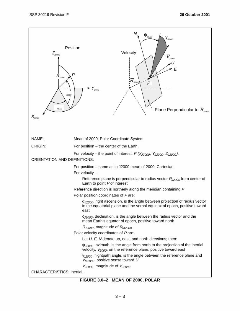


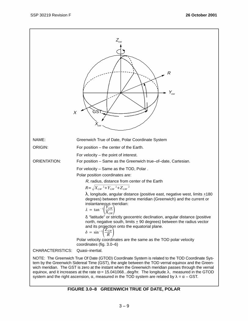
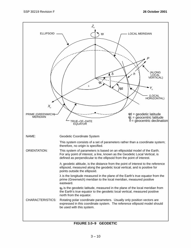
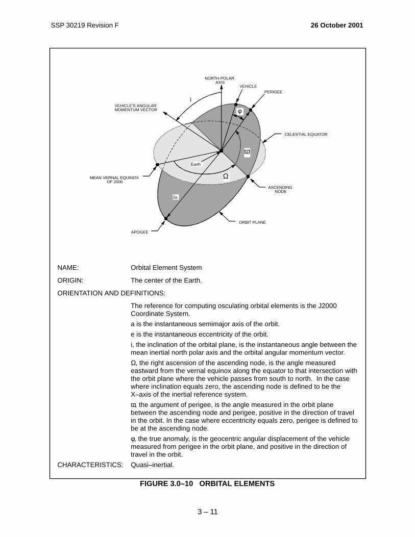


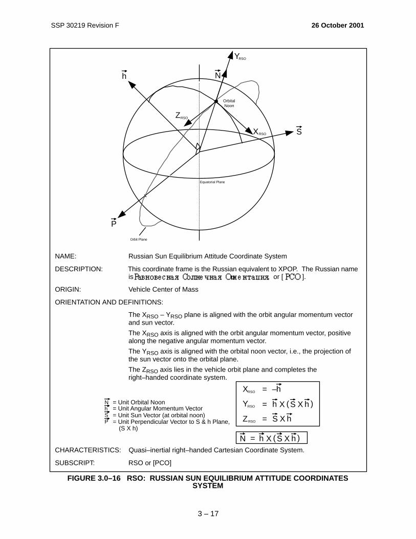


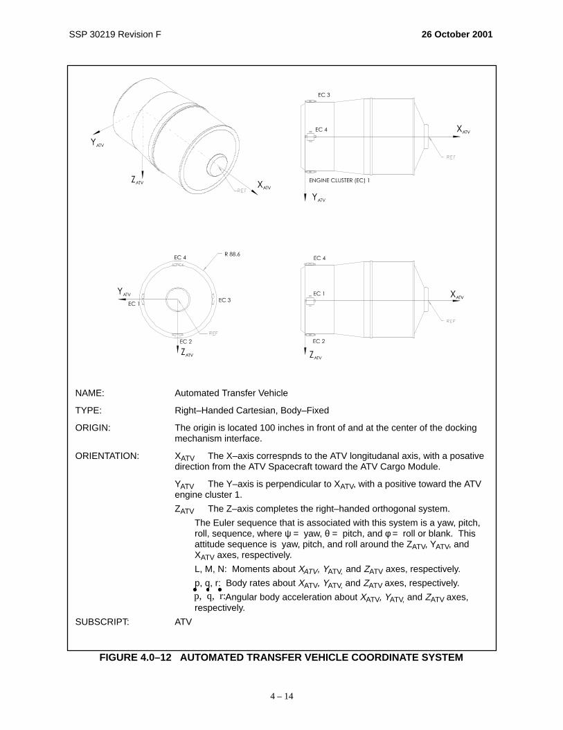


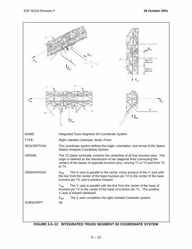


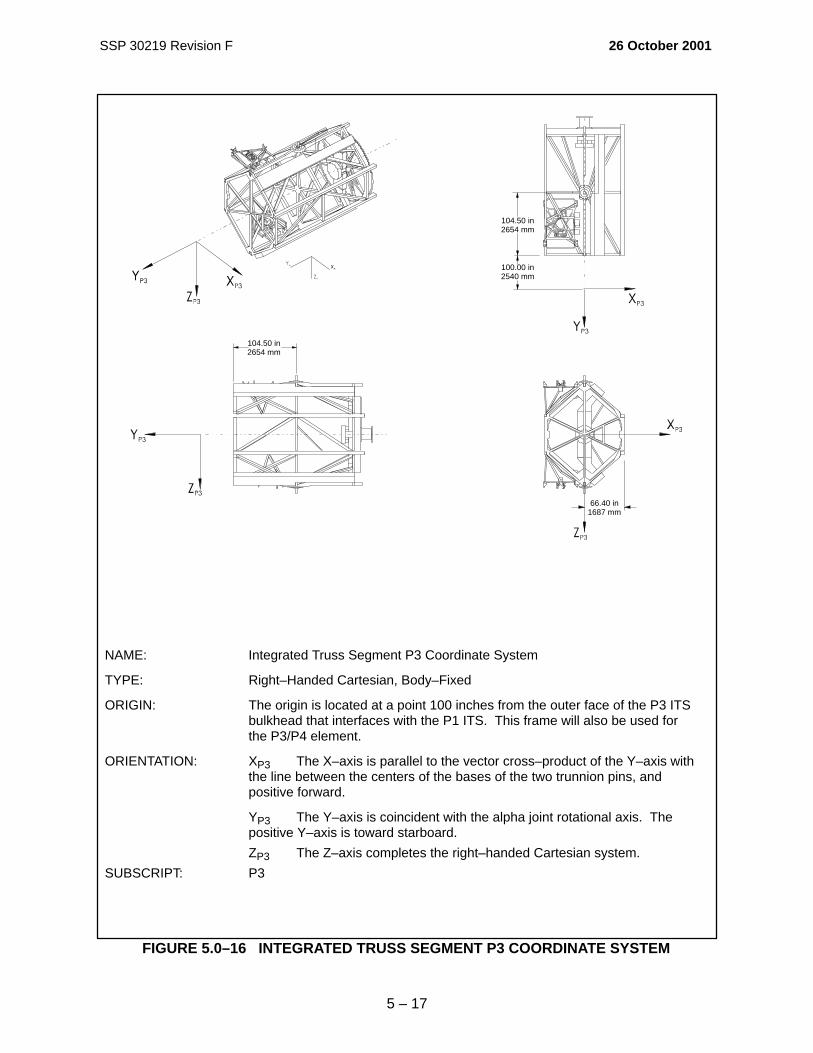


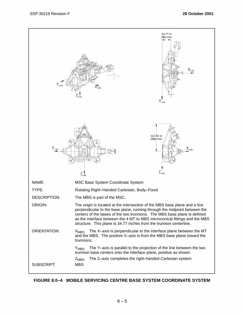
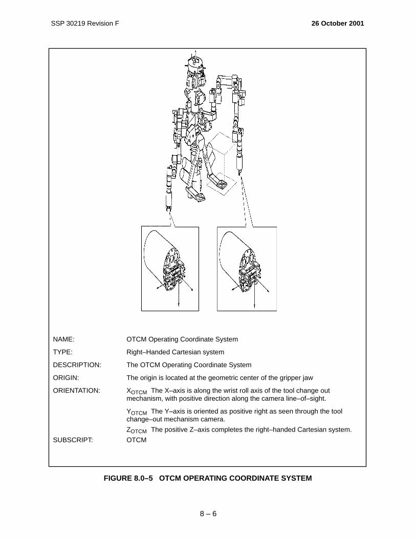


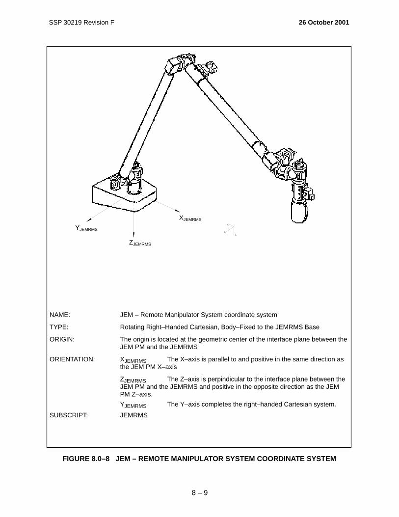


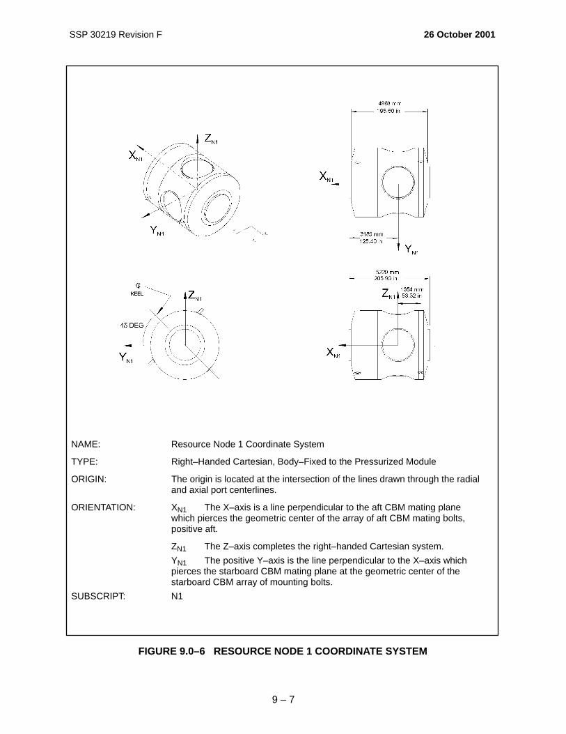


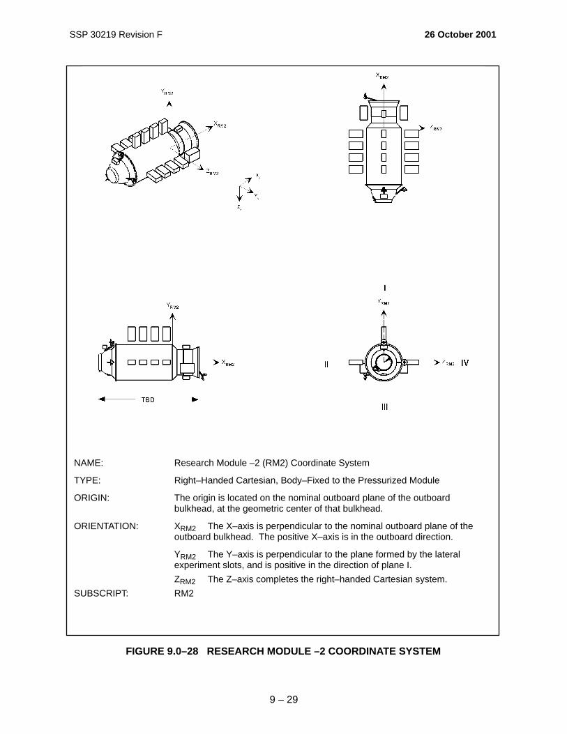


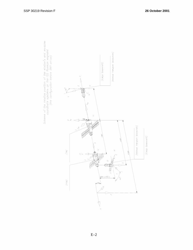
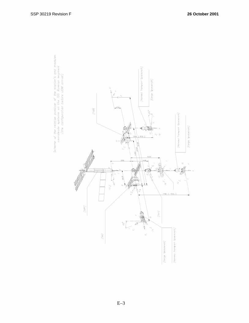


![Cartrigde Couplers for ! 5 @ 8 O Electronic Cooling CO-series · Type DN. Cv Cv-value . A > 5 4 8 = 5 = 8 O [/N] connection force unpressurized. A > 5 4 8 = 5 = 8 8 Max. side-to-side](https://static.documents.pub/doc/80x56/5f90e9d184b6960479188ae3/cartrigde-couplers-for-5-8-o-electronic-cooling-co-series-type-dn-cv-cv-value.jpg)


