Diez 1 34 th Annual Small Satellite Conference SSC20-P1-09 SpaceVPX/FMC for Electronics Standardization and Modularity in High-Performance SmallSat Architectures Rodrigo Diez, Facundo Jorge Novo Space Hawthorne, CA; 617-830-4764 [email protected]Kerri Cahoy Dep. Aeronautics and Astronautics, MIT 77 Mass. Ave., Cambridge, MA 02139; 650-814-8148 [email protected]Patrick Collier VITA 78 (SpaceVPX) Working Group Chair Melbourne, FL; 505-235-2817 [email protected]ABSTRACT A general-purpose architecture combining the SpaceVPX and FMC open standards is proposed for future high- performance space systems in the 10 to 500 kg range. This modular architecture promotes the reuse of components across subsystems reducing mission risk, cost, and development time. The data throughput of the selected standards supports modern high-bandwidth payloads such as high-resolution cameras, communication systems, and synthetic- aperture radars. This architecture also favors a high level of integration of payload and avionics subsystems enabling high levels of reliability and low SWaP. The small SpaceVPX 3U form factor (100 mm wide) enables high- performance systems with low volume, but the limited User Defined (UD) pins to the Backplane can become a bottleneck in the system. The introduction of the FMC standard makes it possible to circumvent the UD pin limitations and implement Input/Output (IO) mezzanine modules as an alternative to Rear Transition Modules (RTMs). The FMC can also be used for more complex functionalities to provide an extra layer of configurability to the system, implementing functions such as mass storage and digitization. When the FMC is not used for IO and more UD interfaces are needed, unused pins can be repurposed and routed through the Backplane to an IO board. INTRODUCTION Despite the proliferation of small CubeSats, there are some applications for which slightly bigger satellites are necessary. Many future missions will be in the 10 kg to 500 kg range 1 , where more size, weight, and power (SWaP) are allocated for the payload. However, the cost and long development cycles of the traditional space missions must be significantly reduced over the coming years for the new commercial and defense applications to succeed. While electronics for small CubeSats heavily rely on standards, such as the PC-104, the 10+ kg segment still needs modular and standard components capable of exchanging data at high rates (>100 Gbit/s) to satisfy demanding applications such as imaging radar, real- time video, and broadband communications. Due to the lack of off the shelf standard products for this satellite segment, companies are forced to develop custom high- performance systems. The use of standards opens the market to different vendors and allows the reuse of hardware across different systems, resulting in savings due to medium-scale production, enabling companies to significantly reduce their development time, cost, and risk. It is desirable to push for improvements on existing space applications implementing the Compact PCI (cPCI) standard, whose reliability and performance suffer from the limitations characteristic of a parallel bus. Due to the bus configuration, failures are propagated between modules, and simultaneous communications between components connected in the same Backplane are not allowed. Modern standards for space implement serial interfaces (SERDES) to support
Transcript
Diez 1 34th Annual Small Satellite Conference
SSC20-P1-09
SpaceVPX/FMC for Electronics Standardization and Modularity in High-Performance SmallSat Architectures
A general-purpose architecture combining the SpaceVPX and FMC open standards is proposed for future high-performance space systems in the 10 to 500 kg range. This modular architecture promotes the reuse of components across subsystems reducing mission risk, cost, and development time. The data throughput of the selected standards supports modern high-bandwidth payloads such as high-resolution cameras, communication systems, and synthetic-aperture radars. This architecture also favors a high level of integration of payload and avionics subsystems enabling high levels of reliability and low SWaP. The small SpaceVPX 3U form factor (100 mm wide) enables high-performance systems with low volume, but the limited User Defined (UD) pins to the Backplane can become a bottleneck in the system. The introduction of the FMC standard makes it possible to circumvent the UD pin limitations and implement Input/Output (IO) mezzanine modules as an alternative to Rear Transition Modules (RTMs). The FMC can also be used for more complex functionalities to provide an extra layer of configurability to the system, implementing functions such as mass storage and digitization. When the FMC is not used for IO and more UD interfaces are needed, unused pins can be repurposed and routed through the Backplane to an IO board.
INTRODUCTION
Despite the proliferation of small CubeSats, there are some applications for which slightly bigger satellites are necessary. Many future missions will be in the 10 kg to 500 kg range1, where more size, weight, and power (SWaP) are allocated for the payload. However, the cost and long development cycles of the traditional space missions must be significantly reduced over the coming years for the new commercial and defense applications to succeed.
While electronics for small CubeSats heavily rely on standards, such as the PC-104, the 10+ kg segment still needs modular and standard components capable of exchanging data at high rates (>100 Gbit/s) to satisfy demanding applications such as imaging radar, real-time video, and broadband communications. Due to the
lack of off the shelf standard products for this satellite segment, companies are forced to develop custom high-performance systems. The use of standards opens the market to different vendors and allows the reuse of hardware across different systems, resulting in savings due to medium-scale production, enabling companies to significantly reduce their development time, cost, and risk.
It is desirable to push for improvements on existing space applications implementing the Compact PCI (cPCI) standard, whose reliability and performance suffer from the limitations characteristic of a parallel bus. Due to the bus configuration, failures are propagated between modules, and simultaneous communications between components connected in the same Backplane are not allowed. Modern standards for space implement serial interfaces (SERDES) to support
Diez 2 34th Annual Small Satellite Conference
the reliability and throughput required for state-of-the-art applications. There are two candidates being proposed at the moment: cPCI Serial Space2 in Europe and VITA 78 SpaceVPX3 in the US. SpaceVPX leverages VITA 65 OpenVPX4 and adds some specifications to increase reliability. The SpaceVPX has already undergone improvements as a result of the feedback from adopters and users5, resulting in an attractive and maturing standard with a growing user base.
In this work, we describe an approach using the SpaceVPX standard in combination with the VITA 57.1 FMC6 (Field Programable Gate Array - FPGA Mezzanine Card standard). FMC is widely used in the defense industry to provide different IO capabilities to the same baseboard. Additionally, the FMC standard offers the flexibility to add mission-specific hardware to the system, limiting the non-recurring engineering (NRE) to the mezzanine card. By discussing three example case studies of a payload subsystem, an avionics subsystem, and a subsystem combining both avionics and payload in the same mechanical box, we show how the combination of SpaceVPX and FMC provides an overall advantage for high-performance, high-reliability small satellite applications.
ARCHITECTURE
Designing an embedded computing system for space requires a solution that withstands the extreme vibrations of liftoff and handles the extreme temperatures, background radiation, and other harsh conditions of space. VITA 78 SpaceVPX leverages the VITA 65 OpenVPX Backplane standard for space-capable systems, giving top priority to reliability.
In VITA 78, every connection is point-to-point; there are no buses in the system, limiting the propagation of failures through many components. In addition, modules and connections between modules are redundant, deriving in systems with no single points of failure. Redundancy definitions in the standard include dual-redundant power units and power distribution lines, dual-redundant modules (cards), dual-redundant Utility, Control, and Data Planes (point-to-point cross-strapped), and card-level reset and power control.
The modularity defined in the SpaceVPX standard is adequate for the conceptualization of different applications, though the division in sub-functions increases the SWaP and cost of the systems. Combining multiple functions into single modules reduces SWaP, but decreases the flexibility of each module. The number of applications, and hence, the space heritage of the products, would be reduced if the modules are not flexible enough.
To reduce SWaP and simultaneously increase both flexibility and modularity, we propose an architecture combining the SpaceVPX standard with the VITA 57 FMC standard. This combination will allow rapid deployment with minimum redesigns.
SpaceVPX defines two form factors: 3U cards are 100 mm wide and 6U cards are 200 mm wide (not to be confused with the U terminology used in CubeSats). The 3U form factor allows for small SWaP systems. Our initial estimations show that the combination of custom heatsinks with wedge locks provide ample thermal dissipation and does not constrain the processing power of the board for most applications. The main issue with 3U systems is the number of UD pins available in the system, which is analyzed in the next section. Figure 1 shows a 3U SpaceVPX board with the connector defined in the FMC standard.
Figure 1: 3U 160 mm SpaceVPX Card with FMC Connector, courtesy of Novo Space
There are other standards conceived to bring flexibility to baseboards, such as the PMC and XMC. However, they both use the PCI standard, which is not part of the SpaceVPX definition. The SpaceVPX standard makes use of the serial Rapid IO (sRIO) and SpaceWire for its Data and Control Planes, respectively. Going from the protocol defined in the SpaceVPX standard (sRIO / SpaceWire) to the one required for these mezzanine cards (PCI/PCIe) would require many logic resources in an FPGA, clock cycles in a microprocessor, or an Application-Specific Integrated Circuit (ASIC). Additionally, the FMC mezzanine modules use a smaller form factor than the other two standards. Finally, FMC cards support the high-speed SERDES needed for ADCs and DACs with JESD204B7 interface and other modern devices. Examples of FMC cards are:
● Mass memory ● High-speed ADC and DAC
Diez 3 34th Annual Small Satellite Conference
● High-throughput interfaces like Camera Link, SpaceWire, or SpaceFibre
● Low-speed control interfaces like MIL-STD-1553-B, UART or CAN
The last piece of the puzzle is the Backplane, which provides fast interconnect between SpaceVPX cards through high-speed serial links. SpaceVPX defines several standard Backplanes to support different number of slots and topologies.
Both SpaceVPX and FMC standards make use of the JTAG standard (named after the Joint Test Action Group which codified it) for verification, on-chip instrumentation, and configuration. Each JTAG-enabled component in a subsystem can be connected through a JTAG network as shown below, making troubleshooting possible even after integration, as every module in the system can be reached through a single external connector.
Figure 2: JTAG System Network
Both, VITA 78 and VITA 57 support serial data interfaces: at least 8 lanes in most 3U slot profiles under VITA 78 and, in the case of VITA 57, 10 lanes when using the High Pin Count (HPC) connector. The combination of these high-throughput interfaces with high-performance electronics will favor a higher level of integration, where complex tasks are performed not by different subsystems in individual mechanical boxes but in modules connected through a high-throughput Backplane, to enable high levels of reliability and low SWaP.
WORKAROUNDS FOR SERIAL BACKPLANES AND SLOT PROFILES
Like most modern standards, SpaceVPX is point-to-point and serial. The SpaceVPX standard defines many serial links per node (SpaceVPX board), supporting simultaneous communications between different nodes in the system, and between one node and many other nodes through the use of multiple serial links. These multiple links also add redundant paths between two
nodes, either via direct connection of more than one link between two nodes or via indirect connection through a third node.
The SpaceVPX standard inherits the OpenVPX definition of Pipes, a physical aggregation of differential pairs used for a common function. The SpaceVPX defines Ultra-Thin Pipe (UTP), Thin Pipe (TP), Fat Pipe (FP), Double Fat Pipe (DFP), Triple Fat Pipe (TFP), Quad Fat Pipe (QFP), and Octal Fat Pipe (OFP), comprising 2, 4, 8, 16, 24, 32, 64 differential pairs respectively. These are full duplex interfaces (one pair Tx, another Rx); each pair of differential signals will be referred as a lane. A Pipe or lane are not characterized by the protocol used on it.
The standard also defines the concept of Plane, a physical and logical interconnection path between elements of a system used for the transfer of information between elements. The standard defines a Control Plane dedicated to application software control traffic, a Data Plane used for application and external data traffic, an Expansion Plane dedicated to communication between a logical controlling system element and a separate, but logically adjunct, system resource, and a Utility Plane dedicated to common system services and/or utilities. Each Plane is composed of one or more Pipes, except for the Utility Plane which is low speed.
Thanks to the serial links, the Data Plane supports multiple topologies, including mesh, star, and double star. This brings a lot of flexibility to the system and allows for optimizing the system for performance, reliability, or both. However, this also means that the topologies of two similar systems are significantly different. For example, adding one extra node in a bus does not change the architecture significantly (both Backplanes are similar), but adding a node in a mesh Backplane can completely change the connections between several components.
There are several modules defined in the standard, including: Controller, Payload, Peripheral, and Switch. At bare minimum, a SpaceVPX system consists of one controller and one payload or peripheral. Figure 3 shows the pins definition for two widely used 3U profiles:
Diez 4 34th Annual Small Satellite Conference
Figure 3: System Controller profile SLT3-CON-2F8T-14.6.1 (left), Payload Profile SLT3-PAY-
2F1Q2T-14.2.1 (center), References (right).
It is worth noting that the word “Payload” in the standard refers to its role in the SpaceVPX system, independently of the role that the SpaceVPX system performs on the satellite (payload subsystem or bus subsystem). In this document, “Payload” with the first letter in upper case refers to the SpaceVPX module and “payload” with lower case letters refers to the subsystem. Similarly, the word “Controller” refers to the System Controller module defined in the SpaceVPX standard independently of its use in different subsystems.
These two slot profiles specify the way the pins in the 3U SpaceVPX connector are assigned to the different Planes defined in the standard. For example, the SLT3-CON-2F8T-14.6.1 profile has 8 TPs (4 differential pairs each) to control the activity in the subsystem through the Control Plane and the SLT3-PAY-2F1Q2T-14.2.1 has only 2 Pipes for redundancy. Both profiles have only 2 Data Plane FPs (8 differential pairs each). In addition, the SLT3-CON-2F8T-14.6.1 profile drives the signals that are connected to the Space Utility Management module (SpaceUM), such as clocks and resets of the Utility Plane.
As shown, there are not many UD pins in the 3U form factor. In the Payload profile, there are enough UD pins for most applications but in the Controller profile, there are only a few. This can be an issue when a system needs a dumb peripheral board or an RTM module on the back of the Backplane connected through these UD pins to the SpaceVPX module. This is the case when cycle accurate synchronism signals are needed or when there is no IO expansion device in the peripheral or RTM module. This could prevent the Controller of the chassis from implementing any interface beyond the
ones defined in the standard, becoming a roadblock in most systems.
3U profiles are preferred in order to reduce SWaP; however, as described in this section, there are two issues: small number of User Defined pins and limited standard Backplanes. The following are recommendations that could be used to address these two concerns:
#1: Be open to custom Backplanes: SpaceVPX defines some standard topologies, but they are unlikely to support your specific application, especially if a heavily optimized system is desired, where every pin counts. Additionally, there will always be a good reason to request changes in the Backplane design of each new system, whether it is because of new interfaces, different Control or Data Plane topology, number of redundancies, bandwidth (number and type of Pipes) between any two components, etc.
#2: Further slim down: When the SWaP available is low and the risk profile allows it, single string systems should be used (with redundancy added at box level instead - or not!). These are some small systems with only a few slots that can still benefit from the SpaceVPX standard (even though the system is not technically compliant, they can leverage complaint boards). These custom-made Backplane systems rely on repurposing pins and simplifying the Utility Plane and power distribution to avoid the implementation of the SpaceUM module and hence reduce SWaP even further (see Future Work).
#3: Use boards capable of repurposing the Control Plane signals: If you repurpose as UD every control line defined in the profile but not used in your system, you gain more capacity to support more custom interfaces. Boards supporting this feature frequently use FPGA or System on Chip (SoC) devices capable of reprograming their functionality and the logic level of the pins connected to the Backplane.
#4: Use boards capable of splitting the Pipes of the Data Plane to have more options: Sometimes having an optimal architecture means that you need to split a FP into 4 UTP to get the mesh topology you want, or to get extra resiliency in case a slot fails. Having configurable hardware that can accommodate such configurations will open more design options and increase the possibility of hardware reuse in different subsystem and missions. Similar to recommendation #3, make sure the device and firmware implementing these interfaces supports such flexibility.
#5: Use FMCs to circumvent the limited number of UD pins: The lack of UD pins in the SpaceVPX connector
Diez 5 34th Annual Small Satellite Conference
is a significant bottleneck to the use of RTMs. If HPC FMC slots are used, this limitation is reduced significantly as there are 160 IO and 10 SERDES available.
#6: Bear in mind that the FMC mezzanine card can sometimes be used to implement other functionality like storage, co-processing, or digitization. In such cases, having custom IOs in the FMC is not a real option because of the available physical space for additional connectors on the bezel or because the same FMC card is reused in different applications and allocating all IO capabilities for each use case is not possible. (see next recommendation)
#7: Lastly, if needed, add an IO slot to the system: Sometimes you lack the real state to implement all the glue logic needed, or you need to share a single sensor between redundant controllers but it lacks redundant interfaces. Whichever the reason is, an IO board can help you address those issues as it can provide a simple interface with more room for glue logic and panel real state for your external interfaces. The drawback of this approach is having to deal with the limited UD pins or be forced to have a complex device to provide IO expansion to your system (see recommendation #3). The IO board is also well suited to solve cross-strapping between dual redundant SpaceVPX modules and single string external subsystems.
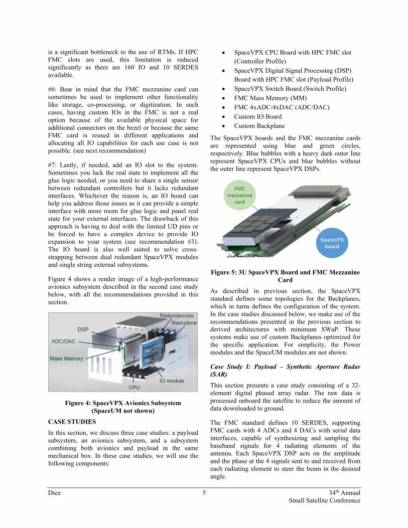
Figure 4 shows a render image of a high-performance avionics subsystem described in the second case study below, with all the recommendations provided in this section.
Figure 4: SpaceVPX Avionics Subsystem (SpaceUM not shown)
CASE STUDIES
In this section, we discuss three case studies: a payload subsystem, an avionics subsystem, and a subsystem combining both avionics and payload in the same mechanical box. In these case studies, we will use the following components:
SpaceVPX CPU Board with HPC FMC slot
(Controller Profile)
SpaceVPX Digital Signal Processing (DSP)
Board with HPC FMC slot (Payload Profile)
SpaceVPX Switch Board (Switch Profile)
FMC Mass Memory (MM)
FMC 4xADC/4xDAC (ADC/DAC)
Custom IO Board
Custom Backplane
The SpaceVPX boards and the FMC mezzanine cards are represented using blue and green circles, respectively. Blue bubbles with a heavy dark outer line represent SpaceVPX CPUs and blue bubbles without the outer line represent SpaceVPX DSPs.
Figure 5: 3U SpaceVPX Board and FMC Mezzanine Card
As described in previous section, the SpaceVPX standard defines some topologies for the Backplanes, which in turns defines the configuration of the system. In the case studies discussed below, we make use of the recommendations presented in the previous section to derived architectures with minimum SWaP. These systems make use of custom Backplanes optimized for the specific application. For simplicity, the Power modules and the SpaceUM modules are not shown.
Case Study I: Payload – Synthetic Aperture Radar (SAR)
This section presents a case study consisting of a 32-element digital phased array radar. The raw data is processed onboard the satellite to reduce the amount of data downloaded to ground.
The FMC standard defines 10 SERDES, supporting FMC cards with 4 ADCs and 4 DACs with serial data interfaces, capable of synthesizing and sampling the baseband signals for 4 radiating elements of the antenna. Each SpaceVPX DSP acts on the amplitude and the phase at the 4 signals sent to and received from each radiating element to steer the beam in the desired angle.
Diez 6 34th Annual Small Satellite Conference
The flexibility of the CPU is key to implement the star topology selected for this application. The CPU must be able to split the redundant FPs (4 lanes each) as 8 independent UTPs (1 lane). This way the data from the ADCs is preprocessed in the DSP and sent to the CPU for data formatting adding time stamps, channel identifier, redundancy information, etc. The Formatter implemented in a SpaceVPX CPU reroutes the data to the corresponding DSP to perform the next step in the processing chain. In addition to formatting data, the CPU implements the functionality of the SpaceVPX System Controller.
The local memory on the DSP board buffers the data transferred between the FMC and the SpaceVPX interface. If the duty cycle of the conversion windows used to sample the echo signal and the sampling frequency are high, then the serial data interface between each DSP module and the CPU module will not support the data rate generated by the four ADCs on the FMC card. In that case, the unused serial data interfaces available on each DSP module can be used to connect the DSP modules to each other, resulting in a mesh topology with a distributed Data Switch.
Figure 6: Synthetic-Aperture Radar with Star Topology Backplane
The Formatter module implements the last processing layer, including image compression and storage. The Mass Memory FMC (MM) securely stores formatted data, which are retrieved and sent to the downlink through the frontal connectors in the CPU board when the satellite is in view of the ground station. The CPU receives commands from and sends telemetry data to the Control and Data Handling (C&DH) subsystem. It worth noting that under the SpaceVPX standard there
should be redundancy for compliance. The architecture presented in this section is an unorthodox use of the standard.
If operation in degraded mode is accepted allowing up to one DSP module to fail, then the only single point of failure in the system is the CPU. Adding a second CPU (Formatter) to the system makes it more compliant with the standard and reduces the probability of failure significantly.
Figure 7: Synthetic-Aperture Radar with Star Topology Backplane and Redundant Controller
This system is not fully compliant with the standard either because the DSP modules are not fully redundant. However, though the systems and Backplanes are not compliant, every SpaceVPX and FMC card is fully compliant with the corresponding standard.
Case Study II: Avionics for Small Satellites
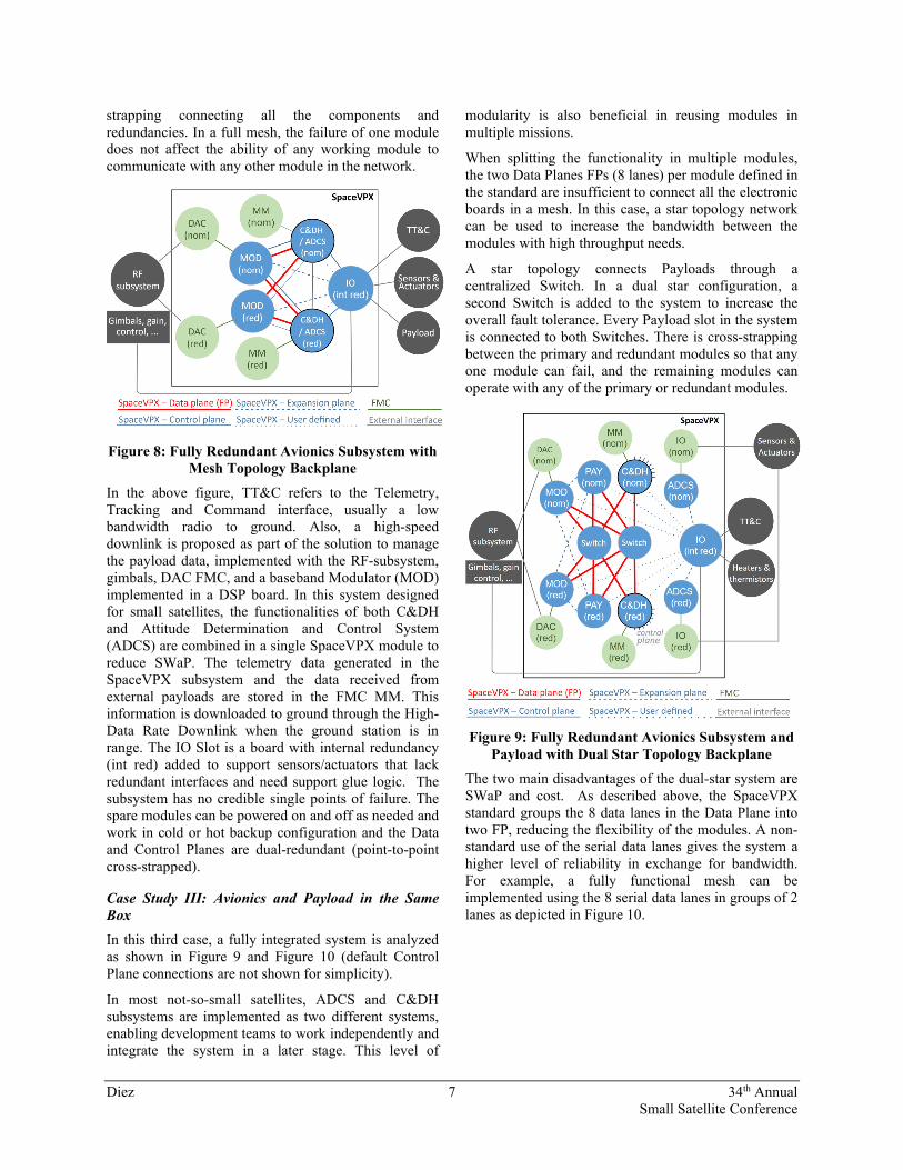
The avionics subsystem implements many critical functions. The risk tolerance is low because the subsystem is not allowed to fail. For this reason, a fully redundant system in mesh configuration is presented in this section. A mesh topology connects each slot directly to every other slot without the use of a centralized Switch slot, although in some cases the Switch can be embedded in the Payload modules.
As shown in Figure 8, each component in the subsystem has its own redundancy with full cross-
Diez 7 34th Annual Small Satellite Conference
strapping connecting all the components and redundancies. In a full mesh, the failure of one module does not affect the ability of any working module to communicate with any other module in the network.
Figure 8: Fully Redundant Avionics Subsystem with Mesh Topology Backplane
In the above figure, TT&C refers to the Telemetry, Tracking and Command interface, usually a low bandwidth radio to ground. Also, a high-speed downlink is proposed as part of the solution to manage the payload data, implemented with the RF-subsystem, gimbals, DAC FMC, and a baseband Modulator (MOD) implemented in a DSP board. In this system designed for small satellites, the functionalities of both C&DH and Attitude Determination and Control System (ADCS) are combined in a single SpaceVPX module to reduce SWaP. The telemetry data generated in the SpaceVPX subsystem and the data received from external payloads are stored in the FMC MM. This information is downloaded to ground through the High-Data Rate Downlink when the ground station is in range. The IO Slot is a board with internal redundancy (int red) added to support sensors/actuators that lack redundant interfaces and need support glue logic. The subsystem has no credible single points of failure. The spare modules can be powered on and off as needed and work in cold or hot backup configuration and the Data and Control Planes are dual-redundant (point-to-point cross-strapped).
Case Study III: Avionics and Payload in the Same Box
In this third case, a fully integrated system is analyzed as shown in Figure 9 and Figure 10 (default Control Plane connections are not shown for simplicity).
In most not-so-small satellites, ADCS and C&DH subsystems are implemented as two different systems, enabling development teams to work independently and integrate the system in a later stage. This level of
modularity is also beneficial in reusing modules in multiple missions.
When splitting the functionality in multiple modules, the two Data Planes FPs (8 lanes) per module defined in the standard are insufficient to connect all the electronic boards in a mesh. In this case, a star topology network can be used to increase the bandwidth between the modules with high throughput needs.
A star topology connects Payloads through a centralized Switch. In a dual star configuration, a second Switch is added to the system to increase the overall fault tolerance. Every Payload slot in the system is connected to both Switches. There is cross-strapping between the primary and redundant modules so that any one module can fail, and the remaining modules can operate with any of the primary or redundant modules.
Figure 9: Fully Redundant Avionics Subsystem and Payload with Dual Star Topology Backplane
The two main disadvantages of the dual-star system are SWaP and cost. As described above, the SpaceVPX standard groups the 8 data lanes in the Data Plane into two FP, reducing the flexibility of the modules. A non-standard use of the serial data lanes gives the system a higher level of reliability in exchange for bandwidth. For example, a fully functional mesh can be implemented using the 8 serial data lanes in groups of 2 lanes as depicted in Figure 10.
Diez 8 34th Annual Small Satellite Conference
Figure 10: Fully Redundant Avionics Subsystem and Payload with Mesh Topology Backplane.
The bold red line between C&DH and the Modulator represents two serial data lanes used to download high volumes of data stored in the MM during periods of no visibility of the ground station.
FUTURE WORK
The Data, Control, and Expansion Planes are significant portions of the architecture of any SpaceVPX system. However, there are other aspects of the system with high impact on the overall reliability of the solution and its weight and size: The Space Utility Management module (UM module) and the Power Modules. There are currently some efforts5 to address this increase in size and weight, though there is no comprehensive solution yet. Future work will study SpaceVPX compliant systems optimized for size and weight, which can be challenging in small systems.
REFERENCES
1. Werner, D., “Smallsat builders admit a little bigger might be a little better”, http://spacenews.com/smallsat-builders-admit-a-little-bigger-might-be-better/#sthash.6QuHG7of.dpuf, February 2017
2. “PICMG CPCI-S.1 R1.0 CompactPCI Serial for Space”, August 2017
3. “ANSI/VITA 78.00-2015 SpaceVPX System”, April 2015
4. “ANSI/VITA 65.0-2017 OpenVPX System Standard”, August 2017
5. Marshall, J., Collier, P., and Kimmery, C., “Improving a Successful Space Electronics High
Performance Fabric-Based Standard”, 2019 IEEE Aerospace Conference, March 2019
6. “ANSI/VITA 57.1 FPGA Mezzanine Card (FMC) Standard”, July 2008 (Revised February 2010)
7. “JEDEC Solid State Technology Association. JESD204B, Serial Interface for Data Converters”, April 2008