API SPECs4F 95 0732270 0543268 465 m Specification for Drilling and Well Servicing Structures API SPECIFICATION 4F SECOND EDITION, JUNE 1, 1995 American Petroleum Institute 1220 L Street, Northwest Washington, D.C. 20005 P No reproduction or networking permitted without license from IHS --`,,-`-`,,`,,`,`,,`--- //^:^^#^~^^"~~:~"~$$"~$^"#:*~:$"^^#:^~~^$:^~~":^*#^#"\\
Transcript
API SPECs4F 95 0732270 0543268 465 m
Specification for Drilling and Well Servicing Structures
API SPECIFICATION 4F SECOND EDITION, JUNE 1, 1995
American Petroleum Institute 1220 L Street, Northwest Washington, D.C. 20005 P
Copyright American Petroleum Institute Provided by IHS under license with API
Not for ResaleNo reproduction or networking permitted without license from IHS
--`,,-`-`,,`,,`,`,,`---
//^:^
^#^~
^^"~
~:~"
~$$"
~$^"
#:*~
:$"^
^#:^
~~^$
:^~~
":^*#
^#"\\
A P I SPECa4F 75 0732290 0543267 3 T L m
Specification for Drilling and Well Servicing Structures
Exploration and Production Department
API SPECIFICATION 4F SECOND EDITION, JUNE 1, 1995
American Petroleum Institute
Copyright American Petroleum Institute Provided by IHS under license with API
Not for ResaleNo reproduction or networking permitted without license from IHS
--`,,-`-`,,`,,`,`,,`---
//^:^
^#^~
^^"~
~:~"
~$$"
~$^"
#:*~
:$"^
^#:^
~~^$
:^~~
":^*#
^#"\\
API SPEC*4F 95 m 0732290 0543270 013 m
SPECIAL NOTES API publications necessarily address problems of a general nature. With respect to par-
ticular circumstances, local, state, and federal laws and regulations should be reviewed. API is not undertaking to meet the duties of employers, manufacturers, or suppliers to
warn and properly train and equip their employees, and others exposed, concerning health and safety risks and precautions, nor undertaking their obligations under local, state, or federal laws.
Information concerning safety and health risks and proper precautions with respect to particular materials and conditions should be obtained from the employer, the manufacturer or supplier of that material, or the material safety data sheet.
Nothing contained in any API publication is to be construed as granting any right, by im- plication or otherwise, for the manufacture, sale, or use of any method, apparatus, or prod- uct covered by letters patent. Neither should anything contained in the publication be construed as insuring anyone against liability for infringement of letters patent.
Generally, API standards are reviewed and revised, reaffirmed, or withdiawn at least ev- ery five years. Sometimes a one-time extension of up to two years will be added to this re- view cycle. This publication will no longer be in effect five years after its publication date as an operative API standard or, where an extension has been granted, upon republication. Status of the publication can be ascertained from the API Authoring Department [telephone (214) 953-1 1011, A catalog of API publications and materials is published annually and up- dated quarterly by API, 1220 L Street, N.W., Washington, D.C. 20005.
This document was produced under API standardization procedures that ensure appro- priate notification and participation in the developmental process and is designated as an API standard. Questions concerning the interpretation of the content of this standard or comments and questions concerning the procedures under which this standard was devel- oped should be directed in writing to the director of the Exploration and Production Depart- ment, American Petroleum Institute, 700 North Pearl, Suite 1840, Dallas, Texas 75201. Requests for permission to reproduce or translate all or any part of the material pbblished herein should also be addressed to the director.
API publications may be used by anyone desiring to do so. Every effort has been made by the Institute to assure the accuracy and reliability of the data contained in them; however, the Institute makes no representation, warranty, or guarantee in connection with this pub- lication and hereby expressly disclaims any liability or responsibility for loss or damage re- sulting from its use or for the violation of any federal, state, or municipal regulation with which this publication may conflict.
API standards are published to facilitate the broad availability of proven, sound engineer- ing and operating practices. These standards are not intended to obviate the need for applying sound engineering judgment regarding when and where these standards should be utilized. The formulation and publication of API standards is not intended in any way to inhibit anyone from using any other practices.
Any manufacturer marking equipment or materials in conformance with the marking re- quirements of an API standard is solely responsible for complying with all the applicable requirements of that standard. AF'I does not represent, warrant, or guarantee that such prod- ucts do in fact conform to the applicable API standard.
Copyright O 1994 American Petroleum Institute
Copyright American Petroleum Institute Provided by IHS under license with API
Not for ResaleNo reproduction or networking permitted without license from IHS
8.4 Material Manufacture ..................................................................................... 8.5 Bolts ...............................................................................................................
8.3 Material Qualification ....................................................................................
8.6 Wire Rope ...................................................................................................... WELDING REQUIREMENTS ............................................................................... 9.1 General ...........................................................................................................
iii
V
1 1 1 1
1 1 2
2
3 3 3 3 3
3 4 4 4 4 4 4 4
4 4 5 5 5 6 6 6 6
6 6 7 8 8 8
8 8 8 8 8 9 9
9 9
Copyright American Petroleum Institute Provided by IHS under license with API
Not for ResaleNo reproduction or networking permitted without license from IHS
--`,,-`-`,,`,,`,`,,`---
//^:^
^#^~
^^"~
~:~"
~$$"
~$^"
#:*~
:$"^
^#:^
~~^$
:^~~
":^*#
^#"\\
9.2 Welding Qualifications .................................................................................. 9 9.3 Written Documentation .................................................................................. 9 9.4 Control of Consumables ................................................................................ 9 9.5 Weld Properties .............................................................................................. 9 9.6 Post Weld Heat Treatment ............................................................................. 9 9.7 Quality Control Requirements ....................................................................... 9 9.8 Specific Requirement-Repair Welds ........................................................... 9
10 QUALITY CONTROL ............................................................................................ 10.1 General ........................................................................................................... 10.2 Quality Control Personnel Qualifications ...................................................... 10.3 Measuring and Test Equipment ..................................................................... 10.4 Non-Destructive Examination ........................................................................ 10.5 Dimensional Verification ............................................................................... 10.6 Workmanship and Finishing .......................................................................... 10.7 Purchaser's Inspection and Rejection ............................................................ 10.8 Testing ............................................................................................................ 10.9 Traceability ....................................................................................................
10 10 10 10 10 11 11 11 11 12
1 1 DOCUMENTATION ............................................................................................... 12 11.1 General ........................................................................................................... 12 1 1.2 Documentation to be Kept by the Manufacturer ............................................ 12 1 1.3 Documentation to be Delivered with the Equipment ..................................... 12
APPENDIX A-SUPPLEMENTARY REQUIREMENTS ........................................... 13 APPENDIX BCTANDARD DERRICKS .................................................................. 15 APPENDIX C-MARKING INSTRUCTIONS FOR API LICENSEES ..................... 17
Figures 1-Diagram of Projected Area .................................................................................. 7 B-1-Derrick Dimensions ......................................................................................... 15 B-2-Derrick Windows ............................................................................................. 15 B-3-Foundation Bolt Pattern for Derrick Leg ......................................................... 16
Tables 1-Height Coefficients. C,, ........................................................................................ 7 2"Conversion Values (For 0-50 Ft . Height) ............................................................. 7 A-1-Adjustment Factors for Sub-Size Impact Specimens ...................................... 13 B-1-Derrick Sizes and General Dimensions ........................................................... 15
Copyright American Petroleum Institute Provided by IHS under license with API
Not for ResaleNo reproduction or networking permitted without license from IHS
FOREWORD This specification is under the jurisdiction of the API Committee on Standardization of
The bar notations identify parts of this standard that have been changed from the previ-
This standard shall become effective on the date printed on the cover but may be used
Drilling and Servicing Equipment.
ous API edition.
voluntarily from the date of distribution.
V
Copyright American Petroleum Institute Provided by IHS under license with API
Not for ResaleNo reproduction or networking permitted without license from IHS
--`,,-`-`,,`,,`,`,,`---
//^:^
^#^~
^^"~
~:~"
~$$"
~$^"
#:*~
:$"^
^#:^
~~^$
:^~~
":^*#
^#"\\
Specification for Drilling and Well Servicing Structures
1 Scope This specification covers the design, manufacture, and use
of steel derricks, portable masts, crown block assemblies, and substructures suitable for drilling and servicing of wells. It includes stipulations for marking, inspection, standard ratings, design loading, and design specifications of the equipment. Definitions of commonly used terms are in- cluded in Section 3.
1.1 PURPOSE
1.1.1 The purpose of this specification is to provide suit- able structures for drilling and well servicing operations and to provide a uniform method of rating the structures for the petroleum industry. It is the intent that these speciJications be applied to all new designs of all standard derricks, spe- cial derricks, portable masts and substructures.
1.1.2 Products manufactured according to API Standards 4A, 4D, and 4E may not necessarily comply with all the re- quirements of this specification. It is the committee’s inten- tion that this standard be written to meet the requirements of present and future operating conditions, such as deeper drilling, offshore drilling from floating devices, and the effect of earthquakes, storms, and other adverse operating conditions.
1.1 -3 The standard is not a text book, but rather a guide by which the manufacturer and user will have a common under- standing of the capacities and ratings of the various struc- tures for dnlling and well servicing operations.
1.2 PRODUCT SPECIFICATION LEVELS
This specification establishes requirements for two prod- uct specification levels. These two PSL designations define different levels of technical and quality requirements. PSL 1 includes practices currently being implemented by a broad spectrum of the manufacturing industry. All the requirements of this specification are applicable to PSL 1 unless specifi- cally identified as PSL 2. PSL 2 includes all the requirements of PSL 1 plus additional practices currently being imple- mented by a broad spectrum of users.
1.3 SUPPLEMENTARY REQUIREMENTS
Supplementary requirements shall apply only when con- tractually specified by the Purchaser. Appendix A gives a number of standard supplementary requirements.
2 References 2.1 STANDARDS
2.1.1 General
This specification includes by reference, either in total or in part, other API and industry standards. The latest edition is defined as the edition in use at the Date of Manufacture. I 2.1.2 Requirements
Requirements of other standards included by reference in this specification are essential to the safety and interchange- ability of the equipment produced. I 2.1.3 Equivalent Standards
Other nationally or internationally recognized standards may be used provided it can be shown that they meet or ex- ceed the requirements of the reference standards herein. I 2.1.4 Standards References Note: The following list of standards is supplied for the convenience of the reader: only those portions of the standards listed below which are directly referenced in this specification are considered part of this specification. Documents (sub-tier) that are referenced by those standards are not consid- ered part of this specification.
AISC’ Specification for Structural Steel Buildings.
API RP 2A-WSD
Spec %A
Spec 8C
Spec 9A RP 9B
ASNT’ TC- 1 A
Recommended Practice for Planning, Designing, and Constructing Fixed Off- shore Platfoms Working Stress Design. Specification for Drilling and Production Hoisting Equipment. Specification for Drilling and Production Hoisting Equipment (PSL 1 and PSL 2). Specification for Wire Rope. Recommended Practice on Application, Care, and Use of Wire Rope for Oil Field Service.
Recommended Practice for Personnel Qualification and Certification in Non- Destructive Testing.
lAmerican Institute of Steel Construction. ’American Society for Nondestructive Testing, 171 1 Arlingate Lane, Box 285 18, Columbus, Ohio 43228-05 18.
1
Copyright American Petroleum Institute Provided by IHS under license with API
Not for ResaleNo reproduction or networking permitted without license from IHS
A578 Specification for Straight-Beam Ultra- sonic Examination of Plain and Clad Steel Plates for Special Applications.
AWS4 Dl .1 Structural Welding Code.
2.2 OTHER REFERENCES
A B S Rules for Building and Classing Offshore Drilling Units,
1991.
Principles of Naval Architecture, Vol. II, Rossel1 and Chap- man.
3 Definitions
apply: For the purposes of this standard, the following definitions
3.1 angle of roll or pitch: The angle of movement to one side from vertical.
3.2 critical components: A component which is neces- sary to maintain stability of a structure and resides within the primary load paths of the structure when the structure is loaded under the Design Loadings of Section 6.
3.3 critical weld: A weld joining critical components.
3.4 crown block assembly: The stationary sheave or block assembly installed at top of a derrick or mast.
3.5 date of manufacture: A date chosen by the manufac- turer occurring between the initiation of manufacture and the delivery to the customer.
3.6 derrick: A semipermanent structure of square or rect- angular cross-section having members that are latticed or trussed on all four sides. This unit must be assembled in the vertical or operation position, as it includes no erection mechanism. It may or may not be guyed.
3.7 design load: That force or combination of forces which a structure is designed to withstand without exceeding the allowable stress in any member.
3.8 dynamic loading: Loading imposed upon a structure as a result of motion as opposed to static loading.
3.9 erection load: The load produced in the mast and its supporting structure during the raising and lowering opera-
3American Society for Testing and Materials, 1916 Race Street, Philadel- phia, Pennsylvania 19103. 4American Welding Society, Incorporated, 550 Northwest LeJeune Road, Box 351040, Miami, Florida 33135. 5American Bureau of Shipping.
tion, or in the substructure during its raising and lowering operation.
3.1 O guide track and dollies: Equipment used to hold the traveling equipment in correct position in relation to the der- rick under the various operations. A retractable dolly shall also be able to move the traveling equipment horizontally be- tween the drilling position and the retracted position.
3.1 1 guy line: A wire rope with one end attached to the derrick or mast assembly and the other end attached to a suit- able anchor to provide structural andor lateral support for a mast under design loading conditions. I 3.12 guying pattern: A plan view showing the manufac- turer’s recommended locations and distance out to the anchors with respect to the wellhead.
3.13 height of derrick and mast without guy lines: The minimum clear vertical distance from the top of the working floor to the bottom of the crown block support beams.
3.14 height of mast with guy line: The minimum vertical distance from the ground to the bottom of the crown support beams.
3.15 impact loading: This loading results from sudden changes in the state of motion of components of the rig.
3.16 mast: A structural tower comprised of one or more sections assembled in a horizontal position near the ground and then raised to the operating position. If the unit contains two or more sections, it may be telescoped or unfolded dur- ing the erection procedure.
3.17 mast set-up distance: The distance from the center line of the well to a designated point on the mast structure defined by a manufacturer to assist in the setup of the rig.
3.18 maximum rated static hook load: A load composed of the weight of the traveling equipment and a static load ap- plied to the traveling block. It is the largest load that can be applied to the structure within the guidelines imposed by this specification with a specified number of lines strung to the traveling block and in the absence of pipe setback, sucker rod or wind loading. A designated location of the deadline anchor and drawworks is assumed.
3.19 maximum rated wind velocity: The maximum rated wind velocity is the wind velocity the derrick or the mast assembly is designed to resist against the force of the wind. I 3.20 nominal wire rope assembly strength: The wire rope’s nominal strength multiplied by the efficiency of the end attachment per API RF’ 9B. I 3.21 period of roll, pitch, or heave: The time for a com- plete cycle. I 3.22 pipe lean: The angle between the vertical and a typ- ical stand of pipe with the setback.
Copyright American Petroleum Institute Provided by IHS under license with API
Not for ResaleNo reproduction or networking permitted without license from IHS
--`,,-`-`,,`,,`,`,,`---
//^:^
^#^~
^^"~
~:~"
~$$"
~$^"
#:*~
:$"^
^#:^
~~^$
:^~~
":^*#
^#"\\
A P I SPEC*4F 75 m 0732290 0543276 5 3 1 m
SPECIFICATION FOR DRILLING AND WELL SERVICING STRUCTURES 3
I 3.23 product specification level: The level of material and process controls placed upon the primary load carrying components of the covered equipment.
3.24 racking platform: A platform located at a distance above the working floor for laterally supporting the upper end of racked pipe.
3.25 rated static rotary load: The maximum weight be- ing supported by the rotary table support beams.
3.26 rated setback load: The maximum weight of tubular goods which can be supported by the substructure in the set- back area.
3.27 rod board: A platform located at a distance above the working floor for supporting rods.
3.28 static hook load: See maximum rated static hook load.
3.29 substructure: Any structure through which hook I load, rotary load and/or setback load are transmitted.
4 Marking and Information 4.1 NAMEPLATE
Drilling and well servicing structures manufactured in ac- cordance with these specifications shall be identified by a nameplate bearing at least the information specified in the following paragraphs. Markings shall be either raised or stamped. The nameplate shall be securely affixed to the structure in a conspicuous place.
4.2 MAST AND DERRICK NAMEPLATE INFORMATION*
a. Manufacturer’s name. b. Manufacturer’s address.
d. Serial number. e. Height in feet. f. Maximum rated static hook load, in pounds, with guy lines if applicable, for stated number of lines to traveling
I c. Date of manufacture, including month and year.
1. Graph plotting maximum allowable static hook load ver- sus wind velocity as defined in 5.1.6 and 5.3.5. m. Mast setup distance for mast with guy lines. n. PSL 2, if applicable. I o. Supplementary requirement information as specified by the particular SR, if applicable. I 4.3 SUBSTRUCTURE NAMEPLATE
INFORMATION*
a. Manufacturer’s name. b. Manufacturer’s address. c. Date of manufacture, including month and year. I d. Serial number. e. Maximum rated static rotary capacity. f. Maximum rated pipe setback capacity. g. Maximum combined rated static rotary and rated setback capacity. h. API specification and edition of the API specification un- der which the structure was designed and manufactured. i. PSL 2, if applicable. I j. Supplementary requirement information as specified by the particular SR, if applicable. I 4.4 CROWN BLOCK ASSEMBLY NAMEPLATE
INFORMATION (Required only for crown block assemblies for use with derricks)*
a. Manufacturer’s name. b. Manufacturer’s address. c. Date of manufacture, including month and year. d. Serial number. e. Maximum rated static hook load. f. API Specification and edition of the API specification un- der which the structure was designed and manufactured. g. PSL 2, if applicable. h. Supplementary requirement information as specified by the particular SR, if applicable.
5 Standard Ratings block. Each structure shall be rated for the following applicable g. Maximum rated wind velocity, in knots, with guy lines if loading The structures shall be designed to meet applicable, with rated capacity of pipe racked . h. The MI specification and edition of the API specification
or exceed these conditions in accordance with applicable
under which the structure was designed and manufactured. specifications set herein. The following ratings do not in-
i. Manufacturer’s guying diagram-for structures as chde any allowance for impact. Acceleration, impact, set-
applicable. back and wind loads will reduce the rated static hook load
j. Following note shall appear on the nameplate: capacity.
CAUTION: ACCELERATION OR IMPACT, ALSO SET- *Users of this specification should note that there is no longer a requirement BACK AND WIND LOADS WILL REDUCE THE MM- for marking a product with the API monogram. The American Petroleum
IMUM RATED STATIC HOOK LOAD CAPACITY. Institute continues to license use of the monogram on products covered by this specification but it is administered by the quality program staff of the I Institute separately from the specification. The policy describing licensing
k a Manufacturer’s Load Distribution diagram* (May be and use of the monogram are contained in Appendix C herein. No other use placed in mast instructions.) of the monogram is permitted.
Copyright American Petroleum Institute Provided by IHS under license with API
Not for ResaleNo reproduction or networking permitted without license from IHS
5.1.1 Maximum rated static hook load for a specified number of lines strung to the traveling block.
5.1.2 Maximum rated wind velocity (knots) without full pipe setback.
5.1.3 Maximum rated wind velocity (knots) with full pipe setback.
5.1.4 Maximum number of stands and size of pipe in full setback.
5.1.5 Maximum rated gin pole capacity.
5.1.6 Rated static hook load for wind velocities varying from zero to maximum rated wind velocity with full rated setback and with maximum number of lines to the traveling block.
5.2 MAST WITH GUY LINES
5.2.1 Maximum rated static hook load capacity for a spec- ified number of lines strung to the traveling block and the manufacturer’s specified guying pattern.
5.2.2 Maximum rated wind velocity (knots) without pipe setback.
5.2.3 Maximum rated wind velocity (knots) with full pipe setback.
5.2.4 Maximum number of stands and size of pipe in full setback.
5.3 MAST WITHOUT GUY LINES
5.3.1 Maximum rated static hook load for a specified number of lines strung to the traveling block.
5.3.2 Maximum rated wind velocity (knots) without pipe setback.
5.3.3 Maximum rated wind velocity (knots) with full pipe setback.
5.3.4 Maximum number of stands and size of pipe in full setback.
5.3.5 Rated static hook load for wind velocities varying from zero to maximum rated wind velocity with full rated setback and with maximum number of lines to the traveling block.
5.4 MAST AND DERRICKS UNDER DYNAMIC CONDITIONS
5.4.1 Maximum rated static hook load for a specified number of lines to the traveling block.
5.4.2 Hook, load, wind load, vessel motions, and pipe set- back in combination with each other for the following:
a. Operating with partial setback. b. Running casing. c. Waiting on weather. d. Survival. e. In transit.
5.5 SUBSTRUCTURES
5.5.1 Maximum rated static hook load, if applicable.
5.5.2 Maximum rated pipe setback load.
5.5.3 Maximum rated static load on rotary table beams.
5.5.4 Maximum rated combined load of setback and rotary table beams.
5.6 SUBSTRUCTURE UNDER DYNAMIC CONDITIONS
5.6.1 Maximum rated static hook load.
5.6.2 Maximum rated pipe setback load.
5.6.3 Maximum rated load on rotary table beams.
5.6.4 Maximum rated combined load of setback and rotary table beams.
5.6.5 All ratings per 5.4.2.
5.7 CROWN BLOCK ASSEMBLY
Maximum rated static hook load for a specified number of lines strung to the traveling block.
6 Design Loading Each structure shall be designed for the following applica-
ble loading conditions. The structure shall be designed to meet or exceed these conditions in accordance with the applicable specifications set forth herein.
6.1 DERRICKSTATIONARY BASE
6.1.1 Operating loads (no wind loads) composed of the following loads in combination:
a. Maximum rated static hook load, in combination with fastline and deadline loads, for each applicable string up I condition. b. Dead load of demck assembly.
6.1.2 Wind load without pipe setback composed of the fol- lowing loads in combination:
a. Wind load on demck, derived from maximum rated wind velocity without setback.
l . Minimum wind velocity for API standard demck sizes 1 O through 18A is 93 knots. 2. Minimum wind velocity for API standard demck sizes 19 through 25 is 107 knots.
Copyright American Petroleum Institute Provided by IHS under license with API
Not for ResaleNo reproduction or networking permitted without license from IHS
SPECIFICATION FOR DRILLING AND WELL SERVICING STRUCTURES 5
b. Dead load of demck assembly.
6.1.3 Wind load with rated pipe setback composed of the following loads in combination:
a. Wind load on demck derived from maximum rated wind velocity with setback of not less than 93 knots. b. Dead load of demck assembly. c. Horizontal load at racking platform, derived from maxi- mum rated wind velocity with setback of not less than 93 knots acting on full pipe setback. d. Horizontal load at racking platform from pipe lean.
6.2 MAST WITH GUY LINES
6.2.1 Operating loads (no wind load) composed of the fol- lowing loads in combination:
I a. Maximum rated static hook load, in combination with fastline and deadline loads, for each applicable string up con- dition. b. Dead load of mast assembly. c. Horizontal and vertical components of guy line loading.
6.2.2 Wind loads composed of the following loads in com- bination:
a. Wind load on mast with setback, derived from a maxi-
b. Dead load of mast assembly. c. Horizontal loading at racking board, derived from a max- imum rated wind velocity with setback of not less than 60 knots, acting on full pipe setback. d. Horizontal and vertical components of guy line loading. e. Horizontal and vertical loading at rod board, derived from a maximum rated wind velocity with setback of not less than 60 knots, acting on rods in conjunction with dead weight of rods.
6.2.3 Wind loads composed of the following loads in com- bination:
I mum rated wind velocity of not less than 60 knots.
I a. Wind load on mast with setback, derived from a maxi- mum rated wind velocity of not less than 60 knots. b. Dead load of mast assembly. c. Horizontal loading at racking board, derived from a max- imum rated wind velocity with setback of not less than 60 knots, acting on full pipe setback. d. Horizontal and vertical components of guy line loading.
6.2.4 Wind loads composed of the following loads in com- bination:
a. Forces applied to mast and supporting structure created by raising or lowering mast:
l. From the horizontal position to the operating position. 2, To the horizontal position from the operating position.
b. Dead load of mast assembly.
6.2.6 Guy line loading: I
a. Maximum horizontal and vertical reactions from condi- tions of loading applied to guy line in 6.2.1 thru 6.2.5. b. Dead load of guy line. c. Initial tension in guy line, as specified by mast manufac- turer.
6.3 MAST WITHOUT GUY LINES
6.3.1 Operating loads composed of the following loads in combination:
a. Maximum rated static hook load, in combination with fastline and deadline loads, for each applicable string up I condition. b. Dead load of mast assembly.
6.3.2 Wind load without pipe setback composed of the fol- lowing loads in combination:
a. Wind loading on mast without setback, derived from a maximum rated wind velocity of not less than 93 knots. I b. Dead load of mast assembly.
6.3.3 Wind load with pipe setback composed of the fol- lowing loads in combination:
a. Wind loading on mast with setback, derived from a max- imum rated wind velocity of not less than 70 knots. I b. Dead load of mast assembly. c. Horizontal load at racking platform derived from a max- imum rated wind velocity with setback of not less than 70 knots acting on pipe setback. d. Horizontal load at racking platform from pipe lean.
6.3.4 Mast erection loads (zero wind load) composed of the following loads in combination:
a. Forces applied to mast and supporting structure created by raising or lowering mast:
1 . From the horizontal position to the operating position. 2. To the horizontal position from the operating position.
b. Dead load of mast assembly.
a. Wind load on mast without setback, derived from a max- 6.3.5 Mast handling loads: Mast assembly supported at its extreme ends. I imum rated wind velocity of not less than 60 knots.
b. Dead load of mast assembly. c. Horizontal and vertical components of guy line loading. 6.4 DERRICKS AND MAST UNDER DYNAMIC
6.2.5 Erection loads (zero wind conditions) composed of CONDITIONS
the following loads in combination: All conditions listed under 5.4 are to be specified by the
Copyright American Petroleum Institute Provided by IHS under license with API
Not for ResaleNo reproduction or networking permitted without license from IHS
user. Forces resulting from wind and vessel motion are to be calculated in accordance with formulas per 7.3 and 7.4.
6.5 SUBSTRUCTURES
6.5.1 Erection of mast, if applicable.
6.5.2 Moving, skidding or erection, if applicable.
6.5.3 Substructure shall be designed for the following conditions:
a. Maximum rated static rotary load. b. Maximum rated setback load. c. Maximum rated static hook load, in combination with fastline and deadline loads (where applicable). d. Maximum combined rated static hook and rated setback loads (where applicable). e. Maximum combined rated static rotary and rated setback loads. f. Wind loads resulting from maximum rated wind velocity I acting from any direction on all exposed elements with rated setback loads, where applicable. Wind pressures and resul- tant forces are to be calculated in accordance with the equa- tions and tables in 7.3. When a substructure is utilized to react guy lines to the mast, these reactions from the guy lines must be designed into the substructure. g. Dead load of all components in combination with each of I the above.
6.6 SUBSTRUCTURE UNDER DYNAMIC CONDITIONS
All conditions listed under 5.6 are to be specified by the user. Forces resulting from wind and vessel motion are to be calculated in accordance with formulas per 7.3 and 7.4.
6.7 GUIDE TRACKS AND DOLLIES
All loads imposed by the attached equipment under all en- vironmental and operating conditions applicable to the sup- porting derrick or mast.
6.8 CROWN BLOCK ASSEMBLIES
Maximum rated static hook load, in combination with fastline and deadline loads, for each applicable stringup condition.
7 Design Specification 7.1 ALLOWABLE STRESSES
7.1.1 General
AISC Specification for Structural Steel Building shall govern the design of these steel structures. The portion of the specification, Allowable Stress Design, commonly referred to as Elastic Design, shall be used in determining allowable
unit stresses. Use of Part 5, Chapter N - Plastic Design, is I specifically not allowed. The AISC shall be the final author- ity for determination of allowable unit stresses, except that current practice and experience do not dictate the need to fol- low the AISC for “members and their connections subject to fatigue loading” (Section K4), and for the consideration of Secondary Stresses. I
For purposes of this specification, stresses in the individ- ual members of a latticed or trussed structure resulting from elastic deformations and rigidity of joints are defined as sec- ondary stresses. These secondary stresses may be taken to be the difference between stresses from an analysis assuming fully rigid joints, with loads applied only at the joints, and those stresses from a similar analysis with pinned joints. Stresses arising from eccentric joint connections, or from transverse loading of members between joints, or from applied moments, must be considered primary stresses.
7.1.1 .I Allowable unit stresses may be increased 20% when secondary stresses are computed and added to the pri- mary stresses in individual members. However, primary stresses shall not exceed the allowable unit stress of 7. l . l .
7.1.1.2 Earthquake loading and the related allowable stresses are addressed specifically in 7.4.
7.1.2 Wind and Dynamic Stresses (Induced by Floating Hull Motion)
Allowable unit stresses may be increased one-third over basic allowable stresses as provided in 7. l . 1 when produced by wind or dynamic loading, acting alone, or in combination with the design dead load and live loads, provided the required section computed on this basis is not less than re- quired for the design dead and live load and impact (if any), computed without the one-third increase.
The intent of this paragraph is to include dynamic loading, due to floating hull motion, to the one-third increase in allowable stress. It is not intended to be additive to the one- third increase in allowable stress, due to wind loading as defined in the AISC Specification for Structural Steel Buildings.
7.1.3 Wire Rope
Specification 9A and by API Recommended Practice 9B.
7.1.3.1 A mast raised and lowered by means of a wire rope assembly shall have the wire rope assembly designed to 1 have a nominal wire rope assembly strength of at least 2’/2 times the maximum design load on the assembly during erection.
7.1.3.2 Guylines shall be designed to have a nominal wire rope assembly strength of at least 2l/2 times the maximum I guy load resulting from a loading condition.
The size and type of wire rope shall be as specified in API
Copyright American Petroleum Institute Provided by IHS under license with API
Not for ResaleNo reproduction or networking permitted without license from IHS
SPECIFICATION FOR DRILLING AND WELL SERVICING STRUCTURES 7
7.1.4 Crown Shafting
Crown shafts, including fastline and deadline sheave sup- port shafts, shall be designed to AISC Specifications (See 7.1.1) except that the factor of safety in bending shall be a minimum of 1.67 to yield. Wire rope sheaves and bearings shall be specified in accordance with API Specification 8A: Drilling and Production Hoisting Equipment, or if so required by the user, shall be in accordance with A P I Spec- ification SC: Specification for Drilling and Production Hoist- ing Equipment (PSL 1 and PSL 2).
7.2 WIND
7.2.1 Wind Loading
Wind forces shall be applied to the entire structure. The wind directions must be determined and considered which result in stresses having the highest magnitude for each com- ponent part of the structure. Wind forces for the various de- sign wind speeds shall be calculated in accordance with the following equations and tables:
Formulas for Wind Force
F - P x A (1)
Where:
F = Force in pounds P = Pressure in pounds per square foot A = The total area in square feet projected on a plane,
perpendicular to the direction of the wind, except that the exposed areas of two opposite sides of the mast or derrick shall be used. Where pipe or tubing is racked in more than one area the minimum area of setback shall be no less than 120% of the area on one side, and where rods are racked on more than one area the minimum area of rods shall be no less than 150% of the area of one side to account for the effect of wind on the leeward area. See Fig. 1.
Wind Pressure Formula
P S S 0.00338 x v: x ch x c, (2)
Where:
P = Pressure in pounds per square foot V, = Wind velocity in knots ch = Height Coefficient, (From Table 1)
Note: In calculating the value of A, If R is greater than 1.5a, use R. If not, use 1.5a. If T is greater than 1.2b, use T. If not, use I .2b.
Note: Height in feet is the vertical distance from ground or water surface to the center of area.
C, = Shape Coefficient For rig demck, C, = 1.25
Values for C, and C,, were obtained from ABS: “Rules for Building and Classing Offshore Drilling Units, 1991’: I
Table 24onversion Values (For 0-50 Ft. Height)
Pressure P Wind Velocity
Lb/Sq. Ft. Knots Miles Per Hour
Wind Velocity
10 15 20 25 30 35 40 45 50 55
49 60 69 77 84 91 97
103 109 114
56 69 79 89 97
105 112 119 125 131
Figure 1-Diagram of Projected Area
Copyright American Petroleum Institute Provided by IHS under license with API
Not for ResaleNo reproduction or networking permitted without license from IHS
--`,,-`-`,,`,,`,`,,`---
//^:^
^#^~
^^"~
~:~"
~$$"
~$^"
#:*~
:$"^
^#:^
~~^$
:^~~
":^*#
^#"\\
8 API SPECIFICATION 4F
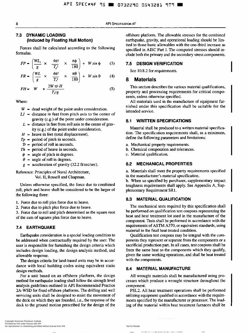
7.3 DYNAMIC LOADING (Induced by Floating Hull Motion)
Forces shall be calculated according to the following formulas.
F H - W + 2W I@ H
Where:
W = dead weight of the point under consideration. L1 = distance in feet from pitch axis to the center of
gravity (c.g.) of the point under consideration. L - distance in feet from roll axis to the center of grav-
ity (c.g.) of the point under consideration. H = heave in feet (total displacement). Tp = period of pitch in seconds. Tr = period of roll in seconds. Th = period of heave in seconds.
I#I - angle of pitch in degrees. 8 = angle of roll in degrees. g = acceleration of gravity (32.2 ft/sec/sec).
Reference: Principles of Naval Architecture, Vol. II, Rossel1 and Chapman.
Unless otherwise specified, the force due to combined roll, pitch and heave shall be considered to be the larger of the following three:
l . Force due to roll plus force due to heave. 2. Force due to pitch plus force due to heave. 3. Force due to roll and pitch determined as the square root of the sum of squares plus force due to heave.
7.4 EARTHQUAKE
Earthquake consideration is a special loading condition to be addressed when contractually required by the user. The user is responsible for furnishing the design criteria which includes design loading, the design analysis method, and allowable response.
The design criteria for land-based units may be in accor- dance with local building codes using equivalent static design methods.
For a unit based on an offshore platform, the design method for earthquake loading shall follow the strength level analysis guidelines outlined in API Recommended Practice 2A-WSD for fixed offshore platforms. The drilling and well servicing units shall be designed to resist the movement of the deck on which they are founded, i.e., the response of the deck to the ground motion prescribed for the design of the
offshore platform. The allowable stresses for the combined earthquake, gravity, and operational loading should be lim- ited to those basic allowables with the one-third increase as specified in AISC Part I. The computed stresses should in- clude both the primary and the secondary stress components.
7.5 DESIGN VERIFICATION See 10.8.2 for requirements. I
8 Materials This section describes the various material qualifications,
property and processing requirements for critical compo- nents, unless otherwise specified.
All materials used in the manufacture of equipment fur- nished under this specification shall be suitable for the intended service.
8.1 WRllTEN SPECIFICATIONS Material shall be produced to a written material specifica-
tion. The specification requirements shall, as a minimum, define the following parameters and limitations:
a. Mechanical property requirements. b. Chemical composition and tolerances. c. Material qualification.
8.2 MECHANICAL PROPERTIES a. Materials shall meet the property requirements specified in the manufacturer's material specification. b. When so specified by purchaser, supplementary impact toughness requirements shall apply. See Appendix A, S u p plementary Requirement SRI.
8.3 MATERIAL QUALIFICATION The mechanical tests required by this specification shall
be performed on qualification test coupons representing the heat and heat treatment lot used in the manufacture of the component. Tests shall be performed in accordance with the requirements of ASTM A370, or equivalent standards, using material in the final heat treated condition.
Qualification test coupons may be integral with the com- ponents they represent or separate from the components or a sacrificial production part. In all cases, test coupons shall be from the same heat as the components which they qualify, given the same working operations, and shall be heat treated with the components.
8.4 MATERIAL MANUFACTURE
All wrought materials shall be manufactured using pro- cesses which produce a wrought structure throughout the component.
PSL2. All heat treatment operations shall be performed utilizing equipment qualified in accordance with the require- ments specified by the manufacturer or processor. The load- ing of the material within heat treatment furnaces shall be
Copyright American Petroleum Institute Provided by IHS under license with API
Not for ResaleNo reproduction or networking permitted without license from IHS
SPECIFICATION FOR DRILLING AND WELL SERVICING STRUCTURES 9
such that the presence of any one part does not adversely af- fect the heat treatment lot. The temperature and time require- ments for heat treatment cycles shall be determined in accordance with the manufacturer’s or processor’s written specification. Actual heat treatment temperature and times shall be recorded and heat treatment records shall be trace- able to relevant components.
8.5 BOLTS
Bolts which conform to a recognized industry standard shall be marked in accordance with such standard, Other bolts may be used provided the chemical, mechanical and physical properties conform to the limits guaranteed by the bolt manufacturer.
8.6 WIRE ROPE
Wire rope for guy line or erection purposes shall conform to A P I Spec 9A: Specification for Wire Rope.
9 Welding Requirements 9.1 GENERAL
This section describes requirements for the welding of critical components.
9.2 WELDING QUALIFICATIONS
All welding undertaken on components shall be per- formed using welding procedures which are in accordance with AWS D1.l or similarly recognized industry standard.
This welding shall only be carried out by welders or weld- ing operators who are qualified in accordance with afore- mentioned standards. Workmanship and technique shall be in accordance with the same standard.
9.3 WRITTEN DOCUMENTATION
Welding shall be performed in accordance with welding procedure specifications ( W S ) written in accordance with applicable standard. The W S shall describe all the essential variables as listed in the applicable standard.
The use of prequalified joint details as specified in AWS DI.1 is acceptable. The manufacturer shall have a written W S for prequalified joints.
Weld joints and/or processes not meeting AWS D1.l requirements for prequalification shall be qualified per the applicable standard. The procedure qualification record (PQR) shall record all essential and supplementary essential (when required) variables of the weld procedure used for the qualification tests. Both the WPS and the PQR shall be maintained as records in accordance with the requirements of Section 11 of this specification.
9.4 CONTROL OF CONSUMABLES
Welding consumables shall conform to American Welding Society (AWS) or consumable manufacturers’ specifications.
The Manufacturer shall have a written procedure for stor- age and control of weld consumables. Materials of low hydrogen type shall be stored and used as recommended by the consumable manufacturer to retain their original low hydrogen properties.
9.5 WELD PROPERTIES
For all procedures requiring qualification, the mechanical properties of the weld, as determined by the procedure qual- ification test, shall at least meet the minimum specified mechanical properties required by the design. When impact testing is required for the base material, it shall also be a pro- cedure qualification requirement. Results of testing in the weld and base material heat affected zone (HAZ) shall meet the minimum requirements of the base material. In the case of attachment welds, only the HAZ of materials requiring impact testing shall meet the above requirements.
All weld testing shall be undertaken with the test weld- ment in the applicable post weld heat treated condition.
9.6 POST WELD HEAT TREATMENT
Post weld heat treatment of components shall be in accor- dance with the applicable qualified welding procedure spec- ification (WPS).
9.7 QUALITY CONTROL REQUIREMENTS
Requirements for quality control of permitted welds shall be in accordance with Section 10 of this specification. I
In addition to the requirements specified in 9.2 to 9.7, the following shall apply: I 9.8 SPECIFIC REQUIREMENT-REPAIR WELDS
9.8.1 Access
There shall be adequate access to evaluate, remove and in- spect the nonconforming condition which is the cause of the repair.
9.8.2 Fusion
The selected welding procedure specification ( W S ) and the available access for repair shall be such as to ensure com- plete fusion with the base material.
9.8.3 Heat Treatment
The welding procedure specification used for qualifying a repair shall reflect the actual sequence of weld repair and heat treatment imparted to the repaired item.
Copyright American Petroleum Institute Provided by IHS under license with API
Not for ResaleNo reproduction or networking permitted without license from IHS
This section specifies the quality control requirements for equipment and material. All quality control work shall be controlled by the manufacturer’s documented instructions which shall include appropriate methodology, quantitative and qualitative acceptance criteria.
The manufacturer shall have a program to ensure that the quality of products shall be planned, implemented and main- tained. The quality program shall be described in a quality manual, the issuance and revision of which shall be con- trolled and shall include a method to identify the latest revi- sions in the manual.
The acceptance status of all equipment, parts and materi- als shall be indicated either on the item or in the records related to the equipment, parts or materials.
10.2 QUALITY CONTROL PERSONNEL QUALIFICATIONS
10.2.1 NDE Personnel shall be qualified and/or certified in accordance with ASNT TC-IA, or an equivalent standard recognized by ASNT.
10.2.2 Personnel performing visual inspection of welding operations and completed welds shall be qualified and certi- fied as follows:
a. AWS certified welding inspector, or b. AWS certified associate welding inspector, or c. A welding inspector certified by the manufacturer’s doc- umented requirements which, as a minimum, includes a training program.
10.2.3 All personnel performing other quality control ac- tivities directly affecting material and product quality shall be qualified in accordance with the manufacturer’s docu- mented procedures.
10.3 MEASURING AND TEST EQUIPMENT
Equipment used to inspect, test or examine material or other equipment shall be identified, controlled, calibrated and adjusted at specific intervals in accordance with the manufacturer’s documented procedures, and consistent with a recognized industry standard to maintain the required level of accuracy.
10.4 NON-DESTRUCTIVE EXAMINATION
Instructions for non-destructive examination (NDE) activ- ities shall be detailed regarding the requirements of this spec- ification and those of all applicable referenced specifications. All NDE instructions shall be approved by an ASNT TC-IA level III examiner, or an examiner qualified to a standard rec- ognized by ASNT.
When examination is required it shall be done after final heat treatment.
The requirements of 10.4 shall apply to all critical compo- nents as designated by manufacturer’s design engineering department unless specified otherwise.
10.4.1 Visual Examination All critical welds shall be 100% visually examined.
10.4.2 Surface NDE ’henty percent (20%) of critical welds shall be inspected
using magnetic particle (MP) or liquid penetrant (LP) method in accordance with Section 6 of AWS D1.l. The manufacturer’s inspector shall choose areas for random in- spection coverage.
10.4.3 Volumetric NDE All full or partial penetration welds loaded in tension to
70% or greater of their allowable stress, as determined by design, shall be ultrasonic or radiograph inspected per Sec- tion 6 of AWS D 1 . l . The manufacturer’s design engineering department shall document the welds which require volu- metric NDE.
PSL2. Through Thickness NDE. Connections in critical components with through thickness tensile stresses greater than 70% of allowable stress, as determined by design, shall be ultrasonically inspected for laminations and internal dis- continuities in accordance with ASTM A578, with the fol- lowing changes.
10.4.3.1 Area of Examination The area to be examined shall include the weld area and
adjacent areas up to 3 inches from the weld. The area shall be 100% scanned.
10.4.3.2 Recording
referred to engineering for disposition:
a. All discontinuities causing a 50% loss of initial backwall regardless of size. b. All discontinuities with amplitudes greater than 50% of initial backwall which cannot be contained in a 1 inch circle. c. Any discontinuities which in the technician’s judgment would interfere with the ultrasonic inspection of the com- pleted weldment.
10.4.3.3 Disposition
pair requirements, if any.
10.4.3.4 Records
The following discontinuities shall be recorded and
Engineering shall review all recordings and determine re-
All recordings and dispositions shall be documented and records retained per Section 1 l .
Copyright American Petroleum Institute Provided by IHS under license with API
Not for ResaleNo reproduction or networking permitted without license from IHS
SPECIFICATION FOR DRILLING AND WELL SERVICING STRUCTURES 11
10.4.4 Acceptance Criteria
The acceptance criteria in Section 8 of AWS D l . 1 shall be used for visual, surface and volumetric NDE examination.
PSL2. Acceptance criteria for NDE examination for mast and derrick critical welds shall be per Section 9 of AWS I D1.l.
10.5 DIMENSIONAL VERIFICATION
Verification of dimensions shall be carried out on a sample basis as defined and documented by the manufacturer.
10.6 WORKMANSHIP AND FINISHING
10.6.1 Structural Steel
Structures and products produced shall conform to appli- cable sections of the AISC “Specification For Structural Steel Buildings”, concerning fabrication.
10.6.2 Castings
All castings shall be thoroughly cleaned, and all cored holes shall be drifted to ensure free passage of proper size bolt.
10.6.3 Protection
All forged, rolled structural steel shapes and plates, and castings shall be cleaned, primed and painted with a good grade of commercial paint or other specified coating before shipment. Machined surfaces shall be protected with a suit- able lubricate or compound.
10.6.4 Socketing
Socketing of raising, erection, or telescoping mast wire ropes shall be performed in accordance with practices out- lined by API Recommended Practice 9B. Socketed connec- I tions shall be proof tested per 10.8.3.
10.7 PURCHASER’S INSPECTION AND REJECTION
10.7.1 Inspection Notice
Where the inspector representing purchaser requests to inspect the product, the product at the works or witness test, the manufacturer shall give the inspector reasonable notice as to available inspection dates.
10.7.2 Inspection
While work on the purchaser’s product is being per- formed, the purchaser’s inspector shall have free entry at all times to all parts of the manufacturer works concerned with the manufacturer of the products ordered. The manufacturer shall afford the inspector, without charge, all reasonable
facilities to satisfy him that the product is being manufac- tured in accordance with this specification. All inspections should be made at the place of manufacturer prior to ship- ment, unless otherwise specified on the purchase order, and shall be so conducted as not to interfere unnecessarily with operation of the works, and refusal to do so shall be grounds for refusal of inspection.
10.7.3 Rejection
Material which shows injurious defects on inspection sub- sequent to acceptance at manufacturer’s works, or which proves defective when properly applied in service, may be rejected and the manufacturer so notified in writing. If tests that require the destruction of material are made, the pur- chaser shall pay for the material which meets the specifica- tion, but shall not pay for the material which fails to meet the specification.
10.7.4 Records
Full records of all calculations and tests shall be main- tained by the manufacturer. When requested by an actual prospective purchaser of the equipment for his use, or by a user of the equipment, the manufacturer shall make available for examination details of computations, drawings, test, or other supporting data as may be necessary to demonstrate compliance with this specification. It shall be understood that such information is for the sole use of the user or prospective purchaser for the purpose of checking the A P I rating, and that the manufacturer shall not be required to release the information from his custody.
10.8 TESTING
10.8.1 Proof Load Test
Proof load testing of products manufactured to this spec- ification is not a requirement of this specification. If proof load testing is desired, supplementary requirement SR2 (see Appendix A) may be specified in purchaser’s order. The magnitude of the load test shall be agreed upon by the pur- chaser and manufacturer.
10.8.2 Design Verification The accuracy of the standard design ratings of each struc-
ture shall be tested by proof loading or by a computer model such as FEA (Finite Element Analysis). The intent of such testing shall be to verify the structure for the Design Load- ings specified in Section 6.
Testing methods and assumptions shall be documented. Computer modeling documentation shall include loads, member .properties, model geometry and connectivity, mem- ber effective length factors and unbraced lengths, support conditions, member end fixities and analysis results demon- strating compliance with Section 7 of this specification. Doc-
Copyright American Petroleum Institute Provided by IHS under license with API
Not for ResaleNo reproduction or networking permitted without license from IHS
umentation shall be verified by a qualified individual other than the designer of the test.
10.8.3 Wire Rope Connections
Wire rope end connections used for erection purposes shall be proof tested to 50% of nominal wire rope assembly strength.
10.8.4 Cylinders and Winches
Cylinders and winches used for erection of masts or sub- structures shall be pressure tested to 1.5 times the system design working pressure. The test pressure shall be main- tained for a duration of ten minutes.
10.9 TRACEABILITY
Manufacturer shall obtain and retain a material test report on all steel material received having a specified yield strength greater than the following:
Any substitution of an alternate material to that called out in the engineering drawing or instructions should be docu- mented and traceable to the specific unit by serial number or similar specific identification.
PSL2. Critical components shall be traceable by heat and heat treatment lot identification. Identification shall be main- tained through all stages of manufacturing, traceable to the specific unit by a serial number.
PSL2. Certified reports shall constitute sufficient evidence of conformity for nonferrous materials and bearings.
PSL2. Bolts shall be exempt from the traceability require- ments, provided they are manufactured and marked in accor- dance with recognized industry standards.
11 Documentation 11.1 GENERAL
Full records of any documentation referenced in this spec- ification shall be kept by the manufacturer for a period of five years after the equipment has been manufactured and sold. Documentation shall be clear, legible, reproducible, re- trievable and protected from damage, deterioration, or loss.
All quality control records required by this specification shall be signed and dated. Computer sorted records shall contain originator’s personal code.
When requested by a purchaser of the equipment, author- ities or certifying agencies, the manufacturer shall make available all records and documentation for examination to demonstrate compliance with this specification.
11.2 DOCUMENTATION TO BE KEPT BY THE MANUFACTURER
The following documentation shall be kept by the manu- facturer:
a. Design documentation (See 7.5). b. Written specifications (See Sections 8,9, and 10). c. Qualification records such as:
l. Weld Procedure Qualification Records. 2. Welder Qualification Records. 3. NDE Personnel Qualification Records. 4. Measuring and Test Equipment Calibration Records.
d. Inspection and test records traceable to the equipment or components including:
1. Material test reports covering the following tests, as applicable: a. chemical analysis. b. tensile tests. c. impact tests. d. hardness tests. 2. NDE records covering the surface and/or volumetric NDE requirements of Section 10 of this specification. 3. Performance test records, where applicable, including: a. Proof load testing records. b. Hydrostatic pressure testing records. c. Slingline socket proof testing records. 4. Special Process Records, where applicable.
11.3 DOCUMENTATION TO BE DELIVERED WITH THE EQUIPMENT
11.3.1 Instructions
The manufacturer shall furnish to the purchaser one set of instructions that covers operational features, block reeving diagram, and lubrication points for each drilling or well ser- vicing structure. Instructions shall be included to cover erec- tion and lowering of the mast andor substructure. A facsimile of the nameplate shall be included in the instruc- tions.
11.3.2 Data Book
A comprehensive data book can be specified by the pur- chaser by calling out supplementary requirement SR3 (see Appendix A) in the purchase order.
Copyright American Petroleum Institute Provided by IHS under license with API
Not for ResaleNo reproduction or networking permitted without license from IHS
SR1 Low Temperature Testing This supplementary requirement shall apply when speci-
fied by purchaser. In all cases, the purchaser and manufac- turer shall agree upon the minimum design temperature and impact test result requirements.
Critical components shall be fabricated from materials possessing the specified notch toughness at the required min- imum design temperature. Impact testing shall be performed in accordance with the requirements of ASTM A370.
When it is necessary for sub-size impact test pieces to be used, the acceptance criteria shall be multiplied by the appro- priate adjustment factor listed in Table A-l. Sub-size test pieces of width less than 5 mm are not permitted.
Table A-1-Adjustment Factors for Sub-size Impact Specimens
Specimen Dimensions I I l l l lXl l lJn Adjustment Factor 10.0 x 7.5 0.833 10.0 x 5.0 0.667
Products meeting this supplementary requirement shall have their name plate stamped with SR1 and with the design minimum temperature in degrees C and the impact value in joules.
SR2 Proof Load Test The equipment shall be load tested to a load agreed upon
by the purchaser and manufacturer. After load testing, the
equipment shall be visually examined per 10.4.1 of this spec- ification.
The equipment shall have its name plate stamped with SR2 and the ratio of load test to design load (load testldesign load), example SR2-1 .O.
SR3 Data Book When requested by the purchaser, records shall be pre-
pared, gathered and properly collated in a data book by the manufacturer. The data book shall at least include for each unit:
a. Statement of compliance. b. Equipment designationkerial number. c. Assembly and critical area drawings. d. Nominal capacities and ratings. e. List of components. f. Traceability codes and systems (marking on parts/records on file). g. Steel grades. h. Heat treatment records. i. Material test reports. j. NDE records. k. Performance test records including functional hydrostatic and load testing certificates (when applicable). 1. Supplementary requirements certificates as required. m. Welding procedure specifications and qualification records. n. Instructions.
13
Copyright American Petroleum Institute Provided by IHS under license with API
Not for ResaleNo reproduction or networking permitted without license from IHS
B.l Derrick Structure B.2 Derrick Window A standard Derrick is a smcture of square cross section The demck window is shown in Fig. B-2. Window
that dimensionally agrees with a derrick size shown in Table arrangement Types A, C , D, and E shall be interchangeable. B-1, with dimensions as designated in Fig. B- l. The sizes and general dimensions of the V window opening
and drawworks are shown in Table B- l .
B.3 Foundation Bolt Settings Foundation bolt sizes and patterns are shown in Fig. B-3.
Bolt sizes are minimum and should be increased if stresses dictate larger diameter. Maximum reaction (uplift, compres- sion, and shear) as produced by the standard derrick loading of 6.1, and foundation bolt size and setting plan shall be fur- nished, on request, to the original user.
V - W I N D O W T Y P E A
DRbWWORKS WINDOW T Y P E C
the bottom of the crown block support beam.
top of the base plate.
the center line of the derrick side from top of base plate.
that would restrict passage of crown block.
poie and the top of the crown support beam.
A - The vertical distance from the top of the base plate to
B - The distance between heel t o heel of adiacent legs at the
C - The window opening measured in the clear and parallel to
D - The smallest clear dimension at the top of the derrick
E - The clearance between the horizontal header of the gin DRAWWORKS WINDCN T Y P E D
LADDER W l N W W T Y P E E
11.-)21
Figure El-Derrick Dimensions Figure B-2-Derrick Windows
C.1 Marking The following marking requirements apply to licensed
manufacturers using the API monogram on products covered by this specification.
C.l .I NAMEPLATE
Drilling and well servicing structures manufactured in accordance with these specifications shall be identified by a nameplate bearing at least the information specified in the following paragraphs. Markings shall be either raised or stamped. The API monogram shall be at least ‘/2” high. The nameplate shall be securely affixed to the structure in a con- spicuous place.
C.1.2 MAST AND DERRICK NAMEPLATE INFORMATION
a. Manufacturer’s name. b. Manufacturer’s address.
d. API monogram. e. Serial number, f. Height in feet. g. Maximum rated static hook load, in pounds, with guy lines if applicable for stated number of lines to traveling block. h. Maximum rated wind velocity in knots, with guy line if applicable, with rated capacity of pipe racked. i. The API specification and edition of the API specification under which the structure was designed and manufactured. j. Manufacturer’s guying diagram-for structures as appli- cable k. Following note shall appear on the nameplate:
CAUTION: ACCELERATION OR IMPACT, ALSO SET- BACK AND WIND LOADS WILL REDUCE THE MAX- IMUM RATED STATIC HOOK LOAD CAPACITY.
1. Manufacturer’s load distribution diagram. (May be placed
I c. Date of manufacture, including month and year.
in mast instructions.) m. Graph plotting maximum allowable static hook load ver- sus wind velocity as defined in 5.1.6 and 5.3.5. n. Mast setup distance for mast with guy lines. o. PSL 2, if applicable. p. Supplementary requirement information as specified by the particular SR, if applicable. q. Manufacturer’s license number.
C.1.3 SUBSTRUCTURE NAMEPLATE INFORMATION
a. Manufacturer’s name. b. Manufacturer’s address. c. Date of manufacture, including month and year. d. API monogram. e. Serial number. f. Maximum rated static rotary capacity. g. Maximum rated pipe setback capacity. h. Maximum combined rated static rotary and rated setback capacity. i. API specification and edition of the API specification under which the structure was designed and manufactured. j. PSL2, if applicable. k. Supplementary requirement information as specified by the particular SR, if applicable. 1. Manufacturer’s license number. I C.1.4 CROWN BLOCK INFORMATION
a. Manufacturer’s name. b. Manufacturer’s address. c. Date of manufacture, including month and year. d. Serial number. e. Maximum rated static hook load. f. API specification and edition of the API specification under which the structure was designed and manufactured. g. PSL 2, if applicable. h. API monogram. i. Manufacturer’s license number.
I
17
Copyright American Petroleum Institute Provided by IHS under license with API
Not for ResaleNo reproduction or networking permitted without license from IHS