8
Peripheral-Feed Center Take-Off Clarifier for the Highest Quality Effluent 2 to 4 Times More Hydraulically Efficient than Center-Feed Clarifiers Spiraflo Clarifier
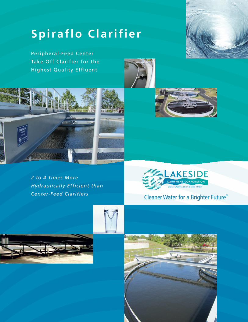
Peripheral-Feed Center
Take-Off Clarif ier for the
Highest Quality Effluent
2 to 4 Times More
Hydraulically Efficient than
Center-Feed Clarifiers
Sp i raf lo C la r i f ie r
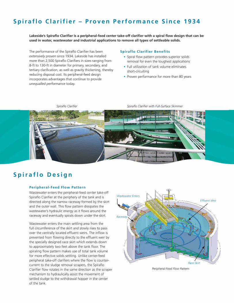
Wastewater Enters
S p i r a f l o C l a r i f i e r – P ro v e n P e r f o r m a n c e S i n c e 1 9 3 4
Lakeside’s Spiraflo Clarifier is a peripheral-feed center take-off clarifier with a spiral flow design that can be used in water, wastewater and industrial applications to remove all types of settleable solids.
Spiraflo Clarif ier Benefits
• Spiral flow pattern provides superior solids removal for even the toughest applications
• Full utilization of tank volume eliminates short-circuiting
• Proven performance for more than 80 years
Spiraflo Clarifier Spiraflo Clarifier with Full-Surface Skimmer
S p i r a f l o D e s i g n
Effluent Weir
Race Skirt
Peripheral-Feed Flow Pattern
Raceway
Peripheral-Feed Flow Pattern
Wastewater enters the peripheral-feed center take-off Spiraflo Clarifier at the periphery of the tank and is directed along the narrow raceway formed by the skirt and the outer wall. This flow pattern dissipates the wastewater’s hydraulic energy as it flows around the raceway and eventually spirals down under the skirt.
Wastewater enters the main settling area from the full circumference of the skirt and slowly rises to pass over the centrally located effluent weirs. The inflow is prevented from flowing directly to the effluent weir by the specially designed race skirt which extends down to approximately two feet above the tank floor. The spiraling flow pattern makes use of total tank volume for more effective solids settling. Unlike center-feed peripheral take-off clarifiers where the flow is counter-current to the sludge removal scrapers, the Spiraflo Clarifier flow rotates in the same direction as the scraper mechanism to hydraulically assist the movement of settled sludge to the withdrawal hopper in the center of the tank.
The performance of the Spiraflo Clarifier has been extensively proven since 1934. Lakeside has installed more than 2,500 Spiraflo Clarifiers in sizes ranging from 8-ft to 130-ft in diameter for primary, secondary, and tertiary clarification, as well as gravity thickening, thereby reducing disposal cost. Its peripheral-feed design incorporates advantages that continue to provide unequalled performance today.
S p i r a f l o H y d r a u l i c A d v a n t a g e s
The Spiraflo’s peripheral-feed design provides the best hydraulic flow pattern and minimizes many of the problems associated with center-feed peripheral take-off clarifier hydraulics.
Eliminates the Waterfal l Effect
The influent well in a center-feed clarifier deflects the high velocity inflow downward, creating a waterfall effect. This velocity combined with the higher density of settling solids disturbs the sludge blanket at the bottom of the tank and interferes with proper solids removal.
Because the Spiraflo’s incoming flow enters around the entire periphery of the skirt (baffle), the flow spirals in the raceway dissipating the energy before it enters the main settling area. Any velocity remaining in the flow as it moves below the skirt is directed toward the center of the tank in a spiral pattern over the entire circumference of the skirt.
Eliminates Sludge Wall Creep
In a center-feed clarifier, the velocity created by the waterfall effect moves solids from the center of the tank to the outer wall. This movement, known as sludge wall creep, can push solids up the outer wall and over the effluent weir and can greatly reduce effluent quality. Expensive energy dissipation feedwells, mid-radius baffles, and Crosby (Stamford) baffles are often added to mitigate sludge wall creep and the loss of solids.
In the Spiraflo Clarifier, the flow travels inward from the skirt towards the center of the tank. This movement coincides with the direction of the scraper mechanism and assists in moving sludge to the central hopper.
Eliminates Short-Circuiting
The center-feed peripheral take-off clarifier flow pattern, created by the waterfall effect and sludge wall creep, causes influent to flow directly to the effluent weir. This short-circuiting prevents complete use of the tank volume for the settling process.
The Spiraflo’s spiraling flow pattern flows around the entire periphery and under the skirt eliminating all possibility of short-circuiting and ensuring maximum use of the entire tank volume.
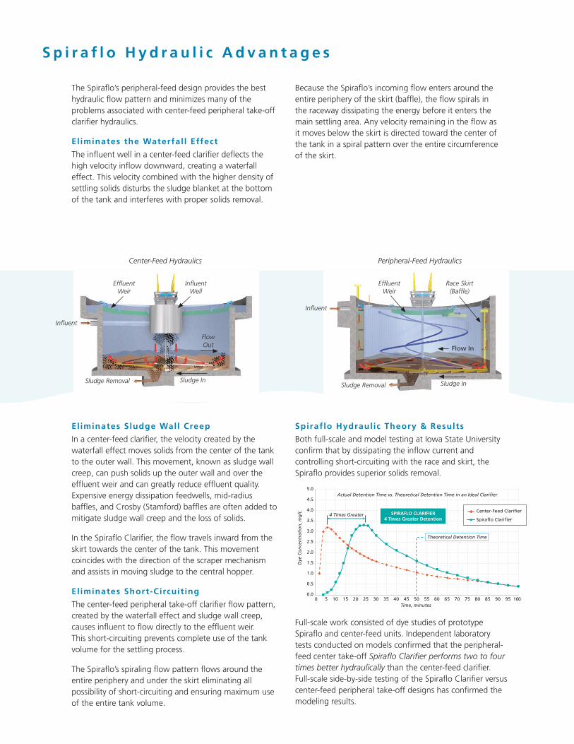
Center-Feed Hydraulics Peripheral-Feed Hydraulics
Spiraflo Hydraulic Theory & Results
Both full-scale and model testing at Iowa State University confirm that by dissipating the inflow current and controlling short-circuiting with the race and skirt, the Spiraflo provides superior solids removal.
Full-scale work consisted of dye studies of prototype Spiraflo and center-feed units. Independent laboratory tests conducted on models confirmed that the peripheral- feed center take-off Spiraflo Clarifier performs two to four times better hydraulically than the center-feed clarifier. Full-scale side-by-side testing of the Spiraflo Clarifier versus center-feed peripheral take-off designs has confirmed the modeling results.
0.0
0.5
1.0
1.5
2.0
2.5
3.0
3.5
4.0
4.5
5.0
0 5 10 15 20 25 30 35 40 45 50 55 60 65 70 75 80 85 90 95 100
Dye
Co
nce
ntr
atio
n, m
g/L
Time, minutes
SPIRAFLO CLARIFIER4 Times Greater Detention
4 Times Greater
Actual Detention Time vs. Theoretical Detention Time in an Ideal Clarifier
Theoretical Detention Time
Center-Feed Clarifier
Spiraflo Clarifier
Effluent Weir
Influent
Sludge Removal Sludge In
Flow Out
Influent Well
Effluent Weir
Influent
Sludge Removal Sludge In
Flow In
Race Skirt (Baffle)
S l u d g e R e m o v a l
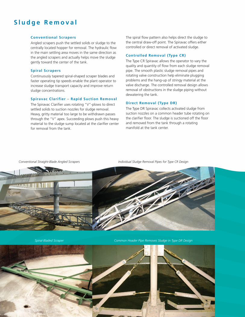
Conventional Scrapers
Angled scrapers push the settled solids or sludge to the centrally located hopper for removal. The hydraulic flow in the main settling area moves in the same direction as the angled scrapers and actually helps move the sludge gently toward the center of the tank.
Spiral Scrapers
Continuously tapered spiral-shaped scraper blades and faster operating tip speeds enable the plant operator to increase sludge transport capacity and improve return sludge concentrations.
Spiravac Clarif ier – Rapid Suction Removal
The Spiravac Clarifier uses rotating “V”-plows to direct settled solids to suction nozzles for sludge removal. Heavy, gritty material too large to be withdrawn passes through the “V” apex. Succeeding plows push this heavy material to the sludge sump located at the clarifier center for removal from the tank.
The spiral flow pattern also helps direct the sludge to the central draw-off point. The Spiravac offers either controlled or direct removal of activated sludge.
Controlled Removal (Type CR)
The Type CR Spiravac allows the operator to vary the quality and quantity of flow from each sludge removal pipe. The smooth plastic sludge removal pipes and rotating valve construction help eliminate plugging problems and the hang-up of stringy material at the valve discharge. The controlled removal design allows removal of obstructions in the sludge piping without dewatering the tank.
Direct Removal (Type DR)
The Type DR Spiravac collects activated sludge from suction nozzles on a common header tube rotating on the clarifier floor. The sludge is suctioned off the floor and removed from the tank through a rotating manifold at the tank center.
Conventional Straight-Blade Angled Scrapers Individual Sludge Removal Pipes for Type CR Design
Common Header Pipe Removes Sludge in Type DR DesignSpiral-Bladed Scraper
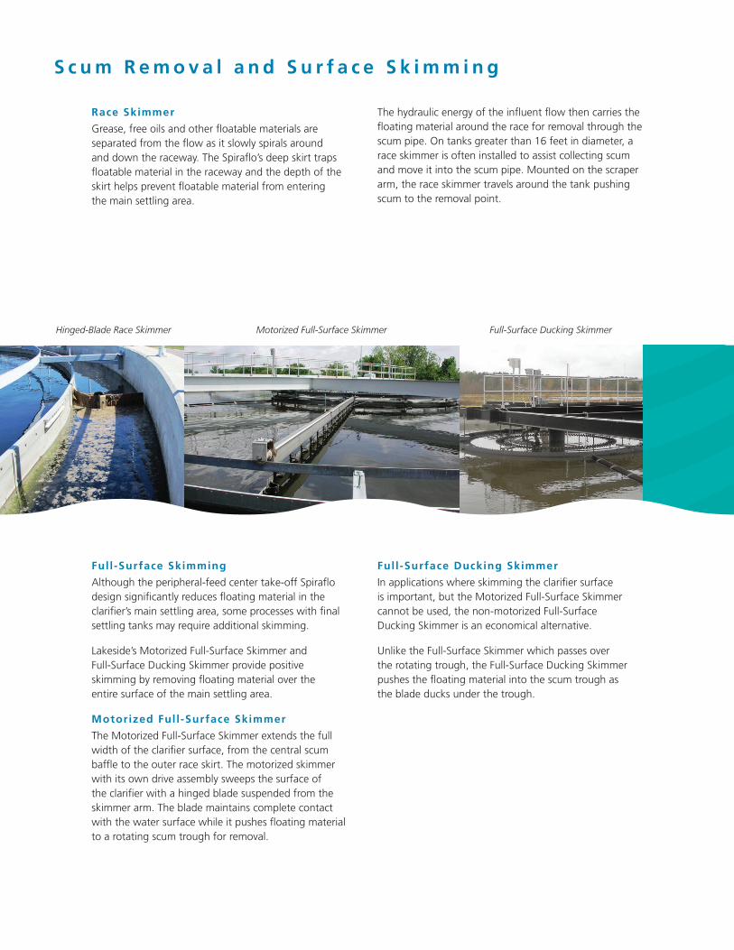
Race Skimmer
Grease, free oils and other floatable materials are separated from the flow as it slowly spirals around and down the raceway. The Spiraflo’s deep skirt traps floatable material in the raceway and the depth of the skirt helps prevent floatable material from entering the main settling area.
The hydraulic energy of the influent flow then carries the floating material around the race for removal through the scum pipe. On tanks greater than 16 feet in diameter, a race skimmer is often installed to assist collecting scum and move it into the scum pipe. Mounted on the scraper arm, the race skimmer travels around the tank pushing scum to the removal point.
Full-Surface Skimming
Although the peripheral-feed center take-off Spiraflo design significantly reduces floating material in the clarifier’s main settling area, some processes with final settling tanks may require additional skimming.
Lakeside’s Motorized Full-Surface Skimmer and Full-Surface Ducking Skimmer provide positive skimming by removing floating material over the entire surface of the main settling area.
Motorized Full-Surface Skimmer
The Motorized Full-Surface Skimmer extends the full width of the clarifier surface, from the central scum baffle to the outer race skirt. The motorized skimmer with its own drive assembly sweeps the surface of the clarifier with a hinged blade suspended from the skimmer arm. The blade maintains complete contact with the water surface while it pushes floating material to a rotating scum trough for removal.
Hinged-Blade Race Skimmer Motorized Full-Surface Skimmer
S c u m R e m o v a l a n d S u r f a c e S k i m m i n g
Full-Surface Ducking Skimmer
In applications where skimming the clarifier surface is important, but the Motorized Full-Surface Skimmer cannot be used, the non-motorized Full-Surface Ducking Skimmer is an economical alternative.
Unlike the Full-Surface Skimmer which passes over the rotating trough, the Full-Surface Ducking Skimmer pushes the floating material into the scum trough as the blade ducks under the trough.
Full-Surface Ducking Skimmer
P r i m a r y C l a r i f i c a t i o n
Primary clarifiers are utilized to provide a principle degree of wastewater treatment prior to the biological treatment process. Efficiently designed and operated primary clarifiers will remove from 50 to 70 percent of the influent total suspended solids (TSS) and from 25 to 40 percent of influent biochemical oxygen demand (BOD5).
Improved Removal Efficiency
Full-scale side-by-side testing of Spiraflo Clarifiers and center-feed clarifiers has demonstrated that the peripheral-feed center take-off Spiraflo can remove 20 percent more TSS and BOD5 thus reducing the loadings on the biological treatment process and improving overall performance.
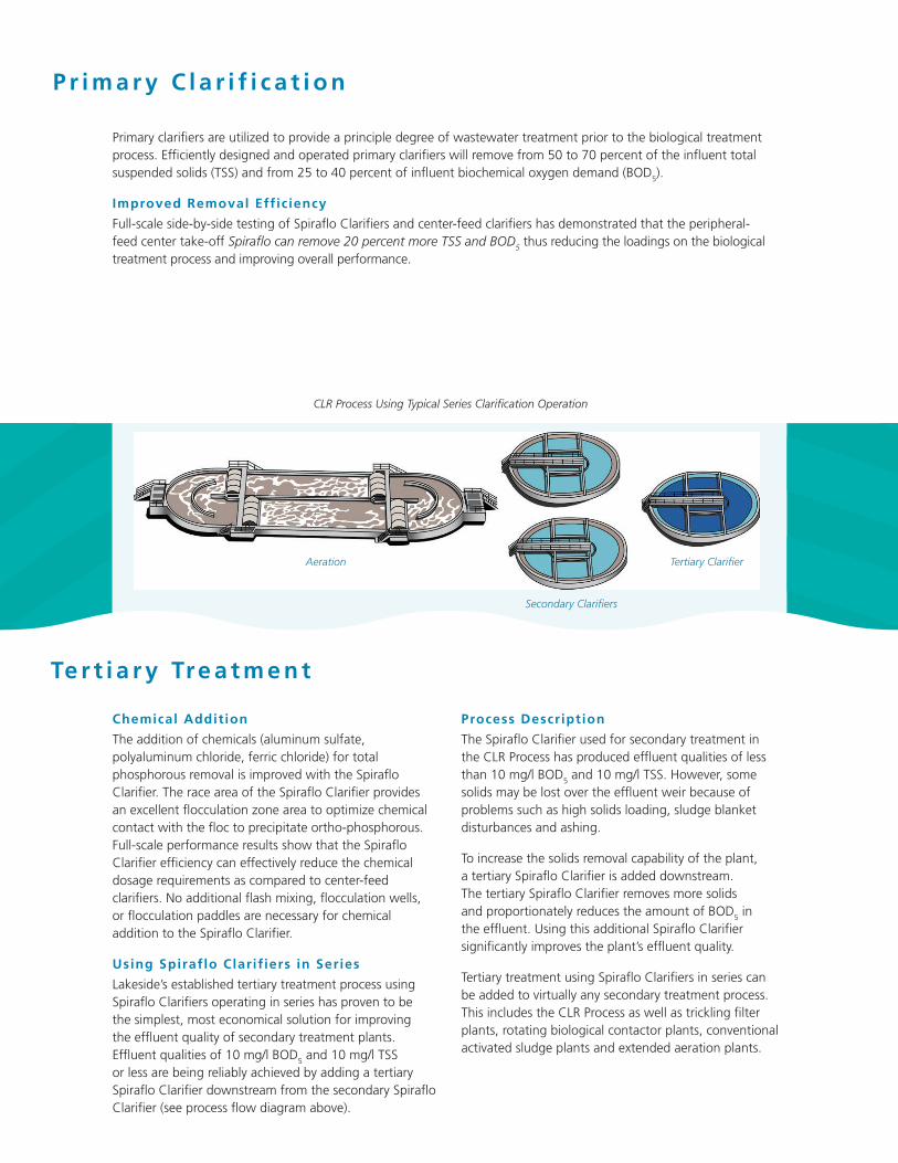
CLR Process Using Typical Series Clarification Operation
Te r t i a r y Tre a t m e n t
Chemical Addition
The addition of chemicals (aluminum sulfate, polyaluminum chloride, ferric chloride) for total phosphorous removal is improved with the Spiraflo Clarifier. The race area of the Spiraflo Clarifier provides an excellent flocculation zone area to optimize chemical contact with the floc to precipitate ortho-phosphorous. Full-scale performance results show that the Spiraflo Clarifier efficiency can effectively reduce the chemical dosage requirements as compared to center-feed clarifiers. No additional flash mixing, flocculation wells, or flocculation paddles are necessary for chemical addition to the Spiraflo Clarifier.
Using Spiraflo Clarif iers in Series
Lakeside’s established tertiary treatment process using Spiraflo Clarifiers operating in series has proven to be the simplest, most economical solution for improving the effluent quality of secondary treatment plants. Effluent qualities of 10 mg/l BOD5 and 10 mg/l TSS or less are being reliably achieved by adding a tertiary Spiraflo Clarifier downstream from the secondary Spiraflo Clarifier (see process flow diagram above).
Process Description
The Spiraflo Clarifier used for secondary treatment in the CLR Process has produced effluent qualities of less than 10 mg/l BOD5 and 10 mg/l TSS. However, some solids may be lost over the effluent weir because of problems such as high solids loading, sludge blanket disturbances and ashing.
To increase the solids removal capability of the plant, a tertiary Spiraflo Clarifier is added downstream. The tertiary Spiraflo Clarifier removes more solids and proportionately reduces the amount of BOD5 in the effluent. Using this additional Spiraflo Clarifier significantly improves the plant’s effluent quality.
Tertiary treatment using Spiraflo Clarifiers in series can be added to virtually any secondary treatment process. This includes the CLR Process as well as trickling filter plants, rotating biological contactor plants, conventional activated sludge plants and extended aeration plants.
Aeration
Secondary Clarifiers
Tertiary Clarifier
S p i r a f l o v s . C e n t e r- F e e d C o s t C o m p a r i s o n
Tank Excavation
Both center-feed and Spiraflo tanks require excavation, but excavation is more expensive and time consuming for a center-feed clarifier. Influent pipes for larger center-feed clarifiers are installed under the tank floor requiring deeper excavation for gravel bedding or concrete encasement.
Excavation costs for a Spiraflo tank are less because the tank is constructed without the below-grade influent pipe and peripheral effluent trough used for center-feed clarifiers.
Tank Construction
The center-feed’s concrete peripheral effluent trough is a costly addition to tank construction. The cantilevered trough requires extra reinforcing steel to withstand design loads, special formwork to construct and extra concrete pours to complete the tank wall.
Spiraflo effluent troughs are part of the clarifier equipment provided by Lakeside. The effluent troughs are installed inside the tank and are not part of the poured concrete walls. Tank walls are straight and therefore make forming less expensive, steel reinforcing simpler, and concrete pouring easier. Less concrete is required and the simple forms save time and money needed for tank construction.
Common Flow Splitter and Effluent Scum Box
To ensure even flow and solids splitting to each clarifier, a common splitter box is provided. This splitter box can also be designed with a common effluent box and a common scum box to save construction costs as compared to center-feed clarifiers that require expensive buried piping and valves.
Additional Equipment
Expensive Crosby (Stamford baffles), energy dissipation feedwells, flocculation wells, and mid-radius baffles are often used in an attempt to diminish the center-feed clarifier’s short-circuiting and waterfall effect.
No such additional equipment is required for the peripheral-feed center take-off Spiraflo Clarifier design.
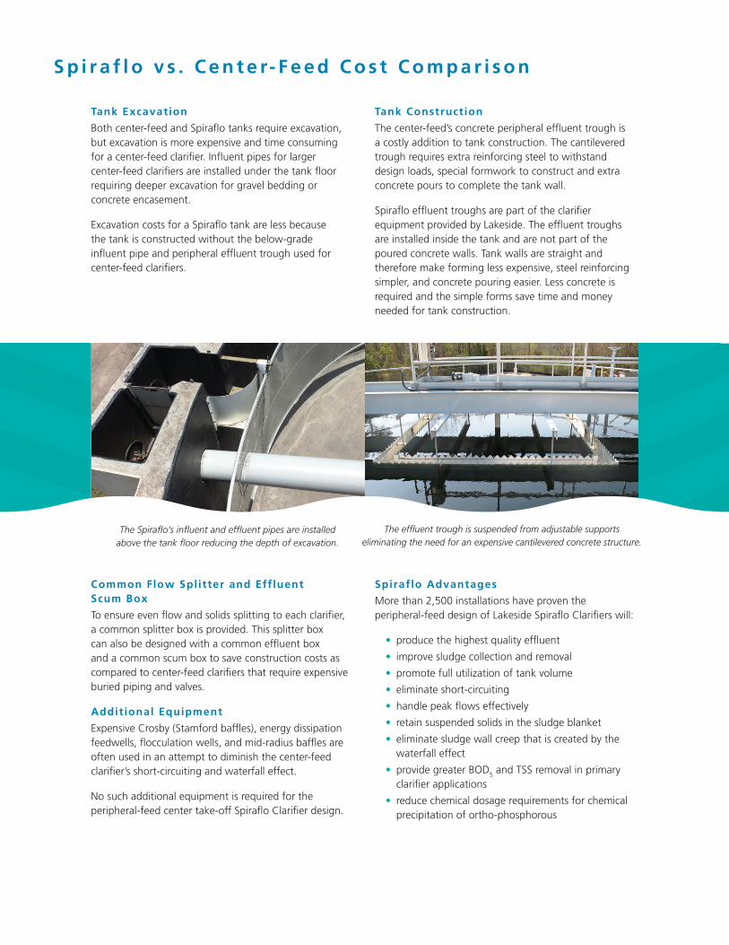
The Spiraflo’s influent and effluent pipes are installed above the tank floor reducing the depth of excavation.
The effluent trough is suspended from adjustable supports eliminating the need for an expensive cantilevered concrete structure.
Spiraflo Advantages
More than 2,500 installations have proven the peripheral-feed design of Lakeside Spiraflo Clarifiers will:
• produce the highest quality effluent
• improve sludge collection and removal
• promote full utilization of tank volume
• eliminate short-circuiting
• handle peak flows effectively
• retain suspended solids in the sludge blanket
• eliminate sludge wall creep that is created by the waterfall effect
• provide greater BOD5 and TSS removal in primary clarifier applications
• reduce chemical dosage requirements for chemical precipitation of ortho-phosphorous
Treatment Equipment and Process Solutions from
Lakeside Equipment Corporation
Lakeside offers a wide range of equipment and systems for virtually all stages of wastewater treatment from influent through final discharge. Each process and equipment item that we supply is manufactured with one goal: to reliably improve the quality of our water resources in the most cost-effective way. We have been doing just that since 1928.
Screen and Trash Rakes Hydronic T Series Hydronic K Series Hydronic Multifunctional Series Hydronic H Series Catronic Series Monorail Series HY-TEC Screen CO-TEC Screen RO-TEC Screen
Grit Collection SpiraGrit Vortex Grit Removal System Aeroductor Grit Removal System In-Line Grit Collector Raptor® Grit Washer Grit Classifier H-PAC®
Clarif ication and Fi ltration Spiraflo Clarifier Spiravac Clarifier Full Surface Skimming MicroStar® Filter
Screw Pumps Open Screw Pumps Enclosed Screw Pumps
Raptor® Screening Fine Screen Micro Strainer Rotating Drum Screen Septage Acceptance Plant Septage Complete Plant Complete Plant Multi-Rake Bar Screen TalonRake Bar Screen Rotary Strainer Screen Wash Press
Biological Treatment CLR Process Magna Rotor Aerators & Accessories Sequencing Batch Reactors Package Treatment Plants Submersible Mixers & Recirculation Pumps
Hauled Waste Receiving Systems Raptor® Septage Acceptance Plant Raptor® Septage Complete Plant
Package Headworks Systems Raptor® Complete Plant H-PAC®
Biological Treatment Systems CLR Process Package Treatment Plants Sequencing Batch Reactors
All trademarks owned by Lakeside Equipment Corporation. ©2018 Lakeside Equipment Corporation 10/18 www.lakeside-equipment.com
1022 E. Devon, P.O. Box 8448Bartlett, IL 60103630.837.5640 FAX: 630.837.5647E-mail: [email protected]


