Spray Theory and Applications Prof. Mahesh V. Panchanula Department of Mechanical Engineering Indian Institute of Technology, Madras Lecture - 10 Introduction to Atomizers and their design-2 Good Morning. We are going to continue our discussion on various spray nozzle designs. Towards the end of the class, we had looked at the 2 sorts of designs of spray nozzles; one that is just a through hole through which you squared a liquid that is pressurized a design that is commonly used in diesel injectors. (Refer Slide Time: 00:44) And another which is more widely used design called the simplex swirl atomizer. This simplex swirl atomizer is very simple in its construction, essentially a set of tangential passages bring the fluid into a chamber called the swirl chamber and that swirl chamber has a converging passage in which the swirl action is accelerated. The swirl velocity is accelerated and the acceleration causes the liquid to exit the spray nozzle by just forming into a thin film that is sticking to the walls of the orifice. And the big advantage of this design as we discussed in that class, is that the size of the film that is formed is what is going to determine the drop size later on not the size of the orifice. I have now sought of decoupled machining practices from fluid mechanic performance of the spray nozzle which is always a good thing.
Transcript
Spray Theory and Applications
Prof. Mahesh V. Panchanula
Department of Mechanical Engineering
Indian Institute of Technology, Madras
Lecture - 10
Introduction to Atomizers and their design-2
Good Morning. We are going to continue our discussion on various spray nozzle designs.
Towards the end of the class, we had looked at the 2 sorts of designs of spray nozzles;
one that is just a through hole through which you squared a liquid that is pressurized a
design that is commonly used in diesel injectors.
(Refer Slide Time: 00:44)
And another which is more widely used design called the simplex swirl atomizer. This
simplex swirl atomizer is very simple in its construction, essentially a set of tangential
passages bring the fluid into a chamber called the swirl chamber and that swirl chamber
has a converging passage in which the swirl action is accelerated. The swirl velocity is
accelerated and the acceleration causes the liquid to exit the spray nozzle by just forming
into a thin film that is sticking to the walls of the orifice. And the big advantage of this
design as we discussed in that class, is that the size of the film that is formed is what is
going to determine the drop size later on not the size of the orifice.
I have now sought of decoupled machining practices from fluid mechanic performance
of the spray nozzle which is always a good thing.
(Refer Slide Time: 01:50)
What we are going to do, just briefly is to look at one of these spray nozzles in action.
We are going to look at a video of a fairly common spray simplex swirl nozzle from a
water spray container. We will see in just a moment. Let me start to play the video. This
was captured at 10000 frames seconds and is being played back at 30 frames a second.
(Refer Slide Time: 02:17)
Let me pause the video here. Now, what you see over here is the tip of the spray
container. What you see coming out is a conical sheet of water and a conical sheet of
water, when I play this you will see is not just a steady cone, it is sort of flapping; it is
got a temporal oscillation to it, it is flapping and is undergoing let me pause the video, is
undergoing as certain kind of breakup process.
So this flapping liquid sheet exiting the swirl spray nozzle is what is responsible for its
breakup. And as you can see the sheet is breaking up right around the region where my
mouse is pointing. And for the downstream you essentially have drops that are moving
down stream. This is an instance where you know the sheet thickness is not very obvious
in this film, but the sheet thickness is much smaller than the orifice through which the
sheet is exiting. And that sheet because of its unsteadiness is response for the sheet itself
breaking up into what looks like rings, you can see the oscillatory motion of the sheet.
Now, we will go back to make some observations. Now if you look at this, there is the
conical sheet exit in the nozzle is not steady and it is flapping and this flapping motion is
due to the swirl action which is causing the liquid sheet expand out words and the very
fact that fluid mechanically. This kind of a velocity profile is unstable. We will look at
that as we go long as well. Now this flapping liquid sheet causes the liquid sheet, in this
particular instance you can see evidence that it is sort of breaking up into rings and the
rings themselves are further breaking up into drops for the downstream.
If you will imagine for a moment, a sheet like this breaking up into rings, the ring
diameter or if you will, it is like a toroidal ring, the torus diameter is now going to be
determined by the film thickness. It is going to be on the order of the film thickness. And
that film thickness being small by accelerated swirl is naturally going to be responsible
for smaller drop down stream. That is the mechanism by which drop size is controlled in
a design like this. Another feature to observe here is that well again it is not very obvious
here, but the fact that I have spread the liquid out into a swirling liquid sheet is going to
naturally cause all the drops to be concentrated in a donut of sort weather hole in the
middle where there is no concentration of fluid.
Now, there may be applications where that is good where I want all of the drops to be
only on the periphery I do not want anything in the middle, but in instance is where I
want a uniform distribution of drops. For example a paint spray, when I paint a wall, I
want to have a relatively uniform coating all over. I do not want a thick edge on top and
bottom of the spray and a sort of less than coating in the middle, I do not want that.
I would rather prefer a full a sort of a more uniform coating of the spray paint. And for
that, there are designs that have evolved which are sort of evolutions from the simplex
nozzle. The simplex atomizer is like a swirl. It is one of the most widely used and many
of the other designs, we will see today are all based on the basics simplex concept. One
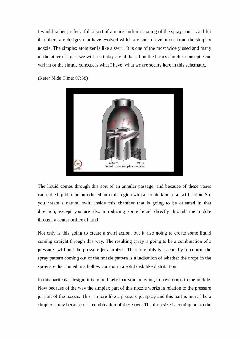
variant of the simple concept is what I have, what we are seeing here in this schematic.
(Refer Slide Time: 07:38)
The liquid comes through this sort of an annular passage, and because of these vanes
cause the liquid to be introduced into this region with a certain kind of a swirl action. So,
you create a natural swirl inside this chamber that is going to be oriented in that
direction; except you are also introducing some liquid directly through the middle
through a center orifice of kind.
Not only is this going to create a swirl action, but it also going to create some liquid
coming straight through this way. The resulting spray is going to be a combination of a
pressure swirl and the pressure jet atomizer. Therefore, this is essentially to control the
spray pattern coming out of the nozzle pattern is a indication of whether the drops in the
spray are distributed in a hollow cone or in a solid disk like distribution.
In this particular design, it is more likely that you are going to have drops in the middle.
Now because of the way the simplex part of this nozzle works in relation to the pressure
jet part of the nozzle. This is more like a pressure jet spray and this part is more like a
simplex spray because of a combination of these two. The drop size is coming out to the
pressure jet are going to be generally larger than the drop sizes in the simplex spray.
While I have ensured that there is sort of a more uniform volume drop volume
distribution that drop volume in the middle of this spray near the center line of this spray
is going to be distributed in to larger drops in comparison with the drops on the periphery
of this spray. So, this is sort of a by result of this kind of a design, there is really no way
around it as far as this design is concerned. But we at least overcome the problem of
having nothing in the middle, no fuel or no liquid in the middle.
(Refer Slide Time: 10:27)
The next kind of design is again offshoot of this simplex nozzle and this particular design
is, it simplifies a few different aspects of this simplex nozzle by making the passages
fairly large. This is again a schematic, where the liquid is injected through the middle
through this, what we are seeing here is sort of a cut section of the nozzle itself. And
there is an insert this is typically called as swirl insert.
That is responsible; it is sort of like 2 fans, 2 vanes in that are oriented as an x. The liquid
that comes up, the first vane is going to cause a swirling action in this direction. The
liquid that comes up this vane is going to cause a swirling action this way. And by
engineering a small passage here, we can cause some fluid to come directly down the
middle as well.
That column of fluid that comes down the middle is also going to be in the vicinity of
this swirl vortex that is formed inside the simplex nozzle. As a result it is also going to be
a swirl in column of liquid that is going to come out in the form of a spray. Again you
are, this is solid cone design, but by taking this y, I am going to try and draw a schematic
of this, the fluid that comes of this way is going to cause it swirl, this way the fluid that
comes up the other way is going to cause it swirl. This way and that causes swirling
action in this swirl chamber.
The drop size in this case is again determined by the angle of this swirl, insert in some
sense that angle is going to determine the magnitude of the swirl velocity in relation to
the axial velocity and that essentially determines like the swirl momentum flux like swirl
momentum flux is, what is responsible for the degree to which the film is sticking to the
wall.
(Refer Slide Time: 13:32)
One of the features of all of these nozzles is that I have one fluid inlet that brings fluid
into the nozzle and all the fluid that enters the nozzle is spread now as I increase the
supply pressure.
If you go back to the simplex design for a moment as we increase the supply pressure at
this point which is a same at all the 4 inlets, as we increase that supply pressure, you
likely to see that the flow rate through this nozzle goes up. Because the geometry of the
passages remains the same as the pressure goes up the flow rate through the nozzle goes
up, as the flow rate goes up because of the nature of the geometry the swirl velocity also
goes up. There is a range of operation where increase in the pressure increases the flow
rate without adversely affecting the drop size in the spray that is usually the range where
simplex nozzles are employed.
But, because of the nature of this feature; essentially if you will imagine, these are like
restrictions they are like fluid mechanic restrictions, people are found over many, many
kinds of designs that in a typical simplex spray Q goes as this square root of delta p. I use
the symbol delta p for supply pressure. It is essentially that difference in the pressure
between the actual absolute pressure at which the liquid is supplied and the pressure into
which the spray enters. Assume for a moment that the spray enters pure ambient
condition. So delta p is the same as the gauge pressure that at the entry to the nozzle.
And this relation that the flow rate goes as square root of delta p is sort of empirically
observed in many, many different kinds of nozzles, actual data shows that this is the
exponent is not exactly 0.5, but close to 0.45. Q goes as delta p raise to the power 0.45
that is again over a wide class of simplex nozzle. There is a problem with this square root
kind of dependence that if I increase the supply pressure by a factor of 4, I only get a
factor of two changes in the flow rate.
If I want to double the flow rate conversely, I have to increase the supply pressure 4
times which is usually quite difficult to do. Just too again gets some order of magnitude,
estimates most simplex spray nozzles operated pressures between about 2 bar 2 about 7
bar. Like for example, your spray water can that we saw just a moment ago is probably
the nozzle part itself is operating at a pressure about 2 to 3 bar. To go up from about 2
bar if i have to double the flow rate coming out, I have to go up to 8 bar which is
prohibitive in many application.
But, on the other hand I want to be able to modulate the fuel output coming out in the
form of a spray. I want to be able to control what comes out, the mass flow rate of the let
us just say fuel that comes out of this spray nozzle, because for one simple example, is
let us take a process furnace. I have a boiler in which, there is an oil fired burner. We are
spraying some kind of petroleum based oil into it into a combustion chamber to create
heat for use in a process heating application. Now when I start off this process cold on a
Monday morning, I require a high through put of this of heat and consequently a high oil
flow rate. But, after I have heated off the contents of this, let us just say boiler or the
process heater up to a certain temperature, I will only want to maintain it that
temperature I do not, I only want to add as much heat as required to overcome losses
around the losses to the ambient environment.
The startup requires a very high flow rate the maintenance of that temperature only
requires, what is often called trickle heating. So, what sort of a spray nozzle can I use
that will give me certain flow rate for startup conditions and something like a 10th of the
flow rate during normal operating conditions. This kind of a problem is also encountered
in an aircraft, where at the take of point the pilot is running an aircraft a full thrust which
is when all the atomizers are firing at their highest flow rate. But, when the pilot is only
cruising at some high altitude, you do not require full thrust. And so the spray nozzles
have to now scale back and operate that a much at a much lower flow rate condition.
But at the same time produce a good spray quality; spray quality in terms of drop size.
Here is a design that does that, this is called as spill return atomizer. If you will consider
this essentially, there is an inlet. The inlet is at some pressure at some supply pressure
typically let us say 7 bar; 7 bar is about 100 p s i, 10 bar is about 150 pounds per square
inch, say these are all units that are used commonly in the spray industry.
Let us just say the supply is at 7 bar and this is supply going in to your conventional
simplex nozzle. This part here is a regular simplex atomizer. It would be I, it would
exactly be a simplex atomizer, but for this one hole that brings the fuel back out of this
swirl chamber, call this spill return. Now let us see what this does. Let us say, I will take
a situation where I have a valve on this line. If that valve is completely closed then
whatever supply goes into the swirl chamber has to come out in the form of a spray. If I
partially crack the valve open, then a part of the flow rate is now allowed to come back
to a supply tank of sorts and by controlling the opening on this valve, I can control the
actual flow rate of the spray coming out of just of the nozzle the flow rate of this spray
coming out in the form of graphs.
Now, typically again from observations, what we find is that between the 2 extreme
cases, where the values completely closed and completely open, the actual flow rate of
the fuel going into the swirl chamber does change when the valve is completely open,
there is actually more fuel going in. Even those you have less spray coming out in the
situation, where the valve is completely open, there is more fuel going in through the
inlet line, but most of it is returning back to the through the spill line in to the tank case
of by opening the valve completely we increase the flow rate coming in to nozzle, but
decrease the flow rate coming out in the form of a spray. Little counter intuitive, but it is
a very elegant design to get, what to get ratio of highest to lowest flow rates by all most a
factor of 100 a factor of 10 is not to difficult to achieve in a design like this.
If I take the situation where the value is completely closed, it this just a regular simplex
spray nozzle when the value is completely open you have a high flow rate coming in to
the swirl chamber because of that you have a high inertia associated with a swirl.
Actually as the valve is opened, the flow rate coming out of the swirl nozzle goes down,
but since the angular momentum flux is higher than when the valve is completely closed
the drop size is lower. We just write this down. If I take a reference situation where the
valves position is completely closed inlet flow is let us say Q is spray flow is also equal
to Q when the valve is partially open the inlet flow rate is greater than Q and the spray
flow rate is less than Q and if d is the drop size this is less than d. As you d as you open
the valve, the spray flow rate decreases and because you have putting in a higher angular
momentum through the higher flow rate because the inlet flow rate is greater than Q and
all of this inlet flow rate is coming in through tangential passages, but the flow going out
is not taking back any of that angular momentum it is only taking out linear momentum.
You introduce the flow which some angular momentum, but what is coming out through
the spill line is only in some sense linear momentum flux. All of the angular momentum
flux that came in with the higher flow rate is now entirely with the spray alone that
causes a lower film thickness and smaller drops. Very nice design to actually get many
different design objectives achieved now like I said a factor of ten ratio between the
highest and the lowest flow rate is quite possible not difficult at all.
Now what I mean, nothing in life comes for free the reason over head in that let us say if
Q is my completely co closed condition flow rate and if I take the fully open condition.
Let us just say, I have the inlet flow rate is some is now greater than Q and this spray
flow rate is a 10th of q. This is assuming a turn down ratio on the order of 10 turn down
ratio is defined as the highest flow rate possible in that nozzle divided by divided by the
lowest flow rate. If when I have a factor of ten lower flow rate coming through there this
inlet flow rate is let us say is typically about 3 times is a factor of 3 higher.
So, I am putting in 3 times the flow rate to get a 10th of the flow rate as appose to this if
I had a simplex nozzle that was designed spray Q by 10 at a with a supply pressure of 7
bar that would use much lower energy. Essentially the amount of energy that I am in
putting now at this fully open condition is 3 Q flow rate at a supply pressure of 7 bars
that energy is clearly greater than putting in Q by 10 flow rate at a supply pressure of 7
bars. It is like the pumping power required is much higher in this case, but then in return
for that you gain the flexibility of being able to control what the spray flow rate is on the
fly without leading to do enacting to the pump and the pumping system by opening and
closing a valve we can control the through put coming out again just to sort of complete
this discussion since the angular momentum flux is higher in the fully open condition the
cone angle is now bigger because you have a higher swirl velocity per unit flow rate the
cone that is that comes out of the liquids spray nozzle is now going to be of a wider
angle.
Typically, this spray angle increases as you go through this process of opening the
control valve. These are all designs where our intention is to create as you see axis
symmetric sprays all of these designs does far our only intended to create sprays which
have a general axis over about which you expect this spray to be symmetric.
(Refer Slide Time: 30:22)
Now, there may be many applications where I do not want a symmetric spray. I want
something that is more like a flat spray. Typically if I am in the business of washing the
sides of a building let us say I do not want an axis symmetric spray as much as I would
like a fan spray. What I want is a flat spray that I can use to just clean dirt on the side of
the wall. This is one such design, now the simplest way to imagine this is that again your
liquid coming in on one side the liquid goes through comes out in the form of a jet here
and this is basically a profile to spread this jet coming out on this side in to a film
The simplest instance that you can imagine is let us say I take a faucet water jet coming
down and I hold a spoon regular hold kitchen spoon and I allow. So, as this liquid jet
falls on the spoon you can easily see how it is spreads out in to a fan and the fan breaks
up just like the conical you essentially create a high speed fluttering fan of liquid sheet. It
is essentially liquid sheet that is fluttering and this fluttering liquid sheet is going to
breakup further into drops that are the design for obvious flat spray. So called flood
nozzle, it is called a flood nozzle because it is one of the nozzle that gives you a very
high flow rate with reasonably good drop size.
Reasonably good is the few 100 microns very achievable, you know design like this and
the basic principle is exactly the same as water falling on top of a kitchen or on top of a
spoon in a kitchen faucet and what you create is a spray that sort of like a fan the next
design is also intended to create a flat spray, except it is slightly different then the flood
nozzle design the outside looks something like this. I am going to try and see if I can
draw a cut section through here.
(Refer Slide Time: 33:11)
When I take a cut section through this section, here this is what it looks like. What you
essentially have happening here is that the liquid goes through this central part and is
make to converge at this section somewhere on the inside over here. If you will imagine
the liquid sort of converging from 2 sides and on top, here if you look at this view from
top that is essentially like an eye of a cat. This view is going to create an orifice that
looks sort of like the eye of a cat it is oriented in and out of this of the plane of this
board.
These two liquid jets, if you will converging on near the cat’s eye, orifice essentially
causes this liquid to be spread into thin film and that thin film is now going to breakup
and create a fan spray in this direction. In the other plane if this is my cat’s eye, end up
creating a fans spray, most pressure washes that you see, you know that I used that use
high pressure water for cleaning is a design like this. Anywhere that you require flat fan
like spray with reasonable reasonably lower drop size, you do not want something that is
completely atomize because the intention of these application is to actually have drops
impact in the sub strain and cleaning dirt or cleaning grime, I do not want to create a
missed that just diffuses in to the air.
I in fact, in an application like this; I do not want very good atomization. I just want
drops to be distributed in to a fan where the drops themselves a large enough to
ballistically carry their momentum all the wear to the sub strain. Some of these designs
are intended to show you that good spray quality does not always mean extremely fine
atomized spray. A classic example is a fire fighter, when a fire fighter uses a fire holes
nozzle and shoots a cylindrical jet of liquid, let us say toward the second floor of a
building, you do not want any you do not. In fact, want any atomization for all practical
purposes it is your pressure jet, but I want the liquid to remain in tag and be carried all
the way in to the target which could be on a second floor now this requires a certain kind
of nozzle design that keeps it from getting atomized.
Typically, you will see fire holes nozzles are extremely stream line to prevent the
introduction of any kind of disturbance to the cylindrical liquid jet and you create even at
a relatively higher Reynolds number of fairly laminar looking jet. The surface is dividing
of many perturbations and that is the starting point for this jet to remain in tag all the way
to the sub all the way to your target in the process. If this jet were to break down and
give you atomized quality jet. If you create drops you are more likely to not reach the
target sub strain because these drops the same volume of liquid distributed in to a
collection of drops is going to have a higher drag force on it which is going to prevent it
from reaching the target.
These next few examples are intended to show you that there are many in some instances
competing design interests that is achieved through these designs. This is again another
instance of a non axis symmetric geometry where you want some atomization because
you want the liquid to be distributed, but you do not want a extremely fine spray you do
not want an extremely fine spray, let us come to this in a little bit. I want to first talk
about typical air mixing atomizers.
(Refer Slide Time: 39:04)
Up and till now, the source of energy remember we said that there are two things that
this spray nozzle does; one it brings the liquid in contact with the source of energy that is
essentially the objective of a spray nozzle.
The source of energy in all of the previous designs was the liquid inertia itself. The liquid
moving fast in a stagnate environment of air, what is the source of energy that we are
now going to look at some designs where air in some compressed form is used as a
source of energy. We will start to look at the first design where if you will imagine liquid
entering through this annular gaps and coming out. This part here, there are tangential
injectors injection slots.
This part here is just like a simplex nozzle. I have liquid be injected through a pair or
sum number of tangential slots and these tangential cause slots cause a little swirling
action in this region. I have some sort of a spillover of this liquid sheet on the outside we
have air coming in again remember; this is sort of an axis symmetric design. This air is
also being spread in through here and this indicates a swirler. Typically a swirler is used
to decrease axial momentum flux and I mean you do not know want to dissipate
momentum you do not want to. Essentially it is there to decrease the axial momentum
flux and increase the swirl momentum flux.
This air swirler causes the air coming out of these passages to take on a swirling velocity
field and is now allowed to come directly impact this spilling film. So, if you will this is
a liquid film this spilling this liquid film that is spilling over from this point here is
impacted by this high speed air this impacting by high speeder is primarily responsible
for atomization. So, it is typically a design like this will operate at the liquid supply
pressures on the order of less than fifty one tenth of a bar. So, it is very low liquid supply
pressures the liquid supply pressure is only intended to sort of push the liquid through it
is not a source of energy for the atomization itself the atomization is entirely being
control by the air stream.
And this is the region where the air coming out of this swirler the swirling air and the
liquid film that is spilling over from the tip come in contact and. So, this is where you
start to form a spray here this is one design of what is called an external mix air assist
atomizer the second is where it is sort of similar except the air pass air is now more
directly injected directly on to the liquid film itself. So, if this is the liquid film, it is
going to be spilling over the air coming out is more directly impact in the liquid sheet its
give you different kind of a, a spray now as you can probably imagine this is going to
give you a much more narrow spray than in the previous instants where i have swirling
air that is coming in its some angle like that the third design is where the air and the
liquid film.
This is the air part and this is the liquid film that is now spilling over the relationship
between the air and the liquid film is much more congenial there they co exists for a little
while and it is only by the sharing action that the atomization takes place. So, the
objective of a design like this is also. So, the air here is serving 2 purposes unlike the
previous 2 instances it is serving for it is serving the purpose of atomization, but it is also
shaping the spray we will see what this means in just a moment because you have this
the air outside by controlling this angle I can control the spray angle itself the angle over
which all the drops are going to be distributed.
This gives me an independent control parameter in this in these 2 designs. It is hard to do
that in the first in the first second in the first and the second design it is hard to control
the spray angle using the air usually there is another source of air that may be required.
These are all configurations called air assist atomizer and specifically there called
external mixing air assist atomizer because you have a simplex nozzle and outside this
simplex nozzle you created an air passage that would cause further atomization and you
are now using the simplex nozzle only to introduce fluid into a certain geographical
region in to a certain spatial region.
In all these in the in these designs that use air like we said air is the source of the
atomization energy and most specifically we will see later on that it is the relative
velocity between the air and the liquid that controls the atomization quality. So, I would
rather not have a high speed liquid flow I want to slow it down as much as possible I
have, but increase the air velocity to where I am able to achieve the required atomization
quality only problem with making a liquid flow rate the liquid flow rate is also
independently control by the liquid velocity.
I cannot independently vary the liquid velocity without changing the liquid flow rate in
this kind of a design. For a given flow rate i can choose an air velocity and therefore, an
air flow rate that is sufficient to achieve a certain level of atomization. I first fix the
liquid flow rate and based on that we choose the air flow rate that is required to
completely atomize this fluid.
Now, in all the 3 previous designs that we saw where you look at a typical simplex
nozzle or even a flood fans spray flood nozzle you are injecting in to stationery air and
the spray angle as well as the drop size or fluid mechanically controlled by the inertia in
the liquid itself. The level the number of the design parameters that you need to control;
these 2 qualities are provided by the tangential offset.
This you know, how far away from the central line is the tangential orifice that is going
to in some sense control the swirl momentum and the second is the size and number of
those holes those are usually the 2 parameters that we can control to effect the flow rate
and this spray quality independently.
(Refer Slide Time: 49:42)
Now, as far as this spray angle is concerned there some interesting ways of being able to
control the spray angle one of the simplest ways is where let us say I take a swirl nozzle
that is got a set of tangential holes just like that I show this hole to show that it is a
tangential hole. That creates a certain swirl action inside the spray nozzle and by shaping
this exit passage appropriately I can control the angle over which the liquid film will
depart. This verses if the spray was if the passages only sort of like that then I have get a
spray that is slightly narrow over in this spray angle. By shaping the exit geometry of the
simplex spray nozzle one can control the actual spray angle.
Quickly just to recap the different designs that we looked at today we looked at the swirl
atomizer in some more detail and looked at a couple of different flat spray nozzle designs
in terms of the flood nozzle, and the fans spray nozzle. We also looked at spill return.
And then finally we started to look at air assist atomization.


![Globalization and Culture Prof. Anjali Gera Roy …textofvideo.nptel.ac.in/109105113/lec10.pdfthe Jay Z mix where Jay Z rap song mundiyan to bachke rahi [FL]. So, from Jay Z, we move](https://static.documents.pub/doc/80x56/5ad6ae427f8b9a5b538bba06/globalization-and-culture-prof-anjali-gera-roy-jay-z-mix-where-jay-z-rap-song.jpg)
