188
SRX4600 Services Gateway Hardware Guide Published 2022-01-14
SRX4600 Services Gateway HardwareGuide
Published
2022-01-14

Juniper Networks, Inc.1133 Innovation WaySunnyvale, California 94089USA408-745-2000www.juniper.net
Juniper Networks, the Juniper Networks logo, Juniper, and Junos are registered trademarks of Juniper Networks, Inc.in the United States and other countries. All other trademarks, service marks, registered marks, or registered servicemarks are the property of their respective owners.
Juniper Networks assumes no responsibility for any inaccuracies in this document. Juniper Networks reserves the rightto change, modify, transfer, or otherwise revise this publication without notice.
SRX4600 Services Gateway Hardware GuideCopyright © 2022 Juniper Networks, Inc. All rights reserved.
The information in this document is current as of the date on the title page.
YEAR 2000 NOTICE
Juniper Networks hardware and software products are Year 2000 compliant. Junos OS has no known time-relatedlimitations through the year 2038. However, the NTP application is known to have some difficulty in the year 2036.
END USER LICENSE AGREEMENT
The Juniper Networks product that is the subject of this technical documentation consists of (or is intended for usewith) Juniper Networks software. Use of such software is subject to the terms and conditions of the End User LicenseAgreement ("EULA") posted at https://support.juniper.net/support/eula/. By downloading, installing or using suchsoftware, you agree to the terms and conditions of that EULA.
ii

Table of Contents
About This Guide | viii
1 Overview
SRX4600 Services Gateway System Overview | 2
SRX4600 Services Gateway Overview | 2
Field-Replaceable Units in an SRX4600 Services Gateway | 3
Benefits of the SRX4600 Services Gateway | 4
Understanding the SRX4600 Services Gateway Chassis | 4
Understanding the SRX4600 Services Gateway Cooling System and Air Flow | 15
SRX4600 Power System | 19
Understanding the SRX4600 Services Gateway Power Supply | 19
SRX4600 Services Gateway AC Power Supply Specifications | 23
SRX4600 Services Gateway AC Power Cord Specifications | 24
SRX4600 Services Gateway DC Power Supply Specifications | 26
2 Site Planning, Preparation, and Specifications
Site Preparation Checklist for the SRX4600 Services Gateway | 28
SRX4600 Site Guidelines and Requirements | 30
SRX4600 Services Gateway Environmental Specifications | 30
General Site Guidelines | 31
Site Electrical Wiring Guidelines | 31
Clearance Requirements for Airflow and Hardware Maintenance for SRX4600 ServicesGateways | 32
SRX4600 Rack and Cabinet Requirements | 34
SRX4600 Services Gateway Rack Requirements | 34
Cabinet Requirements | 36
iii

SRX4600 Alarm and Management Cable Specifications and Pinouts | 37
Management Cable Specifications | 38
RJ-45 Management Port Connector Pinout Information | 38
Console Port Connector Pinout Information | 39
RJ-45 to DB-9 Serial Port Adapter Pinout Information | 40
RJ-45 Port, SFP Port, SFP+ Port, QSFP+ Port, and QSFP28 Port Connector Pinout Information | 41
3 Initial Installation and Configuration
SRX4600 Services Gateway Installation Overview | 49
Unpacking the SRX4600 | 49
Unpacking the SRX4600 Services Gateway | 50
Verifying Parts Received with the SRX4600 Services Gateway | 50
Mounting an SRX4600 Services Gateway on Four Posts of a Rack or Cabinet | 51
Connecting the SRX4600 to External Devices | 55
Connect a Device to a Management Console Using an RJ-45 Connector | 55
Connect a Device to a Network for Out-of-Band Management | 57
Connecting an SRX4600 Services Gateway to a Management Console by Using the Mini-USBType-B Console Port | 58
Connecting the SRX4600 to Power | 59
Connecting Earth Ground to an SRX4600 Services Gateway | 59
Connecting AC Power to an SRX4600 Services Gateway | 61
Connecting DC Power to an SRX4600 Services Gateway | 63
Configuring the SRX4600 Services Gateway | 66
4 Maintaining Components
Routine Maintenance Procedures for the SRX4600 Services Gateway | 70
Maintaining the SRX4600 Cooling System | 71
Maintaining the Fan Modules on the SRX4600 Services Gateway | 71
Replacing the SRX4600 Services Gateway Fan Module | 72
iv

Removing the SRX4600 Services Gateway Fan Module | 73
Installing the SRX4600 Services Gateway Fan Module | 74
Maintaining the SRX4600 Power System | 75
Maintaining SRX4600 Services Gateway Power Supplies | 76
Replacing an SRX4600 Services Gateway AC Power Supply | 77
Removing the SRX4600 Services Gateway AC Power Supply | 78
Installing the SRX4600 Services Gateway AC Power Supply | 79
Replacing an SRX4600 Services Gateway DC Power Supply | 80
Removing the SRX4600 Services Gateway DC Power Supply | 81
Installing the SRX4600 Services Gateway DC Power Supply | 83
Maintaining the SRX4600 SSD | 86
Replacing an SRX4600 Services Gateway SSD | 86
Removing an SSD from an SRX4600 Services Gateway | 86
Installing an SSD in an SRX4600 Services Gateway | 87
Creating a Bootable USB Flash Drive to Install Junos OS on an SRX4600 Services Gateway | 88
Copying Files From or To an SRX4600 Services Gateway Using an USB Flash-Drive | 94
Maintaining the SRX4600 Cables and Connectors | 97
Maintaining SRX4600 Services Gateway Network Cables | 98
How to Handle Fiber-Optic Cables | 99
Replacing Fibre Optic Cable on an SRX4600 Services Gateway | 99
Disconnect a Fiber-Optic Cable | 100
Connect a Fiber-Optic Cable | 100
Replacing an SFP+ Transceiver on an SRX4600 Services Gateway | 101
Removing an SFP+ Transceiver | 102
Installing an SFP+ Transceiver | 103
Replacing a QSFP28 Transceiver on an SRX4600 Services Gateway | 104
Remove a QSFP28 Transceiver | 104
Install a QSFP28 Transceiver | 106
5 Troubleshooting Hardware
v

Troubleshooting the SRX4600 | 110
SRX4600 Services Gateway Troubleshooting Resources | 110
Chassis Component Alarm Conditions on an SRX4600 Services Gateway | 110
Troubleshooting the SRX4600 Services Gateway Cooling System | 115
Troubleshooting the SRX4600 Services Gateway Power System | 117
Using the RESET Button on the SRX4600 Services Gateway | 119
6 Contacting Customer Support and Returning the Chassis or Components
Returning the SRX4600 Chassis or Components | 121
Contacting Customer Support | 121
Return Procedure for the SRX4600 Services Gateway or Component to Juniper Networks | 122
Locating the Serial Number on the SRX4600 Services Gateway or Component | 123
Listing the SRX4600 Services Gateway Component Details with the CLI | 123
Locating the SRX4600 Services Gateway Chassis Serial Number ID Label | 124
Locating the Serial Number ID Labels on SRX4600 Services Gateway Power Supplies | 124
Locating the Serial Number ID Labels on SRX4600 Services Gateway Fan Modules | 125
Locating the Serial Number ID Labels on SRX4600 Services Gateway SSDs | 126
Packing an SRX4600 Services Gateway or Component for Shipping | 127
Packing the SRX4600 Services Gateway for Shipment | 127
Packing the SRX4600 Services Gateway Components for Shipment | 128
7 Safety and Compliance Information
General Safety Guidelines and Warnings | 131
Definitions of Safety Warning Levels | 132
Restricted Access Area Warning | 134
Fire Safety Requirements | 135
Qualified Personnel Warning | 137
Warning Statement for Norway and Sweden | 137
Installation Instructions Warning | 138
Chassis and Component Lifting Guidelines | 138
vi
Ramp Warning | 139
Rack-Mounting and Cabinet-Mounting Warnings | 139
Grounded Equipment Warning | 144
Laser and LED Safety Guidelines and Warnings | 144
Radiation from Open Port Apertures Warning | 147
Maintenance and Operational Safety Guidelines and Warnings | 148
General Electrical Safety Guidelines and Warnings | 154
Prevention of Electrostatic Discharge Damage | 156
AC Power Electrical Safety Guidelines | 157
AC Power Disconnection Warning | 158
DC Power Electrical Safety Guidelines | 159
DC Power Disconnection Warning | 166
DC Power Grounding Requirements and Warning | 167
DC Power Wiring Sequence Warning | 168
DC Power Wiring Terminations Warning | 170
Multiple Power Supplies Disconnection Warning | 171
TN Power Warning | 172
Action to Take After an Electrical Accident | 172
Agency Approvals | 173
Acoustic Noise Compliance Statements | 174
EMC Requirements | 175
Statements of Volatility for Juniper Network Devices | 177
vii
About This Guide
Use this guide to install hardware and perform initial software configuration, routine maintenance, andtroubleshooting for the SRX4600 Services Gateway.
After completing the installation and basic configuration procedures covered in this guide, refer to theJunos OS documentation for information about further software configuration.
RELATED DOCUMENTATION
SRX4600 Services Gateway Quick Start Guide
Safety Guide
Transceivers Supported on SRX4600 Services Gateways
viii
1CHAPTER
Overview
SRX4600 Services Gateway System Overview | 2
Understanding the SRX4600 Services Gateway Chassis | 4
Understanding the SRX4600 Services Gateway Cooling System and Air Flow | 15
SRX4600 Power System | 19

SRX4600 Services Gateway System Overview
IN THIS SECTION
SRX4600 Services Gateway Overview | 2
Field-Replaceable Units in an SRX4600 Services Gateway | 3
Benefits of the SRX4600 Services Gateway | 4
SRX4600 Services Gateway Overview
The Juniper Networks SRX4600 Services Gateway is a next-generation, high-performance, and scalablesecurity services device. The services gateway supports 75-Gbps Internet mix (IMIX) throughput, issuited for large enterprises and small to medium data centers.
The SRX4600 Services Gateway provides industry-leading next-generation firewall capabilities (AppID,UserFW, IPS, UTM, and so on) and advanced threat detection and mitigation capabilities features suchas SecIntel and SkyATP.The Services Gateway features two high-performance Intel Xeon processors with 14 cores perprocessor.
Figure 1: SRX4600 Services Gateway
The chassis is a 1 U high device designed for rack installation. The services gateway is available in bothAC-powered and DC-powered models. See Figure 2 on page 3 and Figure 3 on page 3:
2

• SRX4600 (AC) — SRX4600 Services Gateway with dual AC power supplies
Figure 2: SRX4600 Services Gateway AC Model
• SRX4600 (DC) — SRX4600 Services Gateway with dual DC power supplies
Figure 3: SRX4600 Services Gateway DC Model
The SRX4600 Services Gateway is shipped with two field-replaceable 1-TB solid-state drives (SSDs). Theusable memory on the 1-TB SSD is 960 GB.
The services gateway runs the Junos Operating System (Junos OS) and can be managed using the JunosOS CLI, Junos Space, and J-Web.
Field-Replaceable Units in an SRX4600 Services Gateway
Field-replaceable units (FRUs) are components that you can replace at your site. The FRUs in anSRX4600 Services Gateway are:
• Solid-state drives (SSDs)
• Fan modules
3

• Power supplies
• SFP+ transceivers
• QSFP28 transceivers
The power supplies, fan modules, and transceivers can be removed and replaced without powering offthe services gateway or disrupting services gateway functions.
NOTE: If you have a Juniper J-Care service contract, register any addition, change, or upgrade ofhardware components at https://www.juniper.net/customers/support/tools/updateinstallbase/ .Failure to do so can result in significant delays if you need replacement parts. This note does notapply if you replace existing components with the same type of component.
Benefits of the SRX4600 Services Gateway
• High performance—The SRX4600 Services Gateway supports up to 95-Gbps firewall throughput (upto 75-Gbps of IMIX firewall throughput).Best-in-class security and advanced threat mitigation capabilities are offered as 20 Gbps of next-generation firewall, 20 Gbps of intrusion prevention system (IPS), and up to 16 Gbps of IPsec VPN indata center, enterprise campus, and regional headquarter deployments with IMIX traffic patterns.
• High-quality end-user experience—The SRX4600 recognizes more than 3500+ L3-L7 applicationsand nested applications in plain text or SSL-encrypted transactions.The firewall also integrates with Microsoft Active Directory and combines user information withapplication data to provide network-wide application and user visibility and control.
Understanding the SRX4600 Services GatewayChassis
IN THIS SECTION
Chassis Physical Specifications | 5
Chassis Front Panel | 6
4

Chassis and Component Status LEDs | 8
Interface Ports LEDs | 10
Chassis Rear Panel | 14
The SRX4600 Services Gateway chassis is a rigid sheet metal structure that houses all the servicesgateway components.
Chassis Physical Specifications
Table 1 on page 5 summarizes the physical specifications for the services gateway chassis.
Table 1: SRX4600 Services Gateway Chassis Physical Specifications
Description Value
Chassis Height: 1.72 in. (4.36 cm)
Depth
• 26.50 in. (67.31 cm) (front to rear, excluding handles of the Fan/PSU)
• 27.29 in. (69.31 cm) (front to rear, including handles of the Fan/PSU of anSRX4600 Services Gateway AC Model)
• 29.2 in. (74.168 cm) (front to rear, including handles of the Fan/PSU of anSRX4600 Services Gateway DC Model)
Width
• 17.36 in. (44.09 cm) (without the side-mounting brackets)
• 19.00 in. (48.03 cm) (with the side-mounting brackets)
Fan module Weight: 2.3 lb (1.04 kg)
5

Table 1: SRX4600 Services Gateway Chassis Physical Specifications (Continued)
Description Value
AC power supply Weight: 3.4 lb (1.54 kg)
DC power supply Weight: 4.4 lb (1.99 kg)
Services gateway weight An AC device weighs approximately 38 lb (17.23 kg)
A DC device weighs approximately 40 lb (18.14 kg)
Form factor 1 U, standard 19-inch rack-mountable.
Chassis Front Panel
Figure 4 on page 6 shows the front panel of the SRX4600 Services Gateway.
Figure 4: Front Panel of the SRX4600 Services Gateway
Table 2 on page 7 lists and describes the front panel components of the services gateway.
6

Table 2: SRX4600 Services Gateway Components on the Front Panel
Number Component (Label on theChassis)
Description
1 Chassis cluster ports (HA) Two chassis cluster control CTL ports and two dedicated chassis clusterfabric FAB ports.
2 QSFP28 ports Four 40/100-Gigabit Ethernet QSFP28 (quad small form-factorpluggable) ports for network traffic.
By default each port is configured as a 40-Gigabit Ethernet port.
3 SFP+ ports Eight 1/10-Gigabit Ethernet SFP+ ports for network traffic.
By default each port is configured as a 10-Gigabit Ethernet port.
4 Management port(MGMT)
Management port
5 Console port (CON) You can connect a laptop to the services gateway for CLI management.The port uses an RJ-45 serial connection, is configured as DTE, andsupports the RS-232 (EIA-232) standard.
6 SSDs The two SSDs are FRUs and they are for storage.
7 ToD Time-of-Day RJ-45 port
8 BITS BITS RJ-45 port
9 10MHz GPS port Output clock at 10 Mhz
PPS 1 pulse per second (PPS) output connection for clocking messages
10 ESD socket For personal safety, while working on the services gateway, use the ESDoutlet to plug in an ESD grounding strap to prevent your body fromsending static charges to the services gateway.
7

Table 2: SRX4600 Services Gateway Components on the Front Panel (Continued)
Number Component (Label on theChassis)
Description
11 OFFLINE OFFLINE button
12 RESET To cold reboot the services gateway, press and hold the RESET buttonfor less than 5 seconds.
13 USB 2.0 port One USB 2.0 port that accepts a USB storage device.
Chassis and Component Status LEDs
Figure 5 on page 8 shows the SRX4600 services gateway chassis and component status LEDs.
Figure 5: SRX4600 Services Gateway Chassis and Component Status LEDs
8

Table 3: SRX4600 Services Gateway Chassis and Component Status LEDs
Number LED (Label on theChassis)
Description
1 SSD 0 & SSD 1 • Green, blinking—SSD is active and is being accessed.
• Amber, blip—SSD Locate bit is set.
• Amber, blinking—SSD has some issue.
• Off—SSD is active, but not being accessed.
2 MST • Blue—The MASTER LED remains blue as long the services gateway isconnected to power.
3 HA • Green—HA is working fine.
• Red—HA has some issues.
• Off—Cluster not set.
4 ALM • Red—Major alarm
• Amber—Minor alarm
• Red, blinking—Both major and minor alarms
• Off—No alarm
5 ONLINE • Green, blinking—FPC initial boot-up.
• Solid green—Both FPC0 and FPC1 are online.
• Amber—Either FPC0 or FPC1 is offline.
• Off—Services gateway is powered off or is halted.
6 OK/FAIL • Green—No issue with system power supply.
• Amber—Power failure or issue with one of the power supplies.
9
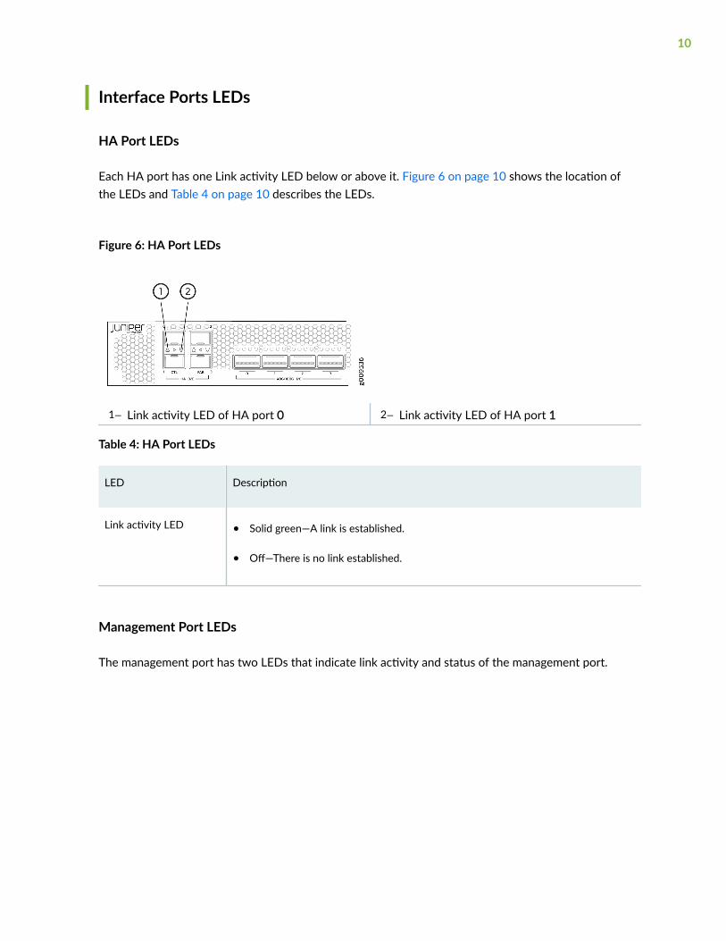
Interface Ports LEDs
HA Port LEDs
Each HA port has one Link activity LED below or above it. Figure 6 on page 10 shows the location ofthe LEDs and Table 4 on page 10 describes the LEDs.
Figure 6: HA Port LEDs
1— Link activity LED of HA port 0 2— Link activity LED of HA port 1
Table 4: HA Port LEDs
LED Description
Link activity LED • Solid green—A link is established.
• Off—There is no link established.
Management Port LEDs
The management port has two LEDs that indicate link activity and status of the management port.
10
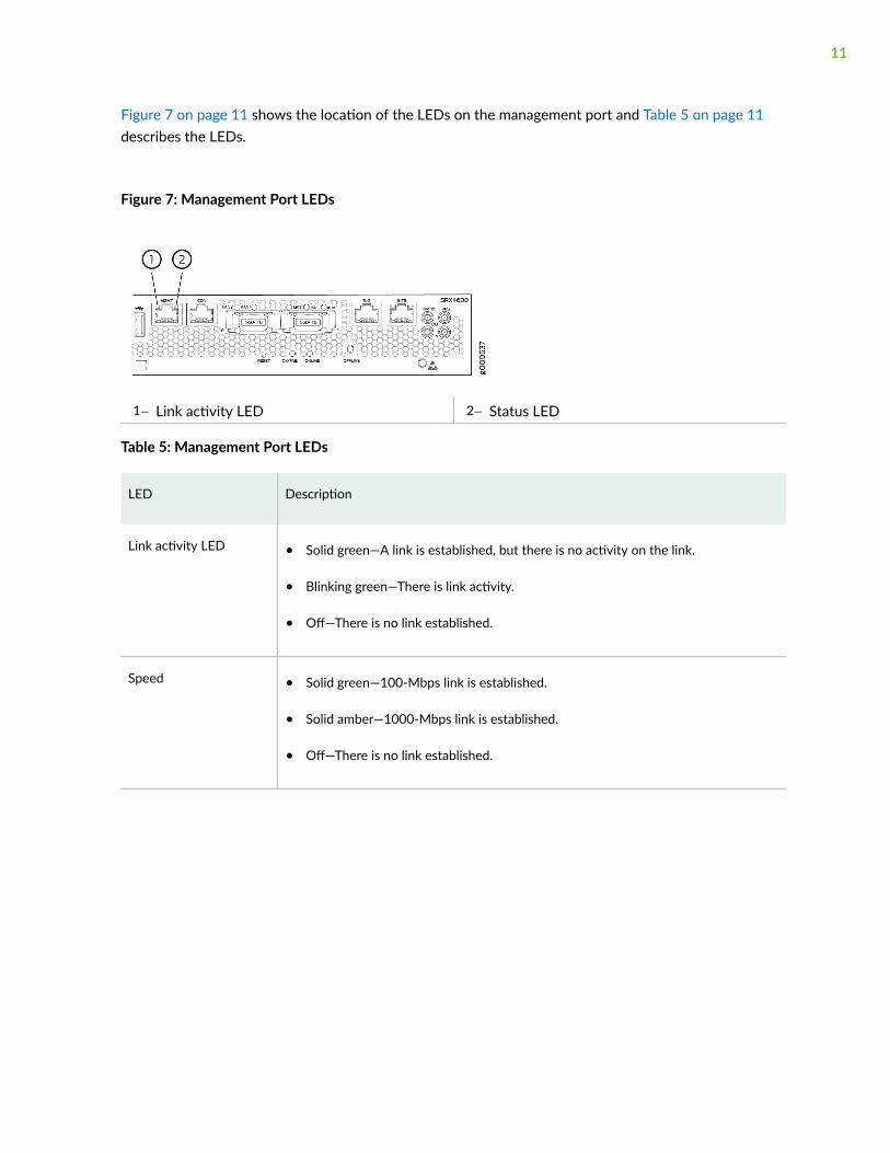
Figure 7 on page 11 shows the location of the LEDs on the management port and Table 5 on page 11describes the LEDs.
Figure 7: Management Port LEDs
1— Link activity LED 2— Status LED
Table 5: Management Port LEDs
LED Description
Link activity LED • Solid green—A link is established, but there is no activity on the link.
• Blinking green—There is link activity.
• Off—There is no link established.
Speed • Solid green—100-Mbps link is established.
• Solid amber—1000-Mbps link is established.
• Off—There is no link established.
11

Network Port LEDs
Each QSFP28 port has one link activity LED above it and each SFP+ port has one link activity LEDlocated above or below it. Figure 8 on page 12 shows the location of the LEDs and Table 6 on page12 describes the LEDs.
Figure 8: Network Port LEDs
1— Link activity LED of QSFP28 port 0 3— Link activity LED of SFP+ port 1
2— Link activity LED of SFP+ port 0
Table 6: Network Port LEDs
LED Description
Link activity LED • Solid green—There is link activity.
• Off—There is no link established.
Port and Interface Numbering
Each port on the services gateway corresponds to a unique interface name in the CLI. The four Chassiscluster (HA) ports (referred to as PIC 0 ports of FPC 0), four 40/100-Gigabit Ethernet QSFP28 (quadsmall form-factor pluggable) ports (referred to as PIC 0 ports of FPC 1), and eight 1/10-Gigabit EthernetSFP+ ports (referred to as PIC 1 ports of FPC 1). Figure 9 on page 13 shows the SRX4600 InterfacePort numbering.
In the syntax of an interface name, a hyphen (-) separates the media type from the FPC slot number(represented as an FPC in the CLI). The FPC slot number corresponds to the first number in the interface.The second number in the interface corresponds to the PIC number. The last number in the interfacematches the port number on the PIC. Slashes (/) separate the FPC number from the PIC number andport number:
12
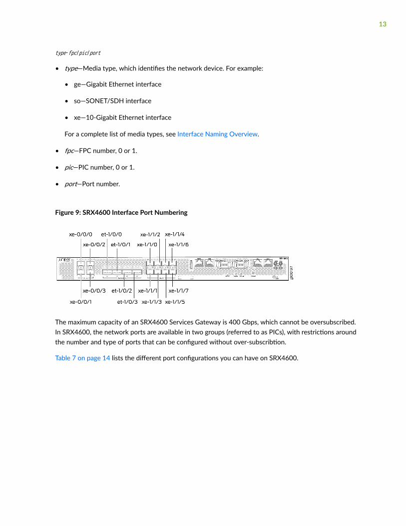
type-fpc/pic/port
• type—Media type, which identifies the network device. For example:
• ge—Gigabit Ethernet interface
• so—SONET/SDH interface
• xe—10-Gigabit Ethernet interface
For a complete list of media types, see Interface Naming Overview.
• fpc—FPC number, 0 or 1.
• pic—PIC number, 0 or 1.
• port—Port number.
Figure 9: SRX4600 Interface Port Numbering
The maximum capacity of an SRX4600 Services Gateway is 400 Gbps, which cannot be oversubscribed.In SRX4600, the network ports are available in two groups (referred to as PICs), with restrictions aroundthe number and type of ports that can be configured without over-subscribtion.
Table 7 on page 14 lists the different port configurations you can have on SRX4600.
13

Table 7: SRX4600 Services Gateway Port Configurations
InterfaceOptions
PIC0 PIC1
1/0/0 1/0/1 1/0/2 1/0/3 1/1/0
1/1/1
1/1/2
1/1/3
1/1/4
1/1/5
1/1/6
1/1/7
1 4x10G
or
1x40G
4x10G
or
1x40G
4x10G
or
1x40G
4x10G
or
1x40G
1G
or
10G
1G
or
10G
1G
or
10G
1G
or
10G
1G
or
10G
1G
or
10G
1G
or
10G
1G
or
10G
2 100G 100G 4x10G
or
1x40G
4x10G
or
1x40G
1G
or
10G
1G
or
10G
1G
or
10G
1G
or
10G
1G
or
10G
1G
or
10G
1G
or
10G
1G
or
10G
3 100G 100G 100G 100G - - - - - - - -
For information on port configurations and rate-selectability, see SRX4600 Port Speed Overview and"Understanding the SRX4600 Services Gateway Chassis" on page 4.
Chassis Rear Panel
Figure 10 on page 14 shows the rear panel of the SRX4600 Services Gateway with AC power supplies.
Figure 10: Rear Panel of the SRX4600 Services Gateway with AC Power Supplies
1— Fan modules 2— AC power supplies
14

Figure 11 on page 15 shows the rear panel of the SRX4600 Services Gateway with DC power supplies.
Figure 11: Rear Panel of the SRX4600 Services Gateway with DC Power Supplies
1— Fan modules 2— DC power supplies
Table 8 on page 15 lists and describes the rear panel components of the services gateway.
Table 8: SRX4600 Services Gateway Components on the Rear Panel
Component Description
Fan modules Five airflow out (AFO) fan modules (4+1 redundancy).
Five fan modules for cooling the services gateway and its components. Four fanmodules are required for proper air flow across the chassis internal components. Thefifth fan module provides redundancy.
PSUs (Power SupplyUnits)
Two power supply slots. Two 1600W AC or two 1100W DC power supply units (1+1redundancy) are provided with the services gateway.
Understanding the SRX4600 Services GatewayCooling System and Air Flow
IN THIS SECTION
Fan Module | 16
Fan Module LEDs | 17
15
Airflow Through Chassis | 18
The cooling system in an SRX4600 Services Gateway consists of five fan modules (4+1 redundancy)located at the rear of the chassis.
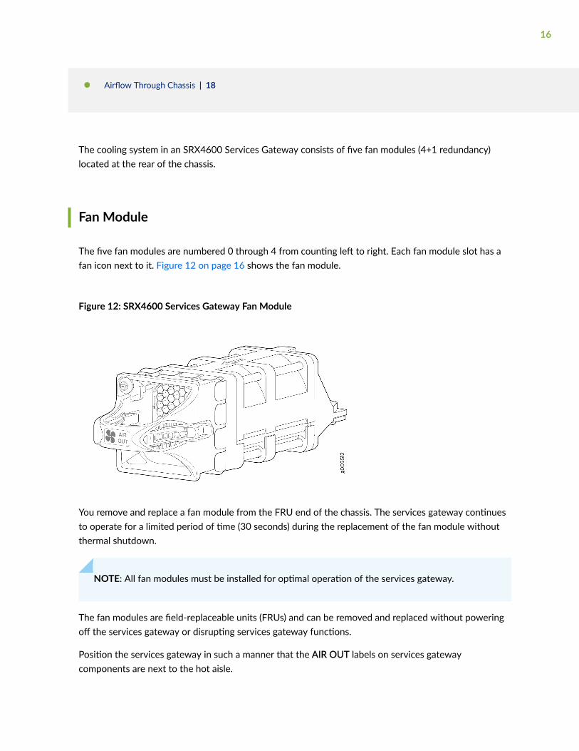
Fan Module
The five fan modules are numbered 0 through 4 from counting left to right. Each fan module slot has afan icon next to it. Figure 12 on page 16 shows the fan module.
Figure 12: SRX4600 Services Gateway Fan Module
You remove and replace a fan module from the FRU end of the chassis. The services gateway continuesto operate for a limited period of time (30 seconds) during the replacement of the fan module withoutthermal shutdown.
NOTE: All fan modules must be installed for optimal operation of the services gateway.
The fan modules are field-replaceable units (FRUs) and can be removed and replaced without poweringoff the services gateway or disrupting services gateway functions.
Position the services gateway in such a manner that the AIR OUT labels on services gatewaycomponents are next to the hot aisle.
16

Under normal operating conditions, the fan modules operate at a moderate speed. Temperature sensorsin the chassis monitor the temperature within the chassis.
Fan Module LEDs
Each fan module has a LED next to it.
Figure 13 on page 17 shows the location of the LED next to the fan module.
Figure 13: Location of Fan Module LED in an SRX4600 Services Gateway
1— Fan module LED
Table 9 on page 17 describes the function of the fan module LED.
Table 9: Fan Module LED
Name Color State Description
Fan Green On steadily The fan module is operating normally. The system has verified that the module isengaged, that the airflow is in the correct direction, and that the fan is operatingcorrectly.
Amber Blinking An error has been detected in the fan module. Replace the fan module as soon aspossible. Either the fan has failed or it is seated incorrectly. To maintain properairflow through the chassis, leave the fan module installed in the chassis untilyou are ready to replace it.
17

CAUTION: The system raises an alarm if a fan module fails or if the ambienttemperature inside the chassis rises above the acceptable range. If the temperatureinside the chassis rises above the threshold temperature, the system shuts downautomatically.
Airflow Through Chassis
The direction of airflow in the chassis is from Port-to-FRU, that is, air comes in through vents on the endwith ports and air exhausts out the end with the fans (also known as front-to-back airflow). See Figure14 on page 18.
Figure 14: Airflow Through Chassis
The airflow out (AFO) fan modules draw air through vents on the front of the services gateway chassisand exhaust the air through the back of the chassis.
RELATED DOCUMENTATION
Clearance Requirements for Airflow and Hardware Maintenance for SRX4600 Services Gateways | 32
18
Maintaining the SRX4600 Cooling System | 71
SRX4600 Power System
IN THIS SECTION
Understanding the SRX4600 Services Gateway Power Supply | 19
SRX4600 Services Gateway AC Power Supply Specifications | 23
SRX4600 Services Gateway AC Power Cord Specifications | 24
SRX4600 Services Gateway DC Power Supply Specifications | 26
Understanding the SRX4600 Services Gateway Power Supply
IN THIS SECTION
AC Power Supply | 19
DC Power Supply | 21
The SRX4600 Services Gateway ships with two AC or two DC power supplies (1+1 redundancy)preinstalled in the rear panel of the chassis in slots labeled 0 and 1. The SRX4600 Services Gatewaypower supply is a field-replaceable unit (FRU) and you can install it without powering off the servicesgateway or disrupting the services gateway function.
AC Power Supply
The AC power supply is a FRU and you can install it without powering off the services gateway ordisrupting the services gateway function.
Each AC power supply weighs approximately 3.4 lb (1.54 kg) and consists of a handle, an ejection lever,an AC appliance inlet, an internal fan, and an LED to monitor the status of the power supply. The ACpower supply supports both low-voltage line (800 W) and high-voltage line (1600 W).
19
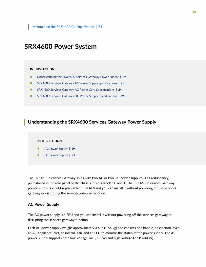
Each inlet requires a dedicated AC power feed and a dedicated customer-site circuit breaker. Werecommend that you use a minimum 15 A (110 VAC) customer-site circuit breaker, or as required bylocal code. Figure 15 on page 20 shows the AC power supply.
Figure 15: SRX4600 Services Gateway AC Power Supply
Each AC power supply provides power to all components in the services gateway. The two powersupplies provide full power redundancy to the services gateway. If one power supply fails or is removed,the second power supply balances the electrical load without interruption. The services gatewayreassesses the power required to support the services gateway configuration and issues error messagesif the available power is insufficient.
For instructions on installing the power supply, see "Installing the SRX4600 Services Gateway AC PowerSupply" on page 77.
WARNING: The services gateway is pluggable type A equipment installed in arestricted-access location. It has a separate protective earthing terminal provided on thechassis in addition to the grounding pin of the power supply cord. This separateprotective earthing terminal must be permanently connected to earth ground. See"Connecting Earth Ground to an SRX4600 Services Gateway" on page 59.
20
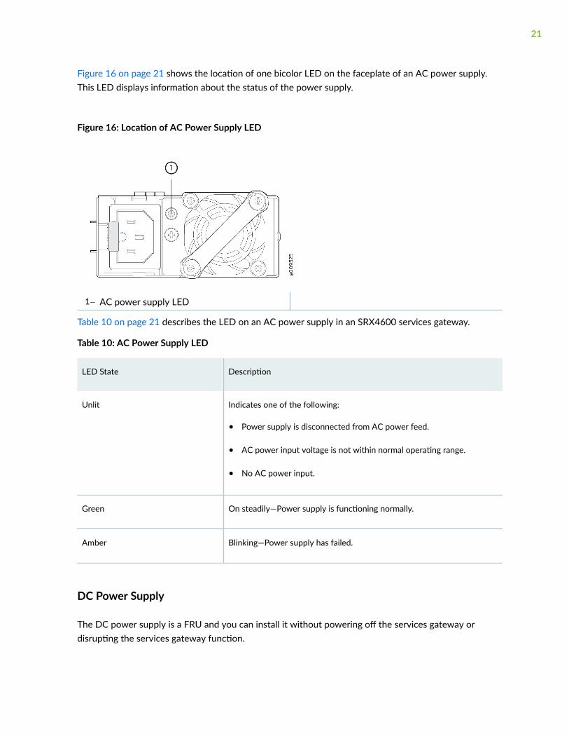
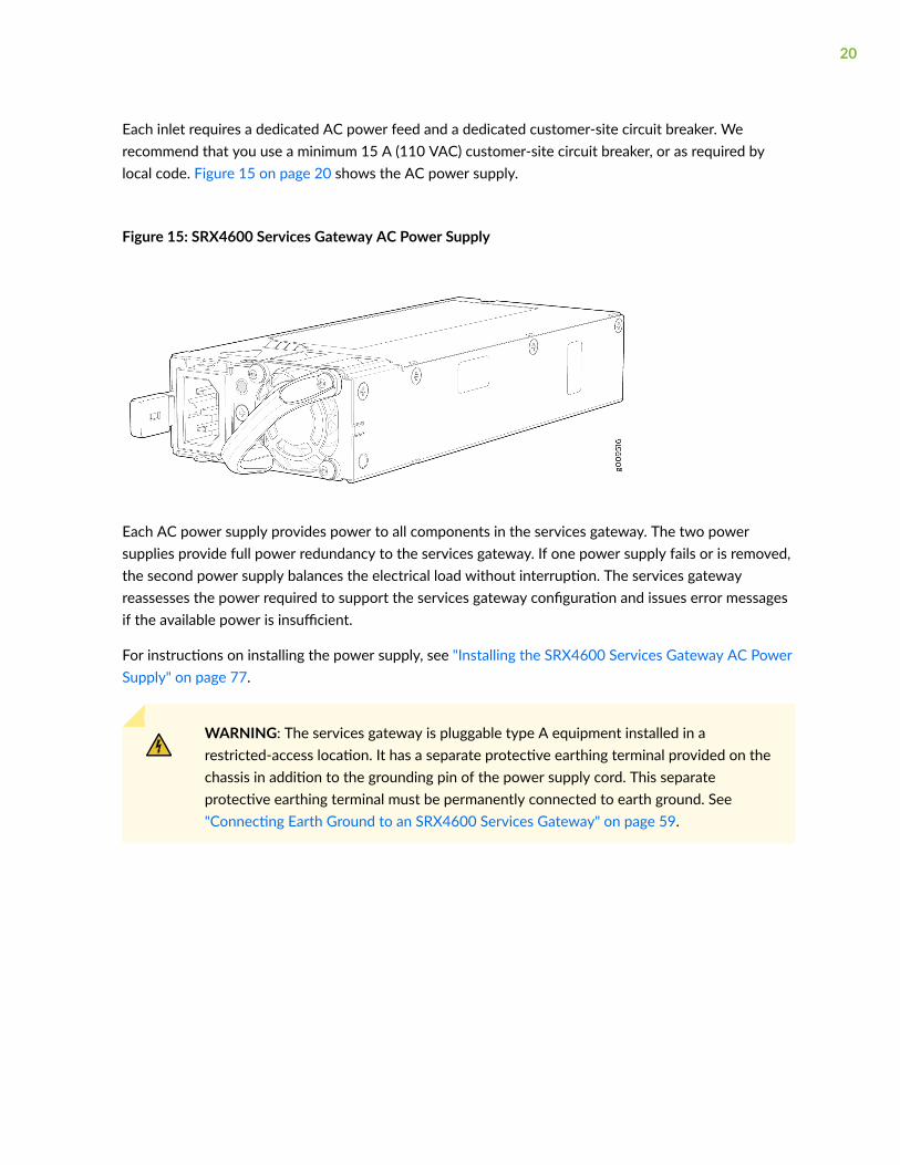
Figure 16 on page 21 shows the location of one bicolor LED on the faceplate of an AC power supply.This LED displays information about the status of the power supply.
Figure 16: Location of AC Power Supply LED
1— AC power supply LED
Table 10 on page 21 describes the LED on an AC power supply in an SRX4600 services gateway.
Table 10: AC Power Supply LED
LED State Description
Unlit Indicates one of the following:
• Power supply is disconnected from AC power feed.
• AC power input voltage is not within normal operating range.
• No AC power input.
Green On steadily—Power supply is functioning normally.
Amber Blinking—Power supply has failed.
DC Power Supply
The DC power supply is a FRU and you can install it without powering off the services gateway ordisrupting the services gateway function.
21
Each DC power supply weighs approximately 4.4 lb (1.99 kg) and consists of a handle, an ejection lever,a status LED, and a terminal block that provides a single DC input (–48 VDC and return) that requires adedicated customer-site circuit breaker. We recommend that you use a dedicated customer-site circuitbreaker rated for 15 A (–48 VDC) minimum, or as required by local code. The DC power supply gives anoutput of 1100 W. Figure 17 on page 22 shows the DC power supply.
Figure 17: SRX4600 Services Gateway DC Power Supply
Each DC power supply provides power to all components in the services gateway. The two powersupplies provide full power redundancy to the services gateway. If one power supply fails or is removed,the second power supply balances the electrical load without interruption. The services gatewayreassesses the power required to support the services gateway configuration and issues error messagesif the available power is insufficient.
For instructions on installing the power supply, see "Installing the SRX4600 Services Gateway DC PowerSupply" on page 80.
22

Figure 18 on page 23 shows the location of one bicolor LED on the faceplate of an DC power supply.This LED displays information about the status of the power supply.
Figure 18: Location of DC Power Supply LED
1— DC power supply LED
Table 11 on page 23 describes the LED on a DC power supply in an SRX4600 services gateway.
Table 11: DC Power Supply LED
LED State Description
Unlit Indicates one of the following:
• Power supply is disconnected from DC power feed.
• DC power input voltage is not within normal operating range.
• No DC power input.
Green On steadily—Power supply is functioning normally.
Amber Blinking—Power supply has failed.
SRX4600 Services Gateway AC Power Supply Specifications
Table 12 on page 24 lists the specifications for an AC power supply.
23

Table 12: AC Power Supply Specifications
Item Specification
AC input voltage Operating range:
• Low-voltage line: 110–127 VAC
• High-voltage line: 200–240 VAC
AC input line frequency 50–60 Hz
AC input current rating • Low-voltage line: 10.8 A
• High-voltage line: 10.8 A
AC output power • Low-voltage line: 800 W
• High-voltage line: 1600 W
Maximum System Power Requirement ~800 W
System Thermal Output = (Maximum System Power Requirement ) * 3.41
Note: 1 W = 3.41 BTU/Hour
2728 BTU/Hour
SRX4600 Services Gateway AC Power Cord Specifications
A detachable AC power cord is supplied with the AC power supplies. The coupler is type C13 asdescribed by International Electrotechnical Commission (IEC) standard 60320. The plug end of thepower cord fits into the power source outlet that is standard for your geographical location.
NOTE: In North America, AC power cords must not exceed 4.5 m (approximately 14.75 ft) inlength, to comply with National Electrical code (NEC) Section 400-8 (NFPA 75, 5-2.2) and
24

210-52, and Canadian Electrical Code (CEC) Section 4-010(3). The cords supplied with theservices gateway are in compliance.
Table 13 on page 25 provides power cord specifications, and Figure 19 on page 25 depicts the plugon the AC power cord provided for each country or region.
Table 13: AC Power Cord Specifications
Country Electrical Specification Plug Standards
Australia 250 VAC, 10 A, 50 Hz AS/NZ 3112-1993
China 250 VAC, 10 A, 50 Hz GB2099.1 1996 and GB1002 1996 (CH1-10P)
Europe (except Italy and United Kingdom) 250 VAC, 10 A, 50 Hz CEE (7) VII
Italy 250 VAC, 10 A, 50 Hz CEI 23-16/VII
Japan 125 VAC, 12 A, 50 or 60 Hz JIS 8303
North America 125 VAC, 10 A, 60 Hz NEMA 5-15
United Kingdom 250 VAC, 10 A, 50 Hz BS 1363A
Figure 19: AC Plug Types
25

NOTE: Power cords and cables must not block access to services gateway components or drapewhere people might trip on them.
CAUTION: The AC power cord for the services gateway is intended for use with theservices gateway only and not for any other use.
SRX4600 Services Gateway DC Power Supply Specifications
Table 14 on page 26 lists the power supply specifications for a DC power supply.
Table 14: DC Power Supply Specifications
Item Specifications
DC input voltage • Minimum operating voltage: –40 VDC
• Nominal operating voltage: –48 VDC
• Operating voltage range: –40 VDC through –72 VDC
DC input current rating 32 A @ –48 VDC
Output power 1100 W
RELATED DOCUMENTATION
Maintaining the SRX4600 Power System | 75
26

2CHAPTER
Site Planning, Preparation, andSpecifications
Site Preparation Checklist for the SRX4600 Services Gateway | 28
SRX4600 Site Guidelines and Requirements | 30
SRX4600 Rack and Cabinet Requirements | 34
SRX4600 Alarm and Management Cable Specifications and Pinouts | 37
Site Preparation Checklist for the SRX4600 ServicesGateway
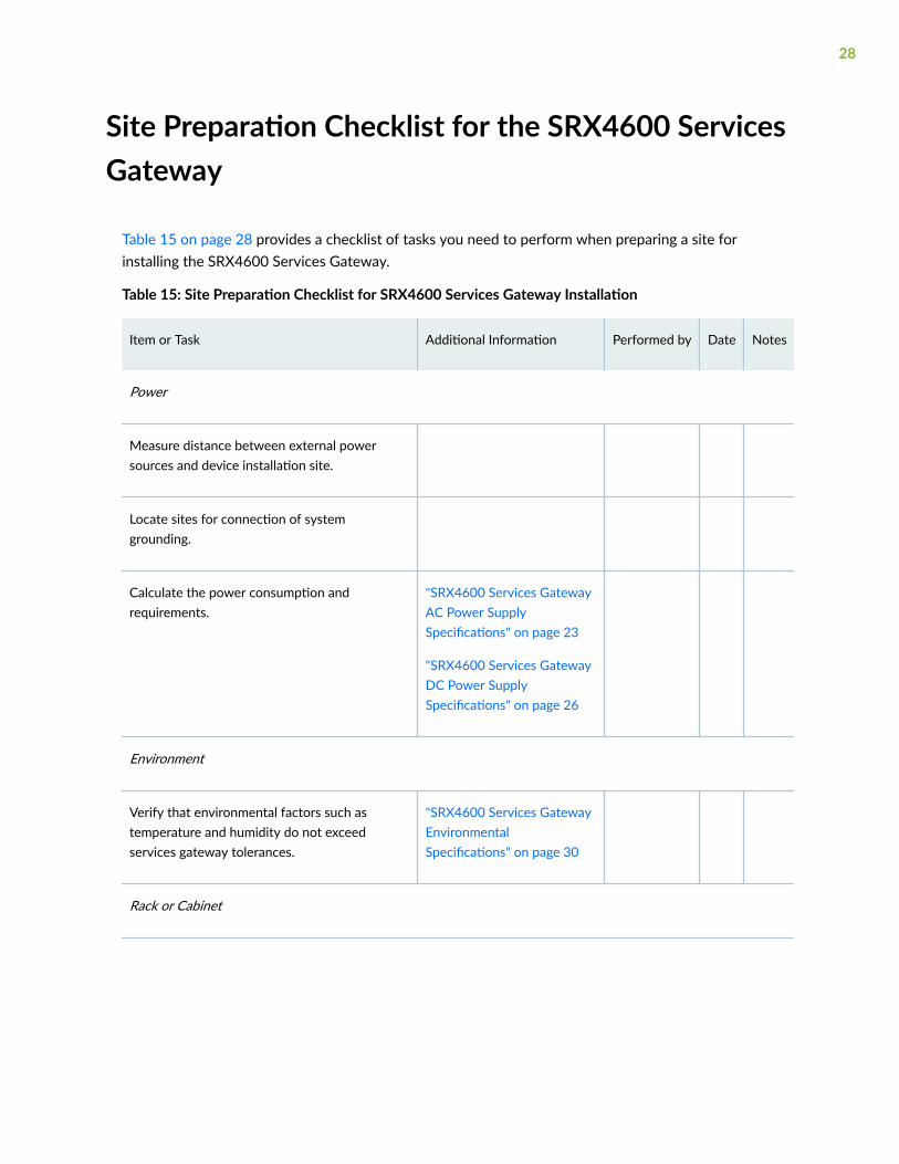
Table 15 on page 28 provides a checklist of tasks you need to perform when preparing a site forinstalling the SRX4600 Services Gateway.
Table 15: Site Preparation Checklist for SRX4600 Services Gateway Installation
Item or Task Additional Information Performed by Date Notes
Power
Measure distance between external powersources and device installation site.
Locate sites for connection of systemgrounding.
Calculate the power consumption andrequirements.
"SRX4600 Services GatewayAC Power SupplySpecifications" on page 23
"SRX4600 Services GatewayDC Power SupplySpecifications" on page 26
Environment
Verify that environmental factors such astemperature and humidity do not exceedservices gateway tolerances.
"SRX4600 Services GatewayEnvironmentalSpecifications" on page 30
Rack or Cabinet
28

Table 15: Site Preparation Checklist for SRX4600 Services Gateway Installation (Continued)
Item or Task Additional Information Performed by Date Notes
Verify that your rack or cabinet meets theminimum requirements for the installation ofthe device.
"SRX4600 Services GatewayRack Requirements" on page34
"Cabinet Requirements" onpage 36
Plan rack location, including required spaceclearances.
Secure the rack or cabinet to the floor andbuilding structure.
Cables
Acquire cables and connectors:
• Determine the number of cables neededbased on your planned configuration.
• Review the maximum distance allowed foreach cable. Choose the length of cablebased on the distance between thehardware components being connected.
Plan the cable routing and management.
RELATED DOCUMENTATION
SRX4600 Services Gateway Installation Overview | 49
29
SRX4600 Site Guidelines and Requirements
IN THIS SECTION
SRX4600 Services Gateway Environmental Specifications | 30
General Site Guidelines | 31
Site Electrical Wiring Guidelines | 31
Clearance Requirements for Airflow and Hardware Maintenance for SRX4600 Services Gateways | 32
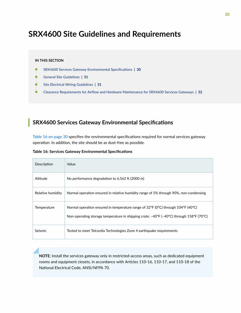
SRX4600 Services Gateway Environmental Specifications
Table 16 on page 30 specifies the environmental specifications required for normal services gatewayoperation. In addition, the site should be as dust-free as possible.
Table 16: Services Gateway Environmental Specifications
Description Value
Altitude No performance degradation to 6,562 ft (2000 m)
Relative humidity Normal operation ensured in relative humidity range of 5% through 90%, non-condensing
Temperature Normal operation ensured in temperature range of 32°F (0°C) through 104°F (40°C)
Non-operating storage temperature in shipping crate: –40°F (–40°C) through 158°F (70°C)
Seismic Tested to meet Telcordia Technologies Zone 4 earthquake requirements
NOTE: Install the services gateway only in restricted-access areas, such as dedicated equipmentrooms and equipment closets, in accordance with Articles 110-16, 110-17, and 110-18 of theNational Electrical Code, ANSI/NFPA 70.
30
General Site Guidelines
Efficient device operation requires proper site planning and maintenance and proper layout of theequipment, rack or cabinet, and wiring closet.
To plan and create an acceptable operating environment for your device and prevent environmentallycaused equipment failures:
• Keep the area around the chassis free from dust and conductive material, such as metal flakes.
• Follow prescribed airflow guidelines to ensure that the cooling system functions properly and thatexhaust from other equipment does not blow into the intake vents of the device.
• Follow the prescribed electrostatic discharge (ESD) prevention procedures to prevent damaging theequipment. Static discharge can cause components to fail completely or intermittently over time.
• Install the device in a secure area, so that only authorized personnel can access the device.
Site Electrical Wiring Guidelines
Table 17 on page 32 describes the factors you must consider while planning the electrical wiring atyour site.
WARNING: You must provide a properly grounded and shielded environment and useelectrical surge-suppression devices.
Avertissement Vous devez établir un environnement protégé et convenablement mis àla terre et utiliser des dispositifs de parasurtension.
31
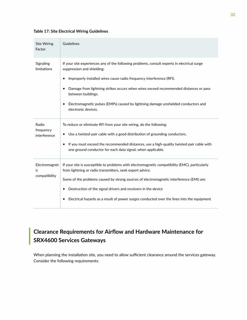
Table 17: Site Electrical Wiring Guidelines
Site WiringFactor
Guidelines
Signalinglimitations
If your site experiences any of the following problems, consult experts in electrical surgesuppression and shielding:
• Improperly installed wires cause radio frequency interference (RFI).
• Damage from lightning strikes occurs when wires exceed recommended distances or passbetween buildings.
• Electromagnetic pulses (EMPs) caused by lightning damage unshielded conductors andelectronic devices.
Radiofrequencyinterference
To reduce or eliminate RFI from your site wiring, do the following:
• Use a twisted-pair cable with a good distribution of grounding conductors.
• If you must exceed the recommended distances, use a high-quality twisted-pair cable withone ground conductor for each data signal, when applicable.
Electromagneticcompatibility
If your site is susceptible to problems with electromagnetic compatibility (EMC), particularlyfrom lightning or radio transmitters, seek expert advice.
Some of the problems caused by strong sources of electromagnetic interference (EMI) are:
• Destruction of the signal drivers and receivers in the device
• Electrical hazards as a result of power surges conducted over the lines into the equipment
Clearance Requirements for Airflow and Hardware Maintenance forSRX4600 Services Gateways
When planning the installation site, you need to allow sufficient clearance around the services gateway.Consider the following requirements:
32

• For the cooling system to function properly, the airflow around the chassis must be unrestricted. SeeFigure 20 on page 33.
Figure 20: Clearance Requirements for Airflow and Hardware Maintenance for an SRX4600Services Gateway Chassis
• If you are mounting the services gateway on a rack or cabinet along with other equipment, ensurethat the exhaust from other equipment does not blow into the intake vents of the chassis.
• For service personnel to remove and install hardware components, there must be adequate space atthe front and back of the services gateway as indicated in Table 18 on page 33.
Table 18 on page 33 provides information about the clearance requirements for maintaining optimumairflow and the distances necessary to facilitate easy maintenance of the services gateway.
Table 18: Clearance Requirements for the SRX4600 Services Gateway
Location RecommendedClearance
Requirement for Clearance
Front of the chassis 24.00 in. (60.90 cm) Space for service personnel to remove andinstall hardware components
33

Table 18: Clearance Requirements for the SRX4600 Services Gateway (Continued)
Location RecommendedClearance
Requirement for Clearance
Rear of the chassis 24.00 in. (60.90 cm) Space for service personnel to remove andinstall hardware components
Between front-mounting flange andrack or cabinet edge
2.50 in. (6.35 cm) Space for cable management andorganization
Between both sides of the chassis andany non-heat-producing surface suchas a wall or cabinet side
6.00 in. (15.24 cm) Space for the cooling system to functionproperly and to maintain unrestricted airflowaround the chassis
RELATED DOCUMENTATION
Understanding the SRX4600 Services Gateway Chassis | 4
SRX4600 Rack and Cabinet Requirements
IN THIS SECTION
SRX4600 Services Gateway Rack Requirements | 34
Cabinet Requirements | 36
SRX4600 Services Gateway Rack Requirements
You can mount the device on four-post racks.
Rack requirements consist of:
• Rack type
34

• Mounting bracket hole spacing
• Rack size and strength
• Rack connection to the building structure
Table 19 on page 35 provides the rack requirements and specifications.
Table 19: Rack Requirements and Specifications
Rack Requirement Guidelines
Rack type You can mount the device on a rack that provides bracket holes or holepatterns spaced at 1 U (1.75 in. or 4.45 cm) increments and meets the sizeand strength requirements to support the weight.
A U is the standard rack unit defined by the Electronics Industry Association.
Mounting bracket hole spacing The holes in the mounting brackets are spaced at 1 U (1.75 in. or 4.45 cm), sothat the device can be mounted in any rack that provides holes spaced at thatdistance.
Rack size and strength • Ensure that the rack complies with the size and strength standards of a19-in. rack as defined by the Electronics Industry Association.
• Ensure that the rack rails are spaced widely enough to accommodate theexternal dimensions of the device chassis. The outer edges of the front-mounting brackets extend the width of the chassis to 19 in. (48.2 cm).
Space the front and rear rack rails between 23.5 in (59.7 cm) to30.25 in (76.8 cm) front-to-back.
• The rack must be strong enough to support the weight of the device.
• Ensure that the spacing of rails and adjacent racks provides for properclearance around the device and rack.
Rack connection to buildingstructure
• Secure the rack to the building structure.
• If earthquakes are a possibility in your geographical area, secure the rackto the floor.
• Secure the rack to the ceiling brackets as well as wall or floor brackets formaximum stability.
35

Cabinet Requirements
You can mount the device in a cabinet that contains a 19-in. rack.
Cabinet requirements consist of:
• Cabinet size
• Clearance requirements
• Cabinet airflow requirements
Table 20 on page 36 provides the cabinet requirements and specifications.
Table 20: Cabinet Requirements and Specifications
Cabinet Requirement Guidelines
Cabinet size • The minimum cabinet size is 36 in. (91.4 cm) deep. Large cabinetsimprove airflow and reduce chances of overheating.
Cabinet clearance • The outer edges of the front mounting brackets extend the width of thechassis to 19 in. (48.2 cm).
• The minimum total clearance inside the cabinet is 30.7 in. (78 cm)between the inside of the front door and the inside of the rear door.
36
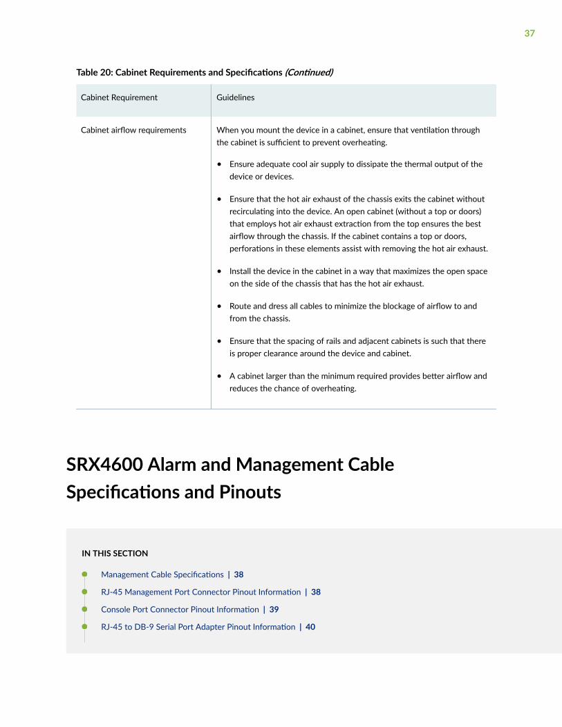
Table 20: Cabinet Requirements and Specifications (Continued)
Cabinet Requirement Guidelines
Cabinet airflow requirements When you mount the device in a cabinet, ensure that ventilation throughthe cabinet is sufficient to prevent overheating.
• Ensure adequate cool air supply to dissipate the thermal output of thedevice or devices.
• Ensure that the hot air exhaust of the chassis exits the cabinet withoutrecirculating into the device. An open cabinet (without a top or doors)that employs hot air exhaust extraction from the top ensures the bestairflow through the chassis. If the cabinet contains a top or doors,perforations in these elements assist with removing the hot air exhaust.
• Install the device in the cabinet in a way that maximizes the open spaceon the side of the chassis that has the hot air exhaust.
• Route and dress all cables to minimize the blockage of airflow to andfrom the chassis.
• Ensure that the spacing of rails and adjacent cabinets is such that thereis proper clearance around the device and cabinet.
• A cabinet larger than the minimum required provides better airflow andreduces the chance of overheating.
SRX4600 Alarm and Management CableSpecifications and Pinouts
IN THIS SECTION
Management Cable Specifications | 38
RJ-45 Management Port Connector Pinout Information | 38
Console Port Connector Pinout Information | 39
RJ-45 to DB-9 Serial Port Adapter Pinout Information | 40
37

RJ-45 Port, SFP Port, SFP+ Port, QSFP+ Port, and QSFP28 Port Connector Pinout Information | 41
Management Cable Specifications
Table 21 on page 38 lists the specifications for the cables that connect the console and managementports to management devices.
Table 21: Specifications of Cables to Connect to Management Devices
Ports Cable Specifications Receptacle Additional Information
RJ-45 Console port CAT5e UTP (unshieldedtwisted pair) cable
RJ-45 "Connect a Device to aManagement ConsoleUsing an RJ-45Connector" on page 55
Management Ethernetport
Ethernet cable with anRJ-45 connector
RJ-45 "Connect a Device to aNetwork for Out-of-BandManagement" on page57
Mini-USB Type-B Consoleport
Mini-USB cable withstandard-A and Mini-USBType-B (5-pin) connector
Mini-USB
RJ-45 Management Port Connector Pinout Information
Table 22 on page 39 provides the pinout information for the RJ-45 connector for the management porton Juniper Networks devices.
38

Table 22: RJ-45 Management Port Connector Pinout Information
Pin Signal Description
1 TRP1+ Transmit/receive data pair 1
2 TRP1— Transmit/receive data pair 1
3 TRP2+ Transmit/receive data pair 2
4 TRP3+ Transmit/receive data pair 3
5 TRP3— Transmit/receive data pair 3
6 TRP2— Transmit/receive data pair 2
7 TRP4+ Transmit/receive data pair 4
8 TRP4— Transmit/receive data pair 4
Console Port Connector Pinout Information
The console port on a Juniper Networks device is an RS-232 serial interface that uses an RJ-45connector to connect to a console management device. The default baud rate for the console port is9600 baud.
Table 23 on page 40 provides the pinout information for the RJ-45 console connector.
NOTE: If your laptop or desktop PC does not have a DB-9 plug connector pin and you want toconnect your laptop or desktop PC directly to a device, use a combination of the RJ-45 to DB-9socket adapter and a USB to DB-9 plug adapter. You must provide the USB to DB-9 plug adapter.
39
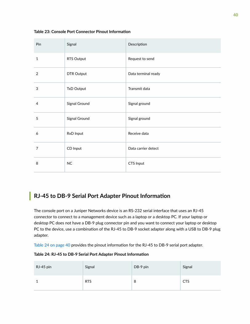
Table 23: Console Port Connector Pinout Information
Pin Signal Description
1 RTS Output Request to send
2 DTR Output Data terminal ready
3 TxD Output Transmit data
4 Signal Ground Signal ground
5 Signal Ground Signal ground
6 RxD Input Receive data
7 CD Input Data carrier detect
8 NC CTS Input
RJ-45 to DB-9 Serial Port Adapter Pinout Information
The console port on a Juniper Networks device is an RS-232 serial interface that uses an RJ-45connector to connect to a management device such as a laptop or a desktop PC. If your laptop ordesktop PC does not have a DB-9 plug connector pin and you want to connect your laptop or desktopPC to the device, use a combination of the RJ-45 to DB-9 socket adapter along with a USB to DB-9 plugadapter.
Table 24 on page 40 provides the pinout information for the RJ-45 to DB-9 serial port adapter.
Table 24: RJ-45 to DB-9 Serial Port Adapter Pinout Information
RJ-45 pin Signal DB-9 pin Signal
1 RTS 8 CTS
40
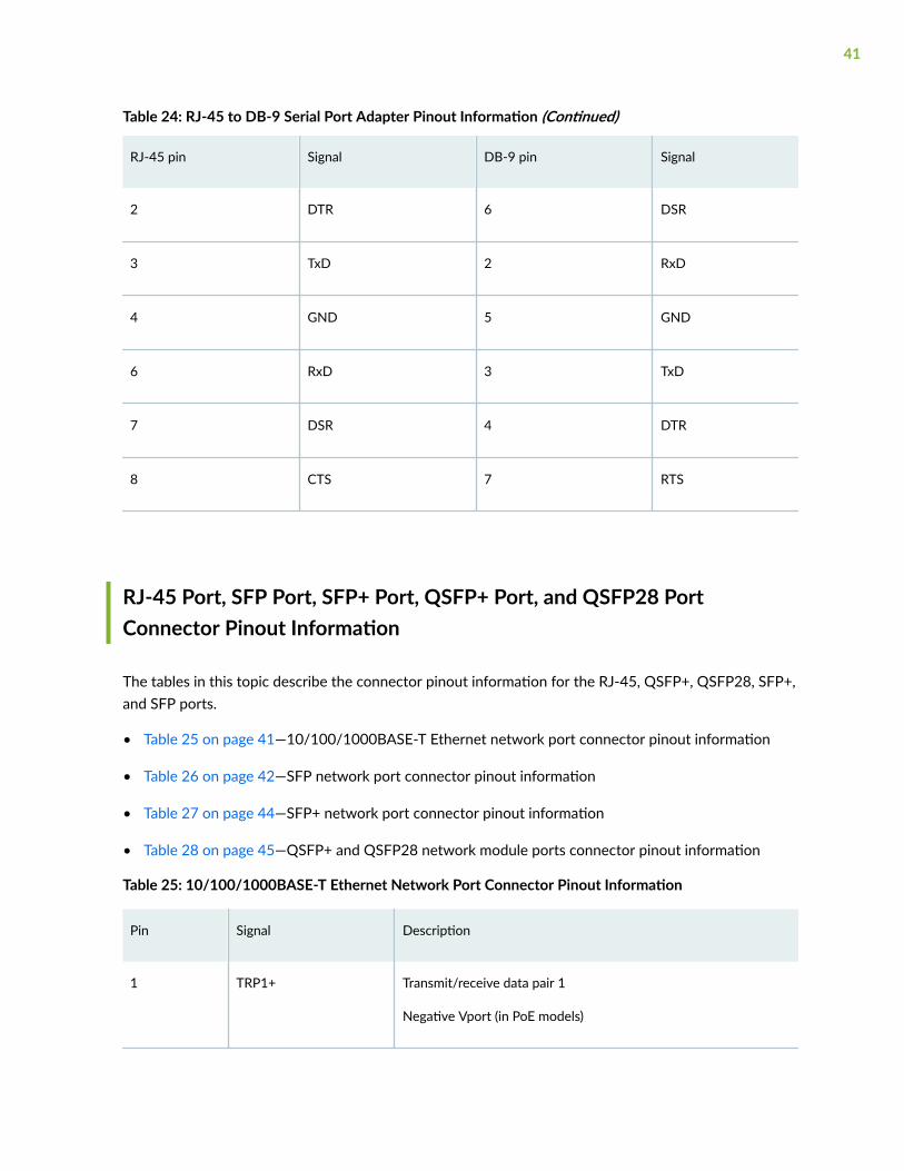
Table 24: RJ-45 to DB-9 Serial Port Adapter Pinout Information (Continued)
RJ-45 pin Signal DB-9 pin Signal
2 DTR 6 DSR
3 TxD 2 RxD
4 GND 5 GND
6 RxD 3 TxD
7 DSR 4 DTR
8 CTS 7 RTS
RJ-45 Port, SFP Port, SFP+ Port, QSFP+ Port, and QSFP28 PortConnector Pinout Information
The tables in this topic describe the connector pinout information for the RJ-45, QSFP+, QSFP28, SFP+,and SFP ports.
• Table 25 on page 41—10/100/1000BASE-T Ethernet network port connector pinout information
• Table 26 on page 42—SFP network port connector pinout information
• Table 27 on page 44—SFP+ network port connector pinout information
• Table 28 on page 45—QSFP+ and QSFP28 network module ports connector pinout information
Table 25: 10/100/1000BASE-T Ethernet Network Port Connector Pinout Information
Pin Signal Description
1 TRP1+ Transmit/receive data pair 1
Negative Vport (in PoE models)
41

Table 25: 10/100/1000BASE-T Ethernet Network Port Connector Pinout Information (Continued)
Pin Signal Description
2 TRP1- Transmit/receive data pair 1
Negative Vport (in PoE models)
3 TRP2+ Transmit/receive data pair 2
Positive Vport (in PoE models)
4 TRP3+ Transmit/receive data pair 3
5 TRP3- Transmit/receive data pair 3
6 TRP2- Transmit/receive data pair 2
Positive Vport (in PoE models)
7 TRP4+ Transmit/receive data pair 4
8 TRP4- Transmit/receive data pair 4
Table 26: SFP Network Port Connector Pinout Information
Pin Signal Description
1 VeeT Module transmitter ground
2 TX_Fault Module transmitter fault
3 TX_Disable Transmitter disabled
4 SDA 2-wire serial interface data line
5 SCL- 2-wire serial interface clock
42

Table 26: SFP Network Port Connector Pinout Information (Continued)
Pin Signal Description
6 MOD_ABS Module absent
7 RS Rate select
8 RX_LOS Receiver loss of signal indication
9 VeeR Module receiver ground
10 VeeR Module receiver ground
11 VeeR Module receiver ground
12 RD- Receiver inverted data output
13 RD+ Receiver noninverted data output
14 VeeR Module receiver ground
15 VccR Module receiver 3.3 V supply
16 VccT Module transmitter 3.3 V supply
17 VeeT Module transmitter ground
18 TD+ Transmitter noninverted data input
19 TD- Transmitter inverted data input
20 VeeT Module transmitter ground
43

Table 27: SFP+ Network Port Connector Pinout Information
Pin Signal Description
1 VeeT Module transmitter ground
2 TX_Fault Module transmitter fault
3 TX_Disable Transmitter disabled
4 SDA 2-wire serial interface data line
5 SCL- 2-wire serial interface clock
6 MOD_ABS Module absent
7 RS0 Rate select 0, optionally controls SFP+ module receiver
8 RX_LOS Receiver loss of signal indication
9 RS1 Rate select 1, optionally controls SFP+ transmitter
10 VeeR Module receiver ground
11 VeeR Module receiver ground
12 RD- Receiver inverted data output
13 RD+ Receiver noninverted data output
14 VeeR Module receiver ground
15 VccR Module receiver 3.3-V supply
44

Table 27: SFP+ Network Port Connector Pinout Information (Continued)
Pin Signal Description
16 VccT Module transmitter 3.3-V supply
17 VeeT Module transmitter ground
18 TD+ Transmitter noninverted data input
19 TD- Transmitter inverted data input
20 VeeT Module transmitter ground
Table 28: QSFP+ and QSFP28 Network Port Connector Pinout Information
Pin Signal
1 GND
2 TX2n
3 TX2p
4 GND
5 TX4n
6 TX4p
7 GND
8 ModSelL
9 LPMode_Reset
45

Table 28: QSFP+ and QSFP28 Network Port Connector Pinout Information (Continued)
Pin Signal
10 VccRx
11 SCL
12 SDA
13 GND
14 RX3p
15 RX3n
16 GND
17 RX1p
18 RX1n
19 GND
20 GND
21 RX2n
22 RX2p
23 GND
24 RX4n
46

Table 28: QSFP+ and QSFP28 Network Port Connector Pinout Information (Continued)
Pin Signal
25 RX4p
26 GND
27 ModPrsL
28 IntL
29 VccTx
30 Vcc1
31 Reserved
32 GND
33 TX3p
34 TX3n
35 GND
36 TX1p
37 TX1n
38 GND
47
3CHAPTER
Initial Installation and Configuration
SRX4600 Services Gateway Installation Overview | 49
Unpacking the SRX4600 | 49
Mounting an SRX4600 Services Gateway on Four Posts of a Rack or Cabinet | 51
Connecting the SRX4600 to External Devices | 55
Connecting the SRX4600 to Power | 59
Configuring the SRX4600 Services Gateway | 66

SRX4600 Services Gateway Installation Overview
To install and connect an SRX4600 Services Gateway:
1. Follow instructions in "Unpacking the SRX4600 Services Gateway" on page 50.
2. Mount the services gateway by following instructions appropriate for your site:
• "Mounting an SRX4600 Services Gateway on Four Posts of a Rack or Cabinet" on page 51
3. Connect the grounding cable as described in "Connecting Earth Ground to an SRX4600 ServicesGateway" on page 59.
4. Follow instructions for connecting power as appropriate for your site. See:
• "Connecting AC Power to an SRX4600 Services Gateway" on page 61
• "Connecting DC Power to an SRX4600 Services Gateway" on page 63
5. Perform initial configuration by following the instructions in "Configuring the SRX4600 ServicesGateway" on page 66.
RELATED DOCUMENTATION
SRX4600 Site Guidelines and Requirements | 30
SRX4600 Rack and Cabinet Requirements | 34
Unpacking the SRX4600
IN THIS SECTION
Unpacking the SRX4600 Services Gateway | 50
Verifying Parts Received with the SRX4600 Services Gateway | 50
49

Unpacking the SRX4600 Services Gateway
The services gateway is shipped in a cardboard carton, secured with foam packing material. The cartonalso contains an accessory box and quick-start instructions.
CAUTION: The services gateway is maximally protected inside the cardboard carton.Do not unpack it until you are ready to begin installation.
To unpack the services gateway:
1. Move the cardboard carton to a staging area as close to the installation site as possible, where youhave enough room to remove the components from the chassis.
2. Open the carton.
3. Pull out the packing material holding the services gateway in place.
4. Verify the parts received against the inventory (packing list). The packing list specifies the partnumbers and carries a brief description of each part in your order.
5. Save the shipping carton and packing materials in case you need to move or ship the servicesgateway at a later time.
Verifying Parts Received with the SRX4600 Services Gateway
A packing list is included in each shipment. Check the parts in the shipment against the items on thepacking list. The packing list specifies the part numbers and descriptions of each part in your order.
If any part on the packing list is missing, contact your customer service representative or contact Junipercustomer care from within the U.S. or Canada by telephone at 1-888-314-5822. For international-dial ordirect-dial options in countries without toll-free numbers, see https://www.juniper.net/support/requesting-support.html.
NOTE: The parts shipped with your services gateway can vary depending on the configurationyou ordered.
Table 29 on page 51 lists the parts and their quantities in the packing list.
50

Table 29: Parts List for a Fully Configured Services Gateway
Component Quantity
Services gateway 1
Power supply (preinstalled) 2 AC or DC
AC power cord appropriate for your geographical location (only for AC models) 2
Four-post rack mounting kit 1
End User License Agreement 1
Documentation Roadmap Card 1
Safety Guide 1
USB flash drive with Junos OS 1
DB-9 to RJ-45 cable 1
Mounting an SRX4600 Services Gateway on FourPosts of a Rack or Cabinet
Before mounting the services gateway on four posts of a rack:
• Verify that the site meets the requirements described in "Site Preparation Checklist for the SRX4600Services Gateway" on page 28.
• Place the rack in its permanent location, allowing adequate clearance for airflow and maintenance,and secure it to the building structure.
51

• Read General Safety Guidelines and Warnings, with particular attention to Chassis and ComponentLifting Guidelines.
Ensure that you have the following parts and tools available:
• Phillips (+) screwdriver, number 2
• Six Phillips 4-40 flat-head mounting screws (provided with the four-post rack-mount kit)
• Eight Phillips 4x6-mm flat-head mounting screws (provided with the four-post rack-mount kit)
• One pair each of flush or 2-in.-recess front-mounting brackets
• One pair of side mounting rails
• One pair of rear mounting blades
• Screws to secure the chassis and the rear mounting blades to the rack (not provided)
You can mount an SRX4600 services gateway on four posts of a 19-in. rack or cabinet by using the four-post rack-mount kit. The remainder of this topic uses rack to mean rack or cabinet.
Space the front and rear rack rails between 23.5 in (59.7 cm) to 30.25 in (76.8 cm) front-to-back.
NOTE: One person must be available to lift the services gateway while another secures it to therack.
CAUTION: If you are mounting multiple units on a rack, mount the heaviest unit at thebottom of the rack and mount the other units from the bottom of the rack to the top indecreasing order of the weight of the units.
To mount the services gateway on four posts of a rack:
1. Remove the services gateway from the shipping carton (see "Unpacking the SRX4600 ServicesGateway" on page 50).
52

2. Attach the front-mounting brackets (either the flush or the 2-in.-recess brackets) to the sidemounting rails by using 6 Phillips 4-40 flat-head mounting screws. See Figure 21 on page 53.
Figure 21: Attaching the Front-Mounting Bracket to the Side Mounting Rail
1— Side mounting rail 2— Front-mounting bracket
3. Place the services gateway on a flat, stable surface.
4. Align the side mounting rails along the side panels of the services gateway chassis. Align the twoholes in the rear of the side mounting rails with the two holes on the rear of the side panel.
5. Insert the Phillips 4x6-mm flat-head mounting screws into the two aligned holes and tighten thescrews. Ensure that the two holes in the rear of the side mounting rails are aligned with theremaining two holes in the side panel. See Figure 22 on page 53.
Figure 22: Attaching the Side Mounting-Rail to the Services Gateway Chassis
53

6. Insert the Phillips 4x6-mm flat-head mounting screws into the remaining two holes in the sidemounting-rails and tighten the screws.
7. Have one person grasp both sides of the services gateway, lift the services gateway, and position itin the rack, aligning the side mounting rail holes with the threaded holes in the front post of therack. Align the bottom hole in both the front-mounting brackets with a hole in each rack rail,making sure that the chassis is level. See Figure 23 on page 54.
Figure 23: Mounting the Services Gateway to the Front Posts of a Rack
8. Have a second person secure the front of the services gateway to the rack by using the appropriatescrews for your rack.
9. Slide the rear mounting blades into the side mounting rails. See Figure 24 on page 54.
Figure 24: Sliding the Rear Mounting-Blades into the Side Mounting Rail
10. Attach the rear mounting blades to the rear post by using the appropriate screws for your rack.Tighten the screws.
11. Ensure that the services gateway chassis is level by verifying that all the screws on the front of therack are aligned with the screws at the back of the rack.
54
RELATED DOCUMENTATION
Connecting the SRX4600 to External Devices | 55
Connecting the SRX4600 to Power | 59
Connecting the SRX4600 to External Devices
IN THIS SECTION
Connect a Device to a Management Console Using an RJ-45 Connector | 55
Connect a Device to a Network for Out-of-Band Management | 57
Connecting an SRX4600 Services Gateway to a Management Console by Using the Mini-USB Type-BConsole Port | 58
Connect a Device to a Management Console Using an RJ-45 Connector
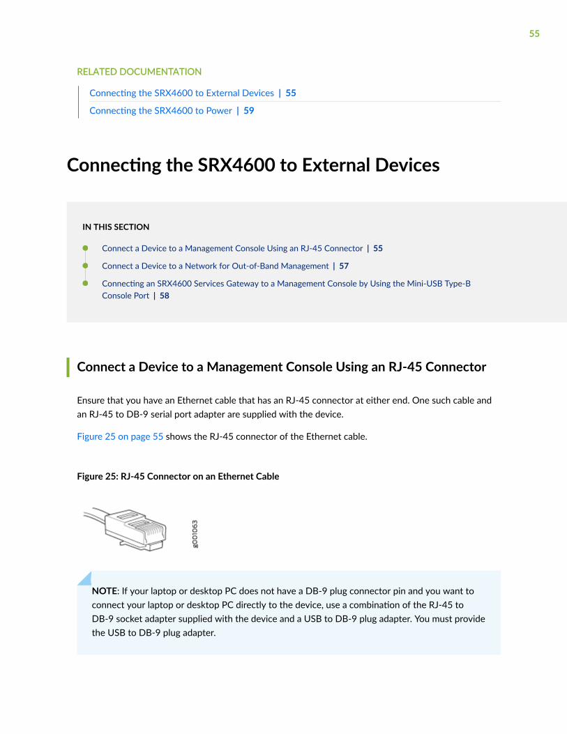
Ensure that you have an Ethernet cable that has an RJ-45 connector at either end. One such cable andan RJ-45 to DB-9 serial port adapter are supplied with the device.
Figure 25 on page 55 shows the RJ-45 connector of the Ethernet cable.
Figure 25: RJ-45 Connector on an Ethernet Cable
NOTE: If your laptop or desktop PC does not have a DB-9 plug connector pin and you want toconnect your laptop or desktop PC directly to the device, use a combination of the RJ-45 toDB-9 socket adapter supplied with the device and a USB to DB-9 plug adapter. You must providethe USB to DB-9 plug adapter.
55

You can configure and manage devices using a dedicated management channel. Each device has aconsole port which you can connect to using an Ethernet cable with an RJ-45 connector. Use theconsole port to connect the device to the console server or management console. The console portaccepts a cable that has an RJ-45 connector.
To connect the device to a management console (see Figure 26 on page 56 and Figure 27 on page56):
1. Connect one end of the Ethernet cable to the console port (labeled CON, CONSOLE, or CON1) onthe device.
2. Connect the other end of the Ethernet cable to the console server (see Figure 26 on page 56) ormanagement console (see Figure 27 on page 56).
Figure 26: Connect a Device to a Management Console Through a Console Server
Figure 27: Connect a Device Directly to a Management Console
56

Connect a Device to a Network for Out-of-Band Management
Ensure that you have an Ethernet cable that has an RJ-45 connector at either end. Figure 28 on page57 shows the RJ-45 connector of the Ethernet cable supplied with the device.
Figure 28: RJ-45 Connector on an Ethernet Cable
You can monitor and manage these devices by using a dedicated management channel. Each device hasa management port to which you can connect an Ethernet cable with an RJ-45 connector. Use themanagement port to connect the device to the management device.
To connect a device to a network for out-of-band management (see Figure 29 on page 57):
1. Connect one end of the Ethernet cable to the management port on the device.
2. Connect the other end of the Ethernet cable to the management device.
Figure 29: Connect a Device to a Network for Out-of-Band Management
57

Connecting an SRX4600 Services Gateway to a Management Console byUsing the Mini-USB Type-B Console Port
Before you begin connecting the services gateway by using the Mini-USB Type-B console port:
• Ensure that the USB to Serial driver is installed on the host machine. You can download the driverfrom https://webdownload.juniper.net/swdl/dl/secure/site/1/record/5029.html.
• Ensure that the HyperTerminal properties of the console server or laptop are set as follows:
• Baud rate—9600
• Flow control—None
• Data—8
• Parity—None
• Stop bits—1
• DCD state—Disregard
Ensure that you have the following parts and tools available:
• One mini-USB cable with Standard-A and Mini-USB Type-B (5-pin) connectors (not provided).
You can configure and manage an SRX4600 Services Gateway by using the RJ-45 console port or theMini-USB Type-B console port.
If your laptop or PC does not have a DB-9 plug connector pin or RJ-45 connector pin, you can connectyour laptop or PC directly to the services gateway by using a mini-USB cable that has a Standard-A USBconnector on one end and a Mini-USB Type-B (5-pin) connector on the other end.
This topic describes the procedure to connect an SRX4600 Services Gateway to the managementconsole by using the Mini-USB Type-B console port.
For information about configuring and managing an SRX4600 Services Gateway by using the RJ-45console port, see "Connect a Device to a Management Console Using an RJ-45 Connector" on page 55.
To connect the services gateway to the console by using the Mini-USB Type-B console port:
1. Connect the Standard-A connector of the mini-USB cable to the host machine (PC or laptop).
2. Connect the Mini-USB Type-B (5-pin) connector of the mini-USB cable to the Mini-USB Type-Bconsole port (labeled CON) on the services gateway.
3. Set the Mini-USB Type-B console port as the active console port by using the port-type command.
58

By default, the RJ-45 port is set as an active console port and the Mini-USB Type-B port is thepassive console port. For information about configuring the console port type, see Configuring theConsole Port Type (CLI Procedure).
4. Reboot the services gateway.
After the connection is established, the Mini-USB Type-B becomes the active console port. The hostmachine connected to the Mini-USB Type-B console port displays log messages and enables you tocontrol services gateway functionality through it.
SEE ALSO
Configuring the SRX4600 Services Gateway | 66
Connecting the SRX4600 to Power
IN THIS SECTION
Connecting Earth Ground to an SRX4600 Services Gateway | 59
Connecting AC Power to an SRX4600 Services Gateway | 61
Connecting DC Power to an SRX4600 Services Gateway | 63
Connecting Earth Ground to an SRX4600 Services Gateway
To meet safety and electromagnetic interference (EMI) requirements and to ensure proper operation,you must connect the SRX4600 Services Gateway to earth ground before you connect it to power.
For installations that require a separate grounding conductor to the chassis, you must attach a protectiveearthing terminal bracket on the mounting bracket on the left front of the services gateway to connectto the earth ground ).
You must install the SRX4600 in a restricted-access location and ensure that the chassis is alwaysproperly grounded. The SRX4600 has a two-hole protective grounding terminal provided on the chassis.See Figure 30 on page 61. We recommend that you use this protective grounding terminal as thepreferred method for grounding the chassis regardless of the power supply configuration. However, ifadditional grounding methods are available, you can also use those methods. For example, you can use
59

the grounding wire in the AC power cord or use the grounding terminal or lug on a DC power supply.This tested system meets or exceeds all applicable EMC regulatory requirements with the two-holeprotective grounding terminal.
Before you connect earth ground to the protective earthing terminal of an SRX4600 Services Gateway,ensure that a licensed electrician has attached an appropriate grounding lug to the grounding cable.
CAUTION: Using a grounding cable with an incorrectly attached lug can damage theservices gateway.
NOTE: Mount your services gateway in the rack or cabinet before attaching the grounding lug tothe services gateway. See "SRX4600 Services Gateway Installation Overview" on page 49.
Ensure that you have the following parts and tools available:
• Protective earthing terminal bracket—This bracket attaches to the services gateway chassis throughthe left front mounting bracket, providing a protective earthing terminal for the services gateway.
• Grounding cable for your services gateway—The grounding cable must be 14 AWG (2 mm²),minimum 90° C wire, or as permitted by the local code.
• Grounding lug for your grounding cable—The grounding lug required is a Panduit LCD10-10A-L orequivalent.
• Two SAE 10–32 x 0.375 in. screws with integrated split washers (not provided)—The screws andwashers are used to secure the grounding lug to the protective earthing terminal.
• Socket wrench or screw driver to tighten the screws.
An AC-powered services gateway chassis gains additional grounding when you plug the power supply inthe services gateway into a grounded AC power outlet by using an AC power cord appropriate for yourgeographical location. See "SRX4600 Services Gateway AC Power Cord Specifications" on page 24.
To connect earth ground to an SRX4600 Services Gateway:
1. Connect one end of the grounding cable to an appropriate earth ground site, such as the mountingrack.
2. Position the grounding lug over the protective earthing terminal on the side of the chassis, which isvisible through the mounting bracket.
60

3. Secure the grounding lug to the protective earthing terminal with the two washers and screws. SeeFigure 30 on page 61.
Figure 30: Connecting a Grounding Cable to an SRX4600 Services Gateway
4. Dress the grounding cable and ensure that it does not touch or block access to other devicecomponents and that it does not drape where people could trip over it.
Connecting AC Power to an SRX4600 Services Gateway
Ensure that you have a power cord appropriate for your geographical location available to connect ACpower to the services gateway.
Before you begin connecting AC power to the services gateway:
• Ensure that you have taken the necessary precautions to prevent electrostatic discharge (ESD)damage (see Prevention of Electrostatic Discharge Damage).
• Ensure that you have connected the services gateway chassis to earth ground.
CAUTION: Before you connect power to the services gateway, a licensed electricianmust attach a cable lug to the grounding and power cables that you supply. A cablewith an incorrectly attached lug can damage the services gateway (for example, bycausing a short circuit).
61

To meet safety and electromagnetic interference (EMI) requirements and to ensureproper operation, you must connect the chassis to earth ground before you connect itto power. For installations that require a separate grounding conductor to the chassis,use the protective earthing terminal on the services gateway chassis to connect to theearth ground. For instructions on connecting earth ground, see "Connecting EarthGround to an SRX4600 Services Gateway" on page 59. The services gateway gainsadditional grounding when you plug the power supply in the services gateway into agrounded AC power outlet by using the AC power cord appropriate for yourgeographical location.
• Install the power supply in the chassis. For instructions on installing an AC power supply in anSRX4600 Services Gateway, see "Installing the SRX4600 Services Gateway AC Power Supply" onpage 77.
The SRX4600 Services Gateway is shipped from the factory with two power supplies. Each powersupply is a field-replaceable unit (FRU). You can install replacement power supplies without powering offthe services gateway or disrupting the services gateway function.
NOTE: Each power supply must be connected to a dedicated power source outlet.
To connect AC power to an SRX4600 Services Gateway:
1. Attach the grounding strap to your bare wrist and to a site ESD point.
2. Ensure that the power supplies are fully inserted in the chassis and the latches are secure. If only onepower supply is installed, ensure a that blank cover panel is installed over the second power supplyslot.
3. Locate the power cord or cords shipped with the services gateway; the cords have plugs appropriatefor your geographical location. See "SRX4600 Services Gateway AC Power Cord Specifications" onpage 24.
WARNING: Ensure that the power cord does not block access to device componentsor drape where people can trip on it.
4. Insert the coupler end of the power cord into the power cord inlet that is on the faceplate of the ACpower supply.
5. Push the power cord retainer onto the power cord.
6. Insert the power cord plug into an AC power source outlet.
• If the AC power source outlet has a power switch, set it to on (|) position and the servicesgateway will power on.
62

• If there is no power switch on the AC power source outlet, the services gateway will power oninstantly.
7. Verify that the LEDs on each power supply are lit green.
If the amber fault LED is lit, remove power from the power supply, and replace the power supply (see"Replacing an SRX4600 Services Gateway AC Power Supply" on page 77). Do not remove thepower supply until you have a replacement power supply ready: the power supplies or a blank coverpanel must be installed in the services gateway to ensure proper airflow.
CAUTION: Replace a failed power supply with a blank panel or new power supplywithin 1 minute of removal to prevent chassis overheating.
Connecting DC Power to an SRX4600 Services Gateway
Before you begin connecting DC power to the services gateway:
• Ensure that you have taken the necessary precautions to prevent ESD damage (see Prevention ofElectrostatic Discharge Damage).
• Ensure that you have connected the services gateway chassis to earth ground.
CAUTION: To meet safety and electromagnetic interference (EMI) requirements and toensure proper operation, you must connect the services gateway to earth groundbefore you connect it to power. For installations that require a separate groundingconductor to the chassis, use the protective earthing terminal on the services gatewaychassis to connect to earth ground. For instructions on connecting an SRX4600Services Gateway to ground using a separate grounding conductor, see "ConnectingEarth Ground to an SRX4600 Services Gateway" on page 59.
• Install the power supply in the chassis. See "Installing the SRX4600 Services Gateway DC PowerSupply" on page 80.
Ensure that you have the following parts and tools available to connect DC power to the servicesgateway:
• Electrostatic discharge (ESD) grounding strap
• Multimeter
63

The SRX4600 Services Gateway is shipped from the factory with two power supplies. Each powersupply is a field-replaceable unit (FRU). You can install replacement power supplies without powering offthe services gateway or disrupting the services gateway function.
WARNING: Before performing DC power procedures, ensure that power is removedfrom the DC circuit. To ensure that all power is off, locate the circuit breaker on thepanel board that services the DC circuit, switch the circuit breaker to the off position,and tape the switch handle of the circuit breaker in the off position.
CAUTION: Before you connect power to the services gateway, a licensed electricianmust attach a cable lug to the grounding and power cables that you supply. A cable withan incorrectly attached lug can damage the services gateway (for example, by causing ashort circuit).
NOTE: Each power supply input feed must be connected to a dedicated DC power source outlet.
WARNING: Ensure that the power cords do not block access to services gatewaycomponents or drape where people can trip on them.
To connect DC power to the services gateway:
1. Attach the ESD grounding strap to your bare wrist, and connect the strap to the ESD point on thechassis.
2. Ensure that the power source circuit breaker is open so that the voltage across the DC powersource cable leads is 0 V and that the cable leads do not become active while you are connectingDC power.
3. Verify that the DC power cables are correctly labeled before making connections to the powersupply. In a typical power distribution scheme where the return is connected to chassis ground atthe battery plant, you can use a multimeter to verify the resistance of the –48V and RTN DC cablesto chassis ground:
• The cable with very high resistance (indicating an open circuit) to chassis ground is negative (–)and will be installed on the –48V (input) DC power input terminal.
• The cable with very low resistance (indicating a closed circuit) to chassis ground is positive (+)and will be installed on the RTN (return) DC power input terminal.
64

CAUTION: You must ensure that power connections maintain the proper polarity.The power source cables might be labeled (+) and (–) to indicate their polarity.There is no standard color coding for DC power cables. The color coding used bythe external DC power source at your site determines the color coding for the leadson the power cables that attach to the DC power input terminals on each powersupply.
4. Remove the protective cover from the DC power input terminal block. Save this cover for futureuse.
NOTE: It might be necessary to slide each power supply partially out of the chassis to easilyconnect the DC power source cables to the DC power input terminals. See "Removing theSRX4600 Services Gateway DC Power Supply" on page 80.
5. Remove the M5 K-nuts from each DC power input terminal.
6. Attach DC terminal rings (TE 2-36161-2 Terminal Ring, number 10 or equivalent, provided) to theends of the DC power source cables (not provided). Crimp tightly.
7. Insert the DC terminal rings into the DC power input terminals and secure the DC terminal ringswith M5 K-nuts, (see Figure 31 on page 65). Apply between 9 lb-in. (1.1 Nm) and 12 lb-in.(1.3 Nm) of torque to tighten each M5 K-nuts.
Figure 31: Connecting the Power Supply Cables to a DC power Supply
8. Replace the protective cover over the input terminal block.
9. Ensure that the power supply is fully inserted and latched securely in the chassis.
10. Repeat Steps 4 through step 9 for any remaining power supply.
11. Remove the tape from the switch handle of the circuit breaker on the panel board that services theDC circuit, and switch the circuit breaker to the ON (|) position.
12. Verify that the OK/FAIL LED is lit green and on steadily.
65

RELATED DOCUMENTATION
SRX4600 Power System | 19
Configuring the SRX4600 Services Gateway
You must perform the initial configuration of the device through the console port.
Before you begin, set the following parameter values in the console server or the management host:
• Baud rate—9600
• Flow control—None
• Data—8
• Parity—None
• Stop bits—1
• DCD state—Disregard
To configure the device from the console:
1. Connect the console port (CON), located on the front panel of the services gateway to a laptop orPC by using the provided RJ-45 cable and RJ-45 to DB-9 serial port adapter.
2. Log in as the root user. There is no password.
login: root
3. Start the CLI:
root# cliroot@>
4. Enter configuration mode
root@> configure Entering configuration mode
66

[edit]root@#
5. Set the root authentication password by entering either a cleartext password, an encryptedpassword, or an SSH public key string (DSA or RSA):
[edit]root@# set system root-authentication plain-text-passwordNew password: passwordRetype new password: password
6. Configure an administrator account on the device. When prompted, enter the password for theadministrator account:
[edit]root@# set system login user admin class super-user authentication plain-text-password New password: password Retype new password: password
7. Commit the configuration to activate it on the device.
[edit]root@# commit
8. Log in as the administrative user you configured in Step 6.
9. (Optional) Configure the name of the device. If the name includes spaces, enclose the name inquotation marks (“ ”):
[edit]admin@# set system host-name host-name
10. Configure the IP address and prefix length for the management interface on the device:
[edit]admin@# set interfaces fxp0 unit 0 family inet address address/prefix-length
67
11. Configure the default route:
[edit]admin@# set routing-options static route 0.0.0.0/0 next-hop gateway
12. Check the configuration for validity:
[edit]admin@# commit check
13. Commit the configuration to activate it on the device:
[edit]admin@# commit
14. When you have finished configuring the device, exit configuration mode:
[edit]admin@# exit
RELATED DOCUMENTATION
Connecting the SRX4600 to External Devices | 55
68

4CHAPTER
Maintaining Components
Routine Maintenance Procedures for the SRX4600 Services Gateway | 70
Maintaining the SRX4600 Cooling System | 71
Maintaining the SRX4600 Power System | 75
Maintaining the SRX4600 SSD | 86
Maintaining the SRX4600 Cables and Connectors | 97
Routine Maintenance Procedures for the SRX4600Services Gateway
IN THIS SECTION
Purpose | 70
Action | 70
Purpose
For optimum services gateway performance, perform preventive maintenance procedures regularly.
Action
• Inspect the installation site for moisture, loose wires or cables, and excessive dust.
• Make sure that airflow is unobstructed around the device and into the air intake vents.
• Check the status-reporting components on the front panel of the device—system alarms and LEDs.
• Periodically inspect the site to ensure that the grounding and power cables connected to the servicesgateway are securely in place.
RELATED DOCUMENTATION
Maintaining the SRX4600 Cooling System | 71
Maintaining the SRX4600 Power System | 75
Maintaining the SRX4600 SSD | 86
Maintaining the SRX4600 Cables and Connectors | 97
70
Maintaining the SRX4600 Cooling System
IN THIS SECTION
Maintaining the Fan Modules on the SRX4600 Services Gateway | 71
Replacing the SRX4600 Services Gateway Fan Module | 72
Maintaining the Fan Modules on the SRX4600 Services Gateway
IN THIS SECTION
Purpose | 71
Action | 71
Purpose
For optimum cooling, verify the condition of the fan modules.
Action
• Monitor the status of the fan modules. All the fan modules work in unison to cool the servicesgateway. If one fan module fails, the redundant fan module acts as a backup. A major alarm istriggered when a fan fails, and a minor alarm and major alarm is triggered when a fan module isremoved. We recommend that you replace the fan module immediately to maintain proper cooling.
• To display the status of the cooling system, issue the show chassis environment command. The outputshown below is an example.
user@host> show chassis environmentClass Item Status Measurement Routing Engine 0 CPU Testing Routing Engine 1 CPU Absent
71

FPC 0 Exhaust Right Sensor OK 43 degrees C / 109 degrees F FPC 0 Glacis FPGA Die Temp OK 41 degrees C / 105 degrees F FPC 0 Intake Right Sensor OK 32 degrees C / 89 degrees F FPC 0 Intake left Sensor OK 31 degrees C / 87 degrees F FPC 0 Middle Sensor - 0 OK 36 degrees C / 96 degrees F FPC 0 Middle Sensor - 1 OK 36 degrees C / 96 degrees F FPC 0 Intake Sensor on Mezz board OK 27 degrees C / 80 degrees F FPC 0 CPU0 Die Temp Sensor OK 56 degrees C / 132 degrees F FPC 0 CPU1 Die Temp Sensor OK 78 degrees C / 172 degrees F FPC 1 Ambient Intake Sensor OK 26 degrees C / 78 degrees F FPC 1 XR1 Sensor OK 39 degrees C / 102 degrees F FPC 1 EA ASIC Sensor OK 48 degrees C / 118 degrees F FPC 1 Exhaust Sensor OK 40 degrees C / 104 degrees F FPC 1 Exhaust External Sensor OK 38 degrees C / 100 degrees F FPC 1 XR0 Sensor OK 36 degrees C / 96 degrees FPower Power Supply 0 OK 41 degrees C / 105 degrees F Power Supply 1 OK 36 degrees C / 96 degrees FFans Fan Tray 0 Fan 0 OK Spinning at normal speed Fan Tray 0 Fan 1 OK Spinning at normal speed Fan Tray 1 Fan 0 OK Spinning at normal speed Fan Tray 1 Fan 1 OK Spinning at normal speed Fan Tray 2 Fan 0 OK Spinning at normal speed Fan Tray 2 Fan 1 OK Spinning at normal speed Fan Tray 3 Fan 0 OK Spinning at normal speed Fan Tray 3 Fan 1 OK Spinning at normal speed Fan Tray 4 Fan 0 OK Spinning at normal speed Fan Tray 4 Fan 1 OK Spinning at normal speed
NOTE: The fan module numbers 0 to 4 are labeled on the sheet metal of services gateway.
Replacing the SRX4600 Services Gateway Fan Module
IN THIS SECTION
Removing the SRX4600 Services Gateway Fan Module | 73
Installing the SRX4600 Services Gateway Fan Module | 74
72
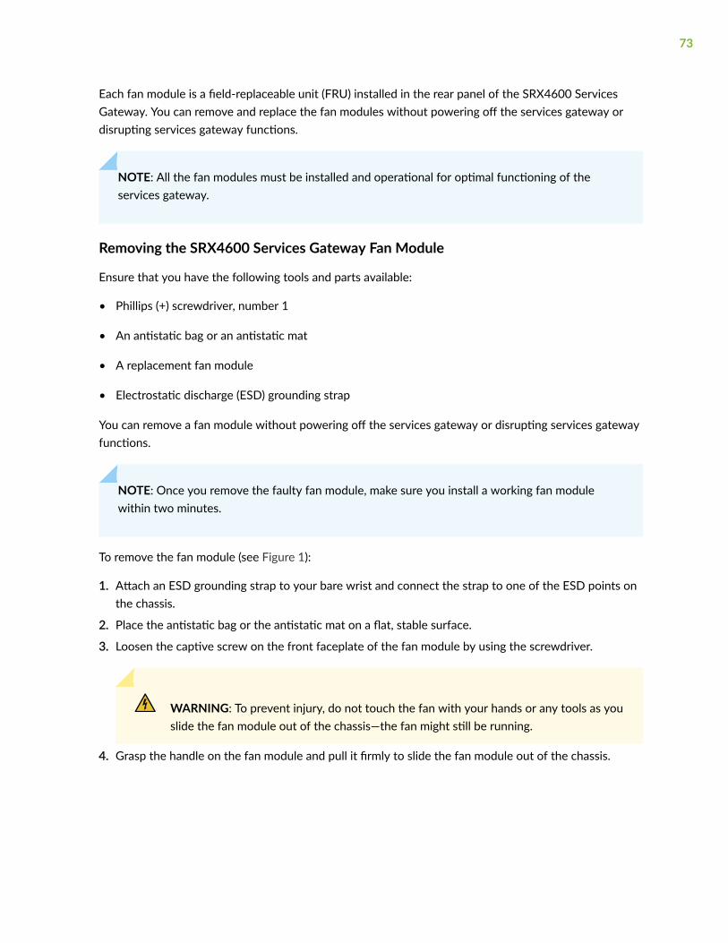
Each fan module is a field-replaceable unit (FRU) installed in the rear panel of the SRX4600 ServicesGateway. You can remove and replace the fan modules without powering off the services gateway ordisrupting services gateway functions.
NOTE: All the fan modules must be installed and operational for optimal functioning of theservices gateway.
Removing the SRX4600 Services Gateway Fan Module
Ensure that you have the following tools and parts available:
• Phillips (+) screwdriver, number 1
• An antistatic bag or an antistatic mat
• A replacement fan module
• Electrostatic discharge (ESD) grounding strap
You can remove a fan module without powering off the services gateway or disrupting services gatewayfunctions.
NOTE: Once you remove the faulty fan module, make sure you install a working fan modulewithin two minutes.
To remove the fan module (see Figure 1):
1. Attach an ESD grounding strap to your bare wrist and connect the strap to one of the ESD points onthe chassis.
2. Place the antistatic bag or the antistatic mat on a flat, stable surface.
3. Loosen the captive screw on the front faceplate of the fan module by using the screwdriver.
WARNING: To prevent injury, do not touch the fan with your hands or any tools as youslide the fan module out of the chassis—the fan might still be running.
4. Grasp the handle on the fan module and pull it firmly to slide the fan module out of the chassis.
73
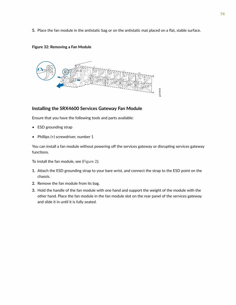
5. Place the fan module in the antistatic bag or on the antistatic mat placed on a flat, stable surface.
Figure 32: Removing a Fan Module
Installing the SRX4600 Services Gateway Fan Module
Ensure that you have the following tools and parts available:
• ESD grounding strap
• Phillips (+) screwdriver, number 1
You can install a fan module without powering off the services gateway or disrupting services gatewayfunctions.
To install the fan module, see (Figure 2):
1. Attach the ESD grounding strap to your bare wrist, and connect the strap to the ESD point on thechassis.
2. Remove the fan module from its bag.
3. Hold the handle of the fan module with one hand and support the weight of the module with theother hand. Place the fan module in the fan module slot on the rear panel of the services gatewayand slide it in until it is fully seated.
74
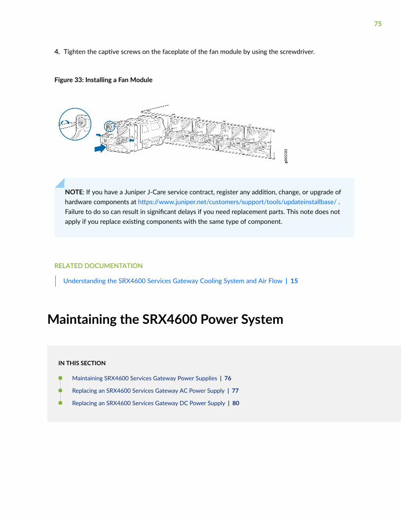
4. Tighten the captive screws on the faceplate of the fan module by using the screwdriver.
Figure 33: Installing a Fan Module
NOTE: If you have a Juniper J-Care service contract, register any addition, change, or upgrade ofhardware components at https://www.juniper.net/customers/support/tools/updateinstallbase/ .Failure to do so can result in significant delays if you need replacement parts. This note does notapply if you replace existing components with the same type of component.
RELATED DOCUMENTATION
Understanding the SRX4600 Services Gateway Cooling System and Air Flow | 15
Maintaining the SRX4600 Power System
IN THIS SECTION
Maintaining SRX4600 Services Gateway Power Supplies | 76
Replacing an SRX4600 Services Gateway AC Power Supply | 77
Replacing an SRX4600 Services Gateway DC Power Supply | 80
75

Maintaining SRX4600 Services Gateway Power Supplies
IN THIS SECTION
Purpose | 76
Action | 76
Purpose
For optimum services gateway performance, verify the condition of the power supplies.
Action
On a regular basis:
• To check the status of the power supplies, issue the show chassis environment pem command. The outputshown below is an example.
user@host> show chassis environment pemPEM 0 status: State Online Airflow Front to Back Temperature OK 45 degrees C / 113 degrees F Temperature OK 39 degrees C / 102 degrees F Temperature OK 28 degrees C / 82 degrees F Firmware version 04.10 Fan 0 9232 RPM DC Output Voltage(V) Current(A) Power(W) Load(%) 12.00 16 192 6PEM 1 status: State Online Airflow Front to Back Temperature OK 42 degrees C / 107 degrees F Temperature OK 35 degrees C / 95 degrees F Temperature OK 26 degrees C / 78 degrees F Firmware version 04.10 Fan 0 8896 RPM
76
DC Output Voltage(V) Current(A) Power(W) Load(%) 12.00 18 216 7
• Make sure that the power and grounding cables are arranged so that they do not obstruct access toother services gateway components.
• Routinely check the status LEDs on the power supply faceplates to determine whether the powersupplies are functioning normally. Each power supply faceplate displays a single LED to indicate thestatus of the power supply.
• Check the alarm LEDs on the front panel of the device. Power supply failure or removal triggers analarm that causes one or both of the LEDs to light. You can display the associated error messages byissuing the following command:
user@host> show chassis alarms
• Periodically inspect the site to ensure that the grounding and power cables connected to the deviceare securely in place and that there is no moisture accumulating near the device.
Replacing an SRX4600 Services Gateway AC Power Supply
IN THIS SECTION
Removing the SRX4600 Services Gateway AC Power Supply | 78
Installing the SRX4600 Services Gateway AC Power Supply | 79
Each power supply is a field-replaceable unit (FRU) installed in the rear panel of the SRX4600 ServicesGateway. You can remove and replace a power supply without powering off the services gateway ordisrupting services gateway functions.
NOTE: All the power supplies must be installed and operational for optimal functioning of theservices gateway.
77

Removing the SRX4600 Services Gateway AC Power Supply
Ensure that you have the following tools and parts available:
• Electrostatic discharge (ESD) grounding strap
• An antistatic bag or an antistatic mat
• Phillips (+) screwdriver, number 1
• A cover panel for the power supply slot
You can remove an AC power supply without powering off the services gateway or disrupting servicesgateway functions.
NOTE: Before you remove a power supply from the services gateway, ensure that you havetaken the necessary precautions to prevent ESD damage (see Prevention of ElectrostaticDischarge Damage).
CAUTION: We recommend that you install either a replacement power supply or acover panel in the empty power supply slot to prevent chassis overheating and dustaccumulation.
NOTE: After powering off a power supply, wait at least 60 seconds before turning it back on.
To remove an AC power supply, see (Figure 1):
1. If the AC power source outlet has a power switch, set it to the off (O) position. Follow theinstructions for your site.
2. Attach an ESD grounding strap to your bare wrist and connect the strap to one of the ESD pointson the chassis.
3. Place the antistatic bag or the antistatic mat on a flat, stable surface.
4. Gently pull out the plug end of the power cord connected to the power source outlet.
5. Remove the power cord from the power supply faceplate by detaching the power cord retainer andgently pulling out the socket end of the power cord connected to the power supply faceplate.
6. Slide the release latch to the left to unseat the power supply from the chassis. See Figure 1.
7. Grasp the power supply handle and pull firmly to slide the power supply halfway out of the chassis.
8. Place one hand under the power supply to support it and slide it completely out of the chassis. Takecare not to touch power supply components, pins, leads, or solder connections.
78

9. Place the power supply in the antistatic bag or on the antistatic mat placed on a flat, stable surface.
10. If you are not replacing the power supply, install the cover panel over the slot.
Figure 34: Removing an AC Power Supply
Installing the SRX4600 Services Gateway AC Power Supply
Ensure that you have the following tools and parts available:
• ESD grounding strap
• Phillips (+) screwdriver, number 1
You can install an AC Power Supply without powering off the services gateway or disrupting servicesgateway functions.
NOTE: Before you install a power supply from the services gateway, ensure that you have takenthe necessary precautions to prevent ESD damage (see Prevention of Electrostatic DischargeDamage).
To install the AC power supply, see (Figure 2):
1. Attach the ESD grounding strap to your bare wrist, and connect the strap to the ESD point on thechassis.
2. Taking care not to touch power supply pins, leads, or solder connections, remove the power supplyfrom the bag.
3. Using both hands, place the power supply in the power supply slot on the rear panel of the servicesgateway and slide it in until it is fully seated and slide the release latch to the right.
4. Insert the socket end of the power cord into the faceplate of the power supply and attach the powercord retainer.
5. Insert the plug end of the power cord to the power source outlet.
79

6. On the AC power source outlet, set the power switch to on (I) position. Follow the instructions foryour site.
7. Observe the status LED on the power supply faceplate. If the power supply is correctly installed andfunctioning normally, the status LED glows green steadily.
Figure 35: Installing an AC Power Supply
NOTE: If you have a Juniper J-Care service contract, register any addition, change, or upgrade ofhardware components at https://www.juniper.net/customers/support/tools/updateinstallbase/ .Failure to do so can result in significant delays if you need replacement parts. This note does notapply if you replace existing components with the same type of component.
Replacing an SRX4600 Services Gateway DC Power Supply
IN THIS SECTION
Removing the SRX4600 Services Gateway DC Power Supply | 81
Installing the SRX4600 Services Gateway DC Power Supply | 83
Each power supply is a field-replaceable unit (FRU) installed in the rear panel of the SRX4600 ServicesGateway. You can remove and replace a power supply without powering off the services gateway ordisrupting services gateway functions.
80
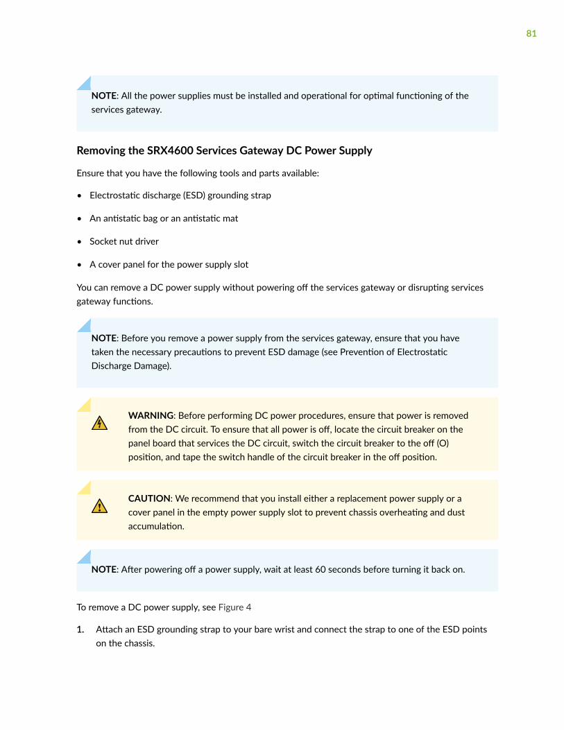
NOTE: All the power supplies must be installed and operational for optimal functioning of theservices gateway.
Removing the SRX4600 Services Gateway DC Power Supply
Ensure that you have the following tools and parts available:
• Electrostatic discharge (ESD) grounding strap
• An antistatic bag or an antistatic mat
• Socket nut driver
• A cover panel for the power supply slot
You can remove a DC power supply without powering off the services gateway or disrupting servicesgateway functions.
NOTE: Before you remove a power supply from the services gateway, ensure that you havetaken the necessary precautions to prevent ESD damage (see Prevention of ElectrostaticDischarge Damage).
WARNING: Before performing DC power procedures, ensure that power is removedfrom the DC circuit. To ensure that all power is off, locate the circuit breaker on thepanel board that services the DC circuit, switch the circuit breaker to the off (O)position, and tape the switch handle of the circuit breaker in the off position.
CAUTION: We recommend that you install either a replacement power supply or acover panel in the empty power supply slot to prevent chassis overheating and dustaccumulation.
NOTE: After powering off a power supply, wait at least 60 seconds before turning it back on.
To remove a DC power supply, see Figure 4
1. Attach an ESD grounding strap to your bare wrist and connect the strap to one of the ESD pointson the chassis.
81
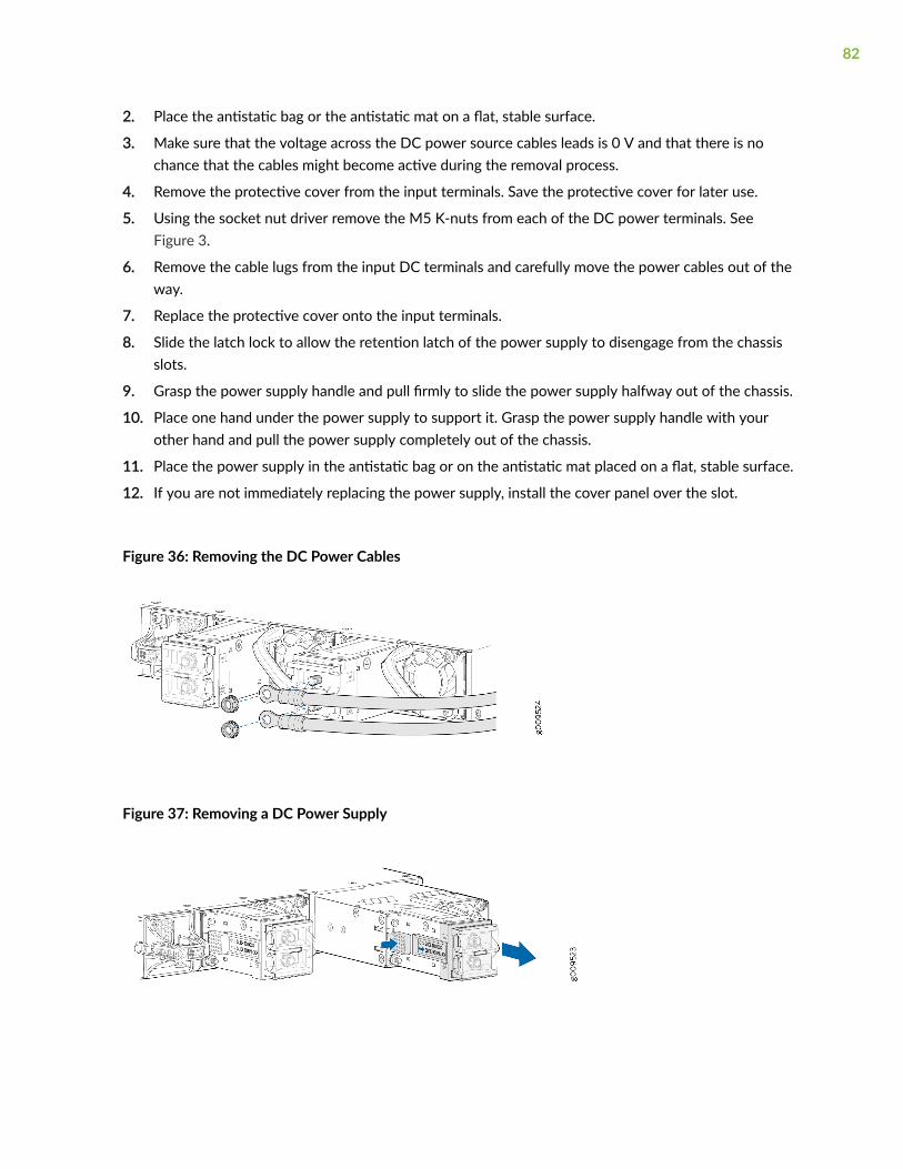
2. Place the antistatic bag or the antistatic mat on a flat, stable surface.
3. Make sure that the voltage across the DC power source cables leads is 0 V and that there is nochance that the cables might become active during the removal process.
4. Remove the protective cover from the input terminals. Save the protective cover for later use.
5. Using the socket nut driver remove the M5 K-nuts from each of the DC power terminals. SeeFigure 3.
6. Remove the cable lugs from the input DC terminals and carefully move the power cables out of theway.
7. Replace the protective cover onto the input terminals.
8. Slide the latch lock to allow the retention latch of the power supply to disengage from the chassisslots.
9. Grasp the power supply handle and pull firmly to slide the power supply halfway out of the chassis.
10. Place one hand under the power supply to support it. Grasp the power supply handle with yourother hand and pull the power supply completely out of the chassis.
11. Place the power supply in the antistatic bag or on the antistatic mat placed on a flat, stable surface.
12. If you are not immediately replacing the power supply, install the cover panel over the slot.
Figure 36: Removing the DC Power Cables
Figure 37: Removing a DC Power Supply
82

Installing the SRX4600 Services Gateway DC Power Supply
Ensure that you have the following tools and parts available:
• ESD grounding strap
• An antistatic bag or an antistatic mat
• Socket nut driver
You can install an DC Power Supply without powering off the services gateway or disrupting servicesgateway functions.
NOTE: Before you remove a power supply from the services gateway, ensure that you havetaken the necessary precautions to prevent ESD damage (see Prevention of ElectrostaticDischarge Damage).
WARNING: Before performing DC power procedures, ensure that power is removedfrom the DC circuit. To ensure that all power is off, locate the circuit breaker on thepanel board that services the DC circuit, switch the circuit breaker to the off (O)position, and tape the switch handle of the circuit breaker in the off position.
To install the DC power supply, see (Figure 5):
1. Attach the ESD grounding strap to your bare wrist, and connect the strap to the ESD point on thechassis.
2. Make sure that the voltage across the DC power source cables leads is 0 V and that there is nochance that the cables might become active during the removal process.
3. Using both hands, place the power supply in the power supply slot on the rear panel of the servicesgateway and slide it half way through.
4. Slide the latch lock to allow the retention latch of the power supply to move freely.
5. Silde the power supply completely into the chassis until it is fully seated and the retention latch isengaged into chassis slots.
6. Slide the latch lock to the right to prevent the retention latch from rotating. The power supply isnow locked into the chassis.
7. Remove the protective cover from the input terminals. Save the protective cover for later use.
8. Using the socket nut driver remove the M5 K-nuts from each of the DC power terminals.
9. Secure each power cable lug to the terminal with the M5 K-nuts (see Figure 6). Apply between 5 lb-in. (0.6 Nm) and 6 lb-in. (0.7 Nm) of torque to the nut. Do not overtighten the nut (use a socketnutdriver).
83

a. Secure the positive (+) DC source power cable lug to the RTN (return) terminal.
b. Secure the negative (–) DC source power cable lug to the –48V - 60V (input) terminal.
CAUTION: CAUTION: Ensure that each power cable lug seats flush against thesurface of the terminal block as you are tightening the socket nuts. Ensure that eachsocket nut is properly threaded into the terminal. Applying installation torque to thesocket nut when improperly threaded might result in damage to the terminal.
CAUTION: You must ensure that power connections maintain proper polarity. Thepower source cables might be labeled (+) and (–) to indicate their polarity. There isno standard color coding for DC power cables. The color coding used by theexternal DC power source at your site determines the color coding for the leads onthe power cables that attach to the terminal studs on each power supply.
10. Verify that the power cabling is correct, that the cables do not touch or block access to servicesgateway components, and that they do not drape where people could trip on them.
11. Replace the protective cover onto the input terminals.
12. Attach the power cable to the DC power source, and switch on the dedicated customer-site circuitbreaker. Follow the instructions for your site.
84
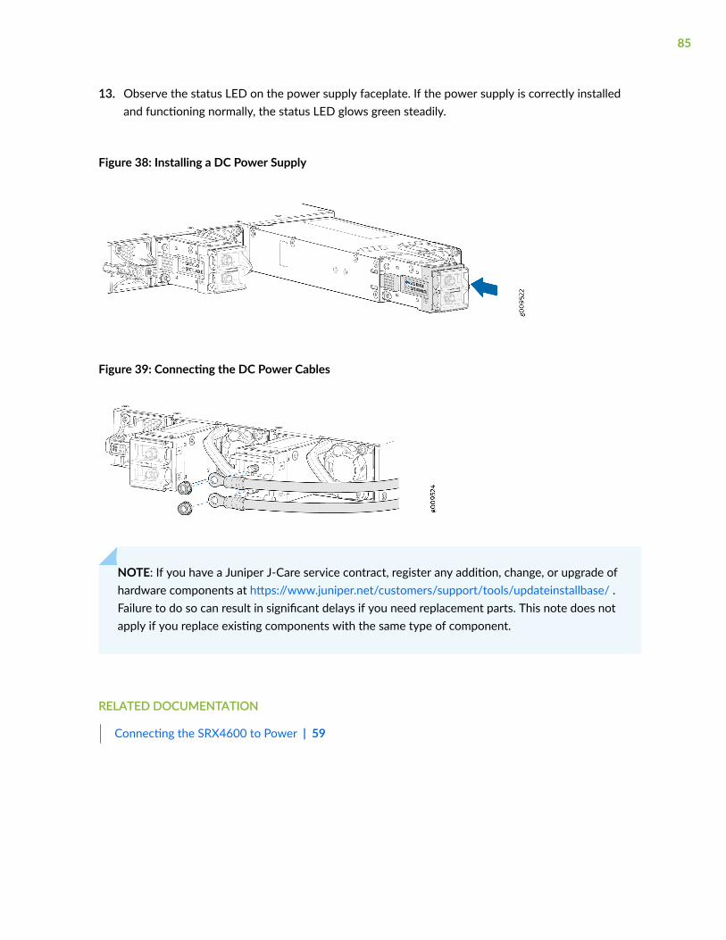
13. Observe the status LED on the power supply faceplate. If the power supply is correctly installedand functioning normally, the status LED glows green steadily.
Figure 38: Installing a DC Power Supply
Figure 39: Connecting the DC Power Cables
NOTE: If you have a Juniper J-Care service contract, register any addition, change, or upgrade ofhardware components at https://www.juniper.net/customers/support/tools/updateinstallbase/ .Failure to do so can result in significant delays if you need replacement parts. This note does notapply if you replace existing components with the same type of component.
RELATED DOCUMENTATION
Connecting the SRX4600 to Power | 59
85

Maintaining the SRX4600 SSD
IN THIS SECTION
Replacing an SRX4600 Services Gateway SSD | 86
Creating a Bootable USB Flash Drive to Install Junos OS on an SRX4600 Services Gateway | 88
Copying Files From or To an SRX4600 Services Gateway Using an USB Flash-Drive | 94
Replacing an SRX4600 Services Gateway SSD
IN THIS SECTION
Removing an SSD from an SRX4600 Services Gateway | 86
Installing an SSD in an SRX4600 Services Gateway | 87
This topic explains how to replace an Solid State-Drive (SSD) if RAID (Redundant Array of IndependentDisks) is not configured on your SRX4600 Services Gateway.
The two SSDs installed in the SRX4600 Services Gateway are field-replaceable unit (FRUs). You need topower off the SRX4600 Services Gateway to replace a SSD from the services gateway.
When you are replacing a faulty SSD with a new SSD that has no Junos OS installed on it or if you haveto reinstall the corrupted Junos OS image on the SSD, you should use a USB flash drive to install theJunos OS.
Removing an SSD from an SRX4600 Services Gateway
Ensure that you have the following equipment available:
• Electrostatic discharge (ESD) grounding strap
• An antistatic bag or an antistatic mat
• SSD to replace
86

You need to power off the SRX4600 Services Gateway to remove a SSD from the services gateway.
To remove an SSD, see (Figure 1):
1. Attach an ESD grounding strap to your bare wrist and connect the strap to one of the ESD points onthe chassis.
2. Place the antistatic bag or the antistatic mat on a flat, stable surface.
3. Place your thumb on the SSD handle and press the tab below the SSD handle with one finger tounlock the SSD from its slot.
4. Pull the SSD firmly to slide it out of its slot.
5. Place the SSD in the antistatic bag or on the antistatic mat placed on a flat, stable surface.
Figure 40: Removing an SSD
Installing an SSD in an SRX4600 Services Gateway
Ensure that you have the following equipment available:
• ESD grounding strap
You need to power off the SRX4600 Services Gateway to install a SSD into the services gateway.
To install an SSD, see (Figure 41 on page 88):
1. Attach an ESD grounding strap to your bare wrist and connect the strap to one of the ESD points onthe chassis.
2. Hold the SSD by its handle and slide it gently into its slot until the tab below the handle locks intothe SSD slot.
87
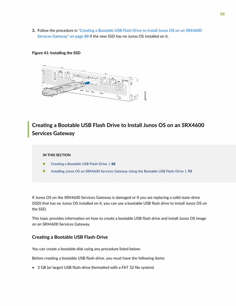
3. Follow the procedure in "Creating a Bootable USB Flash Drive to Install Junos OS on an SRX4600Services Gateway" on page 88 if the new SSD has no Junos OS installed on it.
Figure 41: Installing the SSD
Creating a Bootable USB Flash Drive to Install Junos OS on an SRX4600Services Gateway
IN THIS SECTION
Creating a Bootable USB Flash-Drive | 88
Installing Junos OS on SRX4600 Services Gateway Using the Bootable USB Flash-Drive | 93
If Junos OS on the SRX4600 Services Gateway is damaged or if you are replacing a solid state-drive(SSD) that has no Junos OS installed on it, you can use a bootable USB flash drive to install Junos OS onthe SSD.
This topic provides information on how to create a bootable USB flash drive and install Junos OS imageon an SRX4600 Services Gateway.
Creating a Bootable USB Flash-Drive
You can create a bootable disk using any procedure listed below:
Before creating a bootable USB flash-drive, you must have the following items:
• 3 GB (or larger) USB flash-drive (formatted with a FAT 32 file system)
88
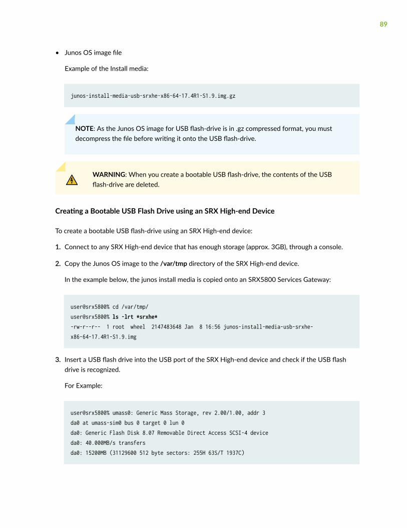
• Junos OS image file
Example of the Install media:
junos-install-media-usb-srxhe-x86-64-17.4R1-S1.9.img.gz
NOTE: As the Junos OS image for USB flash-drive is in .gz compressed format, you mustdecompress the file before writing it onto the USB flash-drive.
WARNING: When you create a bootable USB flash-drive, the contents of the USBflash-drive are deleted.
Creating a Bootable USB Flash Drive using an SRX High-end Device
To create a bootable USB flash-drive using an SRX High-end device:
1. Connect to any SRX High-end device that has enough storage (approx. 3GB), through a console.
2. Copy the Junos OS image to the /var/tmp directory of the SRX High-end device.
In the example below, the junos install media is copied onto an SRX5800 Services Gateway:
user@srx5800% cd /var/tmp/user@srx5800% ls -lrt *srxhe*-rw-r--r-- 1 root wheel 2147483648 Jan 8 16:56 junos-install-media-usb-srxhe-x86-64-17.4R1-S1.9.img
3. Insert a USB flash drive into the USB port of the SRX High-end device and check if the USB flashdrive is recognized.
For Example:
user@srx5800% umass0: Generic Mass Storage, rev 2.00/1.00, addr 3da0 at umass-sim0 bus 0 target 0 lun 0da0: Generic Flash Disk 8.07 Removable Direct Access SCSI-4 deviceda0: 40.000MB/s transfersda0: 15200MB (31129600 512 byte sectors: 255H 63S/T 1937C)
89
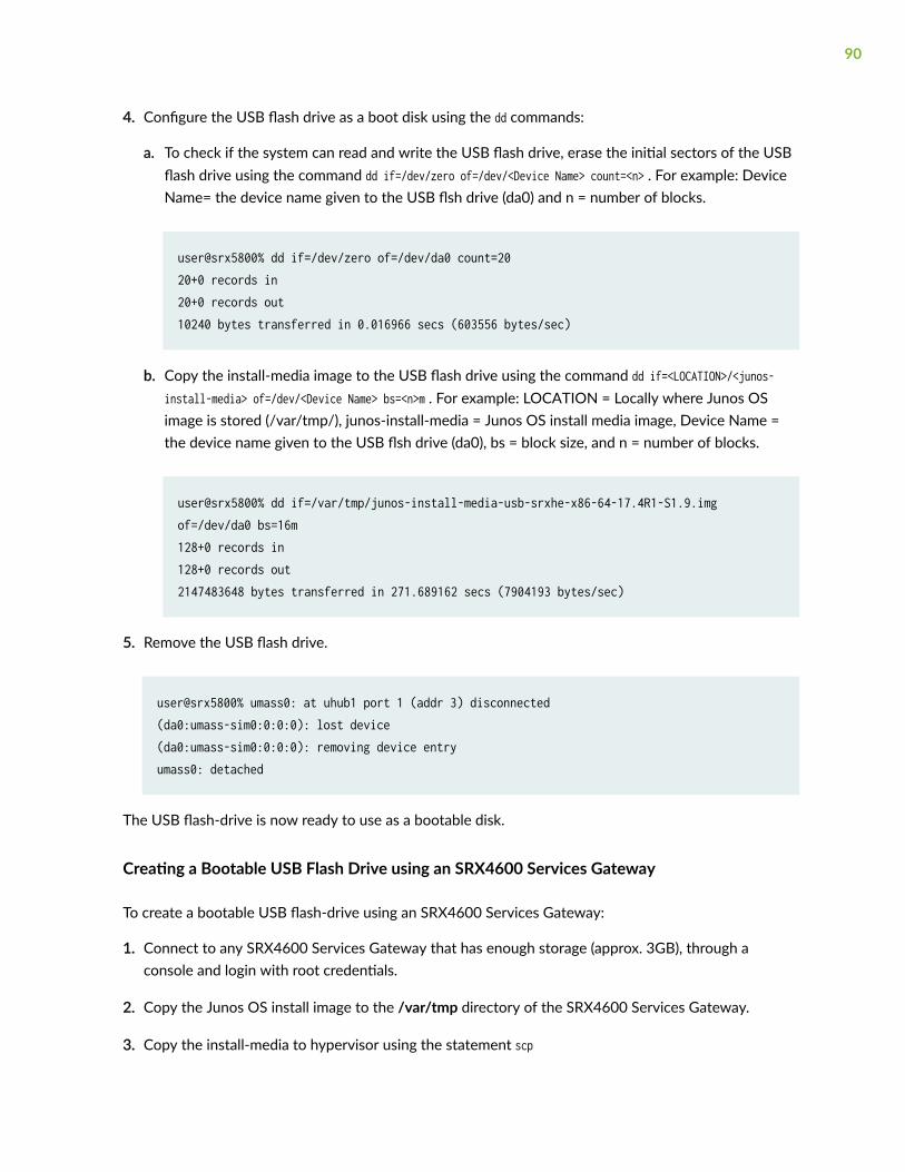
4. Configure the USB flash drive as a boot disk using the dd commands:
a. To check if the system can read and write the USB flash drive, erase the initial sectors of the USBflash drive using the command dd if=/dev/zero of=/dev/<Device Name> count=<n> . For example: DeviceName= the device name given to the USB flsh drive (da0) and n = number of blocks.
user@srx5800% dd if=/dev/zero of=/dev/da0 count=2020+0 records in20+0 records out10240 bytes transferred in 0.016966 secs (603556 bytes/sec)
b. Copy the install-media image to the USB flash drive using the command dd if=<LOCATION>/<junos-install-media> of=/dev/<Device Name> bs=<n>m . For example: LOCATION = Locally where Junos OSimage is stored (/var/tmp/), junos-install-media = Junos OS install media image, Device Name =the device name given to the USB flsh drive (da0), bs = block size, and n = number of blocks.
user@srx5800% dd if=/var/tmp/junos-install-media-usb-srxhe-x86-64-17.4R1-S1.9.imgof=/dev/da0 bs=16m128+0 records in128+0 records out2147483648 bytes transferred in 271.689162 secs (7904193 bytes/sec)
5. Remove the USB flash drive.
user@srx5800% umass0: at uhub1 port 1 (addr 3) disconnected(da0:umass-sim0:0:0:0): lost device(da0:umass-sim0:0:0:0): removing device entryumass0: detached
The USB flash-drive is now ready to use as a bootable disk.
Creating a Bootable USB Flash Drive using an SRX4600 Services Gateway
To create a bootable USB flash-drive using an SRX4600 Services Gateway:
1. Connect to any SRX4600 Services Gateway that has enough storage (approx. 3GB), through aconsole and login with root credentials.
2. Copy the Junos OS install image to the /var/tmp directory of the SRX4600 Services Gateway.
3. Copy the install-media to hypervisor using the statement scp
90
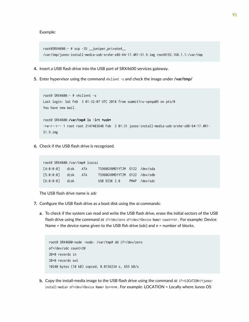
Example:
root@SRX4600:~ # scp -JU __juniper_private4__/var/tmp/junos-install-media-usb-srxhe-x86-64-17.4R1-S1.9.img [email protected]:/var/tmp
4. Insert a USB flash drive into the USB port of SRX4600 services gateway.
5. Enter hypervisor using the command vhclient -s and check the image under /var/tmp/
root@ SRX4600:~ # vhclient -sLast login: Sat Feb 3 01:32:07 UTC 2018 from summit1ru-vpnqa05 on pts/0You have new mail.
root@ SRX4600:/var/tmp# ls -lrt *usb*-rw-r--r-- 1 root root 2147483648 Feb 3 01:31 junos-install-media-usb-srxhe-x86-64-17.4R1-S1.9.img
6. Check if the USB flash drive is recognized.
root@ SRX4600:/var/tmp# lsscsi[4:0:0:0] disk ATA TS960GV8MD1YTJM O122 /dev/sda [5:0:0:0] disk ATA TS960GV8MD1YTJM O122 /dev/sdb [6:0:0:0] disk USB DISK 2.0 PMAP /dev/sdc
The USB flash drive name is sdc
7. Configure the USB flash drive as a boot disk using the dd commands:
a. To check if the system can read and write the USB flash drive, erase the initial sectors of the USBflash drive using the command dd if=/dev/zero of=/dev/<Device Name> count=<n> . For example: DeviceName = the device name given to the USB flsh drive (sdc) and n = number of blocks.
root@ SRX4600-node -node: /var/tmp# dd if=/dev/zeroof=/dev/sdc count=2020+0 records in20+0 records out10240 bytes (10 kB) copied, 0.0156234 s, 655 kB/s
b. Copy the install-media image to the USB flash drive using the command dd if=<LOCATION>/<junos-install-media> of=/dev/<Device Name> bs=<n>m . For example: LOCATION = Locally where Junos OS
91
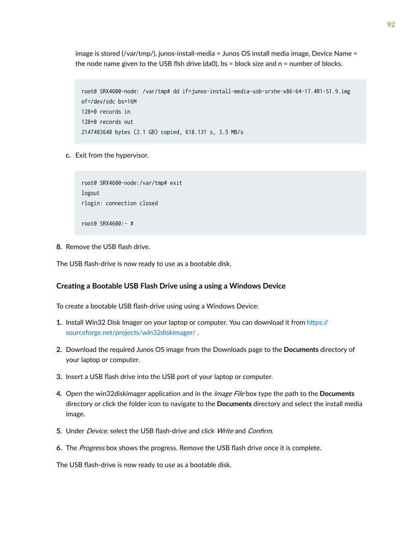
image is stored (/var/tmp/), junos-install-media = Junos OS install media image, Device Name =the node name given to the USB flsh drive (da0), bs = block size and n = number of blocks.
root@ SRX4600-node: /var/tmp# dd if=junos-install-media-usb-srxhe-x86-64-17.4R1-S1.9.imgof=/dev/sdc bs=16M128+0 records in128+0 records out2147483648 bytes (2.1 GB) copied, 618.131 s, 3.5 MB/s
c. Exit from the hypervisor.
root@ SRX4600-node:/var/tmp# exitlogoutrlogin: connection closed
root@ SRX4600:~ #
8. Remove the USB flash drive.
The USB flash-drive is now ready to use as a bootable disk.
Creating a Bootable USB Flash Drive using a using a Windows Device
To create a bootable USB flash-drive using using a Windows Device:
1. Install Win32 Disk Imager on your laptop or computer. You can download it from https://sourceforge.net/projects/win32diskimager/ .
2. Download the required Junos OS image from the Downloads page to the Documents directory ofyour laptop or computer.
3. Insert a USB flash drive into the USB port of your laptop or computer.
4. Open the win32diskimager application and in the Image File box type the path to the Documentsdirectory or click the folder icon to navigate to the Documents directory and select the install mediaimage.
5. Under Device, select the USB flash-drive and click Write and Confirm.
6. The Progress box shows the progress. Remove the USB flash drive once it is complete.
The USB flash-drive is now ready to use as a bootable disk.
92
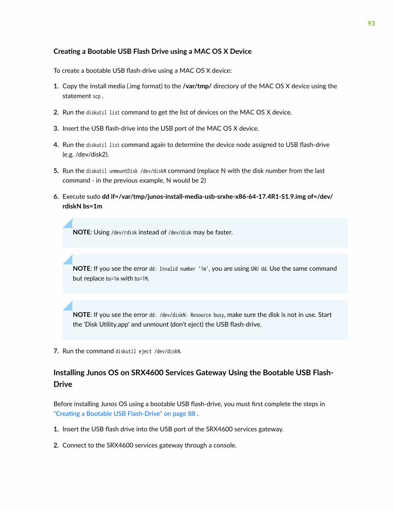
Creating a Bootable USB Flash Drive using a MAC OS X Device
To create a bootable USB flash-drive using a MAC OS X device:
1. Copy the install media (.img format) to the /var/tmp/ directory of the MAC OS X device using thestatement scp .
2. Run the diskutil list command to get the list of devices on the MAC OS X device.
3. Insert the USB flash-drive into the USB port of the MAC OS X device.
4. Run the diskutil list command again to determine the device node assigned to USB flash-drive(e.g. /dev/disk2).
5. Run the diskutil unmountDisk /dev/diskN command (replace N with the disk number from the lastcommand - in the previous example, N would be 2)
6. Execute sudo dd if=/var/tmp/junos-install-media-usb-srxhe-x86-64-17.4R1-S1.9.img of=/dev/rdiskN bs=1m
NOTE: Using /dev/rdisk instead of /dev/disk may be faster.
NOTE: If you see the error dd: Invalid number '1m', you are using GNU dd. Use the same commandbut replace bs=1m with bs=1M.
NOTE: If you see the error dd: /dev/diskN: Resource busy, make sure the disk is not in use. Startthe 'Disk Utility.app' and unmount (don't eject) the USB flash-drive.
7. Run the command diskutil eject /dev/diskN.
Installing Junos OS on SRX4600 Services Gateway Using the Bootable USB Flash-Drive
Before installing Junos OS using a bootable USB flash-drive, you must first complete the steps in"Creating a Bootable USB Flash-Drive" on page 88 .
1. Insert the USB flash drive into the USB port of the SRX4600 services gateway.
2. Connect to the SRX4600 services gateway through a console.
93

3. Power cycle (off/on) the SRX4600 services gateway and Press Esc for boot options.
4. Select Boot Manager and press Enter key.
5. From the Boot Option Menu, select USB flash drive and press Enter key.
6. In the GRUB Menu select “Install Juniper Linux with secure boot support” and press Enter key.
7. Once prompted “Remove the USB and press [Entre] key to Reboot...”, remove the USB flash drive andpress Enter key. SRX4600 services gateway will reboot with new software.
Copying Files From or To an SRX4600 Services Gateway Using an USBFlash-Drive
IN THIS SECTION
Copying Files From an SRX4600 Services Gateway Using an USB Flash-Drive | 94
Copying Files To an SRX4600 Services Gateway Using an USB Flash-Drive | 96
This topic explains how to copy files from or to an SRX4600 Services Gateway using an USB flash-drive.
Copying Files From an SRX4600 Services Gateway Using an USB Flash-Drive
This procedure explains how to copy files from an SRX4600 Services Gateway to an USB flash-drive.
1. Connect to SRX4600 Services Gateway through a console and login with root credentials.
2. Insert the USB flash drive (Formatted with FAT32 file system) into the SRX4600 USB port.
3. Enter into hypervisor by using the vhclient –s command.
root@srx4600:/var/tmp # vhclient -sLast login: Wed Nov 1 16:49:41 UTC 2017 from srx4600 on pts/0You have new mail.
root@srx4600-node:~#
94

4. Using the lsscsi command check if the USB flash-drive is being recognized.
root@srx4600-node:~# lsscsi[4:0:0:0] disk ATA TS960GV8MD1YTJM O122 /dev/sda [5:0:0:0] disk ATA TS960GV8MD1YTJM O122 /dev/sdb [6:0:0:0] disk UFD 3.0 Silicon-Power8G 1100 /dev/sdc
5. Mount the USB flash-drive.
root@srx4600-node:~# mkdir /var/tmp/usbroot@srx4600-node:~# mount /dev/sdc1 /var/tmp/usb
6. Go back to Junos prompt by using the exit command.
root@srx4600-node:~# exit root@srx4600:/var/tmp #
7. Use the command ls -lrt to list the files located at /var/tmp.
root@srx4600:/var/tmp # ls -lrt-rw-r--r-- 1 root wheel 1226057800 Nov 1 14:20 File1.txt
File1.txt is the file located in /var/tmp
8. Copy the required file to the USB flash-drive as shown in the example below.
In the example below File1.txt is copied to the USB flash-drive:
root@srx4600:/var/tmp # scp -JU __juniper_private4__File1.txt [email protected]:/var/tmp/usb/File1.txt 100% 1169MB 30.0MB/s 00:39root@srx4600:/var/tmp #
9. Go back to hypervisor.
root@srx4600:/var/tmp # vhclient -sLast login: Wed Nov 1 16:56:32 UTC 2017 from srx4600 on pts/0 You have new mail.
95
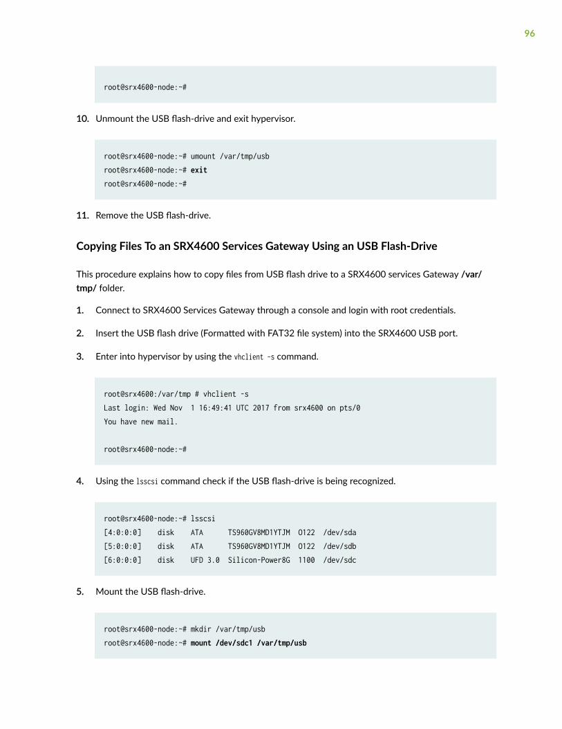
root@srx4600-node:~#
10. Unmount the USB flash-drive and exit hypervisor.
root@srx4600-node:~# umount /var/tmp/usbroot@srx4600-node:~# exitroot@srx4600-node:~#
11. Remove the USB flash-drive.
Copying Files To an SRX4600 Services Gateway Using an USB Flash-Drive
This procedure explains how to copy files from USB flash drive to a SRX4600 services Gateway /var/tmp/ folder.
1. Connect to SRX4600 Services Gateway through a console and login with root credentials.
2. Insert the USB flash drive (Formatted with FAT32 file system) into the SRX4600 USB port.
3. Enter into hypervisor by using the vhclient –s command.
root@srx4600:/var/tmp # vhclient -sLast login: Wed Nov 1 16:49:41 UTC 2017 from srx4600 on pts/0You have new mail.
root@srx4600-node:~#
4. Using the lsscsi command check if the USB flash-drive is being recognized.
root@srx4600-node:~# lsscsi[4:0:0:0] disk ATA TS960GV8MD1YTJM O122 /dev/sda [5:0:0:0] disk ATA TS960GV8MD1YTJM O122 /dev/sdb [6:0:0:0] disk UFD 3.0 Silicon-Power8G 1100 /dev/sdc
5. Mount the USB flash-drive.
root@srx4600-node:~# mkdir /var/tmp/usbroot@srx4600-node:~# mount /dev/sdc1 /var/tmp/usb
96
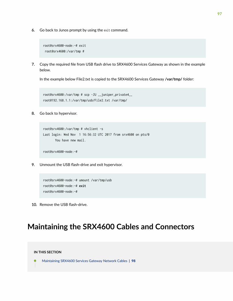
6. Go back to Junos prompt by using the exit command.
root@srx4600-node:~# exit root@srx4600:/var/tmp #
7. Copy the required file from USB flash drive to SRX4600 Services Gateway as shown in the examplebelow.
In the example below File2.txt is copied to the SRX4600 Services Gateway /var/tmp/ folder:
root@srx4600:/var/tmp # scp -JU [email protected]:/var/tmp/usb/File2.txt /var/tmp/
8. Go back to hypervisor.
root@srx4600:/var/tmp # vhclient -sLast login: Wed Nov 1 16:56:32 UTC 2017 from srx4600 on pts/0 You have new mail.
root@srx4600-node:~#
9. Unmount the USB flash-drive and exit hypervisor.
root@srx4600-node:~# umount /var/tmp/usbroot@srx4600-node:~# exitroot@srx4600-node:~#
10. Remove the USB flash-drive.
Maintaining the SRX4600 Cables and Connectors
IN THIS SECTION
Maintaining SRX4600 Services Gateway Network Cables | 98
97

How to Handle Fiber-Optic Cables | 99
Replacing Fibre Optic Cable on an SRX4600 Services Gateway | 99
Replacing an SFP+ Transceiver on an SRX4600 Services Gateway | 101
Replacing a QSFP28 Transceiver on an SRX4600 Services Gateway | 104
Maintaining SRX4600 Services Gateway Network Cables
IN THIS SECTION
Purpose | 98
Action | 98
Purpose
For optimum services gateway performance, verify the condition of the network cables.
Action
On a regular basis:
• Secure excess cable in tidy loops that do not obstruct access to the services gateway. Do not allowfastened loops of cable to dangle from the connector, because this stresses the cable at the fasteningpoint. Putting fasteners on the loops helps maintain their shape.
• Keep the cable connections clean and free of dust and other particles, which can cause drops in thereceived power level. Always inspect cables and clean them if necessary before connecting aninterface.
• Label both ends of the cables to identify them.
SEE ALSO
Routine Maintenance Procedures for the SRX4600 Services Gateway | 70
98
How to Handle Fiber-Optic Cables
Fiber-optic cables connect to optical transceivers that are installed in Juniper Networks devices.
To maintain fiber-optic cables:
• When you unplug a fiber-optic cable from a transceiver, place rubber safety caps over the transceiverand on the end of the cable.
• Anchor fiber-optic cables to prevent stress on the connectors. When attaching a fiber-optic cable toa transceiver, be sure to secure the fiber-optic cable so that it does not support its own weight as ithangs to the floor. Never let a fiber-optic cable hang free from the connector.
• Avoid bending fiber-optic cables beyond their minimum bend radius. Bending fiber-optic cables intoarcs smaller than a few inches in diameter can damage the cables and cause problems that aredifficult to diagnose.
• Frequent plugging and unplugging of fiber-optic cables in and out of optical instruments can damagethe instruments, which are expensive to repair. Attach a short fiber extension to the opticalequipment. Any wear and tear due to frequent plugging and unplugging is then absorbed by theshort fiber extension, which is easier and less expensive to replace than the instruments.
• Keep fiber-optic cable connections clean. Microdeposits of oil and dust in the canal of the transceiveror cable connector can cause loss of light, reduction in signal power, and possibly intermittentproblems with the optical connection.
• To clean the transceiver canal, use an appropriate fiber-cleaning device such as RIFOCS FiberOptic Adaptor Cleaning Wands (part number 946). Follow the instructions in the cleaning kit youuse.
• After cleaning the transceiver, make sure that the connector tip of the fiber-optic cable is clean.Use only an approved alcohol-free fiber-optic cable cleaning kit such as the Opptex Cletop-S®Fiber Cleaner. Follow the instructions in the cleaning kit you use.
Replacing Fibre Optic Cable on an SRX4600 Services Gateway
IN THIS SECTION
Disconnect a Fiber-Optic Cable | 100
Connect a Fiber-Optic Cable | 100
99

Disconnect a Fiber-Optic Cable
Before you disconnect a fiber-optic cable from an optical transceiver, ensure that you have taken thenecessary precautions for safe handling of lasers. See Laser and LED Safety Guidelines and Warnings.
Ensure that you have the following parts and tools available:
• A rubber safety cap to cover the transceiver
• A rubber safety cap to cover the fiber-optic cable connector
Juniper Networks devices have optical transceivers to which you can connect fiber-optic cables.
To disconnect a fiber-optic cable from an optical transceiver installed in the device:
1. Disable the port in which the transceiver is installed by issuing the following command:
[edit interfaces]user@device# set interface-name disable
LASER WARNING: Do not look directly into a fiber-optic transceiver or into the ends offiber-optic cables. Fiber-optic transceivers and fiber-optic cables connected to transceiversemit laser light that can damage your eyes.
2. Carefully unplug the fiber-optic cable connector from the transceiver.
3. Cover the transceiver with a rubber safety cap.
LASER WARNING: Do not leave a fiber-optic transceiver uncovered except when insertingor removing a cable. The rubber safety cap keeps the port clean and prevents accidentalexposure to laser light.
4. Cover the fiber-optic cable connector with the rubber safety cap.
Connect a Fiber-Optic Cable
Before you connect a fiber-optic cable to an optical transceiver installed in a device, ensure that youhave taken the necessary precautions for safe handling of lasers (see Laser and LED Safety Guidelinesand Warnings).
To connect a fiber-optic cable to an optical transceiver installed in a device:
100
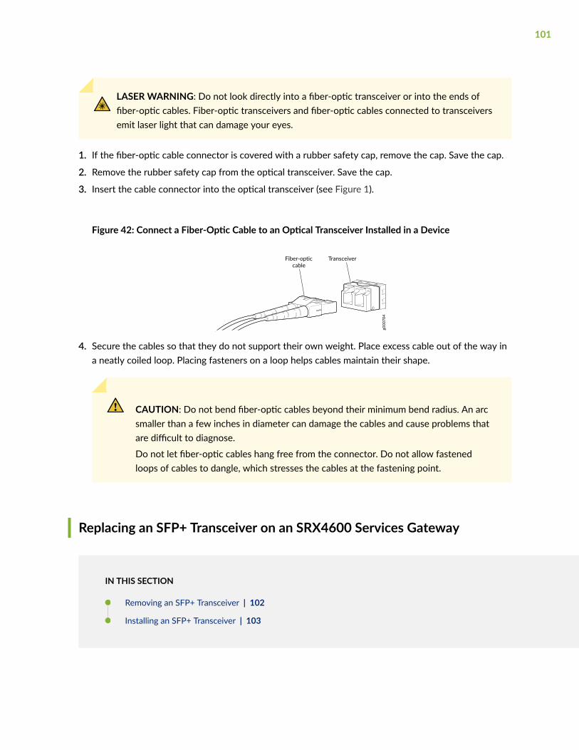
LASER WARNING: Do not look directly into a fiber-optic transceiver or into the ends offiber-optic cables. Fiber-optic transceivers and fiber-optic cables connected to transceiversemit laser light that can damage your eyes.
1. If the fiber-optic cable connector is covered with a rubber safety cap, remove the cap. Save the cap.
2. Remove the rubber safety cap from the optical transceiver. Save the cap.
3. Insert the cable connector into the optical transceiver (see Figure 1).
Figure 42: Connect a Fiber-Optic Cable to an Optical Transceiver Installed in a Device
g000
704
TransceiverFiber-opticcable
4. Secure the cables so that they do not support their own weight. Place excess cable out of the way ina neatly coiled loop. Placing fasteners on a loop helps cables maintain their shape.
CAUTION: Do not bend fiber-optic cables beyond their minimum bend radius. An arcsmaller than a few inches in diameter can damage the cables and cause problems thatare difficult to diagnose.
Do not let fiber-optic cables hang free from the connector. Do not allow fastenedloops of cables to dangle, which stresses the cables at the fastening point.
Replacing an SFP+ Transceiver on an SRX4600 Services Gateway
IN THIS SECTION
Removing an SFP+ Transceiver | 102
Installing an SFP+ Transceiver | 103
101

Small form-factor pluggable plus transceivers (SFP+) are enhanced SFP transceivers that providessupport for data rates of up to 10 Gbps for fiber-optic or copper interfaces. SFP+ transceivers are hot-removable and hot-insertable field-replaceable units (FRUs): You can remove and replace them withoutpowering off the device or disrupting device functions.
Figure 43: Small Form-Factor Pluggable (SFP) Transceiver
Removing an SFP+ Transceiver
To remove an SFP+ transceiver:
1. Have ready a replacement transceiver or a transceiver slot plug, an antistatic mat, and a rubber safetycap for the transceiver.
2. Attach an ESD grounding strap to your bare wrist, and connect the other end of the strap to an ESDgrounding point.
3. Label the cables connected to the transceiver so that you can reconnect them correctly later.
4. Remove the cable connector from the transceiver. Immediately cover the transceiver and the end ofthe cable with a rubber safety cap.
LASER WARNING: Do not look directly into a fiber-optic transceiver or into the ends offiber-optic cables. Fiber-optic transceivers and fiber-optic cables connected to atransceiver emit laser light that can damage your eyes.
5. Pull the ejector handle out from the transceiver to unlock the transceiver.
CAUTION: Make sure that you open the ejector handle completely until you hear itclick. This prevents damage to the transceiver.
Use needlenose pliers to pull the ejector handle out from the transceiver.
102

6. Grasp the transceiver ejector handle, and pull the transceiver approximately 0.5 in. (1.3 cm) out ofthe interface port.
7. Using your fingers, grasp the body of the transceiver, and pull it the rest of the way out of theinterface port.
8. Place a rubber safety cap over the transceiver.
9. Place the removed transceiver on an antistatic mat or in an electrostatic bag.
CAUTION: After removing a transceiver from the chassis, wait at least 30 secondsbefore reinserting it or inserting a transceiver into a different slot.
SEE ALSO
No Link Title
Installing an SFP+ Transceiver
To install an SFP+ transceiver:
1. Attach an ESD grounding strap to your bare wrist, and connect the other end of the strap to an ESDgrounding point.
2. Take each transceiver to be installed out of its electrostatic bag, and identify the slot on thecomponent where it will be installed.
3. Verify that each transceiver is covered by a rubber safety cap. If it is not, cover the transceiver with asafety cap.
4. Carefully align the transceiver with the slots in the component. The connectors should face thecomponent.
5. Slide the transceiver until the connector is seated in the component slot. If you are unable to fullyinsert the transceiver, make sure the connector is facing the right way.
6. Close the ejector handle of the transceiver.
7. Remove the rubber safety cap from the transceiver and the end of the cable. Insert the cable into thetransceiver.
LASER WARNING: Do not look directly into a fiber-optic transceiver or into the ends offiber-optic cables. Fiber-optic transceivers and fiber-optic cables connected to atransceiver emit laser light that can damage your eyes.
103

SEE ALSO
No Link Title
Replacing a QSFP28 Transceiver on an SRX4600 Services Gateway
IN THIS SECTION
Remove a QSFP28 Transceiver | 104
Install a QSFP28 Transceiver | 106
28-Gbps quad small form-factor pluggable (QSFP28) transceivers are hot-removable and hot-insertablefield-replaceable units (FRUs): You can remove and replace them without powering off the device ordisrupting device functions.
Remove a QSFP28 Transceiver
Before you remove a transceiver from a device, ensure that you have taken the necessary precautionsfor safe handling of lasers (see Laser and LED Safety Guidelines and Warnings).
Ensure that you have the following parts and tools available:
• An antistatic bag or an antistatic mat
• Rubber safety caps to cover the transceiver and fiber-optic cable connector
• A dust cover to cover the port or a replacement transceiver
The transceivers for Juniper Networks devices are hot-removable and hot-insertable field-replaceableunits (FRUs). You can remove and replace them without powering off the device or disrupting the devicefunctions.
NOTE: After you insert a transceiver or after you change the media-type configuration, wait for6 seconds for the interface to display operational commands.
104

NOTE: We recommend that you use only optical transceivers and optical connectors purchasedfrom Juniper Networks with your Juniper Networks device.
To remove a QSFP28 transceiver (see Figure 3):
1. Place an antistatic bag or antistatic mat on a flat, stable surface to receive the QSFP28 transceiver.Have a rubber safety cap ready for the QSFP28 transceiver and the cable.
2. Wrap and fasten one end of an ESD wrist strap around your bare wrist, and connect the other end ofthe strap to the ESD point on the switch.
3. Label the cable connected to the QSFP28 transceiver so that you can later reconnect it to the correctQSFP28 transceiver.
4. Disconnect the cable from the transceiver. Immediately cover the transceiver and the end of thecable with a rubber safety cap.
CAUTION: Do not leave a fiber-optic transceiver uncovered except when inserting orremoving a cable. The safety cap keeps the port clean and prevents accidentalexposure to laser light.
5. If there is a cable management system, arrange the cable in the cable management system to preventit from dislodging or developing stress points. Secure the cable so that it does not support its ownweight as it hangs to the floor. Place excess cable out of the way in a neatly coiled loop in the cablemanagement system. Placing fasteners on the loop helps to maintain its shape.
CAUTION: Do not bend the fiber-optic cable beyond its minimum bend radius. An arcsmaller than a few inches in diameter can damage the cable and cause problems thatare difficult to diagnose.
Figure 44: Remove a QSFP28 Transceiver
105

6. Pull the ejector tab straight back. The locking pins on the transceiver automatically release thetransceiver.
7. Place the transceiver on the antistatic mat or in the antistatic bag.
8. Place the dust cover over the empty port or install the replacement transceiver.
Install a QSFP28 Transceiver
Before you install a transceiver in a device, ensure that you have taken the necessary precautions forsafe handling of lasers (see Laser and LED Safety Guidelines and Warnings).
Ensure that you have a rubber safety cap available to cover the transceiver.
The transceivers for Juniper Networks devices are hot-removable and hot-insertable field-replaceableunits (FRUs): You can remove and replace them without powering off the device or disrupting the devicefunctions.
NOTE: After you insert a transceiver or after you change the media-type configuration, wait for6 seconds for the interface to display operational commands.
NOTE: We recommend that you use only optical transceivers and optical connectors purchasedfrom Juniper Networks with your Juniper Networks device.
CAUTION: If you face a problem running a Juniper Networks device that uses a third-party optic or cable, the Juniper Networks Technical Assistance Center (JTAC) can helpyou diagnose the source of the problem. Your JTAC engineer might recommend thatyou check the third-party optic or cable and potentially replace it with an equivalentJuniper Networks optic or cable that is qualified for the device.
To install a QSFP28 transceiver (see Figure 4):
1. Wrap and fasten one end of the ESD wrist strap around your bare wrist, and connect the other endof the strap to the ESD point on the switch.
2. Verify that a rubber safety cap covers the QSFP28 transceiver.
106

3. Orient the transceiver in front of the port so that the QSFP28 connector faces the appropriatedirection.
Figure 45: Install a QSFP28 Transceiver
4. Slide the transceiver into the slot until the locking pins lock in place. If there is resistance, remove thetransceiver and flip it so that the connector faces the other direction.
5. Remove the rubber safety cap from the transceiver and the end of the cable, and insert the cable intothe transceiver.
LASER WARNING: Do not look directly into a fiber-optic transceiver or into the ends offiber-optic cables. Fiber-optic transceivers and fiber-optic cable connected to a transceiveremit laser light that can damage your eyes.
CAUTION: Do not leave a fiber-optic transceiver uncovered except when inserting orremoving cable. The safety cap keeps the port clean and prevents accidental exposureto laser light.
6. If there is a cable management system, arrange the cable in the cable management system to preventthe cable from dislodging or developing stress points. Secure the cable so that it does not support itsown weight as it hangs to the floor. Place excess cable out of the way in a neatly coiled loop in thecable management system. Placing fasteners on the loop helps to maintain its shape.
CAUTION: Do not let fiber-optic cable hang free from the connector. Do not allowfastened loops of cable to dangle, which stresses the cable at the fastening point.
107

CAUTION: Avoid bending fiber-optic cable beyond its minimum bend radius. An arcsmaller than a few inches in diameter can damage the cable and cause problems thatare difficult to diagnose.
108

5CHAPTER
Troubleshooting Hardware
Troubleshooting the SRX4600 | 110

Troubleshooting the SRX4600
IN THIS SECTION
SRX4600 Services Gateway Troubleshooting Resources | 110
Chassis Component Alarm Conditions on an SRX4600 Services Gateway | 110
Troubleshooting the SRX4600 Services Gateway Cooling System | 115
Troubleshooting the SRX4600 Services Gateway Power System | 117
Using the RESET Button on the SRX4600 Services Gateway | 119
SRX4600 Services Gateway Troubleshooting Resources
To troubleshoot a services gateway, use the Junos OS command-line interface (CLI) and LEDs on thechassis:
• LEDs—When the services gateway detects an alarm condition, the status LED on the front panelglows red.
• CLI—The CLI is the primary tool for controlling and troubleshooting hardware, Junos OS, andnetwork connectivity. Use the CLI to display more information about alarms. CLI commands displayinformation about network connectivity derived from the ping and traceroute utilities. Forinformation about using the CLI to troubleshoot Junos OS, see the appropriate Junos OSconfiguration guide.
• JTAC—If you need assistance during troubleshooting, you can contact the Juniper NetworksTechnical Assistance Center (JTAC) by using the Web or by telephone. If you encounter softwareproblems, or problems with hardware components not discussed here, contact JTAC.
Chassis Component Alarm Conditions on an SRX4600 Services Gateway
You can monitor chassis alarms through the ALM LED. When the services gateway detects an alarmcondition, the ALM LED on the front panel glows and the level of severity can be either major (steadyred), or minor (yellow) or both major and minor (blinking red). To view a more detailed description of thealarm cause, issue the show chassis alarms and show system alarm commands.
110

Table 30 on page 111 describes alarms that can occur for the services gateway chassis component.
Table 30: Alarms for Services Gateway Chassis Components
Component Alarm Conditions Action Alarm Severity
Fan At least one of the fanshave failed.
• Check and adjust the roomtemperature, if possible.
• Check the air flow andensure that the airflowthrough the servicesgateway is unobstructed.
• Replace the failed fanmodule to avoid failure ofthe other fan modules.
• Open a support case usingthe Case Manager link athttps://www.juniper.net/support/ or call1-888-314-5822 (toll-freewithin the United Statesand Canada) or1-408-745-9500 (fromoutside the United States).
Steady red (major)
The services gatewaychassis temperature istoo warm.
• Check the roomtemperature.
• Check the air flow.
• Run all the Fans at fullspeed.
• Open a support case usingthe Case Manager link athttps://www.juniper.net/support/ or call1-888-314-5822 (toll-freewithin the United Statesand Canada) or1-408-745-9500 (fromoutside the United States).
Yellow (minor)/Red(major)
111
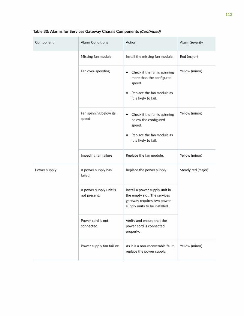
Table 30: Alarms for Services Gateway Chassis Components (Continued)
Component Alarm Conditions Action Alarm Severity
Missing fan module Install the missing fan module. Red (major)
Fan over-speeding • Check if the fan is spinningmore than the configuredspeed.
• Replace the fan module asit is likely to fail.
Yellow (minor)
Fan spinning below itsspeed
• Check if the fan is spinningbelow the configuredspeed.
• Replace the fan module asit is likely to fail.
Yellow (minor)
Impeding fan failure Replace the fan module. Yellow (minor)
Power supply A power supply hasfailed.
Replace the power supply. Steady red (major)
A power supply unit isnot present.
Install a power supply unit inthe empty slot. The servicesgateway requires two powersupply units to be installed.
Power cord is notconnected.
Verify and ensure that thepower cord is connectedproperly.
Power supply fan failure. As it is a non-recoverable fault,replace the power supply.
Yellow (minor)
112

Table 30: Alarms for Services Gateway Chassis Components (Continued)
Component Alarm Conditions Action Alarm Severity
Input failure to the powersupply
• Check the voltage of thepower source if it is in theoperating range.
• Open a support case usingthe Case Manager link athttps://www.juniper.net/support/ or call1-888-314-5822 (toll-freewithin the United Statesand Canada) or1-408-745-9500 (fromoutside the United States).
Red (major)
Power supply drawingmore current than itshould.
Open a support case using theCase Manager link at https://www.juniper.net/support/ orcall 1-888-314-5822 (toll-freewithin the United States andCanada) or 1-408-745-9500(from outside the UnitedStates).
Yellow (minor)
Unrecognized powersupply
Open a support case using theCase Manager link at https://www.juniper.net/support/ orcall 1-888-314-5822 (toll-freewithin the United States andCanada) or 1-408-745-9500(from outside the UnitedStates).
Red (major)
Power supply notpowered on.
Connect the power supply tothe power source.
Red (major)
113

Table 30: Alarms for Services Gateway Chassis Components (Continued)
Component Alarm Conditions Action Alarm Severity
Power supply internaldevices failure.
• Replace the power supply.
• Open a support case usingthe Case Manager link athttps://www.juniper.net/support/ or call1-888-314-5822 (toll-freewithin the United Statesand Canada) or1-408-745-9500 (fromoutside the United States).
Red (major)
Mix of AC and DC powersupplies installed.
Check if all the power suppliesinstalled are of the same type.
Yellow (minor)
SSD SSD detection failure • Check if there is powersupply to the SSD slot.
• Check if the SSDinitialization in BIOS isfailing.
• Replace the faulty SSD.
Yellow (minor)
SSD runtime read/writefault
• Check if there is any issuewith the SATA BUS.
• Check if the SSDinitialization is failing.
• Faulty SSD.
• Replace the faulty SSD.
Yellow (minor)
114

Table 30: Alarms for Services Gateway Chassis Components (Continued)
Component Alarm Conditions Action Alarm Severity
SSD File systemcorrupted
• Check if there is any issuewith the SSD subsystem.
• Was there any abruptpower removal to theservices gateway.
• Check if any non gracefulshutdown or reset of theservices gateway.
• Check for RAM relatedissues.
• Recover or re-image theSSD
Yellow (minor)
USB USB Device not detected • Check if there is any powersupply issue to the USBslot.
• Check for the port levelfailures.
• Check for USB link to portfrom PCH failures.
• Check if the USB is faulty,and replace the faulty USB.
Yellow (minor)
Troubleshooting the SRX4600 Services Gateway Cooling System
IN THIS SECTION
Problem | 116
115

Solution | 116
Problem
Description
A single fan module or fan modules are not functioning normally.
Solution
Follow these guidelines to troubleshoot the fan modules:
• Check the LEDs on the fan module and alarm LEDs on the front panel of the services gateway.
• If the alarm LED on the front panel of the services gateway is lit, use the following CLI command toget information about the source of an alarm condition:user@host> show chassis alarms.
If the CLI output lists only one fan failure, and the other fans are functioning normally, the fan is mostlikely faulty and you must replace the fan tray.
• Place your hand near the near the fan modules to determine whether the fans are pushing air out ofthe chassis.
• If the fan tray is removed, a minor alarm or a major alarm is raised.
• The following conditions automatically cause the fans to run at full speed and also trigger theindicated alarm:
• A fan fails (major alarm).
• The services gateway temperature exceeds the “temperature warm” threshold (minor alarm).
• The temperature of the services gateway exceeds the maximum (“temperature hot”) threshold(major alarm and automatic shutdown of the power supplies).
116

Troubleshooting the SRX4600 Services Gateway Power System
IN THIS SECTION
Problem | 117
Solution | 117
Problem
Description
The power system is not functioning normally.
Solution
• Check the LEDs on each power supply faceplate. If an AC or a DC power supply is correctly installedand functioning normally, then the LEDs glow steadily.
For more information about power supply LEDs, see "SRX4600 Power System" on page 19.
• Use the CLI show chassis environment pem command to check the status of installed powersupplies. The output shown below is an example.
user@host> show chassis environment pemPEM 0 status: State Online Airflow Front to Back Temperature OK 45 degrees C / 113 degrees F Temperature OK 39 degrees C / 102 degrees F Temperature OK 28 degrees C / 82 degrees F Firmware version 04.10 Fan 0 9232 RPM DC Output Voltage(V) Current(A) Power(W) Load(%) 12.00 16 192 6PEM 1 status: State Online Airflow Front to Back
117
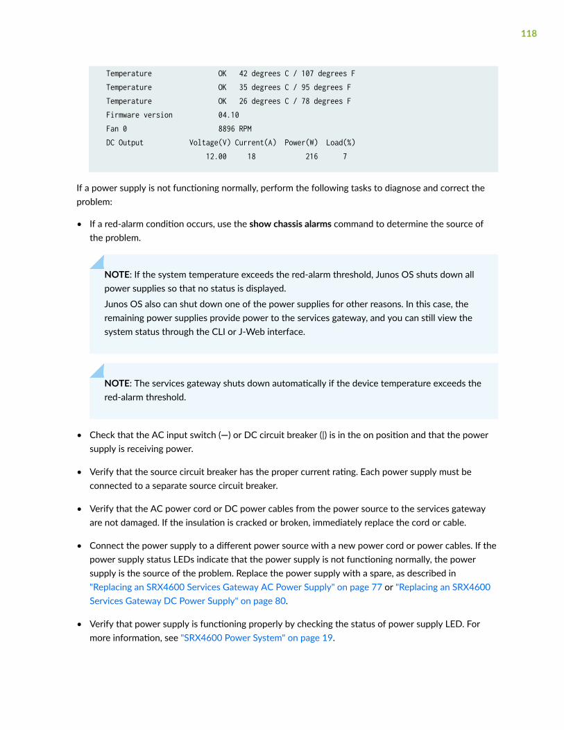
Temperature OK 42 degrees C / 107 degrees F Temperature OK 35 degrees C / 95 degrees F Temperature OK 26 degrees C / 78 degrees F Firmware version 04.10 Fan 0 8896 RPM DC Output Voltage(V) Current(A) Power(W) Load(%) 12.00 18 216 7
If a power supply is not functioning normally, perform the following tasks to diagnose and correct theproblem:
• If a red-alarm condition occurs, use the show chassis alarms command to determine the source ofthe problem.
NOTE: If the system temperature exceeds the red-alarm threshold, Junos OS shuts down allpower supplies so that no status is displayed.
Junos OS also can shut down one of the power supplies for other reasons. In this case, theremaining power supplies provide power to the services gateway, and you can still view thesystem status through the CLI or J-Web interface.
NOTE: The services gateway shuts down automatically if the device temperature exceeds thered-alarm threshold.
• Check that the AC input switch (—) or DC circuit breaker (|) is in the on position and that the powersupply is receiving power.
• Verify that the source circuit breaker has the proper current rating. Each power supply must beconnected to a separate source circuit breaker.
• Verify that the AC power cord or DC power cables from the power source to the services gatewayare not damaged. If the insulation is cracked or broken, immediately replace the cord or cable.
• Connect the power supply to a different power source with a new power cord or power cables. If thepower supply status LEDs indicate that the power supply is not functioning normally, the powersupply is the source of the problem. Replace the power supply with a spare, as described in"Replacing an SRX4600 Services Gateway AC Power Supply" on page 77 or "Replacing an SRX4600Services Gateway DC Power Supply" on page 80.
• Verify that power supply is functioning properly by checking the status of power supply LED. Formore information, see "SRX4600 Power System" on page 19.
118

• If you cannot determine the cause of the problem or need additional assistance whiletroubleshooting a services gateway, open a support case using the Case Manager link at: https://www.juniper.net/support/ , or call 1-888-314-JTAC (within the United States) or 1-408-745-9500.
Using the RESET Button on the SRX4600 Services Gateway
To cold reboot the SRX4600 Services Gateway, press and hold the RESET button for less than 5seconds.
CAUTION: Do not press and hold the RESET button for more that 5 seconds.
RELATED DOCUMENTATION
Understanding the SRX4600 Services Gateway Chassis | 4
Understanding the SRX4600 Services Gateway Cooling System and Air Flow | 15
Routine Maintenance Procedures for the SRX4600 Services Gateway | 70
119

6CHAPTER
Contacting Customer Support andReturning the Chassis or Components
Returning the SRX4600 Chassis or Components | 121

Returning the SRX4600 Chassis or Components
IN THIS SECTION
Contacting Customer Support | 121
Return Procedure for the SRX4600 Services Gateway or Component to Juniper Networks | 122
Locating the Serial Number on the SRX4600 Services Gateway or Component | 123
Packing an SRX4600 Services Gateway or Component for Shipping | 127
Contacting Customer Support
Once you have located the serial numbers of the device or component, you can return the device orcomponent for repair or replacement. For this, you need to contact Juniper Networks TechnicalAssistance Center (JTAC).
You can contact JTAC 24 hours a day, 7 days a week, using any of the following methods:
• On the Web: Using the Service Request Manager link at https://support.juniper.net/support/
• By telephone:
• From the US and Canada: 1-888-314-JTAC
• From all other locations: 1-408-745-9500
NOTE: If contacting JTAC by telephone, enter your 12-digit service request numberfollowed by the pound (#) key if this is an existing case, or press the star (*) key to berouted to the next available support engineer.
When requesting support from JTAC by telephone, be prepared to provide the following information:
• Your existing service request number, if you have one
• Details of the failure or problem
• Type of activity being performed on the services gateway when the problem occurred
• Configuration data displayed by one or more show commands
121
• Your name, organization name, telephone number, fax number, and shipping address
The support representative validates your request and issues a Return Materials Authorization (RMA)number for return of the device or component.
Return Procedure for the SRX4600 Services Gateway or Component toJuniper Networks
If a problem cannot be resolved by the JTAC technician, a Return Materials Authorization (RMA) isissued. This number is used to track the returned material at the factory and to return repaired or newcomponents to the customer as needed.
NOTE: Do not return any component to Juniper Networks, Inc. unless you have first obtained anRMA number. Juniper Networks, Inc. reserves the right to refuse shipments that do not have anRMA. Refused shipments will be returned to the customer via collect freight.
For more information about return and repair policies, see the customer support Web page at https://www.juniper.net/support/guidelines.html .
To return a services gateway or component to Juniper Networks for repair or replacement:
1. Determine the part number and serial number of the services gateway or component.
2. Obtain a Return Materials Authorization (RMA) number from JTAC.
NOTE: Do not return the services gateway or any component to Juniper Networks unless youhave first obtained an RMA number. Juniper Networks reserves the right to refuse shipmentsthat do not have an RMA. Refused shipments are returned to the customer via collect freight.
3. Pack the services gateway or component for shipping.
For more information about return and repair policies, see the customer support webpage at https://www.juniper.net/support/guidelines.html .
For product problems or technical support issues, open a support case using the Case Manager link athttps://support.juniper.net/support/ or call 1-888-314-JTAC (within the United States) or1-408-745-9500 (outside the United States).
122

Locating the Serial Number on the SRX4600 Services Gateway orComponent
IN THIS SECTION
Listing the SRX4600 Services Gateway Component Details with the CLI | 123
Locating the SRX4600 Services Gateway Chassis Serial Number ID Label | 124
Locating the Serial Number ID Labels on SRX4600 Services Gateway Power Supplies | 124
Locating the Serial Number ID Labels on SRX4600 Services Gateway Fan Modules | 125
Locating the Serial Number ID Labels on SRX4600 Services Gateway SSDs | 126
If you are returning a services gateway or hardware component to Juniper Networks for repair orreplacement, you must locate the serial number of the services gateway or component. You mustprovide the serial number to the Juniper Networks Technical Assistance Center (JTAC) when you contactthem to obtain Return Materials Authorization (RMA).
If the services gateway is operational and you can access the CLI, you can list serial numbers for theservices gateway and for some components with a CLI command. If you do not have access to the CLI orif the serial number for the component does not appear in the command output, you can locate theserial number ID label on the physical device or component.
Listing the SRX4600 Services Gateway Component Details with the CLI
Before contacting Juniper Networks to request a Return Materials Authorization (RMA), you must findthe serial number on the SRX4600 Services Gateway or component. To list all the SRX4600 ServicesGateway components and their serial numbers, enter the following CLI command:
user@host> show chassis hardwareHardware inventory:Item Version Part number Serial number DescriptionChassis JN12642A8JCA SRX4600Routing Engine 0 BUILTIN BUILTIN Routing EnginePseudo CB 0 Mezz REV 11 711-066896 CAHR4936 Control Mezz BoardFPC 0 REV 08 711-065484 CAHM6659 SRX4600 SPM CPU PIC 0 BUILTIN BUILTIN 4x 10GE SFP+ HA
123
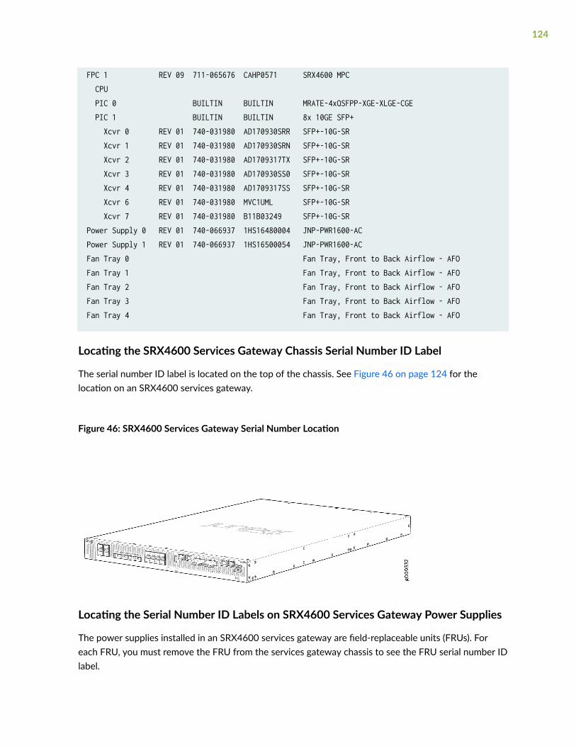
FPC 1 REV 09 711-065676 CAHP0571 SRX4600 MPC CPU PIC 0 BUILTIN BUILTIN MRATE-4xQSFPP-XGE-XLGE-CGE PIC 1 BUILTIN BUILTIN 8x 10GE SFP+ Xcvr 0 REV 01 740-031980 AD170930SRR SFP+-10G-SR Xcvr 1 REV 01 740-031980 AD170930SRN SFP+-10G-SR Xcvr 2 REV 01 740-031980 AD1709317TX SFP+-10G-SR Xcvr 3 REV 01 740-031980 AD170930SS0 SFP+-10G-SR Xcvr 4 REV 01 740-031980 AD1709317SS SFP+-10G-SR Xcvr 6 REV 01 740-031980 MVC1UML SFP+-10G-SR Xcvr 7 REV 01 740-031980 B11B03249 SFP+-10G-SRPower Supply 0 REV 01 740-066937 1HS16480004 JNP-PWR1600-ACPower Supply 1 REV 01 740-066937 1HS16500054 JNP-PWR1600-ACFan Tray 0 Fan Tray, Front to Back Airflow - AFOFan Tray 1 Fan Tray, Front to Back Airflow - AFOFan Tray 2 Fan Tray, Front to Back Airflow - AFOFan Tray 3 Fan Tray, Front to Back Airflow - AFOFan Tray 4 Fan Tray, Front to Back Airflow - AFO
Locating the SRX4600 Services Gateway Chassis Serial Number ID Label
The serial number ID label is located on the top of the chassis. See Figure 46 on page 124 for thelocation on an SRX4600 services gateway.
Figure 46: SRX4600 Services Gateway Serial Number Location
Locating the Serial Number ID Labels on SRX4600 Services Gateway Power Supplies
The power supplies installed in an SRX4600 services gateway are field-replaceable units (FRUs). Foreach FRU, you must remove the FRU from the services gateway chassis to see the FRU serial number IDlabel.
124

• AC power supply—The serial number ID label is on the top of the AC power supply. See Figure 47 onpage 125.
Figure 47: SRX4600 Services Gateway AC Power Supply Serial Number Location
• DC power supply—The serial number ID label is on the top of the DC power supply. See Figure 48 onpage 125.
Figure 48: SRX4600 Services Gateway DC Power Supply Serial Number Location
Locating the Serial Number ID Labels on SRX4600 Services Gateway Fan Modules
The five fan modules installed in an SRX4600 Services Gateway are field-replaceable units (FRUs). Foreach FRU, you must remove the FRU from the services gateway chassis to see the FRU serial number IDlabel.
125

The serial number ID label is on the top of the fan module. See Figure 49 on page 126.
Figure 49: SRX4600 Services Gateway Fan Module Serial Number Location
Locating the Serial Number ID Labels on SRX4600 Services Gateway SSDs
The two SSDs installed in the SRX4600 Services Gateway are field-replaceable unit (FRUs). For eachFRU, you must remove the FRU from the services gateway chassis to see the FRU serial number IDlabel.
The serial number ID label is on the top of the SSD. See Figure 50 on page 126.
Figure 50: SRX4600 Services Gateway SSD Serial Number Location
1— Serial number
126

Packing an SRX4600 Services Gateway or Component for Shipping
IN THIS SECTION
Packing the SRX4600 Services Gateway for Shipment | 127
Packing the SRX4600 Services Gateway Components for Shipment | 128
Before you pack an SRX4600 Services Gateway or component:
• Ensure that you have taken the necessary precautions to prevent electrostatic discharge (ESD)damage.
• Retrieve the original shipping carton and packing materials. Contact your JTAC representative if youdo not have these materials, to learn about approved packing materials. See "Contacting CustomerSupport" on page 121.
Ensure that you have the following parts and tools available:
• ESD grounding strap
• Antistatic bag, one for each component
• Phillips (+) screwdriver, number 1
Packing the SRX4600 Services Gateway for Shipment
To pack the services gateway for shipment:
1. Attach an electrostatic discharge (ESD) grounding strap to your bare wrist and connect the strap tothe ESD point on the chassis or to an outside ESD point if the device is disconnected from earthground. .
2. On the console or other management device connected to the services gateway, enter CLIoperational mode and issue the following command to shut down the services gateway software:
user@host> request system power-off
Wait until a message appears on the console confirming that the operating system has halted.
3. Shut down power to the services gateway.
4. Disconnect power from the services gateway.
5. Remove the cables that connect to all external devices.
6. If the services gateway is installed in a rack, have one person support the weight of the servicesgateway while another person unscrews and removes the mounting screws.
127

7. Place the services gateway in the shipping carton.
8. Cover the services gateway with an ESD bag, and place the packing foam on top of and around thedevice.
9. Replace the accessory box on top of the packing foam.
10. Securely tape the box closed.
11. Write the Return Materials Authorization (RMA) number on the exterior of the box to ensureproper tracking.
Packing the SRX4600 Services Gateway Components for Shipment
Follow these guidelines for packing and shipping individual components of the services gateway:
• When you return a component, make sure that it is adequately protected with packing materials andpacked so that the pieces are prevented from moving around inside the carton.
• Use the original shipping materials if they are available.
• Place the individual component in an electrostatic bag.
• Write the Return Materials Authorization (RMA) number on the exterior of the box to ensure propertracking.
CAUTION: Do not stack any of the services gateway components during packing.
128

7CHAPTER
Safety and Compliance Information
General Safety Guidelines and Warnings | 131
Definitions of Safety Warning Levels | 132
Restricted Access Area Warning | 134
Fire Safety Requirements | 135
Qualified Personnel Warning | 137
Warning Statement for Norway and Sweden | 137
Installation Instructions Warning | 138
Chassis and Component Lifting Guidelines | 138
Ramp Warning | 139
Rack-Mounting and Cabinet-Mounting Warnings | 139
Grounded Equipment Warning | 144
Laser and LED Safety Guidelines and Warnings | 144
Radiation from Open Port Apertures Warning | 147
Maintenance and Operational Safety Guidelines and Warnings | 148
General Electrical Safety Guidelines and Warnings | 154
Prevention of Electrostatic Discharge Damage | 156
AC Power Electrical Safety Guidelines | 157
AC Power Disconnection Warning | 158
DC Power Electrical Safety Guidelines | 159
DC Power Disconnection Warning | 166
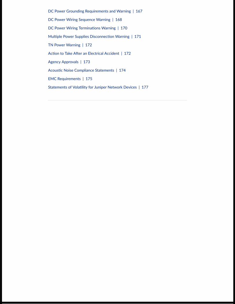
DC Power Grounding Requirements and Warning | 167
DC Power Wiring Sequence Warning | 168
DC Power Wiring Terminations Warning | 170
Multiple Power Supplies Disconnection Warning | 171
TN Power Warning | 172
Action to Take After an Electrical Accident | 172
Agency Approvals | 173
Acoustic Noise Compliance Statements | 174
EMC Requirements | 175
Statements of Volatility for Juniper Network Devices | 177

General Safety Guidelines and Warnings
The following guidelines help ensure your safety and protect the device from damage. The list ofguidelines might not address all potentially hazardous situations in your working environment, so bealert and exercise good judgment at all times.
• Perform only the procedures explicitly described in the hardware documentation for this device.Make sure that only authorized service personnel perform other system services.
• Keep the area around the device clear and free from dust before, during, and after installation.
• Keep tools away from areas where people could trip over them while walking.
• Do not wear loose clothing or jewelry, such as rings, bracelets, or chains, which could become caughtin the device.
• Wear safety glasses if you are working under any conditions that could be hazardous to your eyes.
• Do not perform any actions that create a potential hazard to people or make the equipment unsafe.
• Never attempt to lift an object that is too heavy for one person to handle.
• Never install or manipulate wiring during electrical storms.
• Never install electrical jacks in wet locations unless the jacks are specifically designed for wetenvironments.
• Operate the device only when it is properly grounded.
• Follow the instructions in this guide to properly ground the device to earth.
• Replace fuses only with fuses of the same type and rating.
• Do not open or remove chassis covers or sheet-metal parts unless instructions are provided in thehardware documentation for this device. Such an action could cause severe electrical shock.
• Do not push or force any objects through any opening in the chassis frame. Such an action couldresult in electrical shock or fire.
• Avoid spilling liquid onto the chassis or onto any device component. Such an action could causeelectrical shock or damage the device.
• Avoid touching uninsulated electrical wires or terminals that have not been disconnected from theirpower source. Such an action could cause electrical shock.
131

• Some parts of the chassis, including AC and DC power supply surfaces, power supply unit handles,SFB card handles, and fan tray handles might become hot. The following label provides the warningof the hot surfaces on the chassis:
• Always ensure that all modules, power supplies, and cover panels are fully inserted and that theinstallation screws are fully tightened.
Definitions of Safety Warning Levels
The documentation uses the following levels of safety warnings (there are two Warning formats):
NOTE: You might find this information helpful in a particular situation, or you might overlook thisimportant information if it was not highlighted in a Note.
CAUTION: You need to observe the specified guidelines to prevent minor injury ordiscomfort to you or severe damage to the device.
Attention Veillez à respecter les consignes indiquées pour éviter toute incommodité oublessure légère, voire des dégâts graves pour l’appareil.
LASER WARNING: This symbol alerts you to the risk of personal injury from a laser.
Avertissement Ce symbole signale un risque de blessure provoquée par rayon laser.
WARNING: This symbol means danger. You are in a situation that could cause bodilyinjury. Before you work on any equipment, be aware of the hazards involved withelectrical circuitry and be familiar with standard practices for preventing accidents.
Waarschuwing Dit waarschuwingssymbool betekent gevaar. U verkeert in een situatiedie lichamelijk letsel kan veroorzaken. Voordat u aan enige apparatuur gaat werken,
132
dient u zich bewust te zijn van de bij elektrische schakelingen betrokken risico's en dientu op de hoogte te zijn van standaard maatregelen om ongelukken te voorkomen.
Varoitus Tämä varoitusmerkki merkitsee vaaraa. Olet tilanteessa, joka voi johtaaruumiinvammaan. Ennen kuin työskentelet minkään laitteiston parissa, ota selvääsähkökytkentöihin liittyvistä vaaroista ja tavanomaisista onnettomuuksienehkäisykeinoista.
Avertissement Ce symbole d'avertissement indique un danger. Vous vous trouvez dansune situation pouvant causer des blessures ou des dommages corporels. Avant detravailler sur un équipement, soyez conscient des dangers posés par les circuitsélectriques et familiarisez-vous avec les procédures couramment utilisées pour éviterles accidents.
Warnung Dieses Warnsymbol bedeutet Gefahr. Sie befinden sich in einer Situation, diezu einer Körperverletzung führen könnte. Bevor Sie mit der Arbeit an irgendeinemGerät beginnen, seien Sie sich der mit elektrischen Stromkreisen verbundenen Gefahrenund der Standardpraktiken zur Vermeidung von Unfällen bewußt.
Avvertenza Questo simbolo di avvertenza indica un pericolo. La situazione potrebbecausare infortuni alle persone. Prima di lavorare su qualsiasi apparecchiatura, occorreconoscere i pericoli relativi ai circuiti elettrici ed essere al corrente delle pratichestandard per la prevenzione di incidenti.
Advarsel Dette varselsymbolet betyr fare. Du befinner deg i en situasjon som kan føretil personskade. Før du utfører arbeid på utstyr, må du vare oppmerksom på defaremomentene som elektriske kretser innebærer, samt gjøre deg kjent med vanligpraksis når det gjelder å unngå ulykker.
Aviso Este símbolo de aviso indica perigo. Encontra-se numa situação que lhe poderácausar danos físicos. Antes de começar a trabalhar com qualquer equipamento,familiarize-se com os perigos relacionados com circuitos eléctricos, e com quaisquerpráticas comuns que possam prevenir possíveis acidentes.
¡Atención! Este símbolo de aviso significa peligro. Existe riesgo para su integridad física.Antes de manipular cualquier equipo, considerar los riesgos que entraña la corrienteeléctrica y familiarizarse con los procedimientos estándar de prevención de accidentes.
Varning! Denna varningssymbol signalerar fara. Du befinner dig i en situation som kanleda till personskada. Innan du utför arbete på någon utrustning måste du varamedveten om farorna med elkretsar och känna till vanligt förfarande för att förebyggaskador.
133

Restricted Access Area Warning
WARNING: The services gateway is intended for installation in restricted access areas.A restricted access area is an area to which access can be gained only by servicepersonnel through the use of a special tool, lock and key, or other means of security,and which is controlled by the authority responsible for the location.
Waarschuwing Dit toestel is bedoeld voor installatie op plaatsen met beperkte toegang.Een plaats met beperkte toegang is een plaats waar toegang slechts doorservicepersoneel verkregen kan worden door middel van een speciaal instrument, eenslot en sleutel, of een ander veiligheidsmiddel, en welke beheerd wordt door deoverheidsinstantie die verantwoordelijk is voor de locatie.
Varoitus Tämä laite on tarkoitettu asennettavaksi paikkaan, johon pääsy on rajoitettua.Paikka, johon pääsy on rajoitettua, tarkoittaa paikkaa, johon vain huoltohenkilöstöpääsee jonkin erikoistyökalun, lukkoon sopivan avaimen tai jonkin muun turvalaitteenavulla ja joka on paikasta vastuussa olevien toimivaltaisten henkilöiden valvoma.
Attention Cet appareil est à installer dans des zones d'accès réservé. Ces dernières sontdes zones auxquelles seul le personnel de service peut accéder en utilisant un outilspécial, un mécanisme de verrouillage et une clé, ou tout autre moyen de sécurité.L'accès aux zones de sécurité est sous le contrôle de l'autorité responsable del'emplacement.
Warnung Diese Einheit ist zur Installation in Bereichen mit beschränktem Zutrittvorgesehen. Ein Bereich mit beschränktem Zutritt ist ein Bereich, zu dem nurWartungspersonal mit einem Spezialwerkzeugs, Schloß und Schlüssel oder andererSicherheitsvorkehrungen Zugang hat, und der von dem für die Anlage zuständigenGremium kontrolliert wird.
Avvertenza Questa unità deve essere installata in un'area ad accesso limitato. Un'areaad accesso limitato è un'area accessibile solo a personale di assistenza tramiteun'attrezzo speciale, lucchetto, o altri dispositivi di sicurezza, ed è controllatadall'autorità responsabile della zona.
Advarsel Denne enheten er laget for installasjon i områder med begrenset adgang. Etområde med begrenset adgang gir kun adgang til servicepersonale som bruker etspesielt verktøy, lås og nøkkel, eller en annen sikkerhetsanordning, og det kontrolleresav den autoriteten som er ansvarlig for området.
Aviso Esta unidade foi concebida para instalação em áreas de acesso restrito. Uma áreade acesso restrito é uma área à qual apenas tem acesso o pessoal de serviço autorizado,
134

que possua uma ferramenta, chave e fechadura especial, ou qualquer outra forma desegurança. Esta área é controlada pela autoridade responsável pelo local.
¡Atención! Esta unidad ha sido diseñada para instalarse en áreas de acceso restringido.Área de acceso restringido significa un área a la que solamente tiene acceso el personalde servicio mediante la utilización de una herramienta especial, cerradura con llave, oalgún otro medio de seguridad, y que está bajo el control de la autoridad responsabledel local.
Varning! Denna enhet är avsedd för installation i områden med begränsat tillträde. Ettområde med begränsat tillträde får endast tillträdas av servicepersonal med ett specielltverktyg, lås och nyckel, eller annan säkerhetsanordning, och kontrolleras av denauktoritet som ansvarar för området.
RELATED DOCUMENTATION
Definitions of Safety Warning Levels
General Safety Guidelines and Warnings
Qualified Personnel Warning
Prevention of Electrostatic Discharge Damage
Fire Safety Requirements
IN THIS SECTION
Fire Suppression | 136
Fire Suppression Equipment | 136
In the event of a fire emergency, the safety of people is the primary concern. You should establishprocedures for protecting people in the event of a fire emergency, provide safety training, and properlyprovision fire-control equipment and fire extinguishers.
In addition, you should establish procedures to protect your equipment in the event of a fire emergency.Juniper Networks products should be installed in an environment suitable for electronic equipment. We
135

recommend that fire suppression equipment be available in the event of a fire in the vicinity of theequipment and that all local fire, safety, and electrical codes and ordinances be observed when youinstall and operate your equipment.
Fire Suppression
In the event of an electrical hazard or an electrical fire, you should first turn power off to the equipmentat the source. Then use a Type C fire extinguisher, which uses noncorrosive fire retardants, to extinguishthe fire.
Fire Suppression Equipment
Type C fire extinguishers, which use noncorrosive fire retardants such as carbon dioxide and Halotron™,are most effective for suppressing electrical fires. Type C fire extinguishers displace oxygen from thepoint of combustion to eliminate the fire. For extinguishing fire on or around equipment that draws airfrom the environment for cooling, you should use this type of inert oxygen displacement extinguisherinstead of an extinguisher that leaves residues on equipment.
Do not use multipurpose Type ABC chemical fire extinguishers (dry chemical fire extinguishers). Theprimary ingredient in these fire extinguishers is monoammonium phosphate, which is very sticky anddifficult to clean. In addition, in the presence of minute amounts of moisture, monoammoniumphosphate can become highly corrosive and corrodes most metals.
Any equipment in a room in which a chemical fire extinguisher has been discharged is subject topremature failure and unreliable operation. The equipment is considered to be irreparably damaged.
NOTE: To keep warranties effective, do not use a dry chemical fire extinguisher to control a fireat or near a Juniper Networks device. If a dry chemical fire extinguisher is used, the unit is nolonger eligible for coverage under a service agreement.
We recommend that you dispose of any irreparably damaged equipment in an environmentallyresponsible manner.
136
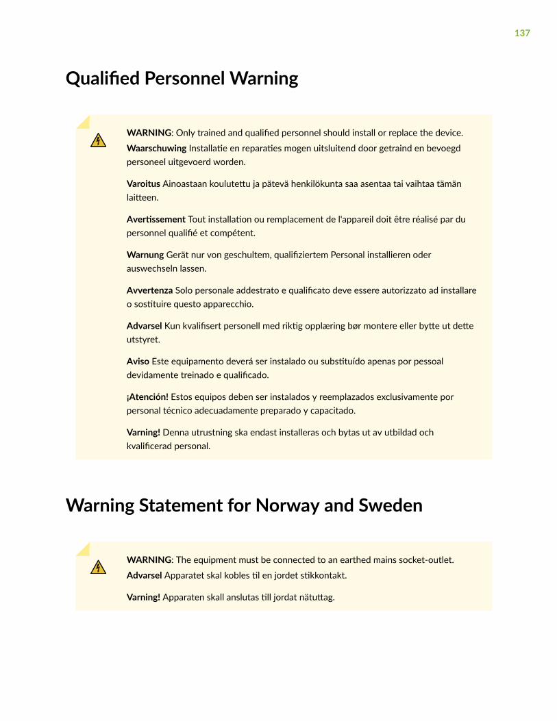
Qualified Personnel Warning
WARNING: Only trained and qualified personnel should install or replace the device.
Waarschuwing Installatie en reparaties mogen uitsluitend door getraind en bevoegdpersoneel uitgevoerd worden.
Varoitus Ainoastaan koulutettu ja pätevä henkilökunta saa asentaa tai vaihtaa tämänlaitteen.
Avertissement Tout installation ou remplacement de l'appareil doit être réalisé par dupersonnel qualifié et compétent.
Warnung Gerät nur von geschultem, qualifiziertem Personal installieren oderauswechseln lassen.
Avvertenza Solo personale addestrato e qualificato deve essere autorizzato ad installareo sostituire questo apparecchio.
Advarsel Kun kvalifisert personell med riktig opplæring bør montere eller bytte ut detteutstyret.
Aviso Este equipamento deverá ser instalado ou substituído apenas por pessoaldevidamente treinado e qualificado.
¡Atención! Estos equipos deben ser instalados y reemplazados exclusivamente porpersonal técnico adecuadamente preparado y capacitado.
Varning! Denna utrustning ska endast installeras och bytas ut av utbildad ochkvalificerad personal.
Warning Statement for Norway and Sweden
WARNING: The equipment must be connected to an earthed mains socket-outlet.
Advarsel Apparatet skal kobles til en jordet stikkontakt.
Varning! Apparaten skall anslutas till jordat nätuttag.
137

Installation Instructions Warning
WARNING: Read the installation instructions before you connect the device to a powersource.
Waarschuwing Raadpleeg de installatie-aanwijzingen voordat u het systeem met devoeding verbindt.
Varoitus Lue asennusohjeet ennen järjestelmän yhdistämistä virtalähteeseen.
Avertissement Avant de brancher le système sur la source d'alimentation, consulter lesdirectives d'installation.
Warnung Lesen Sie die Installationsanweisungen, bevor Sie das System an dieStromquelle anschließen.
Avvertenza Consultare le istruzioni di installazione prima di collegare il sistemaall'alimentatore.
Advarsel Les installasjonsinstruksjonene før systemet kobles til strømkilden.
Aviso Leia as instruções de instalação antes de ligar o sistema à sua fonte de energia.
¡Atención! Ver las instrucciones de instalación antes de conectar el sistema a la red dealimentación.
Varning! Läs installationsanvisningarna innan du kopplar systemet till dessströmförsörjningsenhet.
Chassis and Component Lifting Guidelines
• Before moving the device to a site, ensure that the site meets the power, environmental, andclearance requirements.
• Before lifting or moving the device, disconnect all external cables and wires.
• As when lifting any heavy object, ensure that most of the weight is borne by your legs rather thanyour back. Keep your knees bent and your back relatively straight. Do not twist your body as you lift.Balance the load evenly and be sure that your footing is firm.
• Use the following lifting guidelines to lift devices and components:
138
• Up to 39.7 lb (18 kg): One person.
• 39.7 lb (18 kg) to 70.5 lb (32 kg): Two or more people.
• 70.5 lb (32 kg) to 121.2 lb (55 kg): Three or more people.
• Above 121.2 lb (55 kg): Material handling systems (such as levers, slings, lifts and so on) must beused. When this is not practical, specially trained persons or systems must be used (riggers ormovers).
Ramp Warning
WARNING: When installing the device, do not use a ramp inclined at more than 10degrees.
Waarschuwing Gebruik een oprijplaat niet onder een hoek van meer dan 10 graden.
Varoitus Älä käytä sellaista kaltevaa pintaa, jonka kaltevuus ylittää 10 astetta.
Avertissement Ne pas utiliser une rampe dont l'inclinaison est supérieure à 10 degrés.
Warnung Keine Rampen mit einer Neigung von mehr als 10 Grad verwenden.
Avvertenza Non usare una rampa con pendenza superiore a 10 gradi.
Advarsel Bruk aldri en rampe som heller mer enn 10 grader.
Aviso Não utilize uma rampa com uma inclinação superior a 10 graus.
¡Atención! No usar una rampa inclinada más de 10 grados.
Varning! Använd inte ramp med en lutning på mer än 10 grader.
Rack-Mounting and Cabinet-Mounting Warnings
Ensure that the rack or cabinet in which the device is installed is evenly and securely supported. Unevenmechanical loading could lead to a hazardous condition.
139

WARNING: To prevent bodily injury when mounting or servicing the device in a rack,take the following precautions to ensure that the system remains stable. The followingdirectives help maintain your safety:
• The device must be installed in a rack that is secured to the building structure.
• The device should be mounted at the bottom of the rack if it is the only unit in therack.
• When mounting the device on a partially filled rack, load the rack from the bottomto the top with the heaviest component at the bottom of the rack.
• If the rack is provided with stabilizing equipment, install the stabilizers beforemounting or servicing the device in the rack.
Waarschuwing Om lichamelijk letsel te voorkomen wanneer u dit toestel in een rekmonteert of het daar een servicebeurt geeft, moet u speciale voorzorgsmaatregelennemen om ervoor te zorgen dat het toestel stabiel blijft. De onderstaande richtlijnenworden verstrekt om uw veiligheid te verzekeren:
• De Juniper Networks switch moet in een stellage worden geïnstalleerd die aan eenbouwsel is verankerd.
• Dit toestel dient onderaan in het rek gemonteerd te worden als het toestel het enigein het rek is.
• Wanneer u dit toestel in een gedeeltelijk gevuld rek monteert, dient u het rek vanonderen naar boven te laden met het zwaarste onderdeel onderaan in het rek.
• Als het rek voorzien is van stabiliseringshulpmiddelen, dient u de stabilisatoren temonteren voordat u het toestel in het rek monteert of het daar een servicebeurtgeeft.
Varoitus Kun laite asetetaan telineeseen tai huolletaan sen ollessa telineessä, onnoudatettava erityisiä varotoimia järjestelmän vakavuuden säilyttämiseksi, jottavältytään loukkaantumiselta. Noudata seuraavia turvallisuusohjeita:
• Juniper Networks switch on asennettava telineeseen, joka on kiinnitettyrakennukseen.
• Jos telineessä ei ole muita laitteita, aseta laite telineen alaosaan.
140

• Jos laite asetetaan osaksi täytettyyn telineeseen, aloita kuormittaminen senalaosasta kaikkein raskaimmalla esineellä ja siirry sitten sen yläosaan.
• Jos telinettä varten on vakaimet, asenna ne ennen laitteen asettamista telineeseentai sen huoltamista siinä.
Avertissement Pour éviter toute blessure corporelle pendant les opérations de montageou de réparation de cette unité en casier, il convient de prendre des précautionsspéciales afin de maintenir la stabilité du système. Les directives ci-dessous sontdestinées à assurer la protection du personnel:
• Le rack sur lequel est monté le Juniper Networks switch doit être fixé à la structuredu bâtiment.
• Si cette unité constitue la seule unité montée en casier, elle doit être placée dans lebas.
• Si cette unité est montée dans un casier partiellement rempli, charger le casier debas en haut en plaçant l'élément le plus lourd dans le bas.
• Si le casier est équipé de dispositifs stabilisateurs, installer les stabilisateurs avant demonter ou de réparer l'unité en casier.
Warnung Zur Vermeidung von Körperverletzung beim Anbringen oder Warten dieserEinheit in einem Gestell müssen Sie besondere Vorkehrungen treffen, umsicherzustellen, daß das System stabil bleibt. Die folgenden Richtlinien sollen zurGewährleistung Ihrer Sicherheit dienen:
• Der Juniper Networks switch muß in einem Gestell installiert werden, das in derGebäudestruktur verankert ist.
• Wenn diese Einheit die einzige im Gestell ist, sollte sie unten im Gestell angebrachtwerden.
• Bei Anbringung dieser Einheit in einem zum Teil gefüllten Gestell ist das Gestell vonunten nach oben zu laden, wobei das schwerste Bauteil unten im Gestellanzubringen ist.
• Wird das Gestell mit Stabilisierungszubehör geliefert, sind zuerst die Stabilisatorenzu installieren, bevor Sie die Einheit im Gestell anbringen oder sie warten.
Avvertenza Per evitare infortuni fisici durante il montaggio o la manutenzione di questaunità in un supporto, occorre osservare speciali precauzioni per garantire che il sistema
141

rimanga stabile. Le seguenti direttive vengono fornite per garantire la sicurezzapersonale:
• Il Juniper Networks switch deve essere installato in un telaio, il quale deve esserefissato alla struttura dell'edificio.
• Questa unità deve venire montata sul fondo del supporto, se si tratta dell'unica unitàda montare nel supporto.
• Quando questa unità viene montata in un supporto parzialmente pieno, caricare ilsupporto dal basso all'alto, con il componente più pesante sistemato sul fondo delsupporto.
• Se il supporto è dotato di dispositivi stabilizzanti, installare tali dispositivi prima dimontare o di procedere alla manutenzione dell'unità nel supporto.
Advarsel Unngå fysiske skader under montering eller reparasjonsarbeid på denneenheten når den befinner seg i et kabinett. Vær nøye med at systemet er stabilt.Følgende retningslinjer er gitt for å verne om sikkerheten:
• Juniper Networks switch må installeres i et stativ som er forankret tilbygningsstrukturen.
• Denne enheten bør monteres nederst i kabinettet hvis dette er den eneste enheten ikabinettet.
• Ved montering av denne enheten i et kabinett som er delvis fylt, skal kabinettetlastes fra bunnen og opp med den tyngste komponenten nederst i kabinettet.
• Hvis kabinettet er utstyrt med stabiliseringsutstyr, skal stabilisatorene installeres førmontering eller utføring av reparasjonsarbeid på enheten i kabinettet.
Aviso Para se prevenir contra danos corporais ao montar ou reparar esta unidade numaestante, deverá tomar precauções especiais para se certificar de que o sistema possuium suporte estável. As seguintes directrizes ajudá-lo-ão a efectuar o seu trabalho comsegurança:
• O Juniper Networks switch deverá ser instalado numa prateleira fixa à estrutura doedificio.
• Esta unidade deverá ser montada na parte inferior da estante, caso seja esta a únicaunidade a ser montada.
142

• Ao montar esta unidade numa estante parcialmente ocupada, coloque os itens maispesados na parte inferior da estante, arrumando-os de baixo para cima.
• Se a estante possuir um dispositivo de estabilização, instale-o antes de montar oureparar a unidade.
¡Atención! Para evitar lesiones durante el montaje de este equipo sobre un bastidor,oeriormente durante su mantenimiento, se debe poner mucho cuidado en que elsistema quede bien estable. Para garantizar su seguridad, proceda según las siguientesinstrucciones:
• El Juniper Networks switch debe instalarse en un bastidor fijado a la estructura deledificio.
• Colocar el equipo en la parte inferior del bastidor, cuando sea la única unidad en elmismo.
• Cuando este equipo se vaya a instalar en un bastidor parcialmente ocupado,comenzar la instalación desde la parte inferior hacia la superior colocando el equipomás pesado en la parte inferior.
• Si el bastidor dispone de dispositivos estabilizadores, instalar éstos antes de montaro proceder al mantenimiento del equipo instalado en el bastidor.
Varning! För att undvika kroppsskada när du installerar eller utför underhållsarbete pådenna enhet på en ställning måste du vidta särskilda försiktighetsåtgärder för attförsäkra dig om att systemet står stadigt. Följande riktlinjer ges för att trygga dinsäkerhet:
• Juniper Networks switch måste installeras i en ställning som är förankrad ibyggnadens struktur.
• Om denna enhet är den enda enheten på ställningen skall den installeras längst nedpå ställningen.
• Om denna enhet installeras på en delvis fylld ställning skall ställningen fyllas nedifrånoch upp, med de tyngsta enheterna längst ned på ställningen.
• Om ställningen är försedd med stabiliseringsdon skall dessa monteras fast innanenheten installeras eller underhålls på ställningen.
143

Grounded Equipment Warning
WARNING: This device must be properly grounded at all times. Follow the instructionsin this guide to properly ground the device to earth.
Waarschuwing Dit apparaat moet altijd goed geaard zijn. Volg de instructies in dezegids om het apparaat goed te aarden.
Varoitus Laitteen on oltava pysyvästi maadoitettu. Maadoita laite asianmukaisestinoudattamalla tämän oppaan ohjeita.
Avertissement L’appareil doit être correctement mis à la terre à tout moment. Suivez lesinstructions de ce guide pour correctement mettre l’appareil à la terre.
Warnung Das Gerät muss immer ordnungsgemäß geerdet sein. Befolgen Sie dieAnweisungen in dieser Anleitung, um das Gerät ordnungsgemäß zu erden.
Avvertenza Questo dispositivo deve sempre disporre di una connessione a massa.Seguire le istruzioni indicate in questa guida per connettere correttamente il dispositivoa massa.
Advarsel Denne enheten på jordes skikkelig hele tiden. Følg instruksjonene i denneveiledningen for å jorde enheten.
Aviso Este equipamento deverá estar ligado à terra. Siga las instrucciones en esta guíapara conectar correctamente este dispositivo a tierra.
¡Atención! Este dispositivo debe estar correctamente conectado a tierra en todomomento. Siga las instrucciones en esta guía para conectar correctamente estedispositivo a tierra.
Varning! Den här enheten måste vara ordentligt jordad. Följ instruktionerna i den härguiden för att jorda enheten ordentligt.
Laser and LED Safety Guidelines and Warnings
IN THIS SECTION
General Laser Safety Guidelines | 145
144

Class 1 Laser Product Warning | 145
Class 1 LED Product Warning | 146
Laser Beam Warning | 147
Juniper Networks devices are equipped with laser transmitters, which are considered a Class 1 LaserProduct by the U.S. Food and Drug Administration and are evaluated as a Class 1 Laser Product per EN60825-1 requirements.
Observe the following guidelines and warnings:
General Laser Safety Guidelines
When working around ports that support optical transceivers, observe the following safety guidelines toprevent eye injury:
• Do not look into unterminated ports or at fibers that connect to unknown sources.
• Do not examine unterminated optical ports with optical instruments.
• Avoid direct exposure to the beam.
LASER WARNING: Unterminated optical connectors can emit invisible laser radiation. Thelens in the human eye focuses all the laser power on the retina, so focusing the eyedirectly on a laser source—even a low-power laser—could permanently damage the eye.
Avertissement Les connecteurs à fibre optique sans terminaison peuvent émettre unrayonnement laser invisible. Le cristallin de l’œil humain faisant converger toute lapuissance du laser sur la rétine, toute focalisation directe de l’œil sur une source laser, —même de faible puissance—, peut entraîner des lésions oculaires irréversibles.
Class 1 Laser Product Warning
LASER WARNING: Class 1 laser product.
145
Waarschuwing Klasse-1 laser produkt.
Varoitus Luokan 1 lasertuote.
Avertissement Produit laser de classe I.
Warnung Laserprodukt der Klasse 1.
Avvertenza Prodotto laser di Classe 1.
Advarsel Laserprodukt av klasse 1.
Aviso Produto laser de classe 1.
¡Atención! Producto láser Clase I.
Varning! Laserprodukt av klass 1.
Class 1 LED Product Warning
LASER WARNING: Class 1 LED product.
Waarschuwing Klasse 1 LED-product.
Varoitus Luokan 1 valodiodituote.
Avertissement Alarme de produit LED Class I.
Warnung Class 1 LED-Produktwarnung.
Avvertenza Avvertenza prodotto LED di Classe 1.
Advarsel LED-produkt i klasse 1.
Aviso Produto de classe 1 com LED.
¡Atención! Aviso sobre producto LED de Clase 1.
Varning! Lysdiodprodukt av klass 1.
146
Laser Beam Warning
LASER WARNING: Do not stare into the laser beam or view it directly with opticalinstruments.
Waarschuwing Niet in de straal staren of hem rechtstreeks bekijken met optischeinstrumenten.
Varoitus Älä katso säteeseen äläkä tarkastele sitä suoraan optisen laitteen avulla.
Avertissement Ne pas fixer le faisceau des yeux, ni l'observer directement à l'aided'instruments optiques.
Warnung Nicht direkt in den Strahl blicken und ihn nicht direkt mit optischen Gerätenprüfen.
Avvertenza Non fissare il raggio con gli occhi né usare strumenti ottici per osservarlodirettamente.
Advarsel Stirr eller se ikke direkte p strlen med optiske instrumenter.
Aviso Não olhe fixamente para o raio, nem olhe para ele directamente com instrumentosópticos.
¡Atención! No mirar fijamente el haz ni observarlo directamente con instrumentos ópticos.
Varning! Rikta inte blicken in mot strålen och titta inte direkt på den genom optiskainstrument.
Radiation from Open Port Apertures Warning
LASER WARNING: Because invisible radiation might be emitted from the aperture of theport when no fiber cable is connected, avoid exposure to radiation and do not stare intoopen apertures.
Waarschuwing Aangezien onzichtbare straling vanuit de opening van de poort kan komenals er geen fiberkabel aangesloten is, dient blootstelling aan straling en het kijken in openopeningen vermeden te worden.
147

Varoitus Koska portin aukosta voi emittoitua näkymätöntä säteilyä, kun kuitukaapelia ei olekytkettynä, vältä säteilylle altistumista äläkä katso avoimiin aukkoihin.
Avertissement Des radiations invisibles à l'il nu pouvant traverser l'ouverture du portlorsqu'aucun câble en fibre optique n'y est connecté, il est recommandé de ne pas regarderfixement l'intérieur de ces ouvertures.
Warnung Aus der Port-Öffnung können unsichtbare Strahlen emittieren, wenn keinGlasfaserkabel angeschlossen ist. Vermeiden Sie es, sich den Strahlungen auszusetzen, undstarren Sie nicht in die Öffnungen!
Avvertenza Quando i cavi in fibra non sono inseriti, radiazioni invisibili possono essereemesse attraverso l'apertura della porta. Evitate di esporvi alle radiazioni e non guardatedirettamente nelle aperture.
Advarsel Unngå utsettelse for stråling, og stirr ikke inn i åpninger som er åpne, fordi usynligstråling kan emiteres fra portens åpning når det ikke er tilkoblet en fiberkabel.
Aviso Dada a possibilidade de emissão de radiação invisível através do orifício da via deacesso, quando esta não tiver nenhum cabo de fibra conectado, deverá evitar an EXposiçãoà radiação e não deverá olhar fixamente para orifícios que se encontrarem a descoberto.
¡Atención! Debido a que la apertura del puerto puede emitir radiación invisible cuando noexiste un cable de fibra conectado, evite mirar directamente a las aperturas para noexponerse a la radiación.
Varning! Osynlig strålning kan avges från en portöppning utan ansluten fiberkabel och dubör därför undvika att bli utsatt för strålning genom att inte stirra in i oskyddade öppningar.
Maintenance and Operational Safety Guidelines andWarnings
IN THIS SECTION
Battery Handling Warning | 149
Jewelry Removal Warning | 150
Lightning Activity Warning | 151
148

Operating Temperature Warning | 152
Product Disposal Warning | 153
While performing the maintenance activities for devices, observe the following guidelines and warnings:
Battery Handling Warning
WARNING: Replacing a battery incorrectly might result in an explosion. Replace abattery only with the same or equivalent type recommended by the manufacturer.Dispose of used batteries according to the manufacturer's instructions.
Waarschuwing Er is ontploffingsgevaar als de batterij verkeerd vervangen wordt.Vervang de batterij slechts met hetzelfde of een equivalent type dat door de fabrikantaanbevolen is. Gebruikte batterijen dienen overeenkomstig fabrieksvoorschriftenweggeworpen te worden.
Varoitus Räjähdyksen vaara, jos akku on vaihdettu väärään akkuun. Käytä vaihtamiseenainoastaan saman- tai vastaavantyyppistä akkua, joka on valmistajan suosittelema.Hävitä käytetyt akut valmistajan ohjeiden mukaan.
Avertissement Danger d'explosion si la pile n'est pas remplacée correctement. Ne laremplacer que par une pile de type semblable ou équivalent, recommandée par lefabricant. Jeter les piles usagées conformément aux instructions du fabricant.
Warnung Bei Einsetzen einer falschen Batterie besteht Explosionsgefahr. Ersetzen Siedie Batterie nur durch den gleichen oder vom Hersteller empfohlenen Batterietyp.Entsorgen Sie die benutzten Batterien nach den Anweisungen des Herstellers.
Advarsel Det kan være fare for eksplosjon hvis batteriet skiftes på feil måte. Skift kunmed samme eller tilsvarende type som er anbefalt av produsenten. Kasser bruktebatterier i henhold til produsentens instruksjoner.
Avvertenza Pericolo di esplosione se la batteria non è installata correttamente.Sostituire solo con una di tipo uguale o equivalente, consigliata dal produttore. Eliminarele batterie usate secondo le istruzioni del produttore.
149

Aviso Existe perigo de explosão se a bateria for substituída incorrectamente. Substituaa bateria por uma bateria igual ou de um tipo equivalente recomendado pelo fabricante.Destrua as baterias usadas conforme as instruções do fabricante.
¡Atención! Existe peligro de explosión si la batería se reemplaza de manera incorrecta.Reemplazar la baterían EXclusivamente con el mismo tipo o el equivalenterecomendado por el fabricante. Desechar las baterías gastadas según las instruccionesdel fabricante.
Varning! Explosionsfara vid felaktigt batteribyte. Ersätt endast batteriet med sammabatterityp som rekommenderas av tillverkaren eller motsvarande. Följ tillverkarensanvisningar vid kassering av använda batterier.
Jewelry Removal Warning
WARNING: Before working on equipment that is connected to power lines, removejewelry, including rings, necklaces, and watches. Metal objects heat up when connectedto power and ground and can cause serious burns or can be welded to the terminals.
Waarschuwing Alvorens aan apparatuur te werken die met elektrische leidingen isverbonden, sieraden (inclusief ringen, kettingen en horloges) verwijderen. Metalenvoorwerpen worden warm wanneer ze met stroom en aarde zijn verbonden, en kunnenernstige brandwonden veroorzaken of het metalen voorwerp aan de aansluitklemmenlassen.
Varoitus Ennen kuin työskentelet voimavirtajohtoihin kytkettyjen laitteiden parissa, otapois kaikki korut (sormukset, kaulakorut ja kellot mukaan lukien). Metalliesineetkuumenevat, kun ne ovat yhteydessä sähkövirran ja maan kanssa, ja ne voivat aiheuttaavakavia palovammoja tai hitsata metalliesineet kiinni liitäntänapoihin.
Avertissement Avant d'accéder à cet équipement connecté aux lignes électriques, ôtertout bijou (anneaux, colliers et montres compris). Lorsqu'ils sont branchés àl'alimentation et reliés à la terre, les objets métalliques chauffent, ce qui peut provoquerdes blessures graves ou souder l'objet métallique aux bornes.
Warnung Vor der Arbeit an Geräten, die an das Netz angeschlossen sind, jeglichenSchmuck (einschließlich Ringe, Ketten und Uhren) abnehmen. Metallgegenständeerhitzen sich, wenn sie an das Netz und die Erde angeschlossen werden, und könnenschwere Verbrennungen verursachen oder an die Anschlußklemmen angeschweißtwerden.
150

Avvertenza Prima di intervenire su apparecchiature collegate alle linee di alimentazione,togliersi qualsiasi monile (inclusi anelli, collane, braccialetti ed orologi). Gli oggettimetallici si riscaldano quando sono collegati tra punti di alimentazione e massa: possonocausare ustioni gravi oppure il metallo può saldarsi ai terminali.
Advarsel Fjern alle smykker (inkludert ringer, halskjeder og klokker) før du skal arbeidepå utstyr som er koblet til kraftledninger. Metallgjenstander som er koblet tilkraftledninger og jord blir svært varme og kan forårsake alvorlige brannskader ellersmelte fast til polene.
Aviso Antes de trabalhar em equipamento que esteja ligado a linhas de corrente, retiretodas as jóias que estiver a usar (incluindo anéis, fios e relógios). Os objectos metálicosaquecerão em contacto com a corrente e em contacto com a ligação à terra, podendocausar queimaduras graves ou ficarem soldados aos terminais.
¡Atención! Antes de operar sobre equipos conectados a líneas de alimentación, quitarselas joyas (incluidos anillos, collares y relojes). Los objetos de metal se calientan cuandose conectan a la alimentación y a tierra, lo que puede ocasionar quemaduras graves oque los objetos metálicos queden soldados a los bornes.
Varning! Tag av alla smycken (inklusive ringar, halsband och armbandsur) innan duarbetar på utrustning som är kopplad till kraftledningar. Metallobjekt hettas upp när dekopplas ihop med ström och jord och kan förorsaka allvarliga brännskador; metallobjektkan också sammansvetsas med kontakterna.
Lightning Activity Warning
WARNING: Do not work on the system or connect or disconnect cables during periodsof lightning activity.
Waarschuwing Tijdens onweer dat gepaard gaat met bliksem, dient u niet aan hetsysteem te werken of kabels aan te sluiten of te ontkoppelen.
Varoitus Älä työskentele järjestelmän parissa äläkä yhdistä tai irrota kaapeleitaukkosilmalla.
Avertissement Ne pas travailler sur le système ni brancher ou débrancher les câblespendant un orage.
151

Warnung Arbeiten Sie nicht am System und schließen Sie keine Kabel an bzw. trennenSie keine ab, wenn es gewittert.
Avvertenza Non lavorare sul sistema o collegare oppure scollegare i cavi durante untemporale con fulmini.
Advarsel Utfør aldri arbeid på systemet, eller koble kabler til eller fra systemet når dettordner eller lyner.
Aviso Não trabalhe no sistema ou ligue e desligue cabos durante períodos de mautempo (trovoada).
¡Atención! No operar el sistema ni conectar o desconectar cables durante el transcursode descargas eléctricas en la atmósfera.
Varning! Vid åska skall du aldrig utföra arbete på systemet eller ansluta eller koppla losskablar.
Operating Temperature Warning
WARNING: To prevent the device from overheating, do not operate it in an area thatexceeds the maximum recommended ambient temperature. To prevent airflowrestriction, allow at least 6 in. (15.2 cm) of clearance around the ventilation openings.
Waarschuwing Om te voorkomen dat welke switch van de Juniper Networks router danook oververhit raakt, dient u deze niet te bedienen op een plaats waar de maximaleaanbevolen omgevingstemperatuur van 40° C wordt overschreden. Om te voorkomendat de luchtstroom wordt beperkt, dient er minstens 15,2 cm speling rond de ventilatie-openingen te zijn.
Varoitus Ettei Juniper Networks switch-sarjan reititin ylikuumentuisi, sitä ei saa käyttäätilassa, jonka lämpötila ylittää korkeimman suositellun ympäristölämpötilan 40° C. Etteiilmanvaihto estyisi, tuuletusaukkojen ympärille on jätettävä ainakin 15,2 cm tilaa.
Avertissement Pour éviter toute surchauffe des routeurs de la gamme JuniperNetworks switch, ne l'utilisez pas dans une zone où la température ambiante estsupérieure à 40° C. Pour permettre un flot d'air constant, dégagez un espace d'au moins15,2 cm autour des ouvertures de ventilations.
Warnung Um einen Router der switch vor Überhitzung zu schützen, darf dieser nicht ineiner Gegend betrieben werden, in der die Umgebungstemperatur das empfohlene
152
Maximum von 40° C überschreitet. Um Lüftungsverschluß zu verhindern, achten Siedarauf, daß mindestens 15,2 cm lichter Raum um die Lüftungsöffnungen herum freibleibt.
Avvertenza Per evitare il surriscaldamento dei switch, non adoperateli in un locale cheecceda la temperatura ambientale massima di 40° C. Per evitare che la circolazionedell'aria sia impedita, lasciate uno spazio di almeno 15.2 cm di fronte alle aperture delleventole.
Advarsel Unngå overoppheting av eventuelle rutere i Juniper Networks switch Disseskal ikke brukes på steder der den anbefalte maksimale omgivelsestemperaturenoverstiger 40° C (104° F). Sørg for at klaringen rundt lufteåpningene er minst 15,2 cm(6 tommer) for å forhindre nedsatt luftsirkulasjon.
Aviso Para evitar o sobreaquecimento do encaminhador Juniper Networks switch, nãoutilize este equipamento numa área que exceda a temperatura máxima recomendada de40° C. Para evitar a restrição à circulação de ar, deixe pelo menos um espaço de 15,2 cmà volta das aberturas de ventilação.
¡Atención! Para impedir que un encaminador de la serie Juniper Networks switch serecaliente, no lo haga funcionar en un área en la que se supere la temperatura ambientemáxima recomendada de 40° C. Para impedir la restricción de la entrada de aire, deje unespacio mínimo de 15,2 cm alrededor de las aperturas para ventilación.
Varning! Förhindra att en Juniper Networks switch överhettas genom att inte användaden i ett område där den maximalt rekommenderade omgivningstemperaturen på 40° Cöverskrids. Förhindra att luftcirkulationen inskränks genom att se till att det finns frittutrymme på minst 15,2 cm omkring ventilationsöppningarna.
Product Disposal Warning
WARNING: Disposal of this device must be handled according to all national laws andregulations.
Waarschuwing Dit produkt dient volgens alle landelijke wetten en voorschriften teworden afgedankt.
Varoitus Tämän tuotteen lopullisesta hävittämisestä tulee huolehtia kaikkiavaltakunnallisia lakeja ja säännöksiä noudattaen.
153
Avertissement La mise au rebut définitive de ce produit doit être effectuéeconformément à toutes les lois et réglementations en vigueur.
Warnung Dieses Produkt muß den geltenden Gesetzen und Vorschriften entsprechendentsorgt werden.
Avvertenza L'eliminazione finale di questo prodotto deve essere eseguita osservando lenormative italiane vigenti in materia
Advarsel Endelig disponering av dette produktet må skje i henhold til nasjonale lover ogforskrifter.
Aviso A descartagem final deste produto deverá ser efectuada de acordo com osregulamentos e a legislação nacional.
¡Atención! El desecho final de este producto debe realizarse según todas las leyes yregulaciones nacionales
Varning! Slutlig kassering av denna produkt bör skötas i enlighet med landets alla lagaroch föreskrifter.
General Electrical Safety Guidelines and Warnings
WARNING: Certain ports on the device are designed for use as intrabuilding (within-the-building) interfaces only (Type 2 or Type 4 ports as described in GR-1089-CORE)and require isolation from the exposed outside plant (OSP) cabling. To comply withNEBS requirements and protect against lightning surges and commercial powerdisturbances, the intrabuilding ports must not be metallically connected to interfacesthat connect to the OSP or its wiring. The intrabuilding ports on the device are suitablefor connection to intrabuilding or unexposed wiring or cabling only. The addition ofprimary protectors is not sufficient protection for connecting these interfacesmetallically to OSP wiring.
Avertissement Certains ports de l’appareil sont destinés à un usage en intérieuruniquement (ports Type 2 ou Type 4 tels que décrits dans le document GR-1089-CORE)et doivent être isolés du câblage de l’installation extérieure exposée. Pour respecter lesexigences NEBS et assurer une protection contre la foudre et les perturbations detension secteur, les ports pour intérieur ne doivent pas être raccordés physiquementaux interfaces prévues pour la connexion à l’installation extérieure ou à son câblage. Les
154
ports pour intérieur de l’appareil sont réservés au raccordement de câbles pour intérieurou non exposés uniquement. L’ajout de protections ne constitue pas une précautionsuffisante pour raccorder physiquement ces interfaces au câblage de l’installationextérieure.
CAUTION: Before removing or installing components of a device, connect anelectrostatic discharge (ESD) grounding strap to an ESD point and wrap and fasten theother end of the strap around your bare wrist. Failure to use an ESD grounding strapcould result in damage to the device.
Attention Avant de retirer ou d’installer des composants d’un appareil, raccordez unbracelet antistatique à un point de décharge électrostatique et fixez le bracelet à votrepoignet nu. L’absence de port d’un bracelet antistatique pourrait provoquer des dégâtssur l’appareil.
• Install the device in compliance with the following local, national, and international electrical codes:
• United States—National Fire Protection Association (NFPA 70), United States National ElectricalCode.
• Other countries—International Electromechanical Commission (IEC) 60364, Part 1 through Part 7.
• Evaluated to the TN power system.
• Canada—Canadian Electrical Code, Part 1, CSA C22.1.
• Suitable for installation in Information Technology Rooms in accordance with Article 645 of theNational Electrical Code and NFPA 75.
Peut être installé dans des salles de matériel de traitement de l’information conformément àl’article 645 du National Electrical Code et à la NFPA 75.
• Locate the emergency power-off switch for the room in which you are working so that if an electricalaccident occurs, you can quickly turn off the power.
• Make sure that grounding surfaces are cleaned and brought to a bright finish before groundingconnections are made.
• Do not work alone if potentially hazardous conditions exist anywhere in your workspace.
• Never assume that power is disconnected from a circuit. Always check the circuit before starting towork.
• Carefully look for possible hazards in your work area, such as moist floors, ungrounded powerextension cords, and missing safety grounds.
155

• Operate the device within marked electrical ratings and product usage instructions.
• To ensure that the device and peripheral equipment function safely and correctly, use the cables andconnectors specified for the attached peripheral equipment, and make certain they are in goodcondition.
You can remove and replace many device components without powering off or disconnecting power tothe device, as detailed elsewhere in the hardware documentation for this device. Never installequipment that appears to be damaged.
Prevention of Electrostatic Discharge Damage
Device components that are shipped in antistatic bags are sensitive to damage from static electricity.Some components can be impaired by voltages as low as 30 V. You can easily generate potentiallydamaging static voltages whenever you handle plastic or foam packing material or if you movecomponents across plastic or carpets. Observe the following guidelines to minimize the potential forelectrostatic discharge (ESD) damage, which can cause intermittent or complete component failures:
• Always use an ESD wrist strap when you are handling components that are subject to ESD damage,and make sure that it is in direct contact with your skin.
If a grounding strap is not available, hold the component in its antistatic bag (see Figure 51 on page157) in one hand and touch the exposed, bare metal of the device with the other hand immediatelybefore inserting the component into the device.
WARNING: For safety, periodically check the resistance value of the ESD groundingstrap. The measurement must be in the range 1 through 10 Mohms.
Avertissement Par mesure de sécurité, vérifiez régulièrement la résistance du braceletantistatique. Cette valeur doit être comprise entre 1 et 10 mégohms (Mohms).
• When handling any component that is subject to ESD damage and that is removed from the device,make sure the equipment end of your ESD wrist strap is attached to the ESD point on the chassis.
If no grounding strap is available, touch the exposed, bare metal of the device to ground yourselfbefore handling the component.
• Avoid contact between the component that is subject to ESD damage and your clothing. ESDvoltages emitted from clothing can damage components.
156

• When removing or installing a component that is subject to ESD damage, always place it component-side up on an antistatic surface, in an antistatic card rack, or in an antistatic bag (see Figure 51 onpage 157). If you are returning a component, place it in an antistatic bag before packing it.
Figure 51: Placing a Component into an Antistatic Bag
CAUTION: ANSI/TIA/EIA-568 cables such as Category 5e and Category 6 can getelectrostatically charged. To dissipate this charge, always ground the cables to a suitableand safe earth ground before connecting them to the system.
Attention Les câbles ANSI/TIA/EIA-568, par exemple Cat 5e et Cat 6, peuventemmagasiner des charges électrostatiques. Pour évacuer ces charges, reliez toujours lescâbles à une prise de terre adaptée avant de les raccorder au système.
AC Power Electrical Safety Guidelines
The following electrical safety guidelines apply to AC-powered devices:
• Note the following warnings printed on the device:
“CAUTION: THIS UNIT HAS MORE THAN ONE POWER SUPPLY CORD. DISCONNECT ALLPOWER SUPPLY CORDS BEFORE SERVICING TO AVOID ELECTRIC SHOCK.”
157

“ATTENTION: CET APPAREIL COMPORTE PLUS D'UN CORDON D'ALIMENTATION. AFIN DEPRÉVENIR LES CHOCS ÉLECTRIQUES, DÉBRANCHER TOUT CORDON D'ALIMENTATION AVANTDE FAIRE LE DÉPANNAGE.”
• AC-powered devices are shipped with a three-wire electrical cord with a grounding-type plug thatfits only a grounding-type power outlet. Do not circumvent this safety feature. Equipment groundingmust comply with local and national electrical codes.
• You must provide an external certified circuit breaker (2-pole circuit breaker or 4-pole circuit breakerbased on your device) rated minimum 20 A in the building installation.
• The power cord serves as the main disconnecting device for the AC-powered device. The socketoutlet must be near the AC-powered device and be easily accessible.
• For devices that have more than one power supply connection, you must ensure that all powerconnections are fully disconnected so that power to the device is completely removed to preventelectric shock. To disconnect power, unplug all power cords (one for each power supply).
Power Cable Warning (Japanese)
WARNING: The attached power cable is only for this product. Do not use the cable for another product.
AC Power Disconnection Warning
WARNING: Before working on the device or near power supplies, unplug all the powercords from an AC-powered device.
Waarschuwing Voordat u aan een frame of in de nabijheid van voedingen werkt, dient ubij wisselstroom toestellen de stekker van het netsnoer uit het stopcontact te halen.
Varoitus Kytke irti vaihtovirtalaitteiden virtajohto, ennen kuin teet mitäänasennuspohjalle tai työskentelet virtalähteiden läheisyydessä.
158

Avertissement Avant de travailler sur un châssis ou à proximité d'une alimentationélectrique, débrancher le cordon d'alimentation des unités en courant alternatif.
Warnung Bevor Sie an einem Chassis oder in der Nähe von Netzgeräten arbeiten,ziehen Sie bei Wechselstromeinheiten das Netzkabel ab bzw.
Avvertenza Prima di lavorare su un telaio o intorno ad alimentatori, scollegare il cavo dialimentazione sulle unità CA.
Advarsel Før det utføres arbeid på kabinettet eller det arbeides i nærheten avstrømforsyningsenheter, skal strømledningen trekkes ut på vekselstrømsenheter.
Aviso Antes de trabalhar num chassis, ou antes de trabalhar perto de unidades defornecimento de energia, desligue o cabo de alimentação nas unidades de correntealternada.
¡Atención! Antes de manipular el chasis de un equipo o trabajar cerca de una fuente dealimentación, desenchufar el cable de alimentación en los equipos de corriente alterna(CA).
Varning! Innan du arbetar med ett chassi eller nära strömförsörjningsenheter skall du förväxelströmsenheter dra ur nätsladden.
DC Power Electrical Safety Guidelines
IN THIS SECTION
DC Power Electrical Safety Guidelines | 160
DC Power Disconnection Warning | 161
DC Power Grounding Requirements and Warning | 162
DC Power Wiring Sequence Warning | 163
DC Power Wiring Terminations Warning | 164
159

DC Power Electrical Safety Guidelines
The following electrical safety guidelines apply to a DC-powered services gateway:
• A DC-powered services gateway is equipped with a DC terminal block that is rated for the powerrequirements of a maximally configured services gateway. To supply sufficient power, terminate theDC input wiring on a facility DC source capable of supplying at least 15 A @ -48 VDC for the system.We recommend that the 48 VDC facility DC source be equipped with a circuit breaker rated at15 A (-48 VDC) minimum, or as required by local code. Incorporate an easily accessible disconnectdevice into the facility wiring. In the United States and Canada, the -48 VDC facility should beequipped with a circuit breaker rated a minimum of 125% of the power provisioned for the input inaccordance with the National Electrical Code in the US and the Canadian Electrical Code in Canada.Be sure to connect the ground wire or conduit to a solid office (earth) ground. A closed loop ring isrecommended for terminating the ground conductor at the ground stud.
• Run two wires from the circuit breaker box to a source of 48 VDC. Use appropriate gauge wire tohandle up to 15 A.
• A DC-powered services gateway that is equipped with a DC terminal block is intended only forinstallation in a restricted access location. In the United States, a restricted access area is one inaccordance with Articles 110-16, 110-17, and 110-18 of the National Electrical Code ANSI/NFPA70.
NOTE: Primary overcurrent protection is provided by the building circuit breaker. This breakershould protect against excess currents, short circuits, and earth faults in accordance with NECANSI/NFPA70.
• Ensure that the polarity of the DC input wiring is correct. Under certain conditions, connections withreversed polarity might trip the primary circuit breaker or damage the equipment.
• For personal safety, connect the green and yellow wire to safety (earth) ground at both the servicesgateway and the supply side of the DC wiring.
• The marked input voltage of -48 VDC for a DC-powered services gateway is the nominal voltageassociated with the battery circuit, and any higher voltages are only to be associated with floatvoltages for the charging function.
• Because the services gateway is a positive ground system, you must connect the positive lead to theterminal labeled RETURN, the negative lead to the terminal labeled -48V, and the earth ground tothe chassis grounding points.
160

DC Power Disconnection Warning
WARNING: Before performing any of the following procedures, ensure that power isremoved from the DC circuit. To ensure that all power is off, locate the circuit breakeron the panel board that services the DC circuit, switch the circuit breaker to the OFFposition, and tape the switch handle of the circuit breaker in the OFF position.
Waarschuwing Voordat u een van de onderstaande procedures uitvoert, dient u tecontroleren of de stroom naar het gelijkstroom circuit uitgeschakeld is. Om u ervan teverzekeren dat alle stroom UIT is geschakeld, kiest u op het schakelbord destroomverbreker die het gelijkstroom circuit bedient, draait de stroomverbreker naar deUIT positie en plakt de schakelaarhendel van de stroomverbreker met plakband in deUIT positie vast.
Varoitus Varmista, että tasavirtapiirissä ei ole virtaa ennen seuraavien toimenpiteidensuorittamista. Varmistaaksesi, että virta on KATKAISTU täysin, paikanna tasavirrastahuolehtivassa kojetaulussa sijaitseva suojakytkin, käännä suojakytkin KATKAISTU-asentoon ja teippaa suojakytkimen varsi niin, että se pysyy KATKAISTU-asennossa.
Attention Avant de pratiquer l'une quelconque des procédures ci-dessous, vérifier quele circuit en courant continu n'est plus sous tension. Pour en être sûr, localiser ledisjoncteur situé sur le panneau de service du circuit en courant continu, placer ledisjoncteur en position fermée (OFF) et, à l'aide d'un ruban adhésif, bloquer la poignéedu disjoncteur en position OFF.
Warnung Vor Ausführung der folgenden Vorgänge ist sicherzustellen, daß dieGleichstromschaltung keinen Strom erhält. Um sicherzustellen, daß sämtlicher Stromabgestellt ist, machen Sie auf der Schalttafel den Unterbrecher für dieGleichstromschaltung ausfindig, stellen Sie den Unterbrecher auf AUS, und kleben Sieden Schaltergriff des Unterbrechers mit Klebeband in der AUS-Stellung fest.
Avvertenza Prima di svolgere una qualsiasi delle procedure seguenti, verificare che ilcircuito CC non sia alimentato. Per verificare che tutta l'alimentazione sia scollegata(OFF), individuare l'interruttore automatico sul quadro strumenti che alimenta il circuitoCC, mettere l'interruttore in posizione OFF e fissarlo con nastro adesivo in taleposizione.
Advarsel Før noen av disse prosedyrene utføres, kontroller at strømmen er frakobletlikestrømkretsen. Sørg for at all strøm er slått AV. Dette gjøres ved å lokaliserestrømbryteren på brytertavlen som betjener likestrømkretsen, slå strømbryteren AV ogteipe bryterhåndtaket på strømbryteren i AV-stilling.
161
Aviso Antes de executar um dos seguintes procedimentos, certifique-se que desligou afonte de alimentação de energia do circuito de corrente contínua. Para se assegurar quetoda a corrente foi DESLIGADA, localize o disjuntor no painel que serve o circuito decorrente contínua e coloque-o na posição OFF (Desligado), segurando nessa posição amanivela do interruptor do disjuntor com fita isoladora.
¡Atención! Antes de proceder con los siguientes pasos, comprobar que la alimentacióndel circuito de corriente continua (CC) esté cortada (OFF). Para asegurarse de que todala alimentación esté cortada (OFF), localizar el interruptor automático en el panel quealimenta al circuito de corriente continua, cambiar el interruptor automático a laposición de Apagado (OFF), y sujetar con cinta la palanca del interruptor automático enposición de Apagado (OFF).
Varning! Innan du utför någon av följande procedurer måste du kontrollera attströmförsörjningen till likströmskretsen är bruten. Kontrollera att all strömförsörjning ärBRUTEN genom att slå AV det överspänningsskydd som skyddar likströmskretsen ochtejpa fast överspänningsskyddets omkopplare i FRÅN-läget.
DC Power Grounding Requirements and Warning
An insulated grounding conductor that is identical in size to the grounded and ungrounded branchcircuit supply conductors, but is identifiable by green and yellow stripes, is installed as part of the branchcircuit that supplies the unit. The grounding conductor is a separately derived system at the supplytransformer or motor generator set.
WARNING: When installing the services gateway, the ground connection must alwaysbe made first and disconnected last.
Waarschuwing Bij de installatie van het toestel moet de aardverbinding altijd het eersteworden gemaakt en het laatste worden losgemaakt.
Varoitus Laitetta asennettaessa on maahan yhdistäminen aina tehtävä ensiksi jamaadoituksen irti kytkeminen viimeiseksi.
Attention Lors de l'installation de l'appareil, la mise à la terre doit toujours êtreconnectée en premier et déconnectée en dernier.
Warnung Der Erdanschluß muß bei der Installation der Einheit immer zuerst hergestelltund zuletzt abgetrennt werden.
162

Avvertenza In fase di installazione dell'unità, eseguire sempre per primo il collegamentoa massa e disconnetterlo per ultimo.
Advarsel Når enheten installeres, må jordledningen alltid tilkobles først og frakobles sist.
Aviso Ao instalar a unidade, a ligação à terra deverá ser sempre a primeira a ser ligada, ea última a ser desligada.
¡Atención! Al instalar el equipo, conectar la tierra la primera y desconectarla la última.
Varning! Vid installation av enheten måste jordledningen alltid anslutas först ochkopplas bort sist.
DC Power Wiring Sequence Warning
WARNING: Wire the DC power supply using the appropriate lugs. When connectingpower, the proper wiring sequence is ground to ground, +RTN to +RTN, then -48 V to-48 V. When disconnecting power, the proper wiring sequence is -48 V to -48 V, +RTNto +RTN, then ground to ground. Note that the ground wire should always beconnected first and disconnected last.
Waarschuwing De juiste bedradingsvolgorde verbonden is aarde naar aarde, +RTN naar+RTN, en -48 V naar – 48 V. De juiste bedradingsvolgorde losgemaakt is en -48 V naar– 48 V, +RTN naar +RTN, aarde naar aarde.
Varoitus Oikea yhdistettava kytkentajarjestys on maajohto maajohtoon, +RTN varten+RTN, -48 V varten – 48 V. Oikea irrotettava kytkentajarjestys on -48 V varten – 48 V,+RTN varten +RTN, maajohto maajohtoon.
Attention Câblez l'approvisionnement d'alimentation CC En utilisant les crochetsappropriés à l'extrémité de câblage. En reliant la puissance, l'ordre approprié de câblageest rectifié pour rectifier, +RTN à +RTN, puis -48 V à -48 V. En débranchant lapuissance, l'ordre approprié de câblage est -48 V à -48 V, +RTN à +RTN, a alors rectifiépour rectifier. Notez que le fil de masse devrait toujours être relié d'abord et débranchépour la dernière fois. Notez que le fil de masse devrait toujours être relié d'abord etdébranché pour la dernière fois.
Warnung Die Stromzufuhr ist nur mit geeigneten Ringösen an das DC Netzteilanzuschliessen. Die richtige Anschlusssequenz ist: Erdanschluss zu Erdanschluss, +RTNzu +RTN und dann -48V zu -48V. Die richtige Sequenz zum Abtrennen der
163
Stromversorgung ist -48V zu -48V, +RTN zu +RTN und dann Erdanschluss zuErdanschluss. Es ist zu beachten dass der Erdanschluss immer zuerst angeschlossen undals letztes abgetrennt wird.
Avvertenza Mostra la morsettiera dell alimentatore CC. Cablare l'alimentatore CCusando i connettori adatti all'estremità del cablaggio, come illustrato. La correttasequenza di cablaggio è da massa a massa, da positivo a positivo (da linea ad L) e danegativo a negativo (da neutro a N). Tenere presente che il filo di massa deve semprevenire collegato per primo e scollegato per ultimo.
Advarsel Riktig tilkoples tilkoplingssekvens er jord til jord, +RTN til +RTN, -48 V til – 48V. Riktig frakoples tilkoplingssekvens er -48 V til – 48 V, +RTN til +RTN, jord til jord.
Aviso Ate con alambre la fuente de potencia cc Usando los terminales apropiados en elextremo del cableado. Al conectar potencia, la secuencia apropiada del cableado semuele para moler, +RTN a +RTN, entonces -48 V a -48 V. Al desconectar potencia, lasecuencia apropiada del cableado es -48 V a -48 V, +RTN a +RTN, entonces molió paramoler. Observe que el alambre de tierra se debe conectar siempre primero ydesconectar por último. Observe que el alambre de tierra se debe conectar siempreprimero y desconectar por último.
¡Atención! Wire a fonte de alimentação de DC Usando os talões apropriados naextremidade da fiação. Ao conectar a potência, a seqüência apropriada da fiação émoída para moer, +RTN a +RTN, então -48 V a -48 V. Ao desconectar a potência, aseqüência apropriada da fiação é -48 V a -48 V, +RTN a +RTN, moeu então para moer.Anote que o fio à terra deve sempre ser conectado primeiramente e desconectado porúltimo. Anote que o fio à terra deve sempre ser conectado primeiramente edesconectado por último.
Varning! Korrekt kopplingssekvens ar jord till jord, +RTN till +RTN, -48 V till – 48 V.Korrekt kopplas kopplingssekvens ar -48 V till -48 V, +RTN till +RTN, jord till jord.
DC Power Wiring Terminations Warning
WARNING: When stranded wiring is required, use approved wiring terminations, suchas closed-loop or spade-type with upturned lugs. These terminations should be theappropriate size for the wires and should clamp both the insulation and conductor.
Waarschuwing Wanneer geslagen bedrading vereist is, dient u bedrading te gebruikendie voorzien is van goedgekeurde aansluitingspunten, zoals het gesloten-lus type of het
164
grijperschop type waarbij de aansluitpunten omhoog wijzen. Deze aansluitpuntendienen de juiste maat voor de draden te hebben en dienen zowel de isolatie als degeleider vast te klemmen.
Varoitus Jos säikeellinen johdin on tarpeen, käytä hyväksyttyä johdinliitäntää,esimerkiksi suljettua silmukkaa tai kourumaista liitäntää, jossa on ylöspäin käännetytkiinnityskorvat. Tällaisten liitäntöjen tulee olla kooltaan johtimiin sopivia ja niiden tuleepuristaa yhteen sekä eristeen että johdinosan.
Attention Quand des fils torsadés sont nécessaires, utiliser des douilles terminaleshomologuées telles que celles à circuit fermé ou du type à plage ouverte avec cossesrebroussées. Ces douilles terminales doivent être de la taille qui convient aux fils etdoivent être refermées sur la gaine isolante et sur le conducteur.
Warnung Wenn Litzenverdrahtung erforderlich ist, sind zugelasseneVerdrahtungsanschlüsse, z.B. Ringoesen oder gabelförmige Kabelschuhe mit nach obengerichteten Enden zu verwenden. Diese Abschlüsse sollten die angemessene Größe fürdie Drähte haben und sowohl die Isolierung als auch den Leiter festklemmen.
Avvertenza Quando occorre usare trecce, usare connettori omologati, come quelli aocchiello o a forcella con linguette rivolte verso l'alto. I connettori devono avere lamisura adatta per il cablaggio e devono serrare sia l'isolante che il conduttore.
Advarsel Hvis det er nødvendig med flertrådede ledninger, brukes godkjenteledningsavslutninger, som for eksempel lukket sløyfe eller spadetype medoppoverbøyde kabelsko. Disse avslutningene skal ha riktig størrelse i forhold tilledningene, og skal klemme sammen både isolasjonen og lederen.
Aviso Quando forem requeridas montagens de instalação eléctrica de cabo torcido, useterminações de cabo aprovadas, tais como, terminações de cabo em circuito fechado eplanas com terminais de orelha voltados para cima. Estas terminações de cabo deverãoser do tamanho apropriado para os respectivos cabos, e deverão prendersimultaneamente o isolamento e o fio condutor.
¡Atención! Cuando se necesite hilo trenzado, utilizar terminales para cableshomologados, tales como las de tipo "bucle cerrado" o "espada", con las lengüetas deconexión vueltas hacia arriba. Estos terminales deberán ser del tamaño apropiado paralos cables que se utilicen, y tendrán que sujetar tanto el aislante como el conductor.
Varning! När flertrådiga ledningar krävs måste godkända ledningskontakter användas,t.ex. kabelsko av sluten eller öppen typ med uppåtvänd tapp. Storleken på dessakontakter måste vara avpassad till ledningarna och måste kunna hålla både isoleringenoch ledaren fastklämda.
165

RELATED DOCUMENTATION
Action to Take After an Electrical Accident
General Electrical Safety Guidelines and Warnings
AC Power Electrical Safety Guidelines
DC Power Disconnection Warning
WARNING: Before performing any of the DC power procedures, ensure that power isremoved from the DC circuit. To ensure that all power is off, locate the circuit breakeron the panel board that services the DC circuit, switch the circuit breaker to the OFFposition, and tape the device handle of the circuit breaker in the OFF position.
Waarschuwing Voordat u een van de onderstaande procedures uitvoert, dient u tecontroleren of de stroom naar het gelijkstroom circuit uitgeschakeld is. Om u ervan teverzekeren dat alle stroom UIT is geschakeld, kiest u op het schakelbord destroomverbreker die het gelijkstroom circuit bedient, draait de stroomverbreker naar deUIT positie en plakt de schakelaarhendel van de stroomverbreker met plakband in deUIT positie vast.
Varoitus Varmista, että tasavirtapiirissä ei ole virtaa ennen seuraavien toimenpiteidensuorittamista. Varmistaaksesi, että virta on KATKAISTU täysin, paikanna tasavirrastahuolehtivassa kojetaulussa sijaitseva suojakytkin, käännä suojakytkin KATKAISTU-asentoon ja teippaa suojakytkimen varsi niin, että se pysyy KATKAISTU-asennossa.
Avertissement Avant de pratiquer l'une quelconque des procédures ci-dessous, vérifierque le circuit en courant continu n'est plus sous tension. Pour en être sûr, localiser ledisjoncteur situé sur le panneau de service du circuit en courant continu, placer ledisjoncteur en position fermée (OFF) et, à l'aide d'un ruban adhésif, bloquer la poignéedu disjoncteur en position OFF.
Warnung Vor Ausführung der folgenden Vorgänge ist sicherzustellen, daß dieGleichstromschaltung keinen Strom erhält. Um sicherzustellen, daß sämtlicher Stromabgestellt ist, machen Sie auf der Schalttafel den Unterbrecher für dieGleichstromschaltung ausfindig, stellen Sie den Unterbrecher auf AUS, und kleben Sieden Schaltergriff des Unterbrechers mit Klebeband in der AUS-Stellung fest.
Avvertenza Prima di svolgere una qualsiasi delle procedure seguenti, verificare che ilcircuito CC non sia alimentato. Per verificare che tutta l'alimentazione sia scollegata
166

(OFF), individuare l'interruttore automatico sul quadro strumenti che alimenta il circuitoCC, mettere l'interruttore in posizione OFF e fissarlo con nastro adesivo in taleposizione.
Advarsel Før noen av disse prosedyrene utføres, kontroller at strømmen er frakobletlikestrømkretsen. Sørg for at all strøm er slått AV. Dette gjøres ved å lokaliserestrømbryteren på brytertavlen som betjener likestrømkretsen, slå strømbryteren AV ogteipe bryterhåndtaket på strømbryteren i AV-stilling.
Aviso Antes de executar um dos seguintes procedimentos, certifique-se que desligou afonte de alimentação de energia do circuito de corrente contínua. Para se assegurar quetoda a corrente foi DESLIGADA, localize o disjuntor no painel que serve o circuito decorrente contínua e coloque-o na posição OFF (Desligado), segurando nessa posição amanivela do interruptor do disjuntor com fita isoladora.
¡Atención! Antes de proceder con los siguientes pasos, comprobar que la alimentacióndel circuito de corriente continua (CC) esté cortada (OFF). Para asegurarse de que todala alimentación esté cortada (OFF), localizar el interruptor automático en el panel quealimenta al circuito de corriente continua, cambiar el interruptor automático a laposición de Apagado (OFF), y sujetar con cinta la palanca del interruptor automático enposición de Apagado (OFF).
Varning! Innan du utför någon av följande procedurer måste du kontrollera attströmförsörjningen till likströmskretsen är bruten. Kontrollera att all strömförsörjning ärBRUTEN genom att slå AV det överspänningsskydd som skyddar likströmskretsen ochtejpa fast överspänningsskyddets omkopplare i FRÅN-läget.
DC Power Grounding Requirements and Warning
An insulated grounding conductor that is identical in size to the grounded and ungrounded branchcircuit supply conductors but is identifiable by green and yellow stripes is installed as part of the branchcircuit that supplies the device. The grounding conductor is a separately derived system at the supplytransformer or motor generator set.
WARNING: When you install the device, the ground connection must always be madefirst and disconnected last.
Waarschuwing Bij de installatie van het toestel moet de aardverbinding altijd het eersteworden gemaakt en het laatste worden losgemaakt.
167

Varoitus Laitetta asennettaessa on maahan yhdistäminen aina tehtävä ensiksi jamaadoituksen irti kytkeminen viimeiseksi.
Avertissement Lors de l'installation de l'appareil, la mise à la terre doit toujours êtreconnectée en premier et déconnectée en dernier.
Warnung Der Erdanschluß muß bei der Installation der Einheit immer zuerst hergestelltund zuletzt abgetrennt werden.
Avvertenza In fase di installazione dell'unità, eseguire sempre per primo il collegamentoa massa e disconnetterlo per ultimo.
Advarsel Når enheten installeres, må jordledningen alltid tilkobles først og frakobles sist.
Aviso Ao instalar a unidade, a ligação à terra deverá ser sempre a primeira a ser ligada, ea última a ser desligada.
¡Atención! Al instalar el equipo, conectar la tierra la primera y desconectarla la última.
Varning! Vid installation av enheten måste jordledningen alltid anslutas först ochkopplas bort sist.
DC Power Wiring Sequence Warning
WARNING: Wire the DC power supply using the appropriate lugs. When connectingpower, the proper wiring sequence is ground to ground, +RTN to +RTN, then –48 V to –48 V. When disconnecting power, the proper wiring sequence is –48 V to –48 V, +RTNto +RTN, then ground to ground. Note that the ground wire must always be connectedfirst and disconnected last.
Waarschuwing De juiste bedradingsvolgorde verbonden is aarde naar aarde, +RTN naar+RTN, en –48 V naar – 48 V. De juiste bedradingsvolgorde losgemaakt is en –48 naar –48 V, +RTN naar +RTN, aarde naar aarde.
Varoitus Oikea yhdistettava kytkentajarjestys on maajohto maajohtoon, +RTN varten+RTN, –48 V varten – 48 V. Oikea irrotettava kytkentajarjestys on –48 V varten – 48 V,+RTN varten +RTN, maajohto maajohtoon.
Avertissement Câblez l'approvisionnement d'alimentation CC En utilisant les crochetsappropriés à l'extrémité de câblage. En reliant la puissance, l'ordre approprié de câblage
168

est rectifié pour rectifier, +RTN à +RTN, puis –48 V à –48 V. En débranchant lapuissance, l'ordre approprié de câblage est –48 V à –48 V, +RTN à +RTN, a alors rectifiépour rectifier. Notez que le fil de masse devrait toujours être relié d'abord et débranchépour la dernière fois. Notez que le fil de masse devrait toujours être relié d'abord etdébranché pour la dernière fois.
Warnung Die Stromzufuhr ist nur mit geeigneten Ringösen an das DC Netzteilanzuschliessen. Die richtige Anschlusssequenz ist: Erdanschluss zu Erdanschluss, +RTNzu +RTN und dann -48V zu -48V. Die richtige Sequenz zum Abtrennen derStromversorgung ist -48V zu -48V, +RTN zu +RTN und dann Erdanschluss zuErdanschluss. Es ist zu beachten dass der Erdanschluss immer zuerst angeschlossen undals letztes abgetrennt wird.
Avvertenza Mostra la morsettiera dell alimentatore CC. Cablare l'alimentatore CCusando i connettori adatti all'estremità del cablaggio, come illustrato. La correttasequenza di cablaggio è da massa a massa, da positivo a positivo (da linea ad L) e danegativo a negativo (da neutro a N). Tenere presente che il filo di massa deve semprevenire collegato per primo e scollegato per ultimo.
Advarsel Riktig tilkoples tilkoplingssekvens er jord til jord, +RTN til +RTN, –48 V til –48 V. Riktig frakoples tilkoplingssekvens er –48 V til – 48 V, +RTN til +RTN, jord til jord.
Aviso Ate con alambre la fuente de potencia cc Usando los terminales apropiados en elextremo del cableado. Al conectar potencia, la secuencia apropiada del cableado semuele para moler, +RTN a +RTN, entonces –48 V a –48 V. Al desconectar potencia, lasecuencia apropiada del cableado es –48 V a –48 V, +RTN a +RTN, entonces molió paramoler. Observe que el alambre de tierra se debe conectar siempre primero ydesconectar por último. Observe que el alambre de tierra se debe conectar siempreprimero y desconectar por último.
¡Atención! Wire a fonte de alimentação de DC Usando os talões apropriados nanEXtremidade da fiação. Ao conectar a potência, a seqüência apropriada da fiação émoída para moer, +RTN a +RTN, então –48 V a –48 V. Ao desconectar a potência, aseqüência apropriada da fiação é –48 V a –48 V, +RTN a +RTN, moeu então para moer.Anote que o fio à terra deve sempre ser conectado primeiramente e desconectado porúltimo. Anote que o fio à terra deve sempre ser conectado primeiramente edesconectado por último.
Varning! Korrekt kopplingssekvens ar jord till jord, +RTN till +RTN, –48 V till –48 V.Korrekt kopplas kopplingssekvens ar –48 V till –48 V, +RTN till +RTN, jord till jord.
169

DC Power Wiring Terminations Warning
WARNING: When stranded wiring is required, use approved wiring terminations, suchas closed-loop or spade-type with upturned lugs. These terminations must be theappropriate size for the wires and must clamp both the insulation and conductor.
Waarschuwing Wanneer geslagen bedrading vereist is, dient u bedrading te gebruikendie voorzien is van goedgekeurde aansluitingspunten, zoals het gesloten-lus type of hetgrijperschop type waarbij de aansluitpunten omhoog wijzen. Deze aansluitpuntendienen de juiste maat voor de draden te hebben en dienen zowel de isolatie als degeleider vast te klemmen.
Varoitus Jos säikeellinen johdin on tarpeen, käytä hyväksyttyä johdinliitäntää,esimerkiksi suljettua silmukkaa tai kourumaista liitäntää, jossa on ylöspäin käännetytkiinnityskorvat. Tällaisten liitäntöjen tulee olla kooltaan johtimiin sopivia ja niiden tuleepuristaa yhteen sekä eristeen että johdinosan.
Avertissement Quand des fils torsadés sont nécessaires, utiliser des douilles terminaleshomologuées telles que celles à circuit fermé ou du type à plage ouverte avec cossesrebroussées. Ces douilles terminales doivent être de la taille qui convient aux fils etdoivent être refermées sur la gaine isolante et sur le conducteur.
Warnung Wenn Litzenverdrahtung erforderlich ist, sind zugelasseneVerdrahtungsabschlüsse, z.B. für einen geschlossenen Regelkreis oder gabelförmig, mitnach oben gerichteten Kabelschuhen zu verwenden. Diese Abschlüsse sollten dieangemessene Größe für die Drähte haben und sowohl die Isolierung als auch den Leiterfestklemmen.
Avvertenza Quando occorre usare trecce, usare connettori omologati, come quelli aocchiello o a forcella con linguette rivolte verso l'alto. I connettori devono avere lamisura adatta per il cablaggio e devono serrare sia l'isolante che il conduttore.
Advarsel Hvis det er nødvendig med flertrådede ledninger, brukes godkjenteledningsavslutninger, som for eksempel lukket sløyfe eller spadetype medoppoverbøyde kabelsko. Disse avslutningene skal ha riktig størrelse i forhold tilledningene, og skal klemme sammen både isolasjonen og lederen.
Aviso Quando forem requeridas montagens de instalação eléctrica de cabo torcido, useterminações de cabo aprovadas, tais como, terminações de cabo em circuito fechado eplanas com terminais de orelha voltados para cima. Estas terminações de cabo deverãoser do tamanho apropriado para os respectivos cabos, e deverão prendersimultaneamente o isolamento e o fio condutor.
170
¡Atención! Cuando se necesite hilo trenzado, utilizar terminales para cableshomologados, tales como las de tipo "bucle cerrado" o "espada", con las lengüetas deconexión vueltas hacia arriba. Estos terminales deberán ser del tamaño apropiado paralos cables que se utilicen, y tendrán que sujetar tanto el aislante como el conductor.
Varning! När flertrådiga ledningar krävs måste godkända ledningskontakter användas,t.ex. kabelsko av sluten eller öppen typ med uppåtvänd tapp. Storleken på dessakontakter måste vara avpassad till ledningarna och måste kunna hålla både isoleringenoch ledaren fastklämda.
Multiple Power Supplies Disconnection Warning
WARNING: The network device has more than one power supply connection. Allconnections must be removed completely to remove power from the unit completely.
Waarschuwing Deze eenheid heeft meer dan één stroomtoevoerverbinding; alleverbindingen moeten volledig worden verwijderd om de stroom van deze eenheidvolledig te verwijderen.
Varoitus Tässä laitteessa on useampia virtalähdekytkentöjä. Kaikki kytkennät onirrotettava kokonaan, jotta virta poistettaisiin täysin laitteesta.
Avertissement Cette unité est équipée de plusieurs raccordements d'alimentation. Poursupprimer tout courant électrique de l'unité, tous les cordons d'alimentation doiventêtre débranchés.
Warnung Diese Einheit verfügt über mehr als einen Stromanschluß; um Strom gänzlichvon der Einheit fernzuhalten, müssen alle Stromzufuhren abgetrennt sein.
Avvertenza Questa unità ha più di una connessione per alimentatore elettrico; tutte leconnessioni devono essere completamente rimosse per togliere l'elettricità dall'unità.
Advarsel Denne enheten har mer enn én strømtilkobling. Alle tilkoblinger må kobles heltfra for å eliminere strøm fra enheten.
Aviso Este dispositivo possui mais do que uma conexão de fonte de alimentação deenergia; para poder remover a fonte de alimentação de energia, deverão serdesconectadas todas as conexões existentes.
171
¡Atención! Esta unidad tiene más de una conexión de suministros de alimentación; paraeliminar la alimentación por completo, deben desconectarse completamente todas lasconexiones.
Varning! Denna enhet har mer än en strömförsörjningsanslutning; alla anslutningarmåste vara helt avlägsnade innan strömtillförseln till enheten är fullständigt bruten.
TN Power Warning
WARNING: The device is designed to work with a TN power system.
Waarschuwing Het apparaat is ontworpen om te functioneren met TNenergiesystemen.
Varoitus Koje on suunniteltu toimimaan TN-sähkövoimajärjestelmien yhteydessä.
Avertissement Ce dispositif a été conçu pour fonctionner avec des systèmesd'alimentation TN.
Warnung Das Gerät ist für die Verwendung mit TN-Stromsystemen ausgelegt.
Avvertenza Il dispositivo è stato progettato per l'uso con sistemi di alimentazione TN.
Advarsel Utstyret er utfomet til bruk med TN-strømsystemer.
Aviso O dispositivo foi criado para operar com sistemas de corrente TN.
¡Atención! El equipo está diseñado para trabajar con sistemas de alimentación tipo TN.
Varning! Enheten är konstruerad för användning tillsammans med elkraftssystem av TN-typ.
Action to Take After an Electrical Accident
If an electrical accident results in an injury, take the following actions in this order:
1. Use caution. Be aware of potentially hazardous conditions that could cause further injury.
2. Disconnect power from the device.
172

3. If possible, send another person to get medical aid. Otherwise, assess the condition of the victim,then call for help.
Agency Approvals
IN THIS SECTION
Compliance Statement for Argentina | 174
The services gateway complies with the following standards:
• Safety
• CAN/CSA-C22.2 No. 60950-1: Information Technology Equipment - Safety (Canada)
• UL 60950-1: Information Technology Equipment - Safety (U.S.)
• IEC 60950-1: Information Technology Equipment - Safety (CB Scheme)
• EMC
• EN 300 386: Telecom Network Equipment (EMC requirements)
• EN 55032/CISPR 32: Electromagnetic compatibility of multimedia equipment (Emissionrequirements)
• EN 55022/CISPR 22: Information Technology Equipment (Emissions)
• EN 55024/CISPR 24: Information Technology Equipment (Immunity)
• FCC 47 CFR Part 15, Class A: U.S. Radiated Emissions
• ICES-003, Class A: Canada Radiated Emissions
• AS/NZS CISPR 32: Australia/New Zealand Radiated Emissions
• VCCI-CISPR 32, Class A: Japanese Radiated Emissions
• BSMI CNS 13438: Taiwan Radiated Emissions (at 10 Meter)
• KN32/KN35: Korea Radiated Emissions and Immunity (at 10 Meter)
173

• IEC/EN 61000: Immunity requirements
• RoHS
• RoHS 2 Directive 2011/65/EU - Restriction on Hazardous Substances
• Telco
• Common Language Equipment Identifier (CLEI) code
• NEBS Level 3
• GR-63-CORE
• GR-1089-CORE
Compliance Statement for Argentina
EQUIPO DE USO IDÓNEO.
RELATED DOCUMENTATION
Acoustic Noise Compliance Statements | 174
EMC Requirements | 175
Acoustic Noise Compliance Statements
The maximum emitted sound pressure level is 70 dB(A) or less per EN ISO 7779.
German Translation:
Maschinenlärminformations-Verordnung - 3. GPSGV, der höchste Schalldruckpegel beträgt 70 dB(A)oder weniger gemäss EN ISO 7779.
RELATED DOCUMENTATION
EMC Requirements | 175
174

EMC Requirements
IN THIS SECTION
Canada | 175
European Community | 175
Israel | 176
Japan | 176
United States | 176
Canada
This Class A digital apparatus complies with Canadian ICES-003.
Cet appareil numérique de la classe A est conforme à la norme NMB-003 du Canada.
European Community
This is a Class A product. In a domestic environment this product may cause radio interference in whichcase the user may be required to take adequate measures.
175

Israel
The preceding translates as follows:
This product is Class A. In residential environments, the product may cause radio interference, and insuch a situation, the user may be required to take adequate measures.
Japan
The preceding translates as follows:
This is a Class A product. In a domestic environment this product may cause radio interference in whichcase the user may be required to take adequate measures.
VCCI-A
United States
The services gateway has been tested and found to comply with the limits for a Class A digital device ofthe FCC Rules. These limits are designed to provide reasonable protection against harmful interferencewhen the equipment is operated in a commercial environment. This equipment generates, uses, and canradiate radio frequency energy and, if not installed and used in accordance with the instruction manual,may cause harmful interference to radio communications. Operation of this equipment in a residentialarea is likely to cause harmful interference in which case the user will be required to correct theinterference at his own expense.
176
RELATED DOCUMENTATION
Acoustic Noise Compliance Statements | 174
Statements of Volatility for Juniper NetworkDevices
A statement of volatility (SoV)—sometimes known as letter of volatility (LoV)—identifies the volatile andnon-volatile storage components in Juniper Networks devices, and describes how to remove non-volatile storage components from the device.
NOTE: Individual FRUs do not have separate SoV or LoV documents. They are covered in the SoVor LoV of the Juniper Networks device in which they are installed.
NOTE: Statements of volatility are not available for all Juniper Networks devices.
CTP Series:
• CTP150
• CTP2000
EX Series:
• EX2200 and EX2200-C
• EX2300-24P, EX2300-24T, and EX2300-24T-DC
• EX2300-48P and EX2300-48T
• EX2300-C
• EX3300
• EX3400-24P, EX3400-24T, EX3400-24T-DC
• EX3400-48P, EX3400-48T, EX3400-48T-AFI
• EX4200
177
• EX4300
• EX4300-48MP
• EX4400
1. EX4400-24T
2. EX4400-24P
3. EX4400-24MP
4. EX4400-48T
5. EX4400-48P
6. EX4400-48MP
7. EX4400-48F
• EX4500
• EX4550
• EX4600
• EX8200
• EX9251
• EX9253
• XRE200 External Routing Engine
LN Series:
• LN1000–CC
MX Series:
• M7i
• M7i Compact Forwarding Engine Board (CFEB)
• M40e and M10i
• M320
• MX5, MX10, MX40, and MX80
• MX104
178

• MX204
• MX240, MX480, and MX960
• MX10003
• RE-A-2000 Route Engine
• RE-S-X6-64G Routing Engine
QFX Series:
• QFX3008-I
• QFX3100
• QFX3500
• QFX3600
• QFX5100-24Q
• QFX5100-48S
• QFX5100-48T
• QFX5110-32Q
• QFX5110-48S
• QFX5200
• QFX5200-32C
• QFX10008 and QFX10016
SRX Series:
• SRX100
• SRX110
• SRX210B
• SRX210H-POE
• SRX210H-P-MGW
• SRX220
• SRX240H
179
• SRX240H-POE
• SRX300
• SRX320
• SRX340 and SRX345
• SRX550
• SRX650
• SRX1400
• SRX1500
• SRX3400 and SRX3600
• SRX4200
• SRX4600
• SRX5400, SRX5600, and SRX5800
• SRX-MP-1SERIAL
• SSG-520M
T Series:
• RE-A-2000 Route Engine
180


