16
Automatic Curved Sliding Doors BST/FBST SPECIAL LINE —
| Date post: | 26-Jun-2018 |
| Category: |
Documents |
| Upload: | nguyendieu |
| View: | 215 times |
| Download: | 0 times |
Automatic Curved Sliding Doors
WN
05
342
0 5
1532, 0
9/1
4, B
ST/
FBS
T, G
B, x.
XX
X. x
x/14
Sub
ject
to
chan
ge w
itho
ut n
otic
e
BST/FBST SPECIAL LINE—
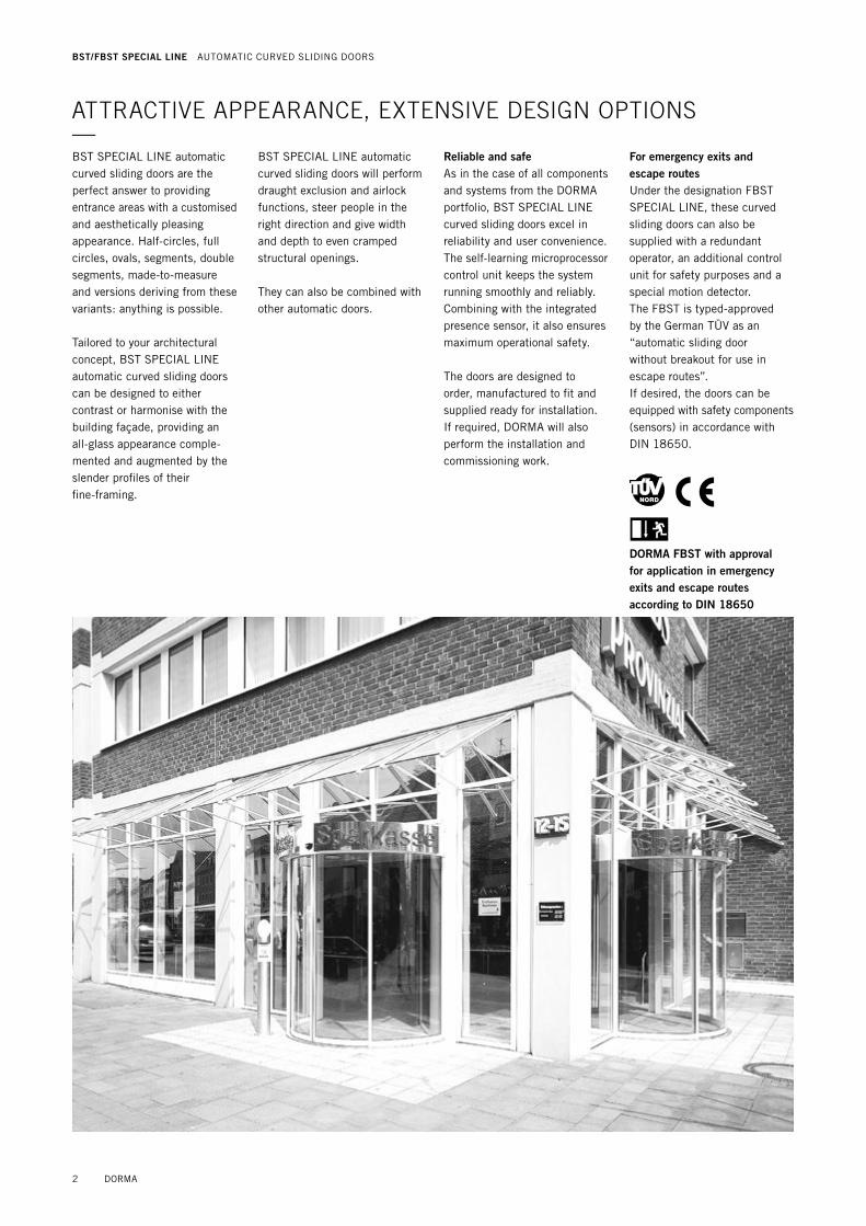
ATTRACTIVE APPEARANCE, EXTENSIVE DESIGN OPTIONS—BST SPECIAL LINE automatic curved sliding doors are the perfect answer to providing entrance areas with a customised and aesthetically pleasing appearance. Half-circles, full circles, ovals, segments, double segments, made-to-measure and versions deriving from these variants: anything is possible.
Tailored to your architectural concept, BST SPECIAL LINE automatic curved sliding doors can be designed to either contrast or harmonise with the building façade, providing an all-glass appearance comple-mented and augmented by the slender profiles of their fine-framing.
BST SPECIAL LINE automatic curved sliding doors will perform draught exclusion and airlock functions, steer people in the right direction and give width and depth to even cramped structural openings.
They can also be combined with other automatic doors.
Reliable and safeAs in the case of all components and systems from the DORMA portfolio, BST SPECIAL LINE curved sliding doors excel in reliability and user convenience. The self-learning microprocessor control unit keeps the system running smoothly and reliably. Combining with the integrated presence sensor, it also ensures maximum operational safety.
The doors are designed to order, manufactured to fit and supplied ready for installation. If required, DORMA will also perform the installation and commissioning work.
For emergency exits and escape routesUnder the designation FBST SPECIAL LINE, these curved sliding doors can also be supplied with a redundant operator, an additional control unit for safety purposes and a special motion detector.The FBST is typed-approved by the German TÜV as an “automatic sliding door without breakout for use in escape routes”.If desired, the doors can be equipped with safety com ponents (sensors) in accor dance with DIN 18650.
DORMA FBST with approval for application in emergency exits and escape routes according to DIN 18650
2 DORMA
BST/FBST SPECIAL LINE AUTOMATIC CURVED SLIDING DOORS
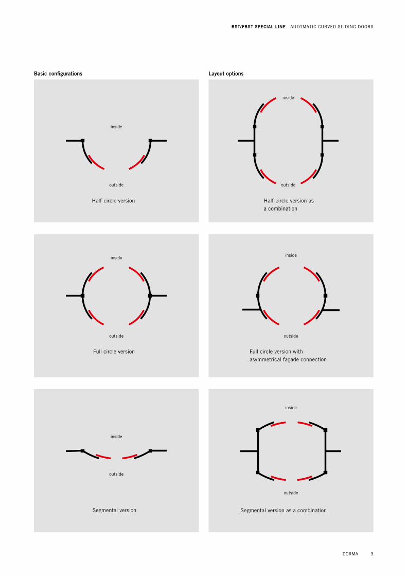
Basic configurations
Half-circle version as a combination
Half-circle version
Segmental version
Full circle version
Segmental version as a combination
Full circle version withasymmetrical façade connection
Layout options
inside
outside
inside
outside
inside
outside
inside
outside
inside
outside
inside
outside
DORMA 3
BST/FBST SPECIAL LINE AUTOMATIC CURVED SLIDING DOORS
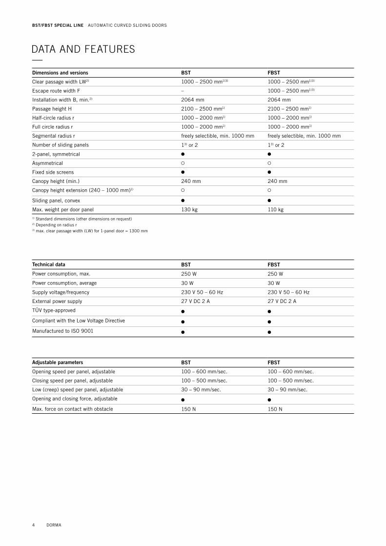
Dimensions and versions BST FBST
Clear passage width LW2) 1000 – 2500 mm1)3) 1000 – 2500 mm1)3)
Escape route width F – 1000 – 2500 mm1)3)
Installation width B, min.2) 2064 mm 2064 mm
Passage height H 2100 – 2500 mm1) 2100 – 2500 mm1)
Half-circle radius r 1000 – 2000 mm1) 1000 – 2000 mm1)
Full circle radius r 1000 – 2000 mm1) 1000 – 2000 mm1)
Segmental radius r freely selectible, min. 1000 mm freely selectible, min. 1000 mm
Number of sliding panels 13) or 2 13) or 2
2-panel, symmetrical 3 3
Asymmetrical § §
Fixed side screens 3 3
Canopy height (min.) 240 mm 240 mm
Canopy height extension (240 – 1000 mm)1) § §
Sliding panel, convex 3 3
Max. weight per door panel 130 kg 110 kg1) Standard dimensions (other dimensions on request) 2) Depending on radius r 3) max. clear passage width (LW) for 1-panel door = 1300 mm
Technical data BST FBST
Power consumption, max. 250 W 250 W
Power consumption, average 30 W 30 W
Supply voltage/frequency 230 V 50 – 60 Hz 230 V 50 – 60 Hz
External power supply 27 V DC 2 A 27 V DC 2 A
TÜV type-approved 3 3
Compliant with the Low Voltage Directive 3 3
Manufactured to ISO 9001 3 3
Adjustable parameters BST FBST
Opening speed per panel, adjustable 100 – 600 mm/sec. 100 – 600 mm/sec.
Closing speed per panel, adjustable 100 – 500 mm/sec. 100 – 500 mm/sec.
Low (creep) speed per panel, adjustable 30 – 90 mm/sec. 30 – 90 mm/sec.
Opening and closing force, adjustable 3 3
Max. force on contact with obstacle 150 N 150 N
DATA AND FEATURES—
4 DORMA
BST/FBST SPECIAL LINE AUTOMATIC CURVED SLIDING DOORS

Accessories BST FBST
Fanlight § §
Façade connection, panel board § §
Aluminium girder with aluminium cover, external
3 3
Aluminium girder 3 3
Adhesive-bonded midrails § §
Air curtain (180 and 360° design, canopy extension required)
§ §
LED-Spotlights § §
Floor mat § §
Floor guide rail
Surface-mounted floor guide without floor ring
3 3
Surface-mounted floor guide with floor ring
§ §
Flush-mounted floor guide with floor ring (Compulsory for clear passage widths (LW) beyond 1500 mm)
§ §
Accessories/Safety equipment BST FBST
Locking device
Electro-mechanical locking device § –
Electro-mechanical locking device with manual lock release
§ §
Fail-safe via emergency power supply unit
§ 3
Monitored rechargeable battery pack § 3
Intrinsically safe activator in escape direction
– 3
Motion detector, external § §
Motion detector, internal §
Emergency pushbuttons
Emergency Off function § –
Emergency Opening function – §
Program modes BST FBST
Off 3 3
Automatic 3 3
Exit Only 3 3
Permanent Open 3 3
Partial Open, Exit Only 3 3
Night-/Bank Function 3 w
Design of ceiling BST FBST
Ceiling 3 §
Operator cover § 3
Upper dust-proof ceiling 3 3
Ceiling prepared for rainproofing (by others), incl. spouts
§ –
Profiles and glazing BST FBST
Fine-frame profile system with 10 mm laminated safety glass - G
3 3
Special glazing with patterning, sand-blast effect, screen printing etc.
§ §
3 standard § optional
Operator and control unit BST FBST
Operator ES 200 ES 200 2D
Microprocessor control unit 3 3
Integrated presence sensor § §
Equipped in accordance with DIN 18650
§ §
Obstruction self-recognition 3 3
Automatic reversing cycle on obstruction contact
3 3
Complete system self-test 3 3
Connection for airlock function 3 –
Parameter adjustment capable 3 3
Self-learning 3 3
Class of protection IP 20 IP 20
Pulse expansion for cheque and code card readers or key switches
3 3
Potential-free contact 3 3
Bus-capable 3 3
Door status contact, locking device for door system
§ §
DORMA 5
BST/FBST SPECIAL LINE AUTOMATIC CURVED SLIDING DOORS
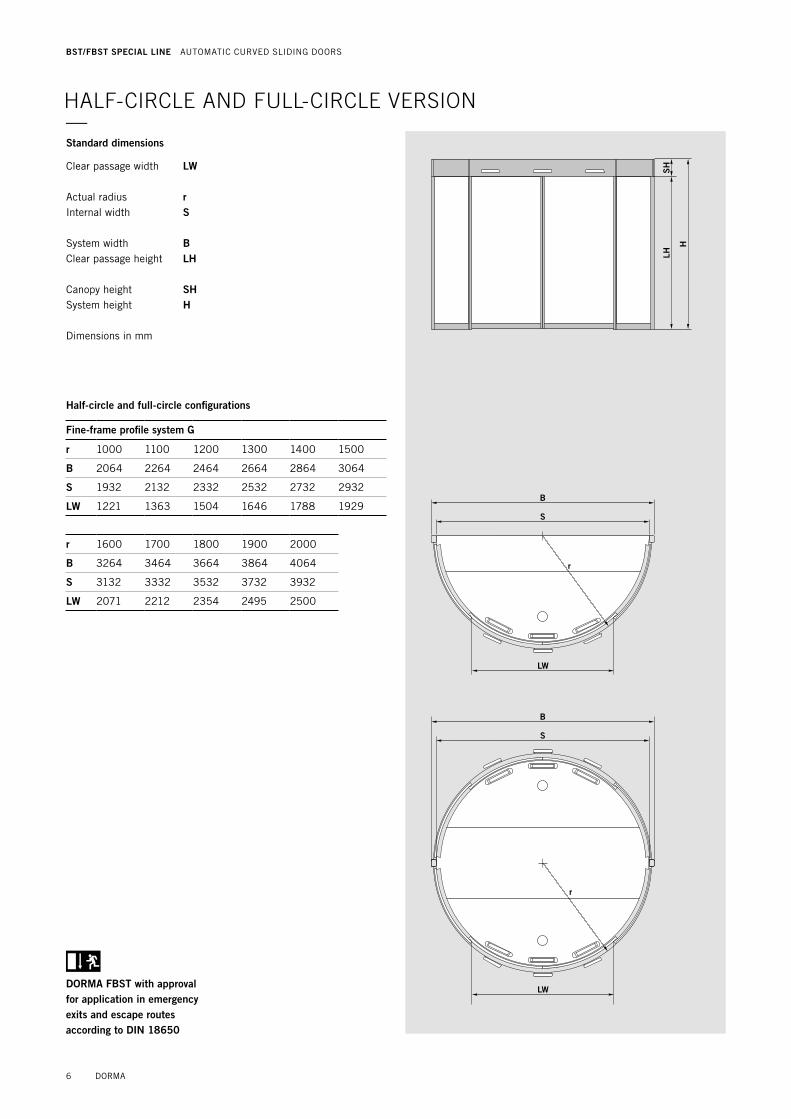
HALF-CIRCLE AND FULL-CIRCLE VERSION—
SEITE 6-1
LH
H
SH
B
S
LW
r
LW
B
S
r
LH 2
72
SH
LW
SB
S
B
Half-circle and full-circle configurations
Fine-frame profile system G
r 1000 1100 1200 1300 1400 1500
B 2064 2264 2464 2664 2864 3064
S 1932 2132 2332 2532 2732 2932
LW 1221 1363 1504 1646 1788 1929
r 1600 1700 1800 1900 2000
B 3264 3464 3664 3864 4064
S 3132 3332 3532 3732 3932
LW 2071 2212 2354 2495 2500
Standard dimensions
Clear passage width LW Actual radius r Internal width S System width B Clear passage height LH Canopy height SH System height H
Dimensions in mm
DORMA FBST with approval for application in emergency exits and escape routes according to DIN 18650
6 DORMA
BST/FBST SPECIAL LINE AUTOMATIC CURVED SLIDING DOORS

SEITE 6-1
LH
H
SH
B
S
LW
r
LW
B
S
r
LH 2
72
SH
LW
SB
S
B
SEITE 6-1
LH
H
SH
B
S
LW
r
LW
B
S
r
LH 2
72
SH
LW
SB
S
B
Aluminium girder with connection to half-circle drum wall
Aluminium girder with connection to full circle drum wall
SEITE 6-1
LH
H
SH
B
S
LW
r
LW
B
S
r
LH 2
72
SH
LW
SB
S
B
Panels with centre seals
Drum wall and sliding panel with sealing profiles
Fine-frame profile system G
SEITE 6-1
LH
H
SH
B
S
LW
r
LW
B
S
r
LH 2
72
SH
LW
SB
S
B
Norminal radius (r)
Internal radius
DORMA 7
BST/FBST SPECIAL LINE AUTOMATIC CURVED SLIDING DOORS
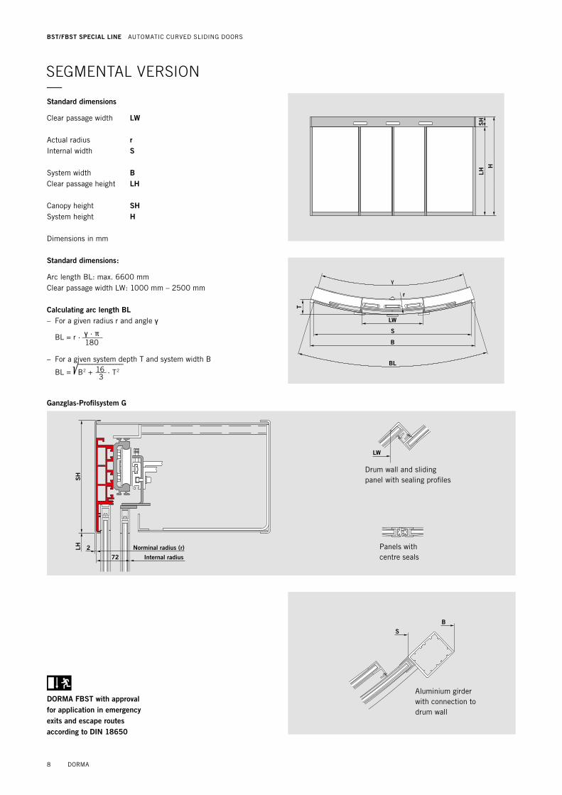
SEGMENTAL VERSION—
Standard dimensions:
Arc length BL: max. 6600 mm Clear passage width LW: 1000 mm – 2500 mm
Calculating arc length BL– For a given radius r and angle ⁄
BL = r · ⁄ · ™ 180
– For a given system depth T and system width B
BL = B2 + 16 · T2
3
m,,,,,,,,,,,,,
DORMA FBST with approval for application in emergency exits and escape routes according to DIN 18650
LHH
SH
T
LW
S
BL
⁄
B
r
LHH
SH
T
LW
S
BL
⁄
B
r
SH
LH 2
72
LW
S
B
SH
LH 2
72
LW
S
B
Aluminium girder with connection to drum wall
Panels with centre seals
Drum wall and sliding panel with sealing profiles
Ganzglas-Profilsystem G
Norminal radius (r)
Internal radius
Standard dimensions
Clear passage width LW Actual radius r Internal width S System width B Clear passage height LH Canopy height SH System height H
Dimensions in mm
8 DORMA
BST/FBST SPECIAL LINE AUTOMATIC CURVED SLIDING DOORS
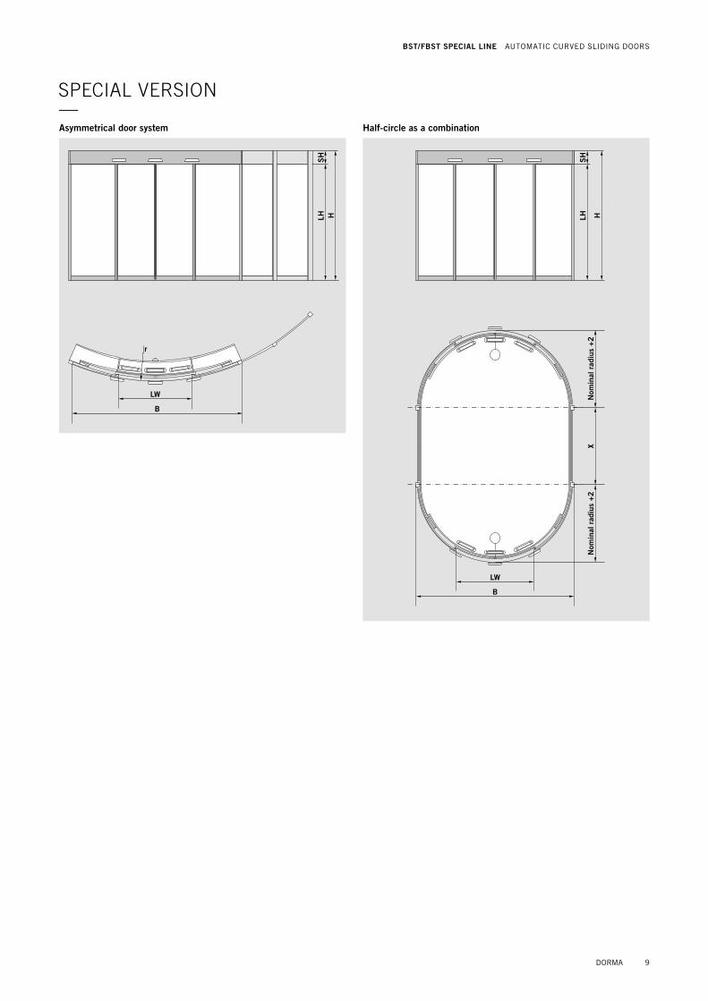
SPECIAL VERSION—
LH HS
H
B
LW
r
LW
2x LW
LW
2x LW
Asymmetrical door system Half-circle as a combination
LH H
SH
XLW
BN
omin
al r
adiu
s +
2N
omin
al r
adiu
s +
2
DORMA 9
BST/FBST SPECIAL LINE AUTOMATIC CURVED SLIDING DOORS
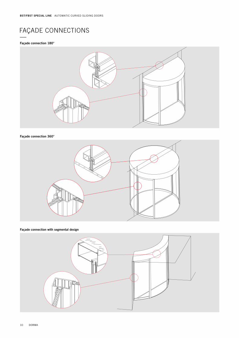
Façade connection 180°
Façade connection with segmental design
Façade connection 360°
FAÇADE CONNECTIONS—
10 DORMA
BST/FBST SPECIAL LINE AUTOMATIC CURVED SLIDING DOORS
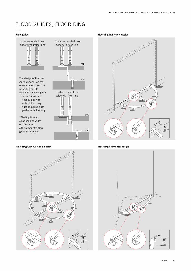
Surface-mounted floor guide without floor ring
Surface-mounted floor guide with floor ring
Flush-mounted floor guide with floor ring
The design of the floor guide depends on the opening width* and the prevailing on-site conditions and comprises– surface-mounted
floor guides with/ without floor ring
– flush-mounted floor guides with floor ring.
*Starting from a clear opening width of 1500 mm, a flush-mounted floor guide is required.
Floor guide Floor ring half-circle design
Floor ring segmental designFloor ring with full circle design
min 56
min
80
min 56
min
80 min 56
min
80
FLOOR GUIDES, FLOOR RING—
FFL
FFL
SSL
SSL
DORMA 11
BST/FBST SPECIAL LINE AUTOMATIC CURVED SLIDING DOORS

inside outside
AIR CURTAIN—
12 DORMA
BST/FBST SPECIAL LINE AUTOMATIC CURVED SLIDING DOORS
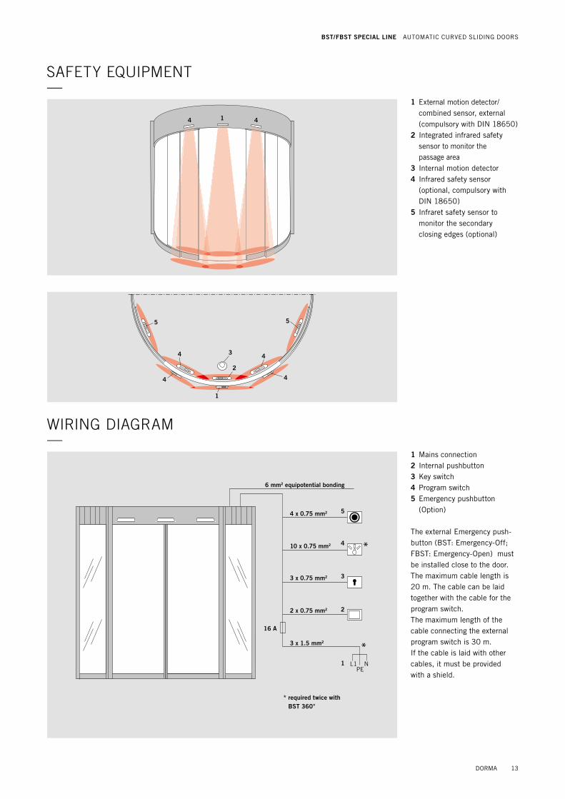
SAFETY EQUIPMENT—
WIRING DIAGRAM—
1 Mains connection2 Internal pushbutton3 Key switch4 Program switch5 Emergency pushbutton
(Option)
The external Emergency push-button (BST: Emergency-Off; FBST: Emergency-Open) must be installed close to the door. The maximum cable length is 20 m. The cable can be laid together with the cable for the program switch. The maximum length of the cable connecting the external program switch is 30 m. If the cable is laid with other cables, it must be provided with a shield.
1 External motion detector/ combined sensor, external (compulsory with DIN 18650)
2 Integrated infrared safety sensor to monitor the passage area
3 Internal motion detector4 Infrared safety sensor
(optional, compulsory with DIN 18650)
5 Infraret safety sensor to monitor the secondary closing edges (optional)
4 41
1
2
3
55
44
4 4
16 A
L1 NPE
1
2
3
4
5
*
*
6 mm2 equipotential bonding
* required twice with BST 360°
4 x 0.75 mm2
10 x 0.75 mm2
3 x 0.75 mm2
2 x 0.75 mm2
3 x 1.5 mm2
DORMA 13
BST/FBST SPECIAL LINE AUTOMATIC CURVED SLIDING DOORS
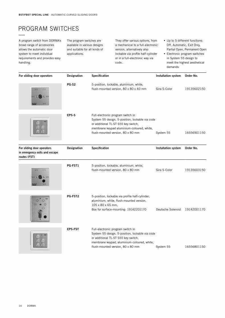
PROGRAM SWITCHES—A program switch from DORMA's broad range of accessories allows the automatic door system to meet individual requirements and provides easy handling.
The program switches are available in various designs and suitable for all kinds of applications.
They offer various options, from a mechanical to a full-electronic version, alternatively also lockable via profile half-cylinder or in a full-electronic way via code..
. Up to 5 different functions: Off, Automatic, Exit Only, Partial Open, Permanent Open . Electronic program switches in System 55 design to meet the highest aesthetical demands
For sliding door operators Designation Specification Installation system Order No.
PG-S2 5-position, lockable, aluminium, white, flush-mounted version, 80 x 80 x 40 mm Gira S-Color 19135602150
EPS-S Full-electronic program switch in System 55 design, 5-position, lockable via code or additional TL-ST S55 key switch, membrane keypad aluminium-coloured, white, flush-mounted version, 80 x 80 mm System 55 16556901150
For sliding door operators in emergency exits and escape routes (FST)
Designation Specification Installation system Order No.
PG-FST1 5-position, lockable, aluminium, white, flush-mounted version, 80 x 80 mm Gira S-Color 19135603150
PG-FST2 5-position, lockable via profile half-cylinder, aluminium, white, flush-mounted version, 105 x 80 x 65 mm, Box for surface-mounting: 19142201170 Deutsche Solenoid 19142001170
EPS-FST Full-electronic program switch in System 55 design, 5-position, lockable via code or additional TL-ST S55 key switch, membrane keypad, aluminium-coloured, white, flush-mounted version, 80 x 80 mm System 55 16556801150
14 DORMA
BST/FBST SPECIAL LINE AUTOMATIC CURVED SLIDING DOORS

PUSHBUTTON—Palm pushbutton Designation Specification Installation system Order No.
Single-pole changeover contact, single-type frame, white, flush-mounted version System 55 19144701170
Key switches Designation Specification Installation system Order No.
KT 3-1 1 NO contact with profile half-cylinder, may be replaced for any profile half-cylinder of a master key system, key only retractable in neutral position, aluminium, metal, 75 x 75 x 60 mm
KT 3-1 UP flush-mounted version 05054531332KT 3-1 AP surface-mounted version 05054631332
EMERGENCY PUSHBUTTONS—
Designation Specification Installation system Order No.
NAT Designed to interrupt the automatic movement of the door, emergency pushbutton (function: Emergency Off) for automatic door operators, manufactured to ZH 1/494 or BGR 232 and DIN 18650 and EN 16005, red knob with yellow centre insert, max. load current: 10 A at 230 V AC
NAT 1 NO contact: 1, NC contact: 1, white frame, flush-mounted version, 80 x 80 mm System 55 90400025
NAT 2no picture
Function “Emergency Opening” with green knob, NO contact: 1, NC contact: 1, max. load current: 10 A at 230 V AC, white frame, flush-mounted version, 80 x 80 mm System 55 90400035
DORMA 15
BST/FBST SPECIAL LINE AUTOMATIC CURVED SLIDING DOORS

DORMA Deutschland GmbHDORMA Platz 158256 EnnEPEtAlGERMAnyPhone +49 2333 793-0Fax +49 2333 793-4950www.dorma.com
DORMA Beschlagtechnik GmbH Donnenberger straße 2 42553 VElBERt GERMAnyPhone +49 2053 495-0 Fax +49 2053 495-100
Layo
ut S
. 7
–
DO
RM
A C
I-2
01
2 •
eng
lisch
• B
esch
lagt
echn
ik •
Sta
nd 2
8.0
3.2
01
4
DORMA_U4-Adressen_CI-2012.indd 7 26.08.14 15:44
WN
05
342
0 5
1532, 0
9/1
4, B
ST/
FBS
T, G
B, x.
XX
X. x
x/14
Sub
ject
to
chan
ge w
itho
ut n
otic
e


