University of Wollongong Research Online Faculty of Engineering and Information Sciences - Papers: Part A Faculty of Engineering and Information Sciences 2015 Stability enhancement of magnetic levitation ball system with two controlled electomagnets Hai Huang University of Wollongong, [email protected]Haiping Du University of Wollongong, [email protected]Weihua Li University of Wollongong, [email protected]Research Online is the open access institutional repository for the University of Wollongong. For further information contact the UOW Library: [email protected]Publication Details H. Huang, H. Du & W. Li, "Stability enhancement of magnetic levitation ball system with two controlled electomagnets," in Power Engineering Conference (AUPEC), 2015 Australasian Universities, 2015, pp. 1-6.
Transcript
University of WollongongResearch Online
Faculty of Engineering and Information Sciences -Papers: Part A Faculty of Engineering and Information Sciences
2015
Stability enhancement of magnetic levitation ballsystem with two controlled electomagnetsHai HuangUniversity of Wollongong, [email protected]
Research Online is the open access institutional repository for the University of Wollongong. For further information contact the UOW Library:[email protected]
Publication DetailsH. Huang, H. Du & W. Li, "Stability enhancement of magnetic levitation ball system with two controlled electomagnets," in PowerEngineering Conference (AUPEC), 2015 Australasian Universities, 2015, pp. 1-6.
Stability enhancement of magnetic levitation ball system with twocontrolled electomagnets
AbstractMagnetic levitation ball system is a highly nonlinear and unstable system. If the system is linearised at theequilibrium point, the achievable balance range of the magnetically levitated ball is very short with oneelectromagnet. This paper presents an improved magnetic levitation ball system, that contains twoelectromagnets, where one electromagnet is set above the magnetic ball for pulling, and another one is setunder the magnetic ball for pushing. In addition, this paper applies a 2-DOF (degree-of-freedom) PID(proportional-integral-derivative) controller instead of 1-DOF PID for the control of the two electromagnetsso that they can work corporately to make the magnetic ball levitate in the air. These improvements not onlyincrease the balance range of the ball, but also make the magnetic levitation ball system more stable. Theeffectiveness of the proposed system is further validated by both numerical simulations and real experiments.
DisciplinesEngineering | Science and Technology Studies
Publication DetailsH. Huang, H. Du & W. Li, "Stability enhancement of magnetic levitation ball system with two controlledelectomagnets," in Power Engineering Conference (AUPEC), 2015 Australasian Universities, 2015, pp. 1-6.
This conference paper is available at Research Online: http://ro.uow.edu.au/eispapers/4754
Because of the particular non-contact feature, the magnetic levitation system has been widely implemented and applied in many areas in the world from magnetically levitated vehicles to artworks [6]. For example, in [7], the magnetic levitation technology was used for the railway transportation system. Moreover, because there is no any mechanical contact and less heat generation, magnetic bearings were applied for blood pumps [8]. Another good application of the magnetic levitation system is the magnetic actuator [10]. The magnetic actuator can generate non-contact force to reduce the vibration transmission no matter it is high frequency vibration or low frequency vibration, so it can be well used for vibration isolation [9][10]. However, the magnetic levitation systems are quite unstable and nonlinear in the open-loop [2]. So, how to design a good structure and an effective controller is critical for the real applications of magnetic levitation systems.
The magnetic levitation ball system is a benchmark magnetic levitation system that can generate an appropriate magnetic force to make an iron ball suspend in the air by appropriately regulating the coil current [1]. This system is often used to study the system modelling and control issues so
that any newly proposed schemes can be further applied to the real applications. Magnetic levitation ball systems mainly have two kinds of structures [1]. In the first structure, an electromagnet is put over the magnetic ball to provide an attractive force to counteract the gravity of the ball [3] [4]. So this structure is simple and efficient in energy consumption [4]. However, because of the nonlinear characteristics of the electromagnet, the controllable gap between the ball and the electromagnet is very small, and as the gap increases, the system becomes more and more unstable. Another structure is that an electromagnet is set under the ball to provide a repulsive force [5]. But in order to make ball suspend stably in this case, additional electromagnets need to provide forces on a plurality of directions to bind the ball. So, three or more electromagnets have to be used in this structure. However, these forces are not in one direction, the efficiency of the system is greatly decreased. Using a suitable structure in different applications is becoming a necessary condition.
Another necessary component for the successful application of the magnetic levitation system is the controller design. In recent years, a lot of scholars studied on how to better control the magnetic levitation systems based on the linearised model or the nonlinear model. In [12] a nonlinear feedback linearizing controller has been used for magnetic levitation systems [2]. And some researchers have used robust controller like Q-parameterization theory and µ-analysis control or H∞ disturbance attenuation controller [13] [14]. In order to increase the suspension distance and achieve good tracking, other researchers consider the nonlinear models. More complex controllers are used for the control of the magnetic levitation systems, for example fuzzy logic controller, neural controllers, and fuzzy compensation based adaptive PID controller were proposed in the literature [15] [16] [18]. However most of these controllers are complex, and therefore, need high computational effort.
In this paper, a new magnetic levitation ball structure that uses two electromagnets corporately to make a magnetic ball suspend is presented. Using this structure, the distance between the ball and the electromagnets increases greatly, and as the balance range of the ball increases, some new applications can be achieved. For example, levitating disco ball can levitate at the centre of a dancing floor [19]. Furthermore, the stability of the system is increased when two forces work corporately. In
addition, a 2-DOF PID controller is applied in this paper. Compared with the 1-DOF PID controllers which have been often used before, the 2-DOF PID controller has simple structure and is more efficient [20] [21]. Simulation results show that the magnetic levitation ball system can work as expected with the proposed structure and the designed 2-DOF PID controller. Furthermore, the real experiments, where a Hilink real-time control board is used as an interface between the real magnetic levitation ball system and the Matlab/Simulink software for the implementation of the hardware-in-the-loop control, confirm the results.
This paper is organised as following. Section II contains the mathematical model of the magnetic levitation ball system. Section III is devoted to the design of the controller for the system. Section IV presents the simulation and real experiment results of the magnetic levitation ball system. Finally, the conclusion is given in Section V.
II. DYNAMIC MODELLING OF MAGNETIC LEVITATION BALL
SYSTEM
The proposed magnetic levitation ball system consists of two electromagnets that can work together to make a magnetic ball levitate. A hall-effect sensor is used for measuring the position of the magnet ball [15]. The two electromagnets, one is over the ball and another one is under the ball. The advantage of this structure is that both forces are in the same direction and the forces which are on other directions to be used for binding the ball are not needed any more.
Fig.1 shows that the ball is subjected to three forces, pulling force F1 generated by the coil L1,repulsive force F2 generated
by the coil L2,and the gravity of the ball. Because of using two same electromagnets, the resistance R1=R2, the induction L1=L2. The displacement is x2 = X – x1, where X is the distance between x1 and x2, and the control voltage is u1 = k1u2, where k1 is a positive constant. The hall-effect sensor equation, which is used to measure the position of the ball, is x1 = ce, where c is the parameter of the sensor, and e is the output of the sensor.
Fig. 1. Model of the proposed electromagnetic levitation ball system.
The summation of the two magnetic forces generated by the
electromagnets can be described as:
𝐹(𝑖, 𝑥) = 𝐹1 − 𝐹2
Then, the motion of the magnetic levitation ball is described by the following equation,
𝑚�̈� = 𝑚𝑔 − 𝐹(𝑖, 𝑥)
Where m is the mass of the magnetic ball; g is gravity constant; i is the current of the electromagnet coil current; x is the displacement between the electromagnet and the ball; and
𝐹(𝑖, 𝑥) = 𝐾𝑖2
𝑥2
where K is a constant. When the ball is at the balance point, then 𝑚�̈�=0, and,
𝑚𝑔 = 𝐾𝑖0
2
𝑥02
For linearisation purpose, Taylor formula can be used:
𝐹𝑖(𝑖0, 𝑥0) =𝛿𝐹(𝑖,𝑥)
𝛿𝑖|𝑖=𝑖0 𝑥=𝑥0
𝐹𝑥(𝑖0, 𝑥0) =𝛿𝐹(𝑖,𝑥)
𝛿𝑥|𝑖=𝑖0 𝑥=𝑥0
Then let Ki as the current stiffness parameter and Kx as the
displacement stiffness parameter:
𝐾𝑖 = 𝐹𝑖(𝑖0, 𝑥0) =2𝐾𝑖0
𝑥02
𝐾𝑥 = 𝐹𝑥(𝑖0, 𝑥0) = −2𝐾𝑖0
𝑥03
The system (2) about the equilibrium position becomes:
𝑚𝑑2𝑥
𝑑𝑡2 = 𝐾𝑖(𝑖 − 𝑖0) − 𝐾𝑥(𝑥 − 𝑥0)
The voltage-current relationships for the coils are given by:
𝑢1(𝑡) = 𝑅1𝑖1(𝑡) + 𝐿1𝑑𝑖1(𝑡)
𝑑𝑡
𝑢2(𝑡) = 𝑅2𝑖2(𝑡) + 𝐿2𝑑𝑖2(𝑡)
𝑑𝑡
Because at the balance point, the value of the di(t)/dt is very small, so i1 is approximately equal to k1i2.
Although with increasing the x, the accuracy of the equation (9) reduces, the practice proves that the method of linearisation is appropriate in many applications on the controller design. After doing the Laplace transform, (9) becomes:
x(s)𝑠2 = 2𝐾𝑖0
𝑥02 𝑖(𝑠) −
2𝐾𝑖0
𝑥03 𝑥(𝑠)
By using (4), the following system transfer function is obtained
x(s)
i(𝑠)=
−1
𝐴𝑠2−𝐵
where A = i0/2g, B = i0/x0.
If defining the input of the control plant as voltage of the amplifier Uin, the output of the system x as voltage of the output Uout (the output voltage of the sensor), the system open-loop transfer function becomes:
G(s) = 𝑈𝑜𝑢𝑡(𝑠)
𝑈𝑖𝑛(𝑠)=
𝐾𝑠𝑥(𝑠)
𝐾𝑎𝑖(𝑠)= −
𝐾𝑠
𝐾𝑎(𝐴𝑠2−𝐵)
where, Ks is the parameter of the sensor,Ka is D/A output
amplifier parameter.
III. CONTROLLER DESIGN
A feed-forward type 2-DOF PID controller is used in this study. Although 1-DOF PID controller has simple structure and less parameters to be adjusted, it cannot well control the magnetic levitation ball system, and even may cause larger overshoots and reduce the stability of the system due to the system`s highly nonlinear and unstable characteristics. Unlike 1-DOF PID controller, a feed-forward gain presented in the 2-DOF structure can be used to obtain superior plant output and control responses effectively. When the system`s order is more than two or system has time delay, 2-DOF PID controller can be more effective. It is noted that there exist other types of 2-DOF PID structures, which are effective for some specific applications. But in the proposed magnetic levitation ball system, only the feed-forward type 2-DOF PID controller is discussed.
A. Structure of the feed-forward 2-DOF PID controller
The structure of the 2-DOF PID controller for the magnetic levitation ball system is shown in Fig. 2.
Fig. 2. The structure of the 2-DOF PID controller.
In the 2-DOF PID controller, the feed-forward part is defined as
𝐺𝑞(𝑠) = 𝑞1
𝑠+ 𝑞2
where the additional gain parameters q1 and q2 help to add a zero at desired location to achieve superior responses. The feedback part is defined as
PID(𝑠) = 𝑘𝑝 +𝑘𝑖
𝑠+ 𝑘𝑑𝑠
where kp, ki, kd are the gains for the proportional, integral, and derivative terms, respectively.
The closed-loop system transfer function is
𝑥𝑜
𝑟=
𝐺𝑞(𝑠)𝐺(𝑠)
1+𝑃𝐼𝐷(𝑠)𝐺(𝑠)
The key point is to choose suitable parameters of the 2-DOF
PID controller. Firstly, mask the Gq(s) block, the system
becomes a 1-DOF PID control system. Determine the suitable
parameters of the 1-DOF PID controller, kp, ki and kd, by
using trial and error method. Then, add the Gq(s) block in the
system which is shown in Fig. 2. Set the q2 = 0 (The design is
to be carried out with the feedforward parameter q2=0). For
keeping the system`s tracking performance, set ∆xo/∆r =1 at
s=0. Then following (17) obtains
𝑞1 = 𝑘𝑖
So set the q1 by (18). Finally, increase and fine turn the q2 to get an appropriate speed of the response.
IV. SIMULATION AND EXPERIMENTAL RESULTS
The magnetic levitation ball system is implemented both in simulation and the real experimental setup to further validate the effectiveness of the proposed control strategy. The 2-DOF PID controller Simulink model is shown in Fig. 3.
Fig. 3. The Simulink model of the 2-dof PID controller.
Firstly, Let q2 =0, q1=1 to make the Simulink model of the 2-DOF PID controller become 1-DOF PID controller. Then the best parameters of the kp, ki and kd, via trial and error method, can be found. In this case, kp = 10, ki=4 and kd=0.125 are used. However from the Fig. 4, it can be seen that the step response generates a large overshoot at the beginning. It means as for a high nonlinear system, the normal 1-DOF PID controller cannot achieve a satisfactory result.
Fig. 4. Normal PID controller at step response.
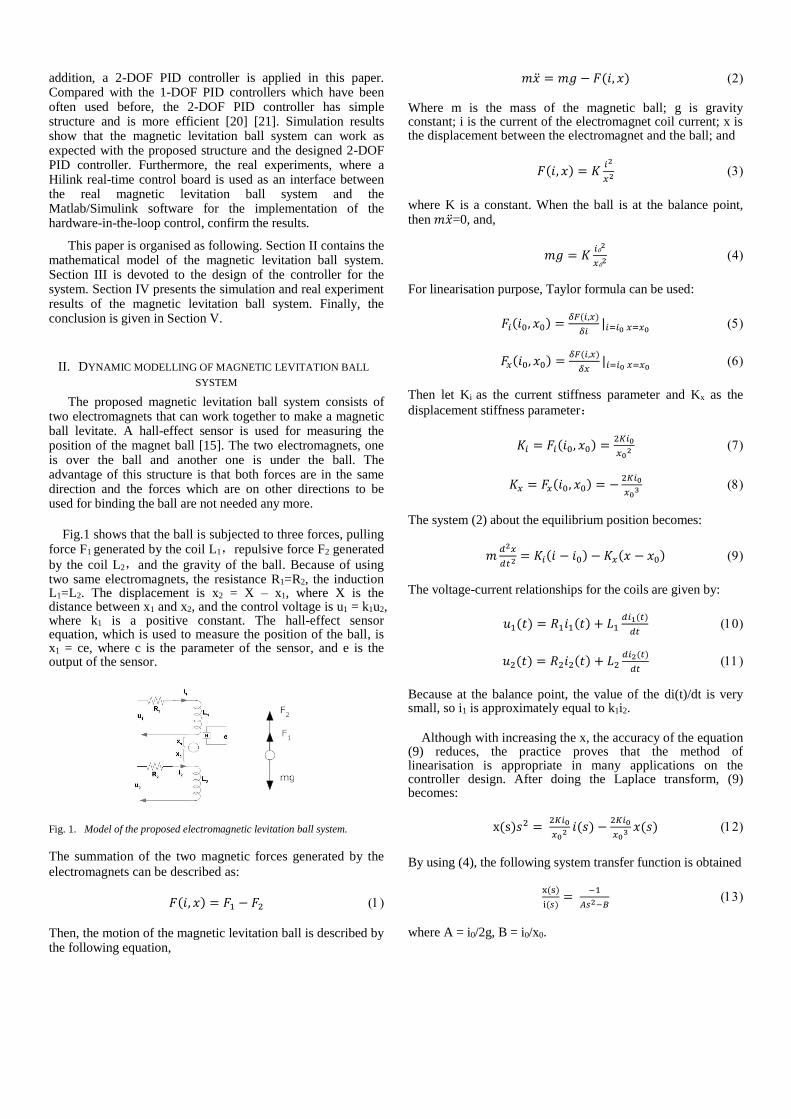
Then, try to find the parameters for 2-DOF PID controller. By
following (18) , q1=4. Fig.5 shows that, the 2-DOF PID with
q2=0 has minimal overshoot, however the rise time is the
longest.
Fig. 5. 2-DOF PID controller at step response.
Then, It is verified through simulations that with an increase in q2, the speed of the response increases and with the choice of q2=q1/4 it is found through simulations that the system’s responses are quicker. And the rise time is much shorter, but the overshoot is almost same as the curve which is q2=0. Continue to increase the system responses by setting q2=q1/1.5. The rise time of the curve is shorter than before, however the overshoot is too much lager.
Real experiment structure is shown in Fig. 6. The Hilink board [10] is used as the control board connecting the Matlab/Simulink control model and the real magnetic levitation ball system. This platform enables Matlab/Simulink simulate and control the system in real-time. Hilink Simulink Library provides the A/D and DA blocks.
Fig. 6. The experiment platform.
Fig.7 shows the Simulink model with a 2-DOF PID controller for the real magnetic levitation ball system where the Hilink blocks A0 and H0 are used to represent the analog input and output respectively. There is a reference voltage input block which is used for deciding the position of the ball. A sinusoidal signal block is used for generating sinusoidal signal and adds this signal to reference voltage signal. By comparing the difference voltage between the reference voltage and the A0 block input voltage to get the input r of the controller. Then the 2-DOF PID controller generates corresponding control voltage.
Fig. 7. Implementation of the 2-DOF PID controller.
When using one electromagnet which is connected with the
output block H0 to attract the ball, the reference voltage value
of the input is only from 3.5V to 3.6V. And if it continues to
increase the distance value (reference voltage value), the ball
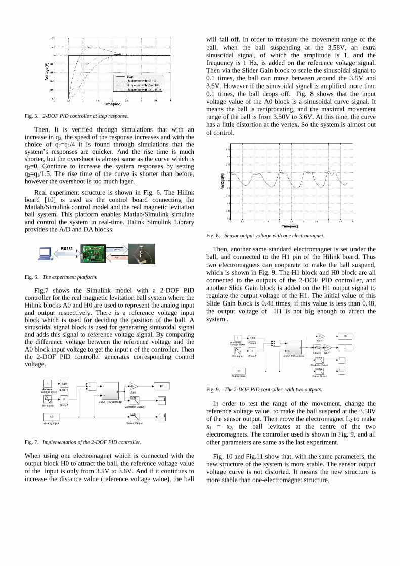
will fall off. In order to measure the movement range of the
ball, when the ball suspending at the 3.58V, an extra
sinusoidal signal, of which the amplitude is 1, and the
frequency is 1 Hz, is added on the reference voltage signal.
Then via the Slider Gain block to scale the sinusoidal signal to
0.1 times, the ball can move between around the 3.5V and
3.6V. However if the sinusoidal signal is amplified more than
0.1 times, the ball drops off. Fig. 8 shows that the input
voltage value of the A0 block is a sinusoidal curve signal. It
means the ball is reciprocating, and the maximal movement
range of the ball is from 3.50V to 3.6V. At this time, the curve
has a little distortion at the vertex. So the system is almost out
of control.
Fig. 8. Sensor output voltage with one electromagnet.
Then, another same standard electromagnet is set under the
ball, and connected to the H1 pin of the Hilink board. Thus
two electromagnets can cooperate to make the ball suspend,
which is shown in Fig. 9. The H1 block and H0 block are all
connected to the outputs of the 2-DOF PID controller, and
another Slide Gain block is added on the H1 output signal to
regulate the output voltage of the H1. The initial value of this
Slide Gain block is 0.48 times, if this value is less than 0.48,
the output voltage of H1 is not big enough to affect the
system .
Fig. 9. The 2-DOF PID controller with two outputs.
In order to test the range of the movement, change the
reference voltage value to make the ball suspend at the 3.58V
of the sensor output. Then move the electromagnet L2 to make
x1 = x2, the ball levitates at the centre of the two
electromagnets. The controller used is shown in Fig. 9, and all
other parameters are same as the last experiment.
Fig. 10 and Fig.11 show that, with the same parameters, the
new structure of the system is more stable. The sensor output
voltage curve is not distorted. It means the new structure is
more stable than one-electromagnet structure.
Fig. 10. Sensor output voltage using two electromagnets.
Fig. 11. Controller output voltage using two electromagnets.
Then continue to amplify the sinusoidal signal via
increasing the value of the Slide Gain block, the range of the
ball movement can still increase.
Fig. 12. Sensor output voltage using two electromagnets with increased gain of sinusoidal signal.
Fig. 13. Controller output voltage using two electromagnets with increased
gain of sinusoidal signal.
Fig.12 shows the output of the A0 block when the input of
the sinusoidal signal is amplified to 0.2 times. And the ball is
moving between 3.48v and 3.62v. At this time, the curve of
the sensor output voltage is distorted.
Fig. 13 shows the controller output voltage, It is also a
sinusoidal curve signal however it is shown that the system is
almost out of control.
Then, increase the value of the Slide Gain block, which is
connected to the H1 block, to 0.57 times, so that the voltage of
the H1 output is increased. The distortion of the sensor output
voltage curve disappears, which is shown in Fig. 14. And Fig.
15 shows that the controller works better than before.
Fig. 14. Sensor output voltage using two electromagnets with increased H1
output.
Fig. 15. Controller output voltage using two electromagnets with increased
H1 output.
Repeat the above steps, when the sinusoidal signal is
amplified to 0.33 times, and H1 is amplified to 0.76 times,
Fig. 16 and Fig. 17 show the sensor output voltage curve and
controller output voltage curve, which mean the movement
range of the ball is from 3.46V to 3.64V, and the system is
still controlled well. So using new structure can effectively
increase the range of the ball`s movement and the system is
more stable.
Fig. 16. Sensor output voltage using two electromagnets with increased
movement range.
Fig. 17. Controller output voltage using two electromagnets with increased movement range.
V. CONCLUSION
A two-electromagnet magnetic levitation ball system is proposed in this paper and a 2-DOF PID controller is applied. This new structure of the magnetic levitation ball system shows better performance than previous magnetic levitation ball systems. From the simulation and real experiment results it can be seen that using two electromagnets can make a ball levitate and can not only increase the balance range of the ball, but also make the system more stable.
A 2-DOF PID controller has also been proposed in this paper for controlling the real magnetic levitation ball system. Although it has been noted that the conventional PID controller depends on the system parameters, the superior robustness of the 2-DOF configuration can be achieved in real-time by properly setting the feed-forward term.
Increasing the balance range of the ball means the magnetic levitation ball system can apply in more fields. At the same time, a simple and effective controller, like 2-DOF PID controller, is more economical and occupies less computational resources, so there are more advantages in practical application than other controllers.
REFERENCES
[1] Wong, T. H. "Design of a magnetic levitation control system-an undergraduate project." IEEE Transactions on Education 29.4 (1986): 196-200.
[2] El Hajjaji, Ahmed, and M. Ouladsine. "Modeling and nonlinear control of magnetic levitation systems." IEEE Transactions on Industrial Electronics 48.4 (2001): 831-838.
[3] 松村文夫, and 山田外史. "A Control Method of Suspension Control System by Magnetic Attractive Force." 電気学会論文誌 . B 94.11 (1974): 567-574.
[4] Jayawant, B. V., and D. P. Rea. "New electromagnetic suspension and its stabilisation." Electrical Engineers, Proceedings of the Institution of 115.4 (1968): 549-554.
[5] Laithwaite, E. R. "Electromagnetic levitation." Electrical Engineers, Proceedings of the Institution of 112.12 (1965): 2361-2375.
[6] Al-Muthairi, N. F., and M. Zribi. "Sliding mode control of a magnetic levitation system." Mathematical Problems in Engineering 2004.2 (2004): 93-107.
[7] Lee, Hyung-Woo, Ki-Chan Kim, and Ju Lee. "Review of maglev train technologies." Magnetics, IEEE Transactions on 42.7 (2006): 1917-1925.
[8] Hoshi, Hideo, Tadahiko Shinshi, and Setsuo Takatani. "Third ‐generation Blood Pumps With Mechanical Noncontact Magnetic Bearings." Artificial organs 30.5 (2006): 324-338.
[9] Song, Chun-sheng, et al. "Dynamic modeling of magnetic suspension isolator using artificial neural network: a modified genetic approach." Journal of Vibration and Control 19.6 (2013): 847-856.
[10] Lee, Hyung-Woo, Ki-Chan Kim, and Ju Lee. "Review of maglev train technologies." Magnetics, IEEE Transactions on 42.7 (2006): 1917-1925.
[11] Joo, SungJun, and Jin H. Seo. "Design and analysis of the nonlinear feedback linearizing control for an electromagnetic suspension system." Control Systems Technology, IEEE Transactions on 5.1 (1996): 135-144.
[12] Zhao, Feng, Shiou C. Loh, and Jeff A. May. "Phase-space nonlinear control toolbox: The maglev experience." Hybrid Systems V. Springer Berlin Heidelberg, 1999. 429-444.
[13] Mohamed, A. M., et al. "Q-parametrization//spl mu/-control of an electromagnetic suspension system." Control Applications, 1997., Proceedings of the 1997 IEEE International Conference on. IEEE, 1997.
[14] Fujita, M. A. S. A. Y. U. K. I., Fumio Matsumura, and Kenko Uchida. "Experiments on the H∞ disturbance attenuation control of a magnetic suspension system." Decision and Control, 1990., Proceedings of the 29th IEEE Conference on. IEEE, 1990 .
[15] Salim, Tania Tariq, and Vedat Mehmet Karsli. "Control of Single Axis Magnetic Levitation System Using Fuzzy Logic Control." International Journal of Advanced Computer Science and Applications 4.11 (2013).
[16] Lairi, Mostafa, and Gerard Bloch. "A neural network with minimal structure for maglev system modeling and control." Intelligent Control/Intelligent Systems and Semiotics, 1999. Proceedings of the 1999 IEEE International Symposium on. IEEE, 1999 .
[17] Ghosh, Arun, et al. "Design and implementation of a 2-DOF PID compensation for magnetic levitation systems." ISA transactions 53.4 (2014): 1216-1222.
[18] Lin, Chih-Min, Chih-Min Lin, and Chun-Wen Chen. "SoPC-based adaptive PID control system design for magnetic levitation system." Systems Journal, IEEE 5.2 (2011): 278-287.
[19] Gibbs, W. W. "Antigravity glitter build a levitating disco-ball night-light; bell-bottom pants optional." Spectrum, IEEE 51.8 (2014): 23-25.
[20] WANG, Weijie, et al. "Two-degrees-of-freedom PID controller tuning method [J]." Journal of Tsinghua University (Science and Technology) 11 (2008): 020.
[21] Gorez, Raymond. "New design relations for 2-DOF PID-like control systems." Automatica 39.5 (2003): 901-908