20
Stainless Steel Diaphragm Valves The innovative line of products for future-oriented technologies in the life science, biotechnology, cosmetic and food industries

Stainless Steel Diaphragm Valves
The innovative line of products forfuture-oriented technologies in the life science,biotechnology, cosmetic and food industries

2
Take advantage of Georg Fischer’s materials andapplications know-how for your systems
Quality already begins in the developmentphase when production conceptsand possible risks and consequencesare discussed.
That is why we suggest taking advantageof Georg Fischer‘s materials andapplications know-how at an earlystage in the design of your system.Complex piping systems are ourspeciality.
3
Take advantage of Georg Fischer’s materials andapplications know-how for your systems
4
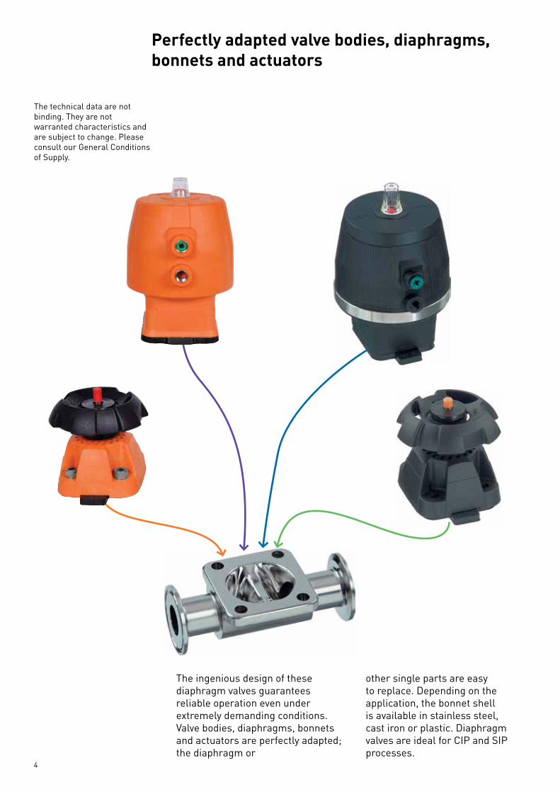
Perfectly adapted valve bodies, diaphragms,bonnets and actuators
The technical data are notbinding. They are notwarranted characteristics andare subject to change. Pleaseconsult our General Conditionsof Supply.
The ingenious design of these diaphragm valves guarantees reliable operation even under extremely demanding conditions. Valve bodies, diaphragms, bonnets and actuators are perfectly adapted; the diaphragm or
other single parts are easy to replace. Depending on the application, the bonnet shell is available in stainless steel, cast iron or plastic. Diaphragm valves are ideal for CIP and SIP processes.

5
Reliable control for demanding processes
Stainless steel diaphragm valve, Page 6Hot Water Sanitization manually operated
Stainless steel diaphragm valve, Steam Page 7Sanitization manually operated
Stainless steel diaphragm valve, Hot Page8 Water Sanitization Pneumatically actuated
Stainless steel diaphragm valve, Steam Page 9-15Sanitization pneumatically actuated
Valve bodies in stainless steel Page 16-17
Multi-port valves in stainless steel Page 18
Diaphragms Page 19
6
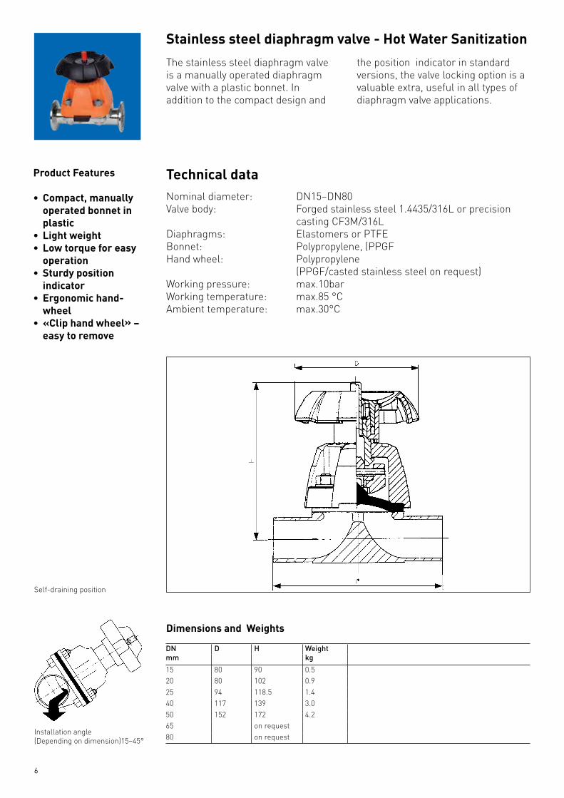
The stainless steel diaphragm valve is a manually operated diaphragm valve with a plastic bonnet. In addition to the compact design and
the position indicator in standard versions, the valve locking option is a valuable extra, useful in all types of diaphragm valve applications.
Product Features
• Compact,manuallyoperated bonnet in plastic
• Lightweight• Lowtorqueforeasy
operation• Sturdyposition
indicator• Ergonomichand- wheel• «Cliphandwheel» – easy to remove
Technical dataNominal diameter: DN15–DN80Valve body: Forged stainless steel 1.4435/316L or precision
casting CF3M/316LDiaphragms: Elastomers or PTFEBonnet: Polypropylene, (PPGFHand wheel: Polypropylene (PPGF/casted stainless steel on request)Working pressure: max.10bar Working temperature: max.85 °C Ambient temperature: max.30°C
Stainlesssteeldiaphragmvalve-HotWaterSanitization
Self-draining position
Installation angle(Depending on dimension)15–45°
DimensionsandWeights
DNmm
D H Weightkg
15 80 90 0.520 80 102 0.925 94 118.5 1.440 117 139 3.050 152 172 4.265 on request80 on request

7
The ST 195-MA stainless steel diaphragm valve is a manually operated diaphragm valve with a plastic bonnet. In addition to the compact design and the position indicator in standard versions,
the valve locking option is a valuable extra, useful in all types of diaphragm valve applications.
Product Features
• Compact,manuallyoperated bonnet in plastic
• Lightweight• Lowtorqueforeasy
operation• Sturdyposition
indicator• Ergonomichand-
wheel• «Cliphandwheel»-
easy to remove• Accessory:locking
set to lock the valve • Variableflow
direction and installation position
Technical dataNominal diameter: DN15-DN80Valve body: Forged stainless steel 1.4435/316L or precision casting
CF3M/316LDiaphragms: Elastomers or PTFEBonnet: Polypropylene, fiberglass reinforced (PP-GF 30)Hand wheel: Polypropylene (PPS/casted stainless steel on request)Working pressure: max. 10 barWorking temperature: max. 130 °C
StainlesssteeldiaphragmvalveSteamSanitization
Description
Self-draining position
Installation angle(Depending on dimension)15–45°
DimensionsandWeights
DNmm
D H Weightkg
15 80 90 0.520 80 102 0.925 94 118.5 1.440 117 139 3.050 152 172 4.265 on request80 on request

8
This compact diaphragm valve is low- maintenance, has a pneumatic actuator in plastic,and is available in the fail safe to open,fail safe to close and double acting modes of operation. The pneumatic actuators are available in sizes 025 - 10 bar
both sides / 028 - 10 bar at one side. The 028, which is dimensionally
reduced to a minimum,is especially suited to applications where space is limited. A wide range of accessories, such as electrical feedback unit, positioner or stroke limiter, allow optimal adaptation to all types of control tasks.* ASI interface can be given.
Product Features
• Compact,pneumaticactuator in plastic
• Lightweight• Failsafetoopen,
fail safe to close or double acting modes of operation
• Positionindicatorisstandard
• Lowmaintenance• Wideselectionofaccessories:electrical feedback unit, stroke limiter and positioner
• Variableflowdirection and installation position
• Autoclavable
Technical dataNominal diameter: DN15–DN80Valve body: Forged stainless steel 1.4435/316L or preci-
sion casting CF3M/316L Diaphragms: Elastomers or PTFE Actuator housing DN15–DN50: CoPAGFActuator housing DN65/DN80: PP-GF Working pressure: max.10 bar (025 - 10 / 028 - 10)Working temperature: max.85°C Control medium: Compressed air (oil-free)/neutral, non-ag-
gressive gases, max.60°CMax. permissible 6 bar for FC(fail safe spring to control pressure: close) mode, 5 bar for FO (fail safe spring to open) and DA
(double acting) modes
Valvedesign(DN15–DN50)1. Optical position indicator2. All-plastic housing are PPGF and
housing bottom of stainless steel3. Preloaded spring sets
4. Lifting spindle assembly of stainless steel
5. CoPA pistons6. Connection for control air7. Diaphragm8. Stainless steel valve body
Stainlesssteeldiaphragmvalve-HotWaterSanitization
Failsafespringtoclose(FC) Failsafespringtoopen(FO) Doubleacting(DA)

9
This compact diaphragm valve is low- maintenance, has a pneumatic actuator in plastic,and is available in the fail safe to open,fail safe to close and double acting modes of operation.The pneumatic actuators are available in size 025 or 028.The 028, which is dimensionally reduced to a minimum,is especially suited to
applications where space is limited. A wide range of accessories, such as electrical feedback unit, positioner or stroke limiter, allow optimal adaptation to all types of control tasks.* ASI interface can be given.
Product Features
• Compact,pneumaticactuator in plastic
• Lightweight• Failsafetoopen,
fail safe to close or double acting modes of operation
• Positionindicatorisstandard
• Lowmaintenance• Wideselectionofaccessories:electrical feedback unit, stroke limiter and positioner
• Variableflowdirection and installation position
• Autoclavable
Technical dataNominal diameter: DN15–DN80Valve body: Forged stainless steel 1.4435/316L or
precision casting CF3M/316L Diaphragms: Elastomers or PTFE Actuator housing DN15–DN50: CoPAGFActuator housing DN65/DN80: PP-GF Working pressure: max.10 bar (025 - 10 / 028 - 10)Working temperature: max.150°C for actuator housing in CoPA max.130°C for actuator housing in PPControl medium: Compressed air (oil-free)/neutral, non-
aggressive gases, max.60°CMax. permissible 6 bar for FC(fail safe spring to control pressure: close) mode, 5 bar for FO (fail safe spring to open) and DA
(double acting) modes
Valvedesign(DN15–DN50)1. Optical position indicator2. All-plastic housing of CoPA or
housing top of CoPAGF and housing bottom of stainless steel
3. Preloaded spring sets
4. Lifting spindle assembly of stainless steel
5. CoPA pistons6. Connection for control air7. Diaphragm8. Stainless steel valve body
Failsafespringtoclose(FC) Failsafespringtoopen(FO) Doubleacting(DA)
StainlesssteeldiaphragmvalveSteamSanitizied

10
Dimensions/Weights,PerformanceDiagrams,DN15–DN50
Mode: Fail safe spring to close (FC)Control pressure: max. 6 barDiaphragms: ElastomersSize: 028
DimensionsandWeights
DimensionsforendconnectionsaccordingtoASMEBPEconnectiontypeBodywithV-band(Hygienic)ClampConnector(ReferFigure3)ConnectionSize FlangeOD Pipe ID FacetoFaceLength Max.ValveHeight
fromPipeCenterOutsideDiameterof
ActuatorA B C D E
(mm) (mm) (mm) (mm) (mm)½” Mini 25.00 9.40 95.5 111.1 68.0½” Regular 25.00 9.40 109.5 114.6 68.0¾" 50.40 15.75 109.5 117.7 68.01" 50.40 22.10 133.5 161.4 96.01½" 50.40 34.80 156.5 234.3 151.02" 63.90 47.50 156.5 241.1 151.02½” 77.40 60.20 179.5 267.8 180.03" 90.90 72.90 179.5 273.7 180.0
BodywithV-band(Hygienic)ClampConnector(ReferFigure4)ConnectionSize PipeOD Pipe ID FacetoFaceLength Max.ValveHeight
fromPipeCenterOutsideDiameterof
Actuator
A B C D E
(mm) (mm) (mm) (mm) (mm)
½” Mini 12.70 9.40 70.0 111.1 68.0
½” Regular 12.70 9.40 84.0 114.6 68.0
¾” 19.05 15.75 84.0 117.7 68.0
1" 25.40 22.10 108.0 161.4 96.0
1½” 38.10 34.80 131.0 234.3 151.0
2" 50.80 47.50 131.0 241.1 151.0
2½” 63.50 60.20 154.0 267.8 180.0
3" 76.20 72.90 154.0 273.7 180.0
Notes:1. For V-band (Hygienic) clamp connections, clamp connector will be welded to the valve body with butt-weld end. Internal finish will be provided as
per customer’s request.2. Dimensions and tolerances for end connection and face-to-face length are as per ASME BPE.3. All other dimensions are approximate and subject to change without prior notice.

11
Dimensions/Weights,PerformanceDiagrams,
Mode: Fail safe spring to open, double acting (FO,DA)Control pressure: max. 5 barDiaphragms: all materialsSize: 025
DimensionsandWeights
Failsafespringtoopen/doubleacting(FO/DA)DN D D1 H H1 H2 H3 H41) H5 H61) H7 Ha L* L1 Lift Weightmm mm G mm mm mm mm mm mm mm mm mm mm mm mm kg15 (EPDM) 67 1/8" 98 58.5 24 22.5 46 100 155 41 .5 73.5 60 8 3.215 (PTFE) 94 1/8" 125 68.5 25 22.5 46 100 155 54 86 60 6 3.220 94 1/8" 127 70.5 25 22.5 46 100 155 54 86 60 10 3.425 94 1/8" 141 84.5 25 22.5 46 100 155 54 86 60 12 3.632 116 1/8" 167 97 26 35.5 65 100 160 65 97 60 14 4.840 145 ¼" 198 107.5 36 35.5 65 100 170 81 113 60 18 5.650 145 ¼" 216 125.5 36 35.5 65 100 170 81 113 60 22 6.6
1) = with stroke limiter / manual override *L = for valve bodies see pages 17-18
Control/WorkingPressureDiagramsFailsafespringtoopen/doubleacting(FO/DA)withEPDMdiaphragm withPTFEdiaphragm
MaximumworkingpressureDN Diaphragms
EPDM PTFEmm 15 10 10/9 10 10/920 10 10/9 10 10/925 10 10/9 10 10/932 10 10/9 10 10/940 10 10/9 10 10/950 10 10/9 10 10/9
Working pressure on one side ( )Working pressure on both sides ( )
12
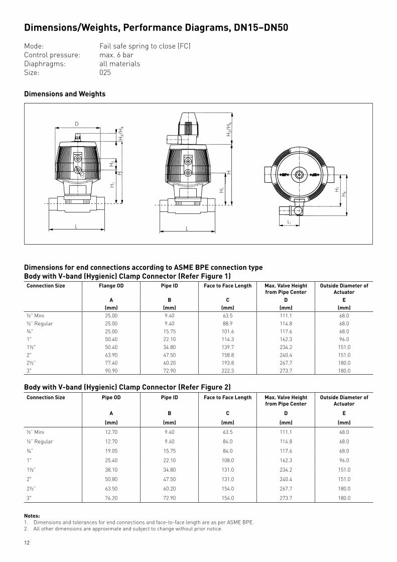
Dimensions/Weights,PerformanceDiagrams,DN15–DN50
Mode: Fail safe spring to close (FC)Control pressure: max. 6 barDiaphragms: all materialsSize: 025
DimensionsandWeights
DimensionsforendconnectionsaccordingtoASMEBPEconnectiontypeBodywithV-band(Hygienic)ClampConnector(ReferFigure1)ConnectionSize FlangeOD Pipe ID FacetoFaceLength Max.ValveHeight
fromPipeCenterOutsideDiameterof
ActuatorA B C D E
(mm) (mm) (mm) (mm) (mm)½” Mini 25.00 9.40 63.5 111.1 68.0½” Regular 25.00 9.40 88.9 114.8 68.0¾" 25.00 15.75 101.6 117.6 68.01" 50.40 22.10 114.3 162.3 96.01½" 50.40 34.80 139.7 234.2 151.02" 63.90 47.50 158.8 240.4 151.02½” 77.40 60.20 193.8 267.7 180.03" 90.90 72.90 222.3 273.7 180.0
BodywithV-band(Hygienic)ClampConnector(ReferFigure2)ConnectionSize PipeOD Pipe ID FacetoFaceLength Max.ValveHeight
fromPipeCenterOutsideDiameterof
Actuator
A B C D E
(mm) (mm) (mm) (mm) (mm)
½” Mini 12.70 9.40 63.5 111.1 68.0
½” Regular 12.70 9.40 84.0 114.8 68.0
¾” 19.05 15.75 84.0 117.6 68.0
1" 25.40 22.10 108.0 162.3 96.0
1½” 38.10 34.80 131.0 234.2 151.0
2" 50.80 47.50 131.0 240.4 151.0
2½” 63.50 60.20 154.0 267.7 180.0
3" 76.20 72.90 154.0 273.7 180.0
Notes:1. Dimensions and tolerances for end connections and face-to-face length are as per ASME BPE.2. All other dimensions are approximate and subject to change without prior notice.
13
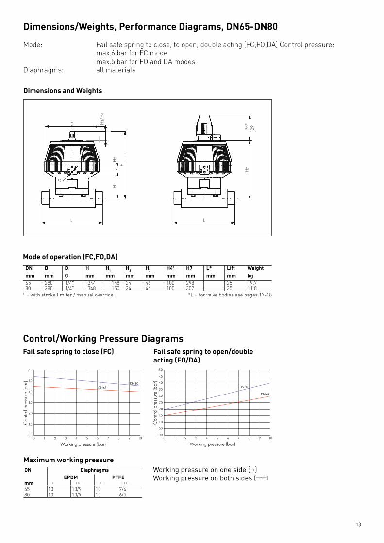
Dimensions/Weights,PerformanceDiagrams,DN65-DN80
Mode: Fail safe spring to close, to open, double acting (FC,FO,DA) Control pressure: max.6 bar for FC mode max.5 bar for FO and DA modesDiaphragms: all materials
DimensionsandWeights
Control/WorkingPressureDiagramsFailsafespringtoclose(FC) Failsafespringtoopen/double
acting(FO/DA)
MaximumworkingpressureDN Diaphragms
EPDM PTFEmm 65 10 10/9 10 7/680 10 10/9 10 6/5
Working pressure on one side ( )Working pressure on both sides ( )
Modeofoperation(FC,FO,DA)DN D D1 H H1 H2 H3 H41) H7 L* Lift Weightmm mm G mm mm mm mm mm mm mm mm kg65 280 1/4" 344 148 24 46 100 298 25 9.780 280 1/4" 348 150 24 46 100 302 35 11.8
1) = with stroke limiter / manual override *L = for valve bodies see pages 17-18

14
Accessoriesforpneumaticactuators,DN15-DN50
ElectricalFeedbackUnit,ER52
Type Type of switch max.switch.capacity Code
ER 52–1 Microswitch AG,Ni 250V~/6A 199190305
ER 52–2 Microswitchwith gold contact Au 4–30V=/1–100mA 199190306
ER 52–3 Inductive switch NPN 4.75–30V=/0.1A 199190307
ER 52–4 Inductive switch PNP 4.75–30V=/0.1A 199190308
ER 52–5 Inductive switch Namur 8V= 199190309
CompleteadaptorkitThe complete adaptor kit must be used if the valve with stroke limiter/manual over ride is combined with the electrical feedback unit ER52.Dimension ModeFC,FO,DA
Size028ModeFCSize025
DN 15 199190387 199190387DN 20 199190387 199190387DN 25 199190387 199190388DN 32 199190388 199190389DN 40 199190389 199190389DN 50 199190389 199190389
Strokelimiter/ManualoverrideDimension ModeFC,FO,DA
Size028ModeFCSize025
DN 15 199190381(EPDM)199190382(PTFE) 199190382
DN 20 199190382 199190382DN 25 199190382 199190383DN 32 199190383 199190384DN 40 199190384 199190385DN 50 199190384 199190385
Electricpneumaticpositioner(forsteamsanitisationactuators)Echardt/Sipart
Dimension Servicevoltage CodeEckhardtSRI986 single acting 199190348EckhardtSRI986 double acting 199190349
Kit 199190350
Electricpneumaticpositioner(forhotsanitisationactuators)DSR500
Discreption Servicevoltage CodePositioner DSR 500-1 single acting-FC- 24 v/dc 199190001Positioner feedback card 4-20 ma feedback 199190575
15
AdaptorplateNAMURDimension ModeFC,FO,DA
Size028ModeFCSize025
DN 15 199190378 199190378DN 20 199190378 199190378DN 25 199190378 199190378DN 32 199190378 199190379DN 40 199190379 199190379DN 50 199190379 199190379
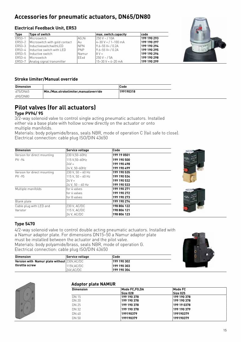
Accessoriesforpneumaticactuators,DN65/DN80
ElectricalFeedbackUnit,ER53Type Type of switch max.switch.capacity codeER53–1 Microswitch AG,Ni 250 V ~ / 10A 199190293ER53–2 Microswitch with gold contact Au 4–30 V = / 1–100 mA 199190297ER53–3 InductiveswitchwithLED NPN 9.6–55 V= / 0.2A 199190294ER53–4 Inductive switch with LED PNP 9.6–55 V= / 0.2A 199190295ER53–5 Inductive switch Namur 8 V = 199190296ER53–6 Microswitch EExd 250 V ~ / 5A 199190298ER53–7 Analog signal transmitter 15–30 V = 4–20 mA 199190299
Strokelimiter/ManualoverrideDimension Coded75/DN65 Min./Max.strokelimiter,manualoverride 199190318d90/DN80
Dimension Servicevoltage CodeVersion for direct mounting 230 V,50–60Hz 199190501PV -94 115 V,50–60Hz 199190500
24V = 19919049824 V, 50–60Hz 199190499
Version for direct mounting 230 V, 50 – 60 Hz 199190535PV -95 115 V, 50 – 60 Hz 199190534
24 V = 19919053224 V, 50 – 60 Hz 199190533
Multiple manifolds for 4 valves 199190271for 6 valves 199190272for 8 valves 199190273
Blank plate 199190274Cable plug with LED and 230 V, AC/DC 198806122Varistor 115 V, AC/DC 198806121
24 V, AC/DC 198806123
Pilotvalves(forallactuators)TypePV94/953/2-way solenoid valve to control single acting pneumatic actuators. Installed either via a base plate with hollow screw directly on the actuator or ontomultiple manifolds.Materials: body polyamide/brass, seals NBR, mode of operation C (fail safe to close).Electrical connection: cable plug ISO/DIN 43650
Type54704/2-way solenoid valve to control double acting pneumatic actuators. Installed with a Namur adaptor plate. For dimensions DN15–50 a Namur adaptor platemust be installed between the actuator and the pilot valve.Materials: body polyamide/brass, seals NBR, mode of operation G. Electrical connection: cable plug ISO/DIN 43650Dimension Servicevoltage CodeVersionwithNamurplatewithoutthrottle screw
230V,AC/DC 199190302115V,AC/DC 19919030324V,AC/DC 199190304
16
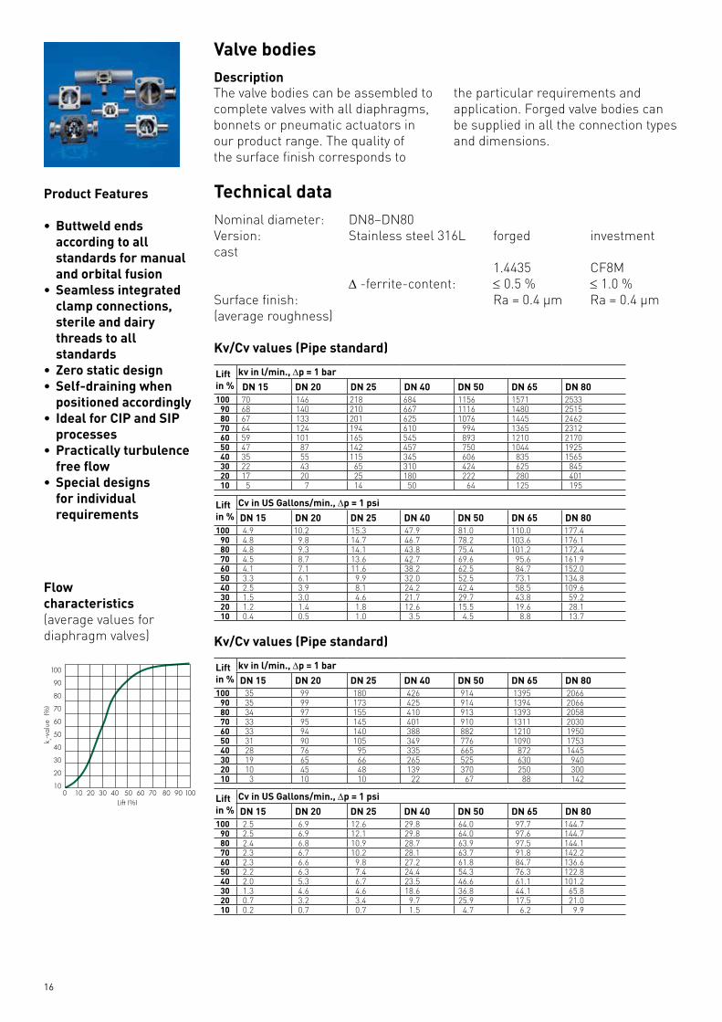
ValvebodiesDescription
Product Features
• Buttweldendsaccording to all standards for manual and orbital fusion
• Seamlessintegratedclamp connections, sterile and dairy threads to all standards
•Zerostaticdesign•Self-drainingwhen
positioned accordingly•IdealforCIPandSIP
processes•Practicallyturbulencefreeflow
•Specialdesignsfor individual requirements
Technical dataNominal diameter: DN8–DN80Version: Stainless steel 316L forged investment cast 1.4435 CF8M ∆ -ferrite-content: ≤ 0.5 % ≤ 1.0 %Surface finish: Ra = 0.4 μm Ra = 0.4 μm(average roughness)
Kv/Cvvalues(Pipestandard)
Liftin %
kvinl/min.,∆p=1barDN15 DN20 DN25 DN40 DN50 DN65 DN80
100 70 146 218 684 1156 1571 253390 68 140 210 667 1116 1480 251580 67 133 201 625 1076 1445 246270 64 124 194 610 994 1365 231260 59 101 165 545 893 1210 217050 47 87 142 457 750 1044 192540 35 55 115 345 606 835 156530 22 43 65 310 424 625 84520 17 20 25 180 222 280 40110 5 7 14 50 64 125 195
Liftin %
CvinUSGallons/min.,∆p=1psiDN15 DN20 DN25 DN40 DN50 DN65 DN80
100 4.9 10.2 15.3 47.9 81.0 110.0 177.490 4.8 9.8 14.7 46.7 78.2 103.6 176.180 4.8 9.3 14.1 43.8 75.4 101.2 172.470 4.5 8.7 13.6 42.7 69.6 95.6 161.960 4.1 7.1 11.6 38.2 62.5 84.7 152.050 3.3 6.1 9.9 32.0 52.5 73.1 134.840 2.5 3.9 8.1 24.2 42.4 58.5 109.630 1.5 3.0 4.6 21.7 29.7 43.8 59.220 1.2 1.4 1.8 12.6 15.5 19.6 28.110 0.4 0.5 1.0 3.5 4.5 8.8 13.7
Kv/Cvvalues(Pipestandard)
Liftin %
kvinl/min.,∆p=1barDN15 DN20 DN25 DN40 DN50 DN65 DN80
100 35 99 180 426 914 1395 206690 35 99 173 425 914 1394 206680 34 97 155 410 913 1393 205870 33 95 145 401 910 1311 203060 33 94 140 388 882 1210 195050 31 90 105 349 776 1090 175340 28 76 95 335 665 872 144530 19 65 66 265 525 630 94020 10 45 48 139 370 250 30010 3 10 10 22 67 88 142
Liftin %
CvinUSGallons/min.,∆p=1psiDN15 DN20 DN25 DN40 DN50 DN65 DN80
100 2.5 6.9 12.6 29.8 64.0 97.7 144.790 2.5 6.9 12.1 29.8 64.0 97.6 144.780 2.4 6.8 10.9 28.7 63.9 97.5 144.170 2.3 6.7 10.2 28.1 63.7 91.8 142.260 2.3 6.6 9.8 27.2 61.8 84.7 136.650 2.2 6.3 7.4 24.4 54.3 76.3 122.840 2.0 5.3 6.7 23.5 46.6 61.1 101.230 1.3 4.6 4.6 18.6 36.8 44.1 65.820 0.7 3.2 3.4 9.7 25.9 17.5 21.010 0.2 0.7 0.7 1.5 4.7 6.2 9.9
The valve bodies can be assembled tocomplete valves with all diaphragms,bonnets or pneumatic actuators in our product range. The quality of the surface finish corresponds to
the particular requirements and application. Forged valve bodies can be supplied in all the connection types and dimensions.
Flowcharacteristics(average values fordiaphragm valves)

17
ValvebodiesDescription
Dimensions
Buttweldends
ClampASMEBPEfortubeASMEBPE
DN L L1 ød øD
15 108 89 9.40 25.0
20 118 102 15.75 25.0
25 127 114 22.10 50.5
40 159 140 34.80 50.5
50 191 159 47.50 64.0
65 216 194 60.20 77.5
80 254 222 72.90 91.0
ASMEBPE
DN L øDxs
15 110 12.7x1.65
20 119 19.05x1.65
25 129 25.4x1.65
40 161 38.1x1.65
50 192 50.8x1.65
65 218 63.5x1.65
80 256 76.2x1.65
Clampends
18
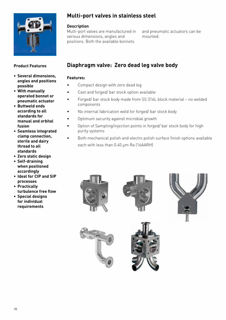
Multi-portvalvesinstainlesssteel
Description
Product Features
• Severaldimensions,angles and positions possible
• Withmanuallyoperated bonnet or pneumatic actuator
• Buttweldendsaccording to all standards for manual and orbital fusion
• Seamlessintegratedclamp connection, sterile and dairy thread to all standards
• Zerostaticdesign• Self-draining
when positioned accordingly
• IdealforCIPandSIPprocesses
• Practicallyturbulencefreeflow
• Specialdesignsfor individual requirements
Diaphragmvalve:Zerodeadlegvalvebody
Features:
• Compactdesignwithzerodeadleg
• Castandforged/barstockoptionavailable
• Forged/barstockbodymadefromSS316Lblockmaterial–noweldedcomponents
• Nointernalfabricationweldforforged/barstockbody
• Optimumsecurityagainstmicrobialgrowth
• OptionofSampling/injectionpointsinforged/barstockbodyforhighpurity systems
• Bothmechanicalpolishandelectropolishsurfacefinishoptionsavailable
each with less than 0.40 µm Ra (16AARH)
Multi-port valves are manufactured invarious dimensions, angles andpositions. Both the available bonnets
and pneumatic actuators can bemounted.

19
Diaphragms
Diaphragmqualities
Pressure/TemperatureRange(Medium)
Code Description Material Temperature°C Shore-Ahardkg/cm
Tensilestr.kg/cm2 min.
F2 EPDM Ethylene-Propylene-Diene-Rub-ber as per FDA -40 140 68–70 150
70 FPM Viton -5 150 74 13080 Si Silicon (U.S.P. Class 6) -40 175 68–70 7093/30 PTFE/IIR PTFE/Butyl -5 15093/70 PTFE/FPM PTFE/Viton -5 175
PTFE/EPDM PTFE/EPDM -5 150PTFE/EPDM PTFE/EPDM«LOW CREEP» -5 150PTFE/IIR PTFE/BUTYL«LOW CREEP» -5 150

20
GFIND/14/CAT/SS/MTL/V0.1©Georg Fischer Piping Systems Pvt. LtdMumbai, 2014Printed in India
* These products are for sale in indian territory only
Adding Quality to People’s Lives
Head Office GeorgFischerPipingSystemsPvt.ltd.B -9, Kopri Village, Above China Vally Hotel, Opp. Hiranandani Foundation School,Powai, Mumbai– 400 076Maharashtra, IndiaContact: 022-4007 2012/[email protected]@Georgfischer.com
Ahmedabad OfficeGeorgFischerPipingSystemsPvt.ltd.Regional Office, 906, Sukhsagar Complex, Ashram Road, Usmanpura, Ahmedabad – 380 014Gujarath, India Contact: 079-27561510
Delhi Office:GeorgFischerPipingSystemsPvt.ltd.732-733, 8 Th Floor, West End Mall,Janakpuri Dist. Centre,New Delhi – 110058Contact: 011-45520494 /95/97
Bengaluru Office:GeorgFischerPipingSystemsPvt.ltd.No-9, 1 St Floor, Opp. Hotel Coral Tree, R. T. Nagar, Main Road Bangluru – 32Contact: 080-41135134
Chennai Office:GeorgFischerPipingSystemsPvt.Flat No -10, Door No -12, 3 Rd Floor,Swathi Complex, Bazullah Road,T Nagar, Chennai – 600 017Contact: 044-45502403
www.gfps.com
Service Centre GeorgFischerPipingSystemsPvt.ltdGala No. J-1, Jai Matadi Compound, Ranjan Construction,Thane-Bhiwandi Road,Kalher Village, Bhiwandi – 421302,Contact: 091-9819195443


