19
STAMP/STPA case study Range Extender System for Electric Vehicles Hossam Yahia & Esmaiel Fawzy VIAS - Egypt
STAMP/STPA case study
Range Extender System for Electric Vehicles
Hossam Yahia &
Esmaiel Fawzy
VIAS - Egypt
March 2013 I 2
Agenda
Introduction to electric and hybrid vehicles
Range extender system
High level safety control structure
STPA application
Comparison with results from FTA/CPA
Conclusion
Q&A
March 2013 I 3
Introduction to electric and hybrid vehicles
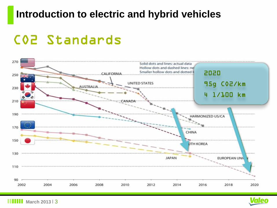
CO2 Standards
2020
95g CO2/km
4 l/100 km
March 2013 I 4
Introduction to electric and hybrid vehicles
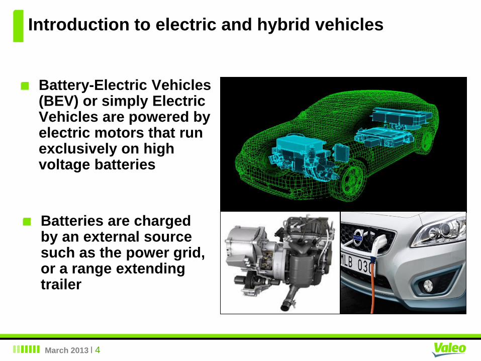
Battery-Electric Vehicles (BEV) or simply Electric Vehicles are powered by electric motors that run exclusively on high voltage batteries
Batteries are charged by an external source such as the power grid, or a range extending trailer
March 2013 I 5
Introduction to electric and hybrid vehicles
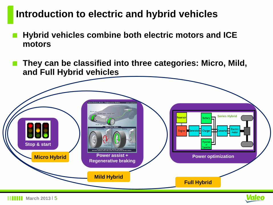
Hybrid vehicles combine both electric motors and ICE motors
They can be classified into three categories: Micro, Mild, and Full Hybrid vehicles
Power assist +
Regenerative braking
Mild Hybrid
Power optimization
Full Hybrid
Series Hybrid
Stop & start
Micro Hybrid
March 2013 I 6
Range extender system
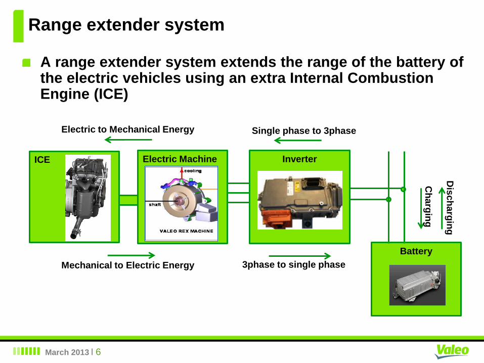
A range extender system extends the range of the battery of the electric vehicles using an extra Internal Combustion Engine (ICE)
ICE Electric Machine Inverter
Battery
Electric to Mechanical Energy
Mechanical to Electric Energy
Single phase to 3phase
3phase to single phase
Ch
arg
ing
Dis
ch
arg
ing
March 2013 I 7
Range extender system
ICE Electric Machine Inverter
Battery
ECU
Another supplier
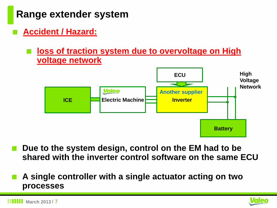
Accident / Hazard:
loss of traction system due to overvoltage on High voltage network
Due to the system design, control on the EM had to be shared with the inverter control software on the same ECU
A single controller with a single actuator acting on two processes
High
Voltage
Network
March 2013 I 8
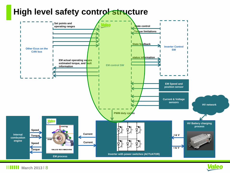
High level safety control structure
EM process
HV Battery charging
process
Internal
combustion
engine
Inverter with power switches (ACTUATOR)
EM control SW
Other Ecus on the
CAN bus
Set points and
operating ranges
EM actual operating values
estimated torque, and fault
information
EM Speed and
position sensor
Current & Voltage
sensors HV network
State control
Torque limitations
Inverter Control
SW
State feedback
status information
PWM duty cycles
Current
Current
I & V
I & V
Speed
Torque
Speed
Torque
March 2013 I 9
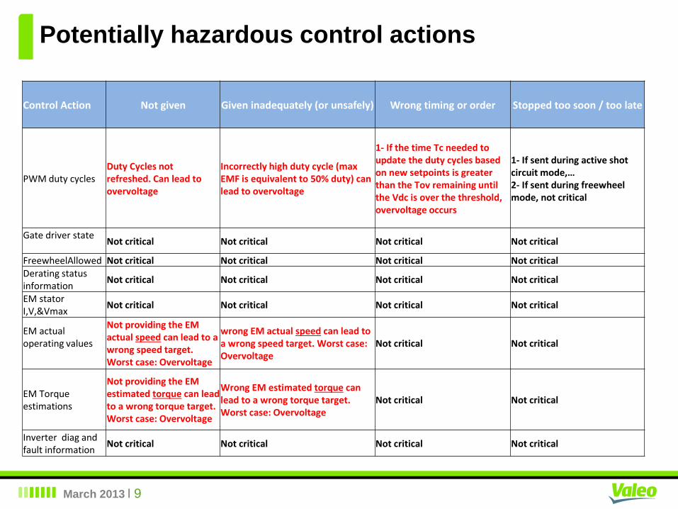
Potentially hazardous control actions
Control Action Not given Given inadequately (or unsafely) Wrong timing or order Stopped too soon / too late
PWM duty cycles Duty Cycles not refreshed. Can lead to overvoltage
Incorrectly high duty cycle (max EMF is equivalent to 50% duty) can lead to overvoltage
1- If the time Tc needed to update the duty cycles based on new setpoints is greater than the Tov remaining until the Vdc is over the threshold, overvoltage occurs
1- If sent during active shot circuit mode,… 2- If sent during freewheel mode, not critical
Gate driver state
Not critical Not critical Not critical Not critical
FreewheelAllowed Not critical Not critical Not critical Not critical Derating status information
Not critical Not critical Not critical Not critical
EM stator I,V,&Vmax
Not critical Not critical Not critical Not critical
EM actual operating values
Not providing the EM actual speed can lead to a wrong speed target. Worst case: Overvoltage
wrong EM actual speed can lead to a wrong speed target. Worst case: Overvoltage
Not critical Not critical
EM Torque estimations
Not providing the EM estimated torque can lead to a wrong torque target. Worst case: Overvoltage
Wrong EM estimated torque can lead to a wrong torque target. Worst case: Overvoltage
Not critical Not critical
Inverter diag and fault information
Not critical Not critical Not critical Not critical
March 2013 I 10
First level safety Constraints
We could identify at that level 7 constraints
5 of them are in the form of normative requirements (SW
shall do…)
2 of them in the form of undesirable events (SW shall not
do)
1 of the normative requirements is related to a hazard
caused by a real-time error
March 2013 I 11
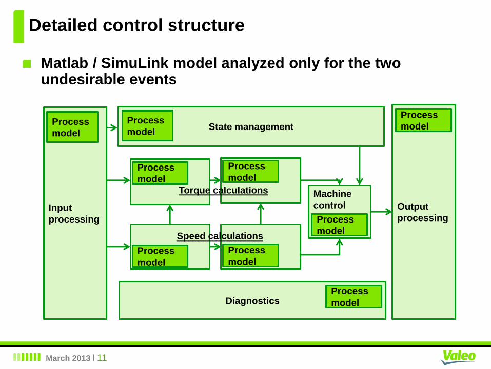
Detailed control structure
Matlab / SimuLink model analyzed only for the two undesirable events
Input
processing
Output
processing
Machine
control
State management
Diagnostics
Torque calculations
Speed calculations
Process
model
Process
model
Process
model
Process
model
Process
model
Process
model
Process
model
Process
model
Process
model
March 2013 I 12
Detailed safety Constraints
The 2 undesirable events were analyzed down to 16 normative software constraints
So, total number of 5 + 16 = 21 software constraint
March 2013 I 13
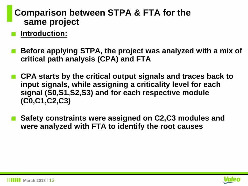
Comparison between STPA & FTA for the same project
Introduction:
Before applying STPA, the project was analyzed with a mix of critical path analysis (CPA) and FTA
CPA starts by the critical output signals and traces back to input signals, while assigning a criticality level for each signal (S0,S1,S2,S3) and for each respective module (C0,C1,C2,C3)
Safety constraints were assigned on C2,C3 modules and were analyzed with FTA to identify the root causes
March 2013 I 14
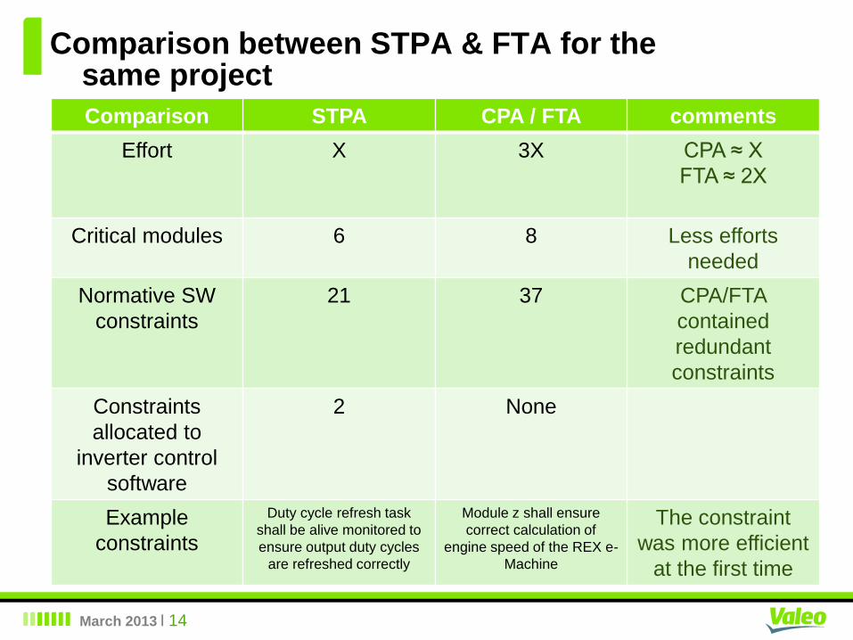
Comparison between STPA & FTA for the same project
Comparison STPA CPA / FTA comments
Effort X 3X CPA ≈ X
FTA ≈ 2X
Critical modules 6 8 Less efforts
needed
Normative SW
constraints
21 37 CPA/FTA
contained
redundant
constraints
Constraints
allocated to
inverter control
software
2 None
Example
constraints
Duty cycle refresh task
shall be alive monitored to
ensure output duty cycles
are refreshed correctly
Module z shall ensure
correct calculation of
engine speed of the REX e-
Machine
The constraint
was more efficient
at the first time
March 2013 I 15
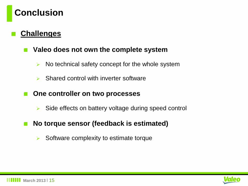
Conclusion
Challenges
Valeo does not own the complete system
No technical safety concept for the whole system
Shared control with inverter software
One controller on two processes
Side effects on battery voltage during speed control
No torque sensor (feedback is estimated)
Software complexity to estimate torque
March 2013 I 16
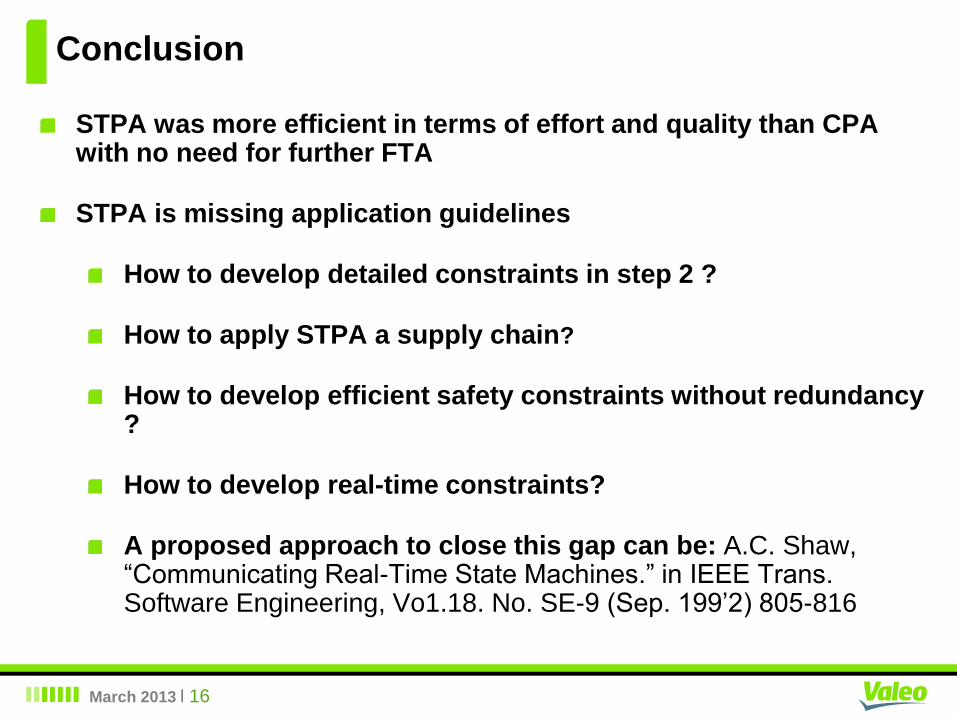
Conclusion
STPA was more efficient in terms of effort and quality than CPA with no need for further FTA
STPA is missing application guidelines
How to develop detailed constraints in step 2 ?
How to apply STPA a supply chain?
How to develop efficient safety constraints without redundancy ?
How to develop real-time constraints?
A proposed approach to close this gap can be: A.C. Shaw, “Communicating Real-Time State Machines.” in IEEE Trans. Software Engineering, Vo1.18. No. SE-9 (Sep. 199’2) 805-816
March 2013 I 17
Conclusion
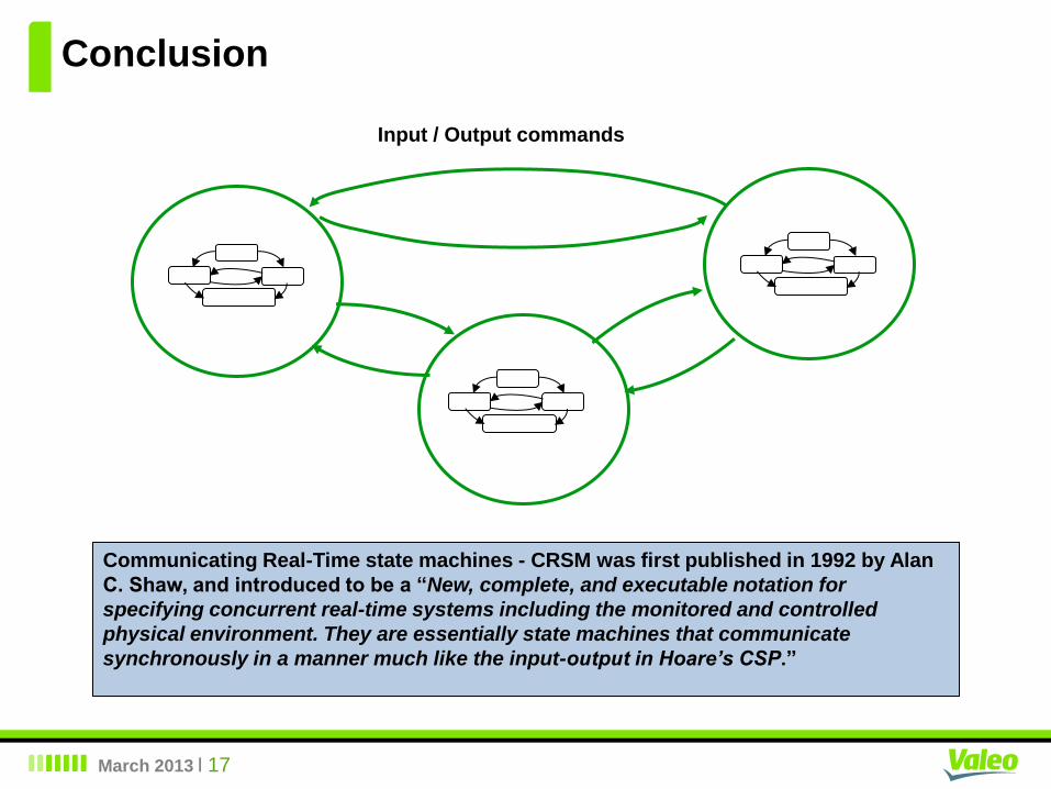
Input / Output commands
Communicating Real-Time state machines - CRSM was first published in 1992 by Alan
C. Shaw, and introduced to be a “New, complete, and executable notation for
specifying concurrent real-time systems including the monitored and controlled
physical environment. They are essentially state machines that communicate
synchronously in a manner much like the input-output in Hoare’s CSP.”

Q & A