August 2005 Page 5B.21 New York Standards and Specifications For Erosion and Sediment Control STANDARD AND SPECIFICATIONS FOR ROCK OUTLET PROTECTION Definition A section of rock protection placed at the outlet end of the culverts, conduits, or channels. Purpose The purpose of the rock outlet protection is to reduce the depth, velocity, and energy of water, such that the flow will not erode the receiving downstream reach. Scope This standard applies to the planning, design, and construction of rock riprap and gabions for protection of downstream areas. It does not apply to rock lining of channels or streams. Conditions Where Practice Applies This practice applies where discharge velocities and energies at the outlets of culverts, conduits, or channels are sufficient to erode the next downstream reach. This applies to: 1. Culvert outlets of all types. 2. Pipe conduits from all sediment basins, dry storm water ponds, and permanent type ponds. 3. New channels constructed as outlets for culverts and conduits. Design Criteria The design of rock outlet protection depends entirely on the location. Pipe outlet at the top of cuts or on slopes steeper than 10 percent, cannot be protected by rock aprons or riprap sections due to re-concentration of flows and high velocities encountered after the flow leaves the apron. Many counties and state agencies have regulations and design procedures already established for dimensions, type and size of materials, and locations where outlet protection is required. Where these requirements exist, they shall be followed. Tailwater Depth The depth of tailwater immediately below the pipe outlet must be determined for the design capacity of the pipe. If the tailwater depth is less than half the diameter of the outlet pipe, and the receiving stream is wide enough to accept divergence of the flow, it shall be classified as a Minimum Tailwater Condition; see Figure 5B.12 on page 5B.25 as an example. If the tailwater depth is greater than half the pipe diameter and the receiving stream will continue to confine the flow, it shall be classified as a Maximum Tailwater Condition; see Figure 5B.13 on page 5B.26 as an example. Pipes which outlet onto flat areas with no defined channel may be assumed to have a Minimum Tailwater Condition; see Figure 5B.12 on page 5B.25 as an example. Apron Size The apron length and width shall be determined from the curves according to the tailwater conditions: Minimum Tailwater – Use Figure 5B.12 on page 5B.25 Maximum Tailwater – Use Figure 5B.13 on page 5B.26 If the pipe discharges directly into a well defined channel, the apron shall extend across the channel bottom and up the channel banks to an elevation one foot above the maximum tailwater depth or to the top of the bank, whichever is less. The upstream end of the apron, adjacent to the pipe, shall have a width two (2) times the diameter of the outlet pipe, or conform to pipe end section if used.
Transcript
August 2005 Page 5B.21 New York Standards and Specifications For Erosion and Sediment Control
STANDARD AND SPECIFICATIONS FOR
ROCK OUTLET PROTECTION
Definition A section of rock protection placed at the outlet end of the culverts, conduits, or channels. Purpose The purpose of the rock outlet protection is to reduce the depth, velocity, and energy of water, such that the flow will not erode the receiving downstream reach. Scope This standard applies to the planning, design, and construction of rock riprap and gabions for protection of downstream areas. It does not apply to rock lining of channels or streams. Conditions Where Practice Applies This practice applies where discharge velocities and energies at the outlets of culverts, conduits, or channels are sufficient to erode the next downstream reach. This applies to: 1. Culvert outlets of all types. 2. Pipe conduits from all sediment basins, dry storm water ponds, and permanent type ponds. 3. New channels constructed as outlets for culverts and conduits.
Design Criteria
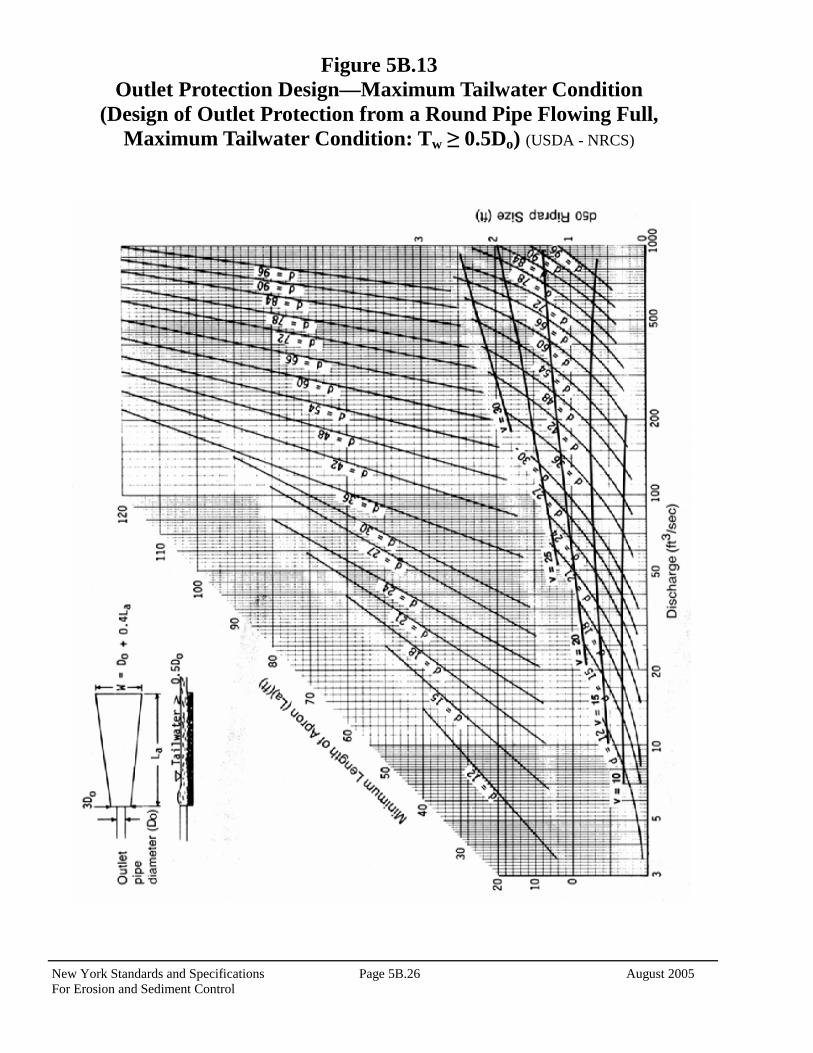
The design of rock outlet protection depends entirely on the location. Pipe outlet at the top of cuts or on slopes steeper than 10 percent, cannot be protected by rock aprons or riprap sections due to re-concentration of flows and high velocities encountered after the flow leaves the apron. Many counties and state agencies have regulations and design procedures already established for dimensions, type and size of materials, and locations where outlet protection is required. Where these requirements exist, they shall be followed. Tailwater Depth The depth of tailwater immediately below the pipe outlet must be determined for the design capacity of the pipe. If the tailwater depth is less than half the diameter of the outlet pipe, and the receiving stream is wide enough to accept divergence of the flow, it shall be classified as a Minimum Tailwater Condition; see Figure 5B.12 on page 5B.25 as an example. If the tailwater depth is greater than half the pipe diameter and the receiving stream will continue to confine the flow, it shall be classified as a Maximum Tailwater Condition; see Figure 5B.13 on page 5B.26 as an example. Pipes which outlet onto flat areas with no defined channel may be assumed to have a Minimum Tailwater Condition; see Figure 5B.12 on page 5B.25 as an example.
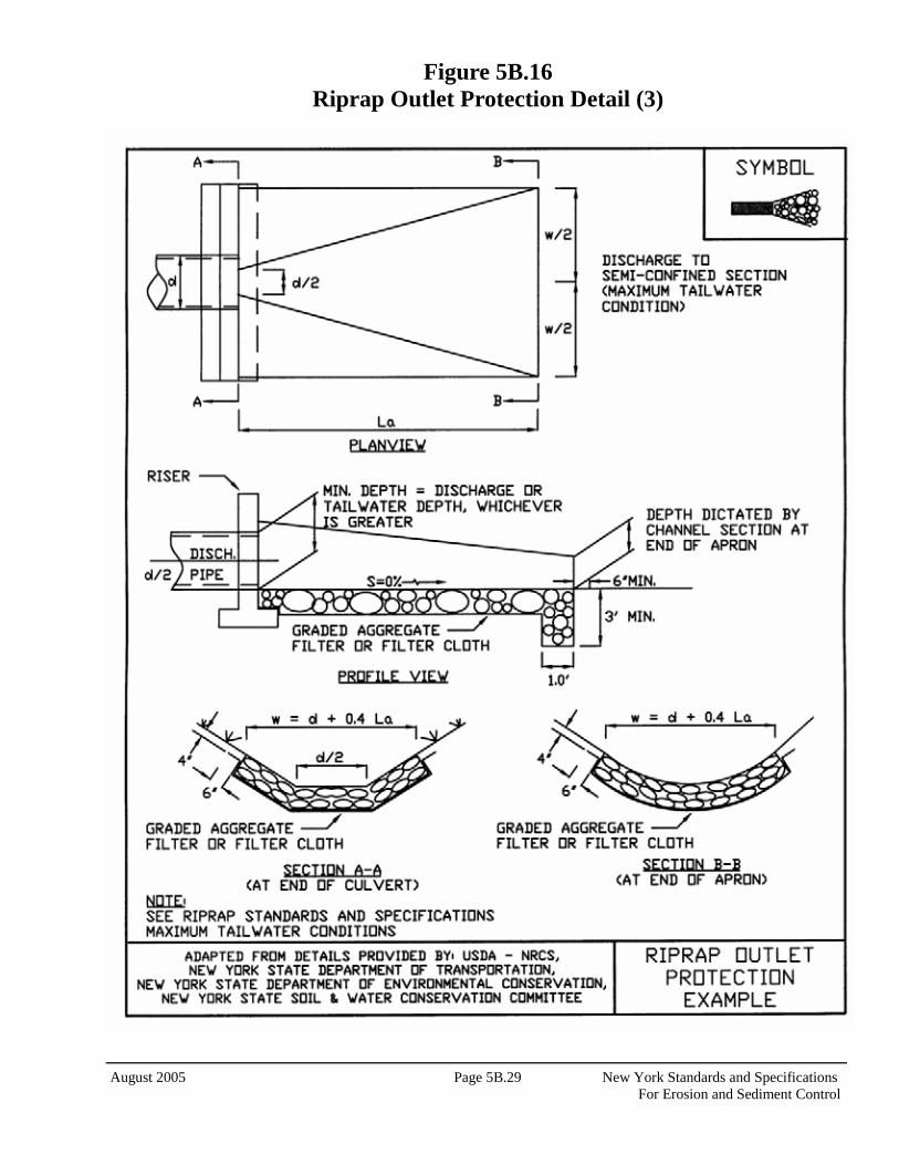
Apron Size The apron length and width shall be determined from the curves according to the tailwater conditions: Minimum Tailwater – Use Figure 5B.12 on page 5B.25 Maximum Tailwater – Use Figure 5B.13 on page 5B.26 If the pipe discharges directly into a well defined channel, the apron shall extend across the channel bottom and up the channel banks to an elevation one foot above the maximum tailwater depth or to the top of the bank, whichever is less. The upstream end of the apron, adjacent to the pipe, shall have a width two (2) times the diameter of the outlet pipe, or conform to pipe end section if used.
New York Standards and Specifications Page 5B.22 August 2005 For Erosion and Sediment Control
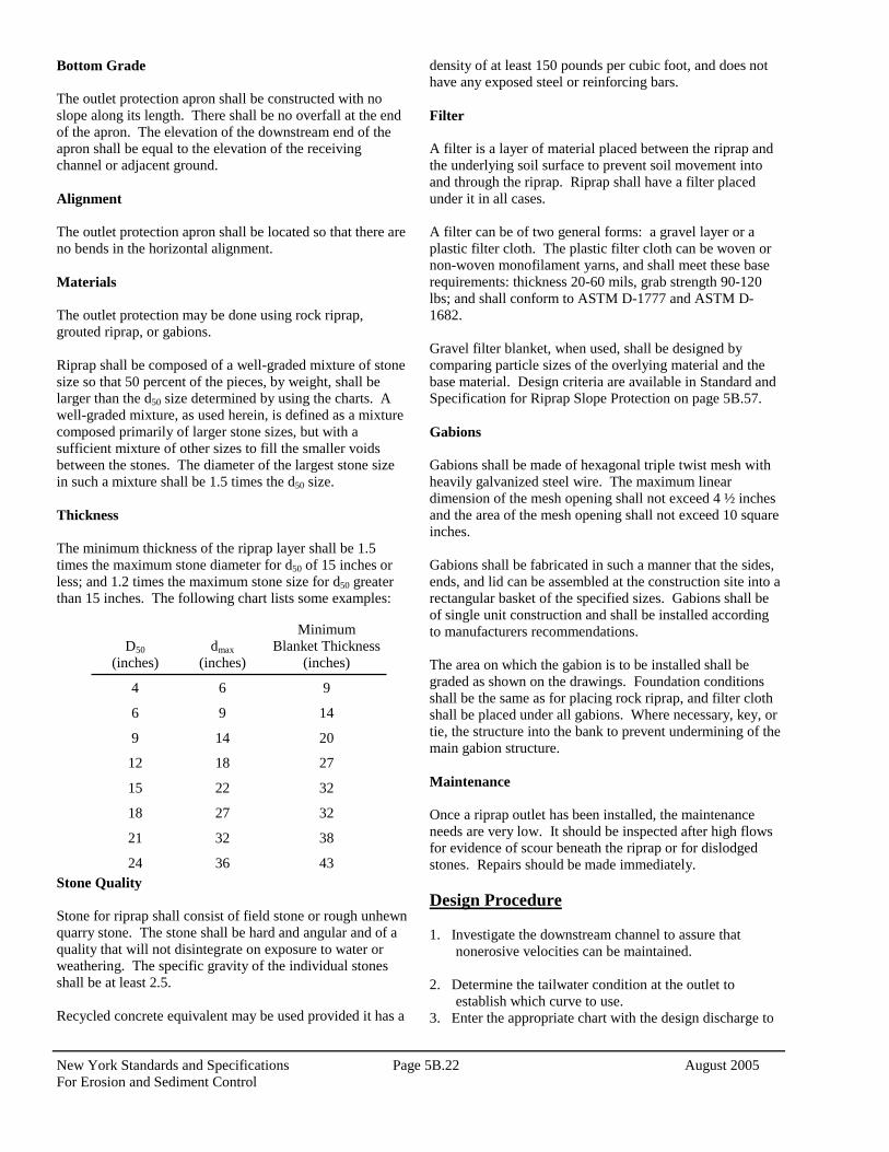
Bottom Grade The outlet protection apron shall be constructed with no slope along its length. There shall be no overfall at the end of the apron. The elevation of the downstream end of the apron shall be equal to the elevation of the receiving channel or adjacent ground. Alignment The outlet protection apron shall be located so that there are no bends in the horizontal alignment. Materials The outlet protection may be done using rock riprap, grouted riprap, or gabions. Riprap shall be composed of a well-graded mixture of stone size so that 50 percent of the pieces, by weight, shall be larger than the d50 size determined by using the charts. A well-graded mixture, as used herein, is defined as a mixture composed primarily of larger stone sizes, but with a sufficient mixture of other sizes to fill the smaller voids between the stones. The diameter of the largest stone size in such a mixture shall be 1.5 times the d50 size. Thickness
The minimum thickness of the riprap layer shall be 1.5 times the maximum stone diameter for d50 of 15 inches or less; and 1.2 times the maximum stone size for d50 greater than 15 inches. The following chart lists some examples:
Stone Quality Stone for riprap shall consist of field stone or rough unhewn quarry stone. The stone shall be hard and angular and of a quality that will not disintegrate on exposure to water or weathering. The specific gravity of the individual stones shall be at least 2.5. Recycled concrete equivalent may be used provided it has a
density of at least 150 pounds per cubic foot, and does not have any exposed steel or reinforcing bars. Filter A filter is a layer of material placed between the riprap and the underlying soil surface to prevent soil movement into and through the riprap. Riprap shall have a filter placed under it in all cases. A filter can be of two general forms: a gravel layer or a plastic filter cloth. The plastic filter cloth can be woven or non-woven monofilament yarns, and shall meet these base requirements: thickness 20-60 mils, grab strength 90-120 lbs; and shall conform to ASTM D-1777 and ASTM D-1682. Gravel filter blanket, when used, shall be designed by comparing particle sizes of the overlying material and the base material. Design criteria are available in Standard and Specification for Riprap Slope Protection on page 5B.57. Gabions Gabions shall be made of hexagonal triple twist mesh with heavily galvanized steel wire. The maximum linear dimension of the mesh opening shall not exceed 4 ½ inches and the area of the mesh opening shall not exceed 10 square inches. Gabions shall be fabricated in such a manner that the sides, ends, and lid can be assembled at the construction site into a rectangular basket of the specified sizes. Gabions shall be of single unit construction and shall be installed according to manufacturers recommendations. The area on which the gabion is to be installed shall be graded as shown on the drawings. Foundation conditions shall be the same as for placing rock riprap, and filter cloth shall be placed under all gabions. Where necessary, key, or tie, the structure into the bank to prevent undermining of the main gabion structure. Maintenance Once a riprap outlet has been installed, the maintenance needs are very low. It should be inspected after high flows for evidence of scour beneath the riprap or for dislodged stones. Repairs should be made immediately. Design Procedure 1. Investigate the downstream channel to assure that
nonerosive velocities can be maintained. 2. Determine the tailwater condition at the outlet to
establish which curve to use. 3. Enter the appropriate chart with the design discharge to
D50
(inches)
dmax
(inches)
Minimum Blanket Thickness
(inches)
4 6 9
6 9 14
9 14 20
12 18 27
15 22 32
18 27 32
21 32 38
24 36 43
August 2005 Page 5B.23 New York Standards and Specifications For Erosion and Sediment Control
determine the riprap size and apron length required. It is noted that references to pipe diameters in the charts are based on full flow. For other than full pipe flow, the parameters of depth of flow and velocity must be used to adjust the design discharges.
4. Calculate apron width at the downstream end if a flare
section is to be employed.
Examples Example 1: Pipe Flow (full) with discharge to unconfined section. Given: A circular conduit flowing full. Q = 280 cfs, diam. = 66 in., tailwater (surface) is 2 ft.
above pipe invert (minimum tailwater condition). Find: Read d50 = 1.2 and apron length (La) = 38 ft. Apron width = diam. + La = 5.5 + 38 = 43.5 ft. Use: d50 = 15”, dmax = 22”, blanket thickness = 32” Example 2: Box Flow (partial) with high tailwater Given: A box conduit discharging under partial flow conditions. A concrete box 5.5 ft. x 10 ft. flowing 5.0 ft. deep, Q = 600 cfs and tailwater surface is 5 ft. above invert (max.
tailwater condition). Since this is not full pipe and does not directly fit the nomograph assumptions of Figure 7B.13 substitute depth as the diameter, to find a discharge equal to full pipe flow for that diameter, in this case 60 inches. Since, Q = AV and A = π D2 4 First, compute velocity: V = (Q/A) = (600/(5) (10)) = 12 fps Then substituting:
Q = π D2 x V = 3.14 (5 ft)2 x 12 fps = 236 cfs 4 4
At the intersection of the curve d = 60 in. and Q = 236 cfs, read d50 = 0.4 ft. Then reading the d = 60 in. curve, read apron length (La) = 40 ft.
Apron width, W = conduit width + (6.4)(La) = 10 + (0.4)(40) = 26 ft. Example 3: Open Channel Flow with Discharge to Unconfined Section Given: A trapezoidal concrete channel 5 ft. wide with 2:1 side slopes is flowing 2 ft. deep, Q = 180 cfs (velocity = 10 fps) and the tailwater surface downstream is 0.8 ft. (minimum tailwater condition). Find: Using similar principles as Example 2, compute equivalent discharge for a 2 foot, using depth as a diameter, circular pipe flowing full at 10 feet per second. Velocity: Q = π (2ft)2 x 10 fps = 31.4 cfs 4 At intersection of the curve, d = 24 in. and Q = 32 cfs, read
d50 = 0.6 ft. Then reading the d = 24 in. curve, read apron length (La) =
20 ft. Apron width, W = bottom width of channel + La = 5 + 20 =
25 ft. Example 4: Pipe flow (partial) with discharge to a confined section Given: A 48 in. pipe is discharging with a depth of 3 ft. Q = 100 cfs, and discharge velocity of 10 fps (established from partial flow analysis) to a confined trapezoidal channel with a 2 ft. bottom, 2:1 side slopes, n = .04, and grade of 0.6%. Calculation of the downstream channel (by Manning’s Equation) indicates a normal depth of 3.1 ft. and normal velocity of 3.9 fps. Since the receiving channel is confined, the maximum tailwater condition controls. Find: discharge using previous principles:
Q = π (3ft)2 x 10 fps = 71 cfs 4
At the intersection of d = 36 in. and Q = 71 cfs, read d50 = 0.3 ft. Reading the d = 36” curve, read apron length (La) = 30 ft. Since the maximum flow depth in this reach is 3.1 ft., that is the minimum depth of riprap to be maintained for the entire length.
New York Standards and Specifications Page 5B.24 August 2005 For Erosion and Sediment Control
Construction Specifications 1. The subgrade for the filter, riprap, or gabion shall be
prepared to the required lines and grades. Any fill required in the subgrade shall be compacted to a density of approximately that of the surrounding undisturbed material.
2. The rock or gravel shall conform to the specified
grading limits when installed respectively in the riprap or filter.
3. Filter cloth shall be protected from punching, cutting,
or tearing. Any damage other than an occasional small hole shall be repaired by placing another piece of cloth over the damaged part or by completely replacing the cloth. All overlaps, whether for repairs or for joining two pieces of cloth shall be a minimum of one foot.
4. Stone for the riprap or gabion outlets may be placed by
equipment. Both shall each be constructed to the full course thickness in one operation and in such a manner as to avoid displacement of underlying materials. The stone for riprap or gabion outlets shall be delivered and placed in a manner that will ensure that it is reasonably homogenous with the smaller stones and spalls filling the voids between the larger stones. Riprap shall be placed in a manner to prevent damage to the filter blanket or filter cloth. Hand placement will be required to the extent necessary to prevent damage to the permanent works.
August 2005 Page 5B.25 New York Standards and Specifications For Erosion and Sediment Control


![National Fire Protection Association Report - nfpa.org · PDF fileSecond Revision No. 169-NFPA 13-2014 [ Section No. 3.8.1.12 ] 3.8.1.12 Pumper Outlet. The hydrant outlet intended](https://static.documents.pub/doc/80x56/5a712a367f8b9abb538c93db/national-fire-protection-association-report-nfpaorg-nbsppdf-filesecond.jpg)


