SECTION 55.04 CONNECTIONS TO EXISTING MANHOLES OR CATCH BASINS......................................................................................... 16
STANDARD CONSTRUCTION SPECIFICATIONS FOR STORM DRAIN SYSTEMS
DIVISION 55
SECTION 55.01 GENERAL
Article 1.1 Scope of Work
The Work covered by these Specifications consists of providing all plant, labor, equipment, supplies, transportation, handling, storage and performance of all operations necessary to complete the construction for the pipe laying, jointing, and testing of storm drain systems and culverts.
Requirements for earthwork including trench excavation and backfill are specified in Division 20 - Earthwork.
Article 1.2 Applicable Standards
The latest revision of the following standards of the American Society for Testing and Materials (ASTM), the American Association for State Highway and Transportation Officials (AASHTO), and the American Water Works Association (AWWA) are hereby made part of this Specification.
ASTM A-48 Standard Specifications for Gray Iron Castings ASTM C-76 Specification for Reinforced Concrete ASTM C-150 Specification for Portland Cement ASTM C-478 (AASHTO-199) Specification for Precast Reinforced Concrete Manhole
Sections ASTM C-990 Standard Specification for Joins for Concrete Pipe,
Manholes, and Precast Box Sections Using Preformed Flexible Joint Sealants
ASTM D 1248 Polyethylene Plastics Molding and Extrusion Materials, Type III, High Density
ASTM D 3035 Polyethylene Plastic Pipe (SDR-PR) Based on Controlled Outside Diameter
ASTM D 3350 Polyethylene Plastics and Fittings Materials AASHTO M-36 Corrugated Steel Pipe & Fittings AASHTO M-45 Sand for Cement Mortar AASHTO M-105 Gray Iron Castings AASHTO M-190 Bituminous Coating of CMP AASHTO M-196 Corrugated Aluminum Pipe & Fittings
Page 2 Standard Construction Specifications
Division 55 – Storm Drain Systems Revised 11/08
AASHTO M-198 Joints for Concrete Pipe, Manholes, and Precast Box Sections Using Preformed Flexible Joint Sealants
AASHTO M-245 Precoated Galvanized Steel Culverts and Underdrains AASHTO M-246 Precoated Galvanized Steel Sheets for Culverts and
Underdrains AASHTO M-274 Corrugated Aluminized Pipe and Fittings AASHTO M-252 Corrugated Polyethylene Tubing 3"-10" diameter AASHTO M-294 Corrugated Polyethylene Pipe, 12" diameter and larger AASHTO M-306 Drainage, Sewer, Utility, and Related Castings Federal Specification SS-S-210
Sealing Compound, Preformed Plastic, for Expansion Joints and Pipe Joints
Article 1.3 Surveys
The Contractor shall layout in the field the alignment and grade of Work to be done under the Contract. The Contractor shall be responsible for the preservation of all line stakes, grade stakes, and hubs. In the event of their loss or destruction, the Contractor shall be responsible for their proper replacement. The line and grade for pipe lines shall be given from reference hubs offset from each manhole or cleanout. The Contractor shall be responsible for the transfer of the control points from the reference hubs to such hubs or batter boards as he may desire or need for the prosecution of the Work.
A Professional Land Surveyor licensed in the State of Alaska, subcontracted to the Contractor, shall perform all surveying, project control, monumentation, staking, profiles, and cross section measurements for pay item quantities. All personnel involved in measuring and recording survey data shall be directly employed by the Surveying Subcontractor and shall not be employed by the Contractor or any of the other Subcontractors for the duration of the Project. Failure to adhere to this requirement will result in non-payment for all Work affected by non-compliance. All survey work will adhere to Division 65 – Construction Survey.
Article 1.4 Concrete and Mortar
A. Miscellaneous Concrete
All concrete used in the construction of storm drains with the exception of precast manholes, manhole risers, cones, and catch basin barrels shall be Class A-3. Concrete Work shall conform to Division 30 – Portland Cement Concrete.
B. Mortar
Cement for mortar used in the construction of storm drain shall conform with the requirements of ASTM C-150, Type II. Sand shall conform with the requirements of AASHTO M-45. The mortar shall be composed of one (1) part cement and three (3) parts sand. The addition of lime is not permitted.
Page 3 Standard Construction Specifications
Division 55 – Storm Drain Systems Revised 11/08
Article 1.5 Payment - General
Payment for all Work included in this Division shall be in accordance with Division 10, Section 10.07 - Measurement and Payment and shall include full payment for all Work described.
Page 4 Standard Construction Specifications
Division 55 – Storm Drain Systems Revised 11/08
SECTION 55.02 FURNISH AND INSTALL PIPE
Article 2.1 General
The Work under this Section consists of the performance of all operations pertaining to furnishing and installing pipe for storm drain systems.
In the case of Owner-furnished pipe, the Owner shall allot to the Project pipe to accomplish the Work in amounts, exactly matching the Contractor's pay quantities for pipe. Any surplus pipe left over from this allotment at the end of the Project shall be returned from the Contractor's job sites to the Owner's designated pipe yard. If the Contractor withdraws from the Owner's pipe yard more than the amount required to match the payment quantities, the Contractor shall pay the Owner on the basis of the Owner's invoice price for pipe (including freight), plus ten percent (10%) overhead to reimburse the Owner for handling, warehousing, inspection, and administration.
Article 2.2 Material
A. General
All piping shall be in accordance with the Contract Documents conforming to the size and class shown and specified. Changes in class shall be made within one-half of a pipe length of the station indicated on the Drawings.
B. Corrugated Metal Pipe (CMP)
Corrugated metal pipe shall only be used in culvert crossings and similar applications. CMP use in a piped storm drain system is prohibited without approval from Street Maintenance and the Municipal Engineer. Corrugated metal pipe is intended to refer to both steel and aluminum. The pipe shall conform to the following specifications:
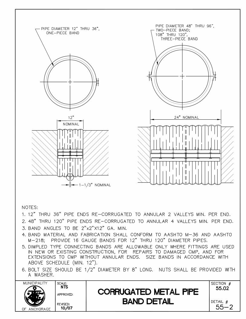
1. Steel: Corrugated steel pipe shall meet the requirements of AASHTO M-36.
2. Aluminum: Corrugated aluminum pipe shall conform to the requirements of the AASHTO M-196.
3. Aluminum Coated (Aluminized): Corrugated aluminized pipe shall conform to the requirements of AASHTO M-36 and AASHTO M-274.
All CMP fittings shall be fabricated in a workmanlike manner, develop the full strength of the material being joined, and finished to conform to the appropriate requirements of AASHTO M-36, AASHTO M-196 and AASHTO M-274.
Corrugated steel and aluminum pipe shall jointed by using coupling bands applied as recommended by the manufacturer and approved by the Engineer.
Page 5 Standard Construction Specifications
Division 55 – Storm Drain Systems Revised 11/08
Dissimilar metals may only be used in extending in place metal CMP and reattachment of dissimilar metal end sections provided an electrical insulating material, at least one-sixteenth inch (1/16”) in thickness, is used to separate the dissimilar materials.
All angles, bolts, and nuts shall be as recommended by the manufacturer for the type of pipe used and as approved by the Engineer.
The metal gauge for pipe to be used shall be in accordance with the Contract Documents.
If bituminous coating of CMP is required, the bituminous coating shall conform to the requirements of AASHTO M-190.
All welding performed by the Contractor on aluminum pipe shall incorporate the use of 4043 or 5356 alloy for welding wire. The welding shall be accomplished by either the "TIG" (tungsten, inert gas shielded) or "MIG" (metal arc welding, inert gas shielded) process.
End Section for Corrugated Metal Pipe - Galvanized steel and aluminum end sections shall be flared, beveled, shop-assembled units to serve as structural, hydraulic and esthetic treatment to corrugated metal pipe culverts. They may be attached to culverts by threaded bolts, by riveting or bolting in accordance with the manufacturer's standard procedure. End sections shall have a turned-down lip or toe plate at the wide end to act as a cutoff. Materials for steel end sections shall be galvanized steel conforming to the requirements of AASHTO M-36. The gauge shall be as follows:
16 Ga. Through 24" in diameter or 29" X 18" pipe-arch
14 Ga. 30" in diameter and 36" X 22" pipe-arch 36" in diameter and 43" X 27" pipe-arch
12 Ga. Over 36" in diameter and 43" X 27" pipe-arch (except that the center panels of 60" in diameter and larger and 72" x 44" pipe-arch and larger, shall be 10 Ga.)
Galvanized stiffener angles shall supplement the usual reinforced side edges for sixty inches (60") in diameter and larger, seventy-nine by forty-nine inch (79" x 49") pipe-arch and larger.
If the end section is shop attached to a stub of pipe, the pipe stub shall not be lighter in gauge than the end section.
Materials for aluminum end sections shall comply with the provisions of AASHTO M-196 and fabrication shall comply with the requirements above.
Page 6 Standard Construction Specifications
Division 55 – Storm Drain Systems Revised 11/08
C. Precoated Corrugated Metal Pipe (PCMP)
All precoated corrugated metal pipe and connecting bands shall be coated to meet the AASHTO DESIGNATION: M-245 and M-246 and the coating shall be 10 mils minimum thickness each side. All exposed edges including any perforated hole edges shall be coated with a liquid coating supplied by the supplier of the precoated corrugated pipe. All metal utilized for the precoated metal pipe shall conform to SubArticle 2.2.B - Corrugated Metal Pipe. All metal pipe utilized shall have a nominal wall thickness of 16 gauge for pipes twenty-one inches (21") and larger and 18 gauge for pipes eighteen inches (18") and smaller, unless otherwise noted.
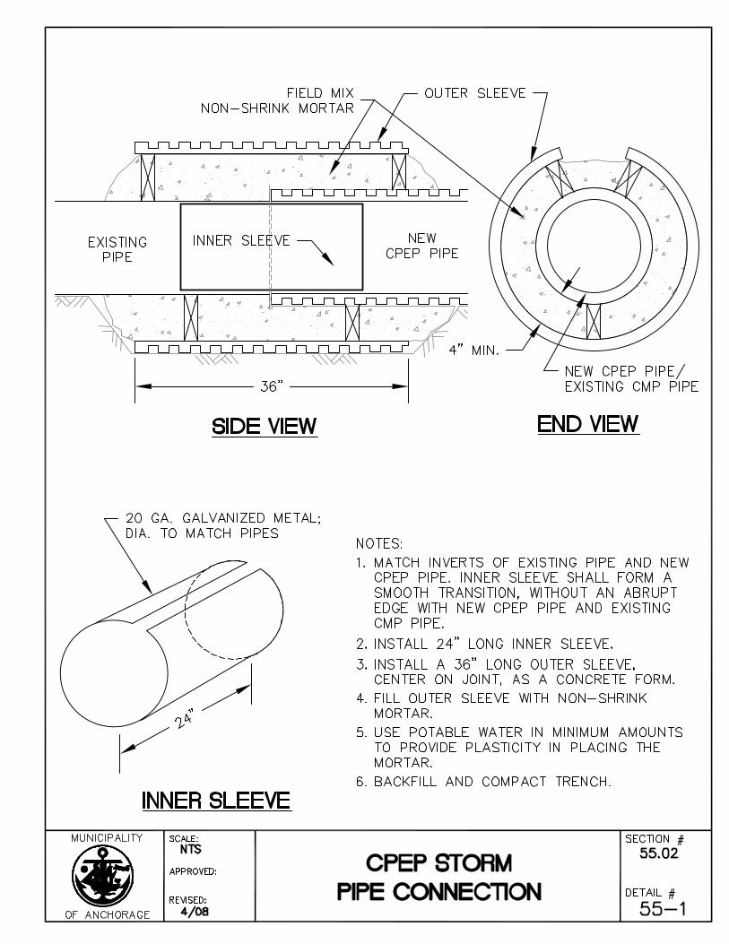
D. Corrugated Polyethylene Pipe (CPEP)
Corrugated Polyethylene pipe shall conform to the following specifications:
1. Three inch through ten inch (3" through 10") diameters: the requirements of AASHTO M-252.
2. Twelve inch (12") and larger diameters: the requirements of AASHTO M-294.
The corrugated Polyethylene Pipe covered by these specifications is classified as follows:
Type C - This pipe shall have a full circular cross-section with a corrugated surface both inside and outside. Corrugations may be either annular or helical.
Type S - This pipe shall have a full circular cross-section, with an outer corrugated pipe wall and a smooth inner liner. Corrugations may be either annular or helical.
Type CP - This pipe shall be Type C with perforations.
Type SP - This pipe shall be Type S with perforations.
All CPEP fittings shall be rotational or blow molded and shall conform to the fitting requirements of AASHTO M-252 or M-294.
Join three inch to ten inch (3" - 10") CPEP with couplings corrugated to match the pipe corrugations or with push-on couplings with locking devices.
Join twelve inch (12") and larger CPEP with couplings, corrugated to match the index in the pipe corrugations and in a width not less than three-quarters (3/4) of the nominal pipe diameter. All couplings shall be manufactured to lap equally to a distance on each jointed pipe, to no less than the diameter of the pipe and shall provide a positive means of closure.
Page 7 Standard Construction Specifications
Division 55 – Storm Drain Systems Revised 11/08
CPEP may be connected to CMP or may be used between or connected to dissimilar metals.
All flared end sections and saddles shall be constructed of the same material as the pipe and shall be factory assembled units to serve as structural, hydraulic, and/or aesthetic end treatment to CPEP culverts. CPEP connections shall be as recommended by the manufacturer. The cost of the end section and saddles shall be incidental to the pipe.
E. High Density Polyethylene Pipe (HDPEP)
High density polyethylene pipe shall conform to the following specifications:
The polyethylene resin shall be classified by ASTM D-1248 as Type III, Class C, Category 5, Grade P34, and have a minimum ASTM D-3350 cell classification of 335434C and a designation of PE 3408 by the Plastic Pipe Institute.
The polyethylene compound shall be suitably protected against ultraviolet light degradation by means of a two percent (2%) concentration of carbon black, well dispersed by pre-compounding in with the resin (by the resin manufacturer).
The pipe shall contain no recycled compound except that generated in the manufacturer's own plant from resin of the same specification from the same raw material supplier. The pipe shall be homogeneous throughout and free of visible cracks, holes, foreign inclusions, or other deleterious defects, and shall be identical in color, density, melt index, and other physical properties.
The pipe shall be designed according to the ISO modified formula in ASTM D-3035. The design pressure rating shall be expressed in terms of the static working pressure in psi for water at 73.4°F according to ASTM D-2837. The minimum allowable pressure rating for gravity pipe shall be 52 psi.
Join pipe lengths to one another using thermal butt fusion. Butt fusion of pipes shall be performed in accordance with the pipe manufacturer's recommendations for equipment and technique, using the correct size equipment and technique. Butt fusion will be performed only by personnel certified as competent by the polyethylene material supplier.
The Contractor shall provide butt fusion equipment compatible with the piping system being used as necessary to complete all joints on the project. All costs in connection with this equipment shall be included in the price bid for pipe installation.
Provide wall pipes or wall fitting as recommended by the pipe manufacturer to connect storm drain and catch basin drain pipes to manholes and catch basins.
Installation of all components shall be accomplished using the manufacturer's recommendations. Unless the Contractor's personnel are certified in the installation of polyethylene pipe, the pipe suppliers shall provide pipe personnel to instruct the
Page 8 Standard Construction Specifications
Division 55 – Storm Drain Systems Revised 11/08
Contractor in the handling, installation, and testing of their products. The Contractor shall provide one supplier's representative at the start of construction for on-site services. Additional technical representative services, if necessary, shall also be at the Contractor's expense.
Random tests of field joints will be made by the Engineer, as necessary, as a quality control measure. The Contractor shall be responsible for removal or repair of unsatisfactory butt fusion joints.
Article 2.3 Construction
A. Excavation and Backfill
Excavation and backfill for furnishing and installing pipe shall be in accordance with Division 20, Section 20.13 - Trench Excavation and Backfill.
B. Pipe Grade and Alignment
Variance of individual pipe sections from established line and grade shall not be greater than those listed in the table below, providing that such variance does not result in a level or reverse sloping invert.
Allowance Diameter (Inches)
Tolerance
(Feet) 8 0.03
10 0.03 12 0.03 14 0.04 16 0.04 18* 0.05
*Note: For all pipe sizes over eighteen inches (18") in diameter, tolerance not to exceed five-hundredths feet (0.05’).
During the progress of the Work, the Contractor shall provide instruments such as transits, levels, laser devices, and other facilities for transferring grades from offset hubs or for setting of batter boards or other construction guides from the control points and bench marks provided by the Contractor. The Contractor shall provide qualified personnel to use such instruments and who shall have the duty and responsibility for placing and maintaining such construction guides. The Contractor shall notify the Engineer forty-eight (48) hours prior to taking measurements on newly installed section of line and/or appurtenances for Record Documents.
If the method of transferring grades from the offset hubs to the pipe require batter-boards, they shall be at least one by six inches (1" x 6") supported on two by
Page 9 Standard Construction Specifications
Division 55 – Storm Drain Systems Revised 11/08
four inch (2" x 4") stakes or approved metal rods and shall be placed every twenty-five feet (25’). At least three boards must be in place at any given time to facilitate checking of line and grade. Both line and grade shall be checked for each piece of pipe laid, except at tunnels where methods acceptable to the Engineer shall be used to carry forward line and grade.
The practice of pushing in uncompacted backfill over a section of pipe to provide a platform for transit and level alignment and grade observations shall be subject to the approval of the Engineer. If intermittent backfilling is allowed backfilling shall be accomplished in accordance with Division 20, Section 20.13 - Trench Excavation and Backfill.
Due to the flexibility of the CPEP, the Contractor shall exert due care while placing bedding and/or filter material and compacting adjacent to and over the pipe. All placement bedding and/or filter material and compaction shall be per the manufacturer's recommendations or as approved by the Engineer.
The Contractor shall exert due care in handling the precoated corrugated metal pipe or while placing bedding and/or filter material around the pipe so as not to damage the coating. The Contractor shall obtain a liquid coating supplied by the precoated corrugated metal supplier which will be painted over scratched or cut sections of the pipe.
C. Pipe Laying
All pipe shall be laid with Class C Bedding unless otherwise required by the Contract Documents or directed by the Engineer.
Pipe laying shall in all cases proceed upgrade. Each pipe shall be laid true to line and grade and in such a manner as to form a close concentric joint with the adjoining pipe. The alignment of the installed pipe shall appear straight to visual observations and shall be such that a full circle of light can be seen between manholes, etc., when sighting along all points of the pipe circumference. Each section of pipe shall be handled carefully and placed accurately. Each section of pipe shall be properly supported to ensure true alignment and an invert which is smooth and free from roughness or irregularity. On helical pipe, the laps shall not impede the flow and all seams shall be aligned uniformly for the length of the run. At all times, when Work is not in progress, open ends of pipe and fittings shall be securely and satisfactorily closed so that no undesirable substances shall enter the pipe or fittings. All pipe shall be laid in accordance with the respective manufacturer's recommendations. Pipe shall not be laid when the bottom of the ditch or the sides to one foot (1’) above the pipe are frozen. Backfill containing frozen material shall not be placed, nor shall the trench be left open during freezing weather so that the temperature of the material near the pipe goes below freezing.
Page 10 Standard Construction Specifications
Division 55 – Storm Drain Systems Revised 11/08
D. Televising Storm Drains.
New storm drains twelve inch (12”) in diameter to thirty-six inch (36”) in diameter shall be inspected by closed circuit television (CCTV) after completion of trench backfill and finished grading but prior to the placement of pavement or permanent trench resurfacing, to determine the existence and extent of any obstructions, structural deficiencies, or sags. Storm drains less than fifty feet (50’) in length for a single run are not required to be televised.
The Contractor shall do the televising. The Engineer reserves the right to retelevise any new storm drain work after the placement of pavement or permanent trench resurfacing, but before acceptance by the Engineer, to determine the existence and extent of any foreign material or obstructions such as, but not necessarily limited to, cement grout, wood, rocks, sand, concrete, or pieces of pipe, and any structural deficiencies or sags precipitated by the permanent resurfacing operations or other Contract Work. The Contractor shall notify the Engineer two (2) working days in advance of the anticipated date of the televising.
Five (5) working days shall be allowed for the Engineer to review each individual video recording of each and every storm drain documented on that particular recording. In the event that any deficiencies or sags are discovered by the Engineer, either by the Contractor's televising or the Engineer's retelevising, three (3) working days shall be allowed for the Engineer to determine whether the deficiencies or sags are repairable in place. If the Engineer determines that the deficiencies or sags are not repairable in place, the affected portion(s) shall be reconstructed in accordance with these Specifications.
The Contractor shall not be entitled to any additional working days due to delays resulting from the correction of any deficiencies or sags, either repairable or non-repairable in place, as determined by televised inspections and the Engineer.
1. General Requirements
a. The video operator must have at least one (1) year of experience with a project of a similar nature within the past two (2) years.
b. Video recordings shall be high quality color on high quality DVD/CD disk format (VHS format maybe considered, must be approved by the Engineer prior to use). Any out-of-focus video recordings or portions thereof, shall be cause for rejection of the video recordings and will necessitate retelevising at the Contractor’s expense.
c. The Contractor shall notify the Engineer two Municipal working days prior to televising.
d. The Contractor shall turn over the original video recordings to the Engineer immediately after recording.
Page 11 Standard Construction Specifications
Division 55 – Storm Drain Systems Revised 11/08
e. Televising shall be done in one direction for the entire length between manholes; each section shall be isolated from the remainder of the storm drain as required. Sufficient water shall be supplied to cause drainage within the isolated section prior to televising.
f. For underground storm drain conduit installations, the maximum operation tolerance for a sag shall be one-hundredth foot (0.01’) per inch of pipe diameter. No sag shall be longer than sixty feet (60’). When televised inspection is used to check for sag, a calibrated device acceptable to the Engineer shall be used to measure the depth of sag.
g. The Contractor shall not be entitled to any additional working days due to delays in securing the videotaping services of a private vendor.
2. Equipment for Televising
Televising equipment shall include the television camera, television monitor, cables, power source, lights and other equipment necessary to the televising operation. The camera shall be specifically designed and constructed for operation in connection with storm drain inspection. The camera shall be self-operative in one hundred percent (100%) humidity conditions. Focal distance shall be adjustable through a range of from one inch (1”) to infinity. The camera shall be self propelled or mounted on skids suitably sized for each pipe diameter to be investigated. Lighting for the camera shall minimize reflective glare. Camera and lighting quality shall be suitable to provide a clear, continuously in-focus picture of the entire inside periphery of the storm drain for all conditions encountered during the Work. Theremote reading footage counter shall be accurate to within one-half percent (0.5%) over measured distance of the particular section being inspected and shall be displayed on the television monitor. The camera, television monitor and other components of the video system shall be capable of producing a minimum three hundred and fifty (350) line resolution color video picture. The equipment shall be capable of televising the entire length in one direction. When televising storm drains the camera shall be capable of scanning the joints for three hundred and sixty degrees (360°).
3. Televising Procedures
The camera shall be moved through the line at a uniform rate, stopping when necessary to ensure proper documentation of the condition of the storm drain but in no case shall the television camera be pulled at a speed greater than thirty feet (30’) per minute. Manual winches, power winches, TV cable and powered rewinds or other devices that do not obstruct the camera view or interface with proper documentation of the storm drain conditions shall be used to move the camera through the storm drain.
Page 12 Standard Construction Specifications
Division 55 – Storm Drain Systems Revised 11/08
If, during the televising operations, the television camera will not pass through an entire manhole section or storm access point section, the Contractor shall reset the equipment in a manner so that the inspection can continue opposite the obstruction. If the television camera encounters an obstruction within a section not accessible to a manhole or storm drain access point, the Contractor shall remove the obstruction by excavation or other appropriate means, replace whatever pipe is necessary, and retelevise the entire section.
Whenever non-remote powered and controlled winches are used to pull the television camera through the line, telephones, radios, or other suitable means of communication shall be set up between the two manholes or storm drain access points of the section being inspected to ensure that adequate communications exist between members of the crew.
The importance of accurate distance measurements is emphasized. Measurement for location of defects shall be above ground by means of a meter device. Marking on the cable, or the like, which would require interpolation for depth of manhole or storm access points, is not acceptable.
The accuracy of the measurement shall be checked daily by use of a walking meter, roll-a-tape, or other suitable device. Measurements shall begin at the centerline of the upstream manhole or storm drain access point, unless permission is given by the Engineer to do otherwise. Distance shall be shown on the video data view at all times.
4. Documentation of Televising
Audio and written documentation shall accompany all video tape(s) submitted to the Municipal Engineer. The voice recording of the video tape(s) shall make brief but informative comments on data of significance, including, but not limited to, the locations of unusual conditions, type and size of connection, collapsed section, the presence of scale and corrosion, and other discernible features.
The video tape(s) shall include the following:
a. Data View i. Report No. ii. Date of TV inspection. iii. Upstream and downstream manhole, storm drain access point
or station numbers. iv. Current distance along reach (tape counter footage). v. Printed labels on tape container and recording cartridge with
location information, date format information, and other descriptive information.
Page 13 Standard Construction Specifications
Division 55 – Storm Drain Systems Revised 11/08
b. Audio i. Date of TV inspection. ii. Confirmation of upstream and downstream manhole, storm
access point or station numbers. iii. Description of pipe size, types and pipe joint length. iv. Description and location of each defect. v. Description and location of each service connection.
c. Written i. Date of TV inspection. ii. Tape number. iii. Location, size, type, and length of pipe. iv. Direction of flow and measurement ("From" manhole/storm
drain access point/station number "To" manhole/storm drain access point/station number).
v. Tape counter numbers (beginning and end). vi. Sketch showing the street and cross streets where the TV
inspection was made. vii. Description and location of each defect. viii. Description and location of each connection.
Article 2.4 Measurement
Measurement for all sizes of pipe shall be based on the horizontal distances and shall be from center to center of manholes, from the center of manholes to center of catch basins, from center of manholes to center of cleanout wye, and from center of manhole to end of pipe including flared end sections. Televising storm drains is considered incidental to the pay item and no separate payment shall be made.
Article 2.5 Basis of Payment
Payment for this Work shall be in accordance with Division 10, Section 10.07 - Measurement and Payment, and shall include full payment for all Work described in this Section.
Payment shall be made under the following units.
ITEM UNIT Furnish, Install, and Televise Pipe (Size, Type, Class, Material, Gauge and Type of Coating) Linear Foot
Page 14 Standard Construction Specifications
Division 55 – Storm Drain Systems Revised 11/08
SECTION 55.03 SUBDRAINS
Article 3.1 General
The Work under this Section consists of the performance of all operations pertaining to furnishing and installing subdrains.
Article 3.2 Material
A. All piping shall be in accordance with the Contract Documents and shall be the sizes shown and specified.
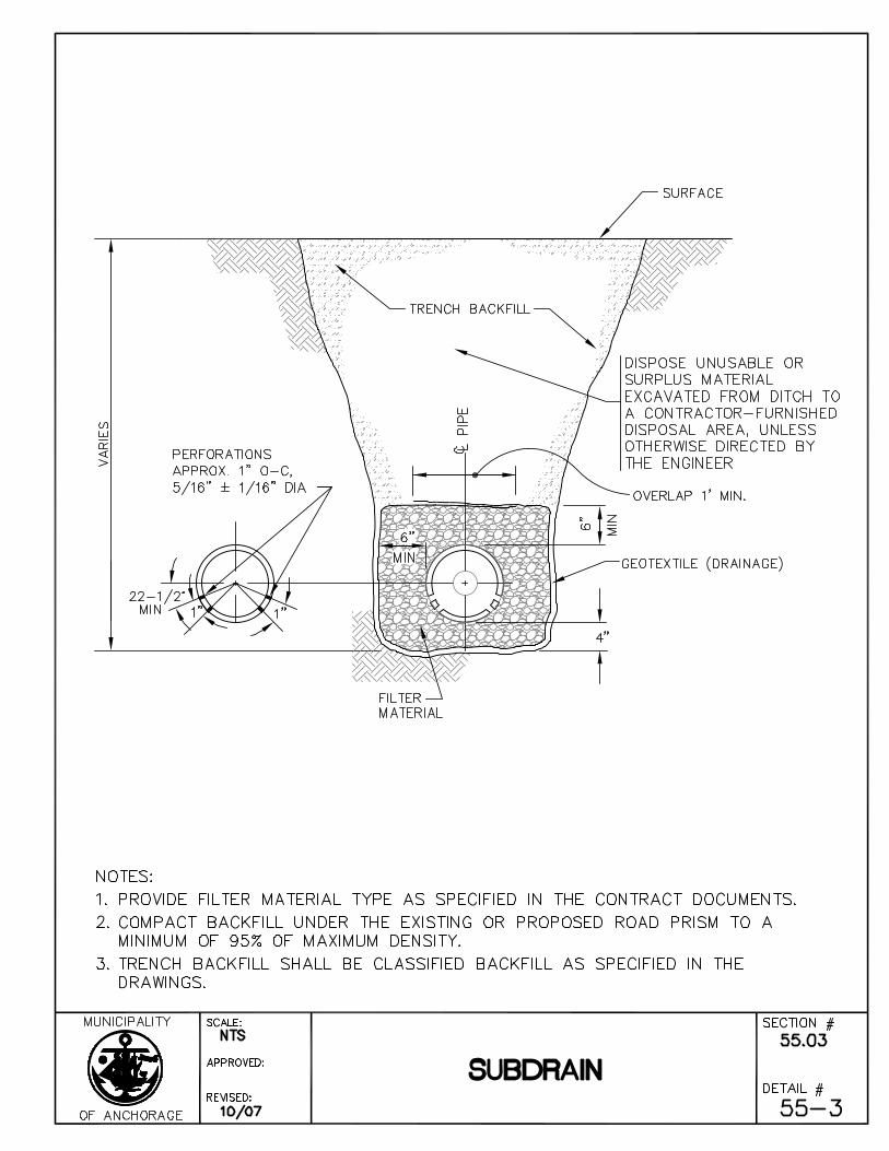
B. The Contractor shall use perforated steel, perforated aluminum or perforated aluminized coated corrugated metal pipe as noted. Corrugated metal pipe shall conform to the provisions of Section 55.02 - Furnish and Install Pipe. Perforations shall be located and sized in accordance with the requirements of AASHTO M-36. The top row of holes shall not be less than 22-1/2 degrees below the horizontal axis as shown on Standard Detail 55-3.
C. Corrugated Polyethylene Pipe (CPEP) shall conform to the provisions of Section 55.02 - Furnish and Install Pipe. Size and locate perforations in accordance with the requirements of AASHTO M252. Cleanly cut perforations so as not to restrict the inflow of water, and uniformly space along the length and circumference of the pipe. Contractor shall locate the top row of holes not less than 22 1/2º below the horizontal axis as shown on Standard Detail 55-3. Center perforations in the corrugation valleys. Provide water inlet area not less than a minimum of one square inch per linear foot of pipe. Perforations may be slots or holes. Slots shall be a maximum of one-tenth inch (1/10") wide. Holes shall not exceed three-sixteenth inch (3/16") diameter.
D. Geotextile fabric shall conform to Division 20, Section 20.25 – Geotextile Fabric, and shall be non-woven, pervious drainage material.
Article 3.3 Construction
Refer to Standard Detail 55-3 for construction of subdrains. Each phase of construction shall be accomplished in accordance with the applicable sections of these Specifications. Excavation and backfill for furnishing and installing of subdrains shall be in accordance with Division 20, Section 20.13 - Trench Excavation and Backfill. Furnishing and installing subdrains shall be in accordance with Section 55.02 - Furnish and Install Pipe. Furnish filter material in accordance with Division 20, Section 20.17 - Furnish Filter Material.
Article 3.4 Measurement
Measurement for all sizes of pipe shall be based on the horizontal distances and shall be from center to center of manholes, from the center of manholes to center of catch basins, from center of manholes to center of cleanout wye, and from center of manhole to end of pipe including flared end sections. Measurement includes: Furnishing, Installing, and
Page 15 Standard Construction Specifications
Division 55 – Storm Drain Systems Revised 11/08
Televising Pipe; Furnishing Filter Material; and, if applicable per Contract Documents, Furnishing and Installing Geotextile Fabric.
Article 3.5 Basis of Payment
Payment for this Work shall be in accordance with Division 10, Section 10.07 - Measurement and Payment, and shall include full payment for all Work described in this Section including furnishing and installing pipe, furnishing and placing filter material and, when required by the Contract Documents, furnishing and installing Geotextile Fabric.
Payment shall be made under the following units:
ITEM UNIT
Furnish & Install Subdrain (Size, Type, Class, Material, and Gauge of Pipe, and Type of Filter Material) Linear Foot
Furnish & Install Subdrain with Geotextile (Size, Type, Class, Material, and/or Gauge of Pipe, Type of Filter Material, and Type of Geotextile Fabric) Linear Foot
Page 16 Standard Construction Specifications
Division 55 – Storm Drain Systems Revised 11/08
SECTION 55.04 CONNECTIONS TO EXISTING MANHOLES OR CATCH BASINS
Article 4.1 General
The Work under this Section consists of the performance of all operations pertaining to the construction required for connections to existing manholes or catch basins.
Article 4.2 Construction
Excavation and backfill for connections to existing manholes or catch basins shall be in accordance with Division 20, Section 20.13 - Trench Excavation and Backfill.
Connections to existing manholes or catch basins shall be made in a workmanlike manner. The invert shall be brought into the existing manhole at the elevation shown on the Drawings. The downstream pipe in manholes shall be screened to prevent entry of mortar or other debris from entering the system.
After connection is made to a storm drain manhole and the mortar holding the pipe in place has set, cut the pipe off evenly so that no more than two inches (2") of pipe protrudes into the manhole and any screening shall be removed.
Article 4.3 Measurement
Connection to existing manholes shall be measured as complete units in place.
Article 4.4 Basis of Payment
Payment for this Work shall be in accordance with Division 10, Section 10.07 - Measurement and Payment, and shall include full payment for all Work described in this Section.
Payment shall be made on the following basis:
ITEM UNIT
Connect to Existing Storm Drain Manhole Each
Connect to Existing Storm Drain Catch Basin Each
Page 17 Standard Construction Specifications
Division 55 – Storm Drain Systems Revised 11/08
SECTION 55.05 MANHOLES AND CATCH BASIN MANHOLES
Article 5.1 General
The Work under this Section consists of the performance of all Work required for the construction of storm drain manholes and catch basin manholes complete with frames and covers.
Article 5.2 Material
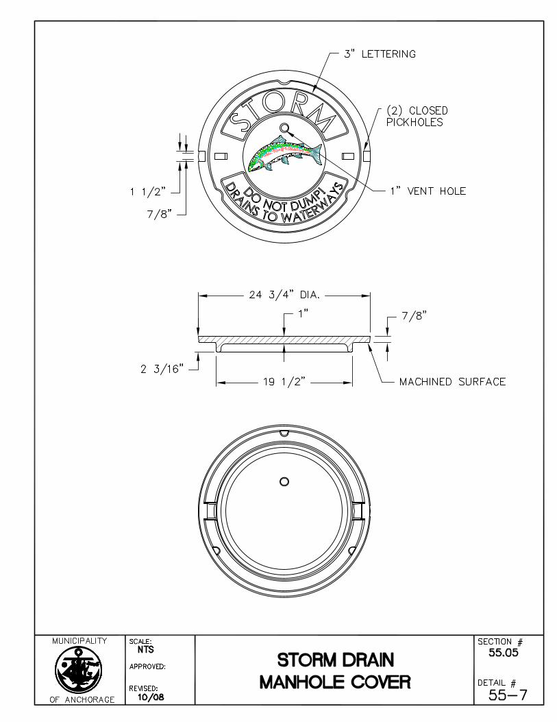
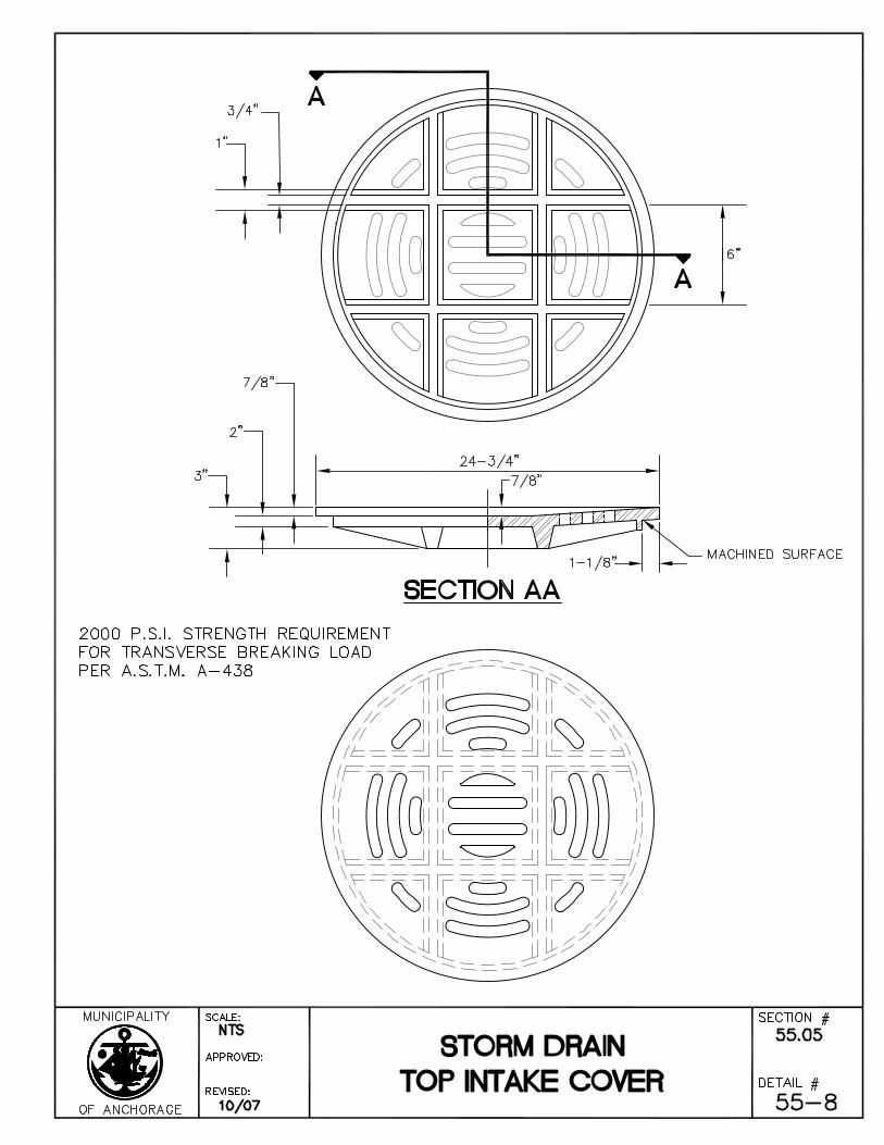
A. Frames and Covers
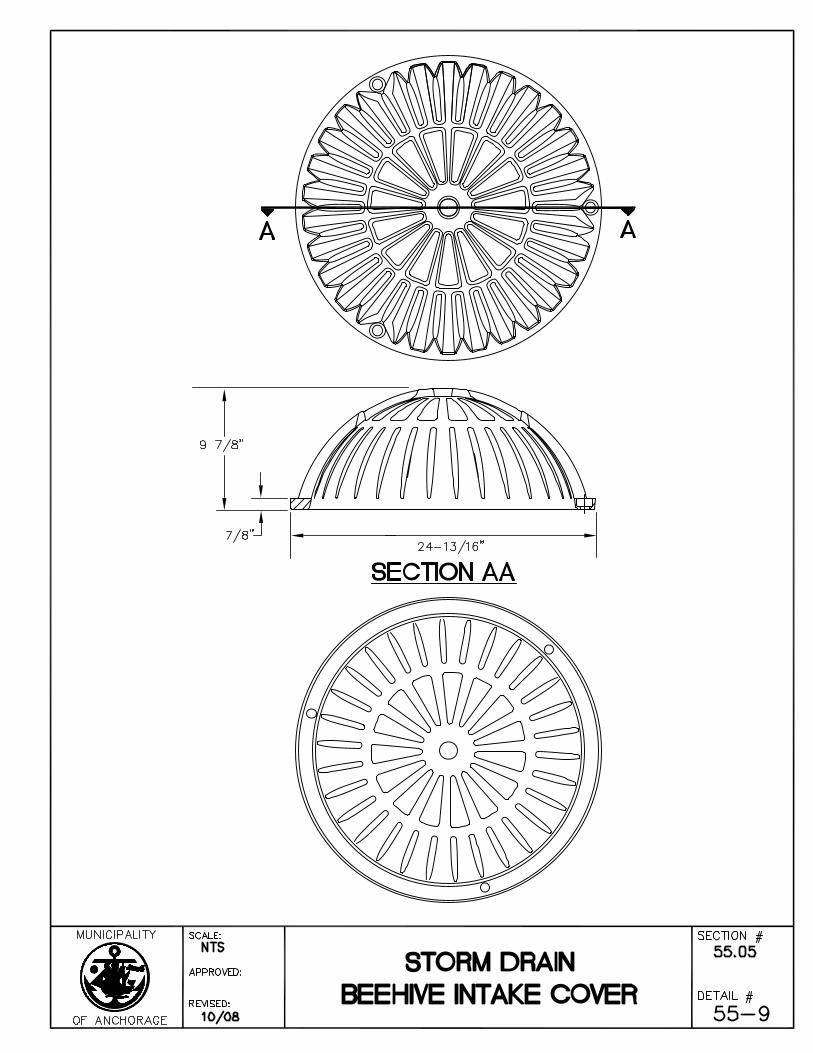
The requirement for tensile strength of the gray cast iron shall conform to the requirements of AASHTO M-306. Manhole frames, covers, and grates shall be furnished with machined horizontal bearing surfaces and shall conform to the Standard Details. The cover or grate shall not rock when rotated to any position in the frame. Catch basin manhole castings shall conform to the Standard Details.
Gray iron castings shall have appropriate certifications and be individually marked in accordance with the requirements of AASHTO M-306. Castings which do not possess appropriate AASHTO M-306 certifications and markings shall be replaced by the Contractor at no expense to the Owner.
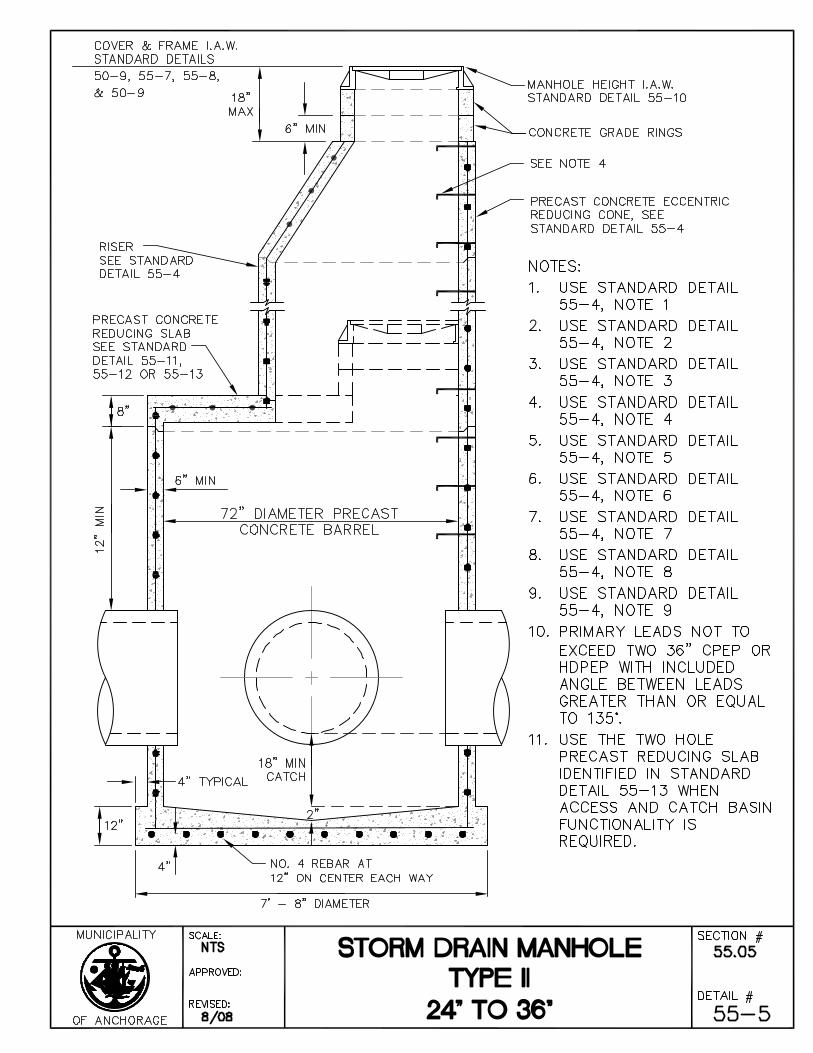
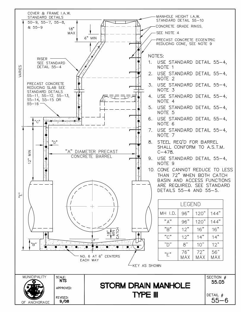
B. Reinforced Concrete Manholes
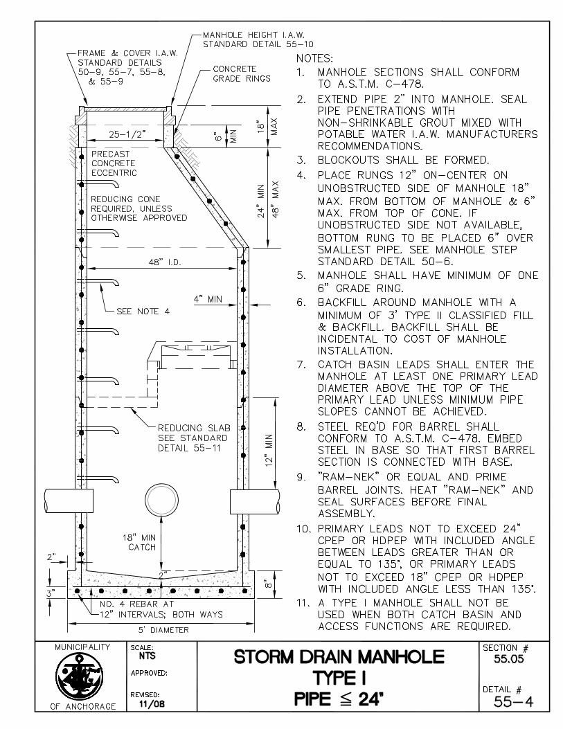
Material used in the construction of reinforced concrete manholes shall conform to the requirements of ASTM C-478 and the Standard Details. Cones shall be eccentric unless otherwise approved. Forty-eight inch (48") reinforced concrete pipe may be used for manhole riser sections as an alternate. This pipe shall conform to the requirements of ASTM C-76 with a minimum thickness of five inches (5").
Each precast concrete barrel section and eccentric cone shall be set and sealed by use of a pre-molded plastic gasket pipe joint sealer as manufactured by Henry Co, Ram-Nek Sealant Division or equal and installed to the manufacturer’s specification and meets AASHTO M-198, ASTM C990 or Federal Specification SS-S-210.
Cement for mortar used in the construction of manholes shall conform to the requirements of ASTM C-150, Type II. Sand shall conform to the requirements of AASHTO M-45. The mortar shall be composed of one (1) part cement and three (3) parts sand. The joints shall be constructed so as to produce a smooth, regular, watertight surface. Water shall be added in minimum amounts to provide plasticity in placing the mortar. Each concrete adjusting ring and manhole cover/frame that falls outside of a paved road section shall be set and sealed by a pre-molded plastic gasket sealer. Each concrete adjusting ring and manhole cover/frame that falls in a paved road section/sidewalk shall be set in a full bed of mortar.
Page 18 Standard Construction Specifications
Division 55 – Storm Drain Systems Revised 11/08
Refer to Division 30, Section 30.01, Article 1.6 - Mix Requirements for Classes of Concrete, for Specifications pertaining to Class A-3 concrete as required in forming manhole inverts.
Reinforcement steel shall conform to the requirements of ASTM A-185, ASTM A-615, Grade 60 steel, or better, and the Standard Details.
Article 5.3 Construction
A. General
Excavation and backfill for the construction of storm drain manholes and catch basin manholes shall be in accordance with Division 20, Section 20.13 - Trench Excavation and Backfill.
All portions of the manholes must be approved by the Engineer prior to installation in the storm drain system. The Contractor shall provide timely notice (at least two Working days in advance of casting) to allow time for the Engineer to arrange for necessary inspections. Installation of manhole sections without the Engineer's written approval shall not be allowed. This approval does not relieve the Contractor of the responsibility for protection of manholes against damage during handling and installation.
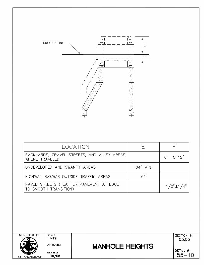
The manhole frames and covers shall be brought to grades shown on the Drawings unless otherwise approved by the Engineer. Manhole rings shall be set in a full bed of mortar and made secure. Grade adjustment rings must be set centered over the manhole and catch basin cone or lid opening with no lateral offset. No more than a one-quarter inch (1/4”) lateral offset is permitted between grade adjustment rings. Total cumulative offset between grade adjustment rings shall not exceed one-half inch (1/2”). Manhole rings and catch basin frames shall be set centered on the opening with a maximum lateral offset of one-half inch (1/2”) permitted.
Manholes shall be installed at the location shown on the Drawings and primary leads shall enter radially at the invert elevations specified. The base section shall be set plumb on a prepared surface. Prepared surface shall be compacted to a minimum of ninety-five percent (95%) of maximum density.
In the case of precast manhole barrel sections where holes need to be bored to provide for the storm drain pipe, the diameter of the bore shall not exceed the outside diameter of the storm drain pipe plus one and one-half inches (1.5”).
Where indicated on the Drawings, a stub shall be provided for future connections to the manhole. The stub shall be sized and positioned as indicated. The end of the stub shall be stopped with a wooden plug, concrete biscuit, or other adequate methods to prevent water, earth or other substances from entering the pipe. Manholes up to twelve feet (12’) in depth shall have ten foot (10’) stubouts; over twelve feet (12’) in depth shall have twenty foot (20’) stubouts.
Page 19 Standard Construction Specifications
Division 55 – Storm Drain Systems Revised 11/08
In the case of poured-in-place manhole construction, if the Contractor elects to accomplish the manhole construction utilizing more than one continuous concrete pour, a keyed construction joint shall be used. These manholes shall have poured-in-place bases. Precast concrete barrel sections shall be set and sealed with premolded plastic gasket. Premolded plastic gaskets for sealing pre-cast concrete barrel sections for manholes shall meet AASHTO M-198, ASTM C-990, or Federal Specification SS-S-210 and shall be installed in accordance with the manufacturer's recommendations. Gaskets shall be trimmed on the inside of the manhole to prevent the excess gasket material from entering the storm drain lines.
B. Storm Drain Manholes and Catch Basin Manholes
Contractor shall construct storm drain manholes in accordance with the Drawings and Standard Details. In the invert of manholes, Contractor shall construct a catch of eighteen inches (18”) minimum depth, unless otherwise specified.
After connecting the storm drain pipe to reinforced concrete manhole or catch basin, seal annular space around pipe penetrations with cement mortar, or an approved equal. Cement mortar shall conform to the requirements of ASTM C-150, Type II. After the mortar has firmly set, Contractor shall cut the pipe evenly so that no more than two inches (2”) of the pipe protrudes into the manhole.
Article 5.4 Measurement
Manholes and catch basin manholes shall be measured as units complete in place. Depth of manholes and catch basin manholes shall be based upon a measurement to the nearest foot from top of casting to the top of the base slab. Standard depths for manholes and catch basin manholes shall be constructed in accordance with the Standard Details and designated as to type.
TYPE STANDARD DEPTH
Type I, II, III twelve feet (12’)
All depths over the specified standard depth shall be paid for under the bid item "Additional Depth to Manhole" as defined below:
Additional Depth for Manholes:
This item consists of the construction of additional depth to manholes over and above the twelve foot (12') depth specified below.
Additional depth to manholes and catch basin manholes shall be complete in place.
Page 20 Standard Construction Specifications
Division 55 – Storm Drain Systems Revised 11/08
Article 5.5 Basis of Payment
Payment for this Work shall be in accordance with Division 10, Section 10.07 - Measurement and Payment, and shall include full payment for all Work described in this Section.
Payment shall be made on the following basis:
ITEM UNIT
Construct (Type, Diameter*) Manhole Each
Construct (Type) Catch Basin Manhole Each
Additional Depth to (Type) Manhole Linear Foot
* For Type III manholes, include the diameter in the descriptor for the appropriate pay item.
Page 21 Standard Construction Specifications
Division 55 – Storm Drain Systems Revised 11/08
SECTION 55.06 WATERTIGHT MANHOLE FRAMES AND COVER
Article 6.1 General
The Work under this Section consists of the performance of all Work required for the construction of watertight manhole frames and covers.
Article 6.2 Material
Watertight frames and covers for manholes and similar appurtenances shall be of cast iron and conform to the dimension shown in the Standard Details. The requirement for tensile strength of the gray iron shall be 30,000 PSI minimum in accordance with the requirements of ASTM A-48 and the requirement for transverse breaking load shall be 2,000 pounds in accordance with the requirements of ASTM A-438. Contact surfaces between frames and covers shall be machined to provide a uniform contact surface. Manhole covers shall have identification letters as shown on the Standard Details.
Article 6.3 Construction
Provide watertight Manhole Frames and Covers as indicated on the Drawings and in accordance with the Standard Details.
Article 6.4 Measurement
Watertight manhole frames and covers shall be measured as complete units in place.
Article 6.5 Basis of Payment
Payment for this Work shall be in accordance with Division 10, Section 10.07 - Measurement and Payment, and shall include full payment for all Work described in this Section.
Payment is to be made only for the additional cost of furnishing and installing the watertight frame and cover which exceeds the cost of the standard frame and cover included in the completed manhole unit price.
Payment shall be made under the following unit:
ITEM UNIT
Additional Cost of Watertight Manhole Frame and Cover Each
Page 22 Standard Construction Specifications
Division 55 – Storm Drain Systems Revised 11/08
SECTION 55.07 ADJUST STORM DRAIN MANHOLE CONE TO FINISH GRADE
Article 7.1 General
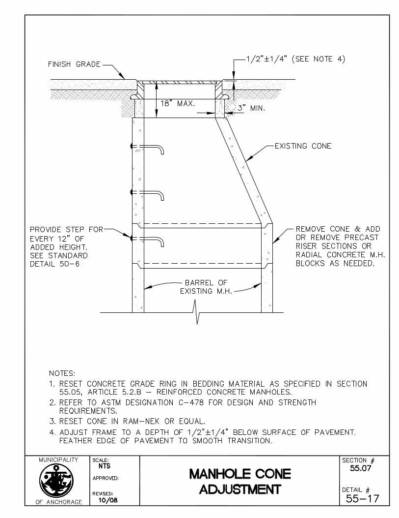
The Work under this Section consists of providing all operations pertaining to the adjustment of existing manhole cones to finish grade. All broken and/or missing manhole components are to be replaced with new materials furnished and installed by the Contractor.
Article 7.2 Material
All materials used in the adjustment of manhole cones including mortar, steps, barrel sections, bIackpremolded plastic gaskets, etc., shall conform to the requirements for manholes as outlined in Section 55.05 - Manholes and Catch Basin Manholes. Radial concrete manhole blocks may be used for upward adjustments in certain cases if approved by the Engineer.
Article 7.3 Construction
The Contractor shall remove the existing cone and add to or remove portions of the barrel of each manhole requiring a cone adjustment. Each precast concrete barrel and cone section shall be set upon and sealed with a premolded plastic gasket which shall meet AASHTO M-198, ASTM C990, or Federal Specification SS-SS-210. Any damage to manholes resulting from construction under this Contract shall be repaired or the damaged portion replaced at the Contractor’s expense. All inverts, benchwalls, and/or catch areas shall be left clean and free from any foreign materials.
Contractor shall adjust the manhole cone to finish grade prior to placement of asphalt pavement. New asphalt shall not be cut for adjustments.
Article 7.4 Measurement
Manhole cone adjustments shall be measured as units, complete in place.
Page 23 Standard Construction Specifications
Division 55 – Storm Drain Systems Revised 11/08
Article 7.5 Basis of Payment
Payment for this Work shall be in accordance with Division 10, Section 10.07 - Measurement and Payment, and shall include full payment for all Work described in this Section.
Payment for cone adjustments shall include compensation for changes in height per the applicable Standard Details, unless otherwise directed by the Engineer. In no case will payment for both ring and cone adjustments be made for the same manhole. Any adjustments requiring cutting of new asphalt shall not be paid and shall be deducted from the plan quantity.
Payment shall be made under the following unit:
ITEM UNIT
Adjust Storm Drain Manhole Cone Each
Page 24 Standard Construction Specifications
Division 55 – Storm Drain Systems Revised 11/08
SECTION 55.08 ADJUST STORM DRAIN MANHOLE RING TO FINISH GRADE
Article 8.1 General
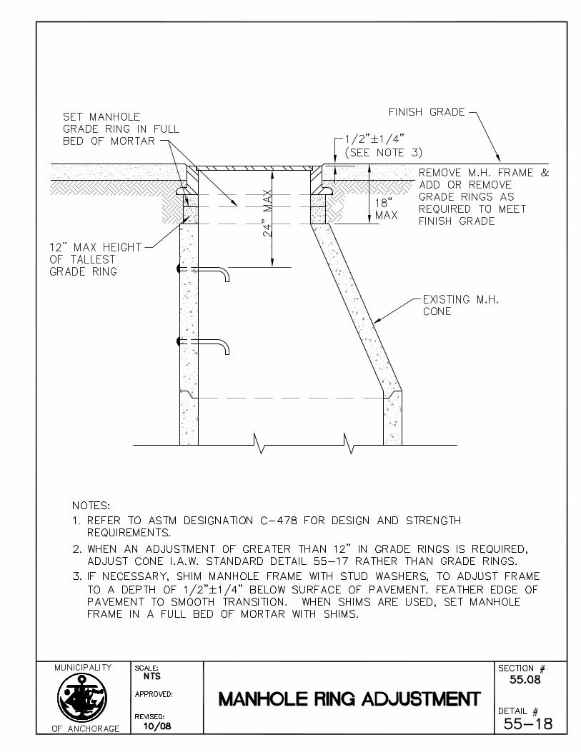
The Work under this Section consists of providing all operations pertaining to the adjustment of existing manhole rings to finish grade, All broken and/or missing manhole components are to be replaced with new materials furnished and installed by the Contractor in accordance with these Specifications.
Article 8.2 Material
All materials used in the adjustment of manhole rings shall conform to the requirements for manholes as outlined in Section 55.05 – Manholes and Catch Basin Manholes.
The Contractor may utilize Neenah R-1979 Series Manhole Adjusting Rings, or an approved equal, for adjusting the manhole to finished grade.
Article 8.3 Construction
The Contractor shall adjust the manhole rings in accordance with the applicable Standard Details. The Contractor shall set the adjusting rings in a bed of premolded plastic gasket material that meets AASHTO M-198, ASTM C990, or Federal Specification SS-S-210. The casting can be set in a bed of mortar with steel adjusting shims in the event the grade will not allow the premolded plastic gasket material. The steel shims shall be placed in four locations as a minimum and must be approved by the Engineer. Any damage to manholes resulting from construction under this Contract shall be repaired or the damaged portion replaced at the Contractor’s expense.
Grade adjustment rings must be set centered over the manhole and catch basin cone or lid opening with no lateral offset. No more than a one-quarter inch (1/4”) lateral offset is permitted between grade adjustment rings. Total cumulative offset between grade adjustment rings shall not exceed one-half inch (1/2”). Manhole rings and catch basin frames shall be set centered on the opening with a maximum lateral offset of one-have inch (1/2”) permitted.
Milling is an approved method of lowering the manhole grade. A horizontal milling process ware as the casting is milled to lower the top to meet the finish grade of the street. This method must be submitted to the Engineer for approval.
Contractor shall remove and replace pavement around the manhole prior to adjustment in such a way to minimize impact to the travel path of the roadway. Contractor shall either use infrared treatment to amalgamate old and new pavement or shall make the pavement cut in such a way to prevent a straight line patch from occurring perpendicular to the direction of travel. Pavement cuts shall be made in a diamond shape in relation to the travel path rather than a square shape.
Contractor shall adjust the manhole cone to finish grade prior to placement of asphalt pavement. New asphalt shall not be cut for adjustments.
Page 25 Standard Construction Specifications
Division 55 – Storm Drain Systems Revised 11/08
Article 8.4 Measurement
Manhole ring adjustments shall be measured as units, complete in place.
Article 8.5 Basis of Payment
Payment for this Work shall be in accordance with Division 10, Section 10.07 – Measurement and Payment, and shall include full payment for all Work described in this Section.
Payment for ring adjustment shall include full compensation for changes in height. In no case will payment for both ring and cone adjustments be made for the same manhole. Any adjustments requiring cutting of new asphalt shall not be paid and shall be deducted from the plan quantity.
Payment shall be made under the following unit:
ITEM UNIT
Adjust Storm Drain Manhole Ring Each
Page 26 Standard Construction Specifications
Division 55 – Storm Drain Systems Revised 11/08
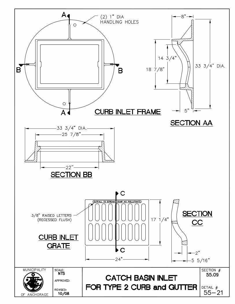
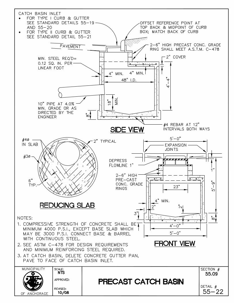
SECTION 55.09 CONSTRUCT CATCH BASIN
Article 9.1 General
The Work under this Section consists of the performance of all operations pertaining to the construction and installation of catch basins.
Article 9.2 Material
Materials used in the construction of catch basins shall conform to the requirements of ASTM C-478 and the Standard Details.
Cement for mortar used in the construction of catch basins shall conform with the requirements of ASTM C-150, Type II. Sand shall conform with the requirements of AASHTO M-45.
Article 9.3 Construction
Excavation and backfill for furnishing and installing of catch basin shall be in accordance with Division 20, Section 20.13 - Trench Excavation and Backfill.
After the mortar has set firmly, the pipe is to be cut off evenly so that not more than two inches (2") of the pipe protrudes into the catch basin.
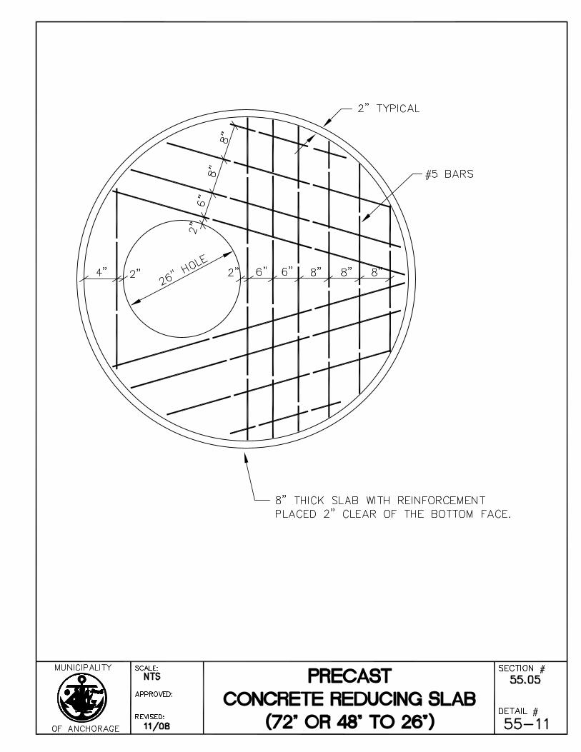
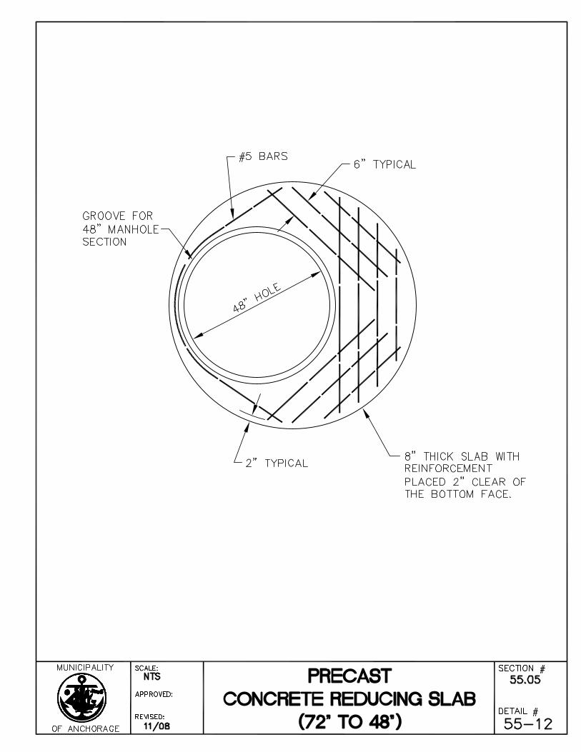
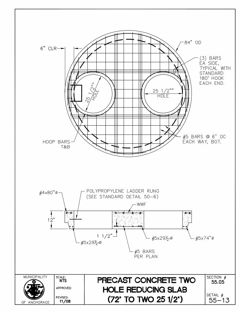
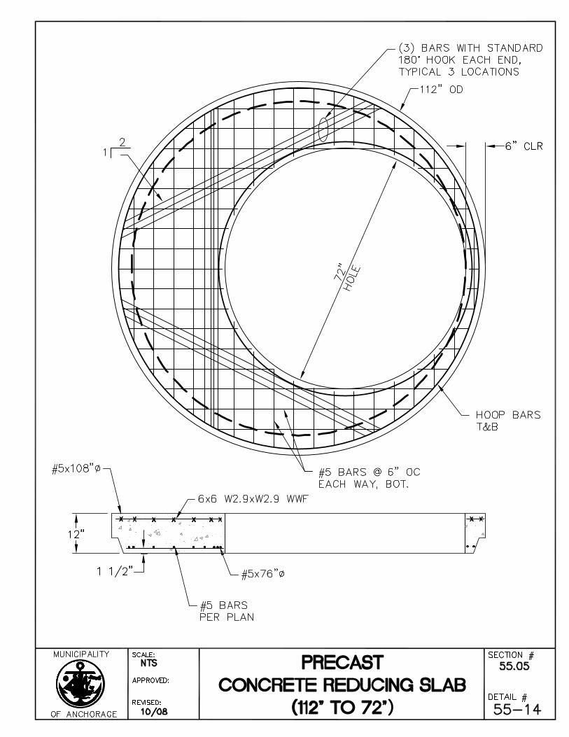
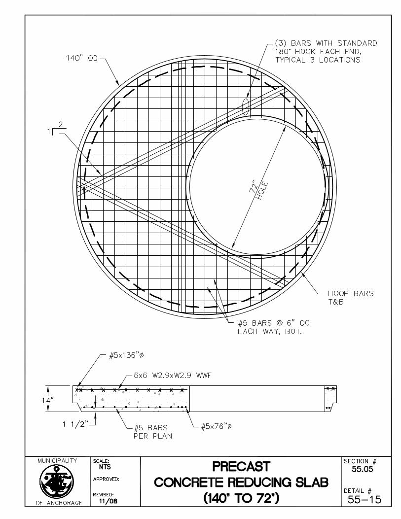
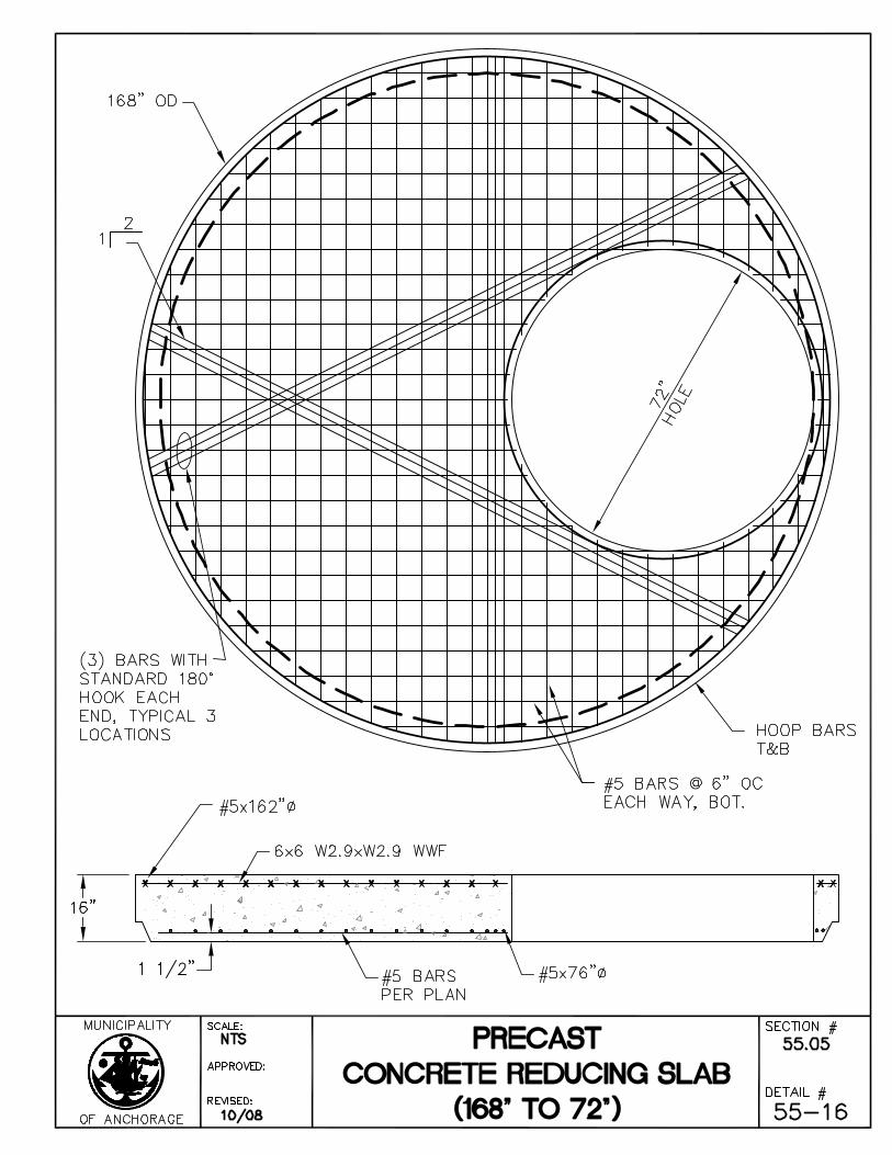
Reducing slab shall be set and sealed by a pre-molded plastic gasket joint sealer as manufactured by Henry Co., Ram-Nek Sealant Division or equal and installed to the manufacturer’s specification. Plastic gasket joint sealers shall meet AASHTO M-198, ASTM C-990, or Federal Specifications SS-S-210.
Contractor shall bring catch basin rings and covers to the grades shown on the Drawings. Grade stakes defining the elevation of the casting, and hub stakes with tacks to define the line for the curb face shall be set by the Contractor. The Contractor may accomplish final setting of the casting by wedging it up with masonry material as approved by the Engineer. The casting shall then be set in a full bed of mortar and made secure.
Mortar used in the construction of catch basins shall be composed of one (1) part cement and three (3) parts sand. All joints and connections are to be mortared. The joints shall be made so as to produce a smooth, regular, watertight surface. Water shall be added in minimum amounts to provide plasticity in placing the mortar.
Contractor shall use Class A-3 concrete, as defined in Division 30, Section 30.01, Article 1.6 - Mix Requirements For Classes of Concrete, in the formation of catch basin base slabs.
Article 9.4 Measurement
Catch Basins shall be measured as units complete in place.
Page 27 Standard Construction Specifications
Division 55 – Storm Drain Systems Revised 11/08
Article 9.5 Basis of Payment
Payment for this Work shall be in accordance with Division 10, Section 10.07 - Measurement and Payment, and shall include full payment for all Work described in this Section.
Payment shall be made on the following basis:
ITEM UNIT
Construct Catch Basin Each
Page 28 Standard Construction Specifications
Division 55 – Storm Drain Systems Revised 11/08
SECTION 55.10 RELOCATE CATCH BASIN OR CATCH BASIN MANHOLE
Article 10.1 General
The Work under this Section consists of providing all operations pertaining to relocating of existing catch basin or catch basin manholes.
Article 10.2 Material
All materials used in relocation of catch basins or catch basin manholes shall conform to the requirements for catch basins as outlined in Section 55.05 - Manholes and Catch Basin Manholes, and Section 55.09 - Construct Catch Basin.
Article 10.3 Construction
The Contractor shall note the fact that he may be required to relocate more than one type of catch basin or catch basin manhole under this Contract. All excavation, trenching and backfill necessary for the removal and relocation shall be considered incidental to this item. The Contractor shall backfill the excavation with suitable, non-frost-susceptible material and compact it to not less than ninety-five percent (95%) of maximum density as directed by the Engineer. If additional material is required for backfill it will be paid for under the item "Furnish Trench Backfill." Existing leads may require relocation up to a maximum length of fifteen feet (15') to provide proper alignment. Such relocation shall be considered incidental to this Item. Relocation of existing pipe leads and any additional pipe leads shall be incidental Work. Pipe used shall be the same size and type as the existing leads. The relocated catch basin or catch basin manholes shall be adjusted to finish grade as directed by the Engineer.
Article 10.4 Measurement
Relocation of catch basins or catch basin manholes will be measured on a basis of units complete in place at the new location and accepted by the Engineer.
Article 10.5 Basis of Payment
Payment for this Work shall be in accordance with Division 10, Section 10.07 - Measurement and Payment, and shall include full payment for all Work described in this Section.
Payment shall be made under the following units:
ITEM UNIT
Relocate Catch Basin Each
Relocate Catch Basin Manhole Each
Page 29 Standard Construction Specifications
Division 55 – Storm Drain Systems Revised 11/08
SECTION 55.11 REMOVE MANHOLE OR CATCH BASIN
Article 11.1 General
The Work under this Section consists of providing all operations pertaining to the removal and disposal or salvage of existing manholes.
Article 11.2 Construction
Salvaged materials shall be removed in a workman-like manner and delivered to a site as directed by the Engineer. Non-salvageable materials shall be removed to a Contractor-provided disposal site.
Any excavation required in the removal shall be considered incidental to this item. The Contractor shall backfill the excavation with a suitable, non-frost susceptible material and compact it to not less than ninety-five percent (95%) of maximum density as directed by the Engineer. If additional material is required for backfill, it will be paid for under the Item "Furnish Trench Backfill." Existing pipes shall be suitably plugged and abandoned unless otherwise noted.
Article 11.3 Measurement
Removal of existing manholes or catch basins will be measured as units.
Article 11.4 Basis of Payment
Payment for this Work shall be in accordance with Division 10, Section 10.07 - Measurement and Payment, and shall include full payment for all Work described in this Section.
Payment shall be made under the following units:
ITEM UNIT
Remove Manhole Each
Remove Catch Basin Each
Page 30 Standard Construction Specifications
Division 55 – Storm Drain Systems Revised 11/08
SECTION 55.12 ADJUST CATCH BASIN TO FINISH GRADE
Article 12.1 General
The Work under this Section consists of providing all operations pertaining to the adjustment of existing catch basins to finish grade.
Article 12.2 Material
All materials used in the adjustment of catch basins shall conform to the requirements for catch basins as outlined in Section 55.09 - Construct Catch Basin.
Article 12.3 Construction
Rotational as well as vertical displacement of the catch basin top and casting might occur. All adjustments will be accomplished as directed by the Engineer. Any damage to catch basins resulting from construction under this Contract shall be repaired or the damaged portion replaced at the Contractor's expense.
Grade adjustment rings must be set centered over the catch basin cone or lid opening with no lateral offset. No more than a one-quarter inch (1/4”) lateral offset is permitted between grade adjustment rings. Total cumulative offset between grade adjustment rings shall not exceed one-half inch (1/2”). Catch basin frames shall be set centered on the opening with a maximum lateral offset of one-have inch (1/2”) permitted.
Article 12.4 Measurement
Catch basin adjustments shall be measured as units, complete in place.
Article 12.5 Basis of Payment
Payment for this Work shall be in accordance with Division 10, Section 10.07 - Measurement and Payment, and shall include full payment for all Work described in this Section.
Payment shall be made under the following unit.
ITEM UNIT
Adjust Catch Basin to Finish Grade Each
Page 31 Standard Construction Specifications
Division 55 – Storm Drain Systems Revised 11/08
SECTION 55.13 ABANDON CATCH BASIN LEAD
Article 13.1 General
The Work under this Section consists of performing all operations pertaining to the abandonment of catch basin leads. Catch basin leads to be abandoned may be crushed in place, filled with sand slurry, or removed, at Contractor's option and approval by the Engineer.
Article 13.2 Materials
Sand slurry shall consist of a mixture of water and sand with an approximate ratio of seven gallons of water per cubic foot of sand. Native materials that contain no lumps, frozen material, organic matter, or other deleterious material are acceptable for use in the slurry mixture.
Article 13.3 Construction
Contractor shall abandon all catch basin leads as shown on the Drawings. The opening in the storm drain manhole where the catch basin lead enters shall be plugged with concrete grout and the lead filled with sand slurry.
Where catch basin leads lie within trench excavation, as called for in the Drawings and Specifications, the leads shall be removed.
Article 13.4 Measurement
Abandonment of each catch basin lead shall be measured as a complete unit. This item will include materials, excavations, placement of materials, disposal of unusable materials, backfill, and incidental operations.
Article 13.5 Basis of Payment
Payment for this Work shall be in accordance with Division 10, Section 10.07 - Measurement and Payment, and shall include full payment for all Work described in this Section.
Payment shall be made under the following unit:
ITEM UNIT
Abandon Catch Basin Lead Each
Page 32 Standard Construction Specifications
Division 55 – Storm Drain Systems Revised 11/08
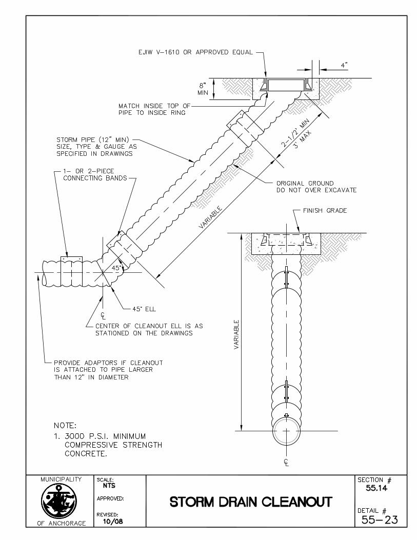
SECTION 55.14 CONSTRUCT STORM CLEANOUT
Article 14.1 General
The Work under this Section consists of the performance of all Work required for the construction and installation of storm drain cleanouts.
Article 14.2 Material
Materials used in the construction of storm drain cleanouts shall conform to the Standard Details.
Article 14.3 Measurement
Storm drain cleanouts shall be measured as units, complete in place.
Article 14.4 Basis of Payment
Payment for this Work shall be in accordance with Division 10, Section 10.07 - Measurement and Payment, and shall include full payment for all Work described in this Section.
Payment shall be made on the following basis:
ITEM UNIT
Construct Storm Drain Cleanout Each
Page 33 Standard Construction Specifications
Division 55 – Storm Drain Systems Revised 11/08
SECTION 55.15 ADJUST STORM CLEANOUT TO FINISH GRADE
Article 15.1 General
The Work under this Section consists of providing all operations pertaining to adjustment of existing cleanouts to finish grade. All broken and/or missing cleanout components are to be replaced with new materials furnished and installed by the Contractor in accordance with these Specifications.
Article 15.2 Material
All materials used in the adjustment of cleanouts shall conform to the requirements for cleanouts as outlined in Section 55.14 - Construct Storm Cleanout.
Article 15.3 Construction
The Contractor may be required to adjust more than one type of cleanout under this Contract. All adjustments will be accomplished as directed by the Engineer. Any damage to cleanouts resulting from construction under this Contract shall be repaired or the damaged portion replaced at the Contractor's expense.
Article 15.4 Measurement
Cleanout adjustments will be measured per unit, complete in place.
Article 15.5 Basis of Payment
Payment for this Work shall be in accordance with Division 10, Section 10.07 - Measurement and Payment, and shall include full payment for all Work described in this Section.
Payment shall be made under the following unit:
ITEM UNIT
Adjust Storm Cleanout to Finish Grade Each
Page 34 Standard Construction Specifications
Division 55 – Storm Drain Systems Revised 11/08
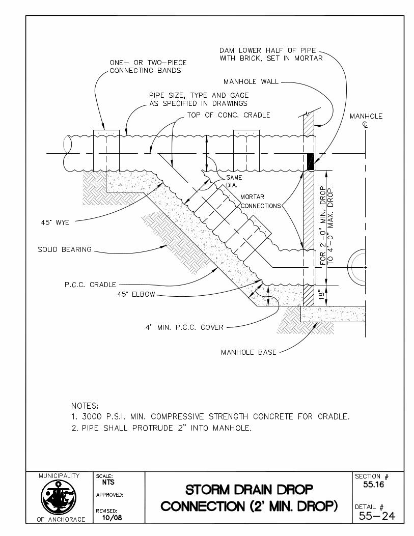
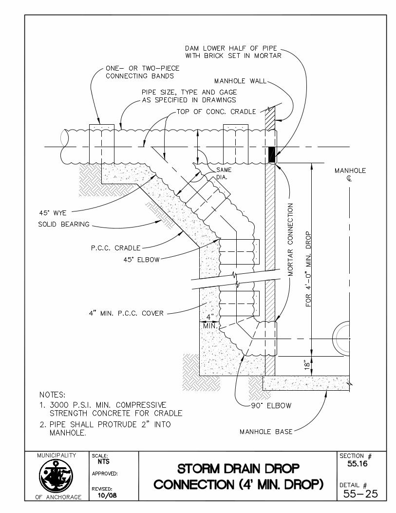
SECTION 55.16 CONSTRUCT DROP CONNECTION
Article 16.1 General
The Work under this Section consists of the performance of all Work required for the construction and installation of storm drain drop connections to manholes.
Article 16.2 Material
Pipe and fittings used in the construction of drop connections for storm drain shall conform to the requirements of Section 55.02 - Furnish and Install Pipe and the Standard Details.
Article 16.3 Construction
Excavation and backfill for the construction of drop sewer connection to manhole shall be in accordance with Division 20, Section 20.13 - Trench Excavation and Backfill.
Over-excavation under drop connection shall require compaction of not less than ninety-five percent (95%) of the maximum density prior to installation of the pipe and fittings, or the concrete cradle.
Refer to Division 30, Section 30.01, Article 1.6 - Mix Requirements for Classes of Concrete for specifications pertaining to Class A-3 concrete.
Article 16.4 Measurement
Storm drain drop connections shall be measured as units, complete in place.
Article 16.5 Basis of Payment
Payment for this Work shall be in accordance with Division 10, Section 10.07 - Measurement and Payment, and shall include full payment for all Work described in this Section.
Payment shall be made on the following basis:
ITEM UNIT
Construct Drop Storm Drain Connection (Detail #) Each
Page 35 Standard Construction Specifications
Division 55 – Storm Drain Systems Revised 11/08
SECTION 55.17 FLUME DOWNDRAIN
Article 17.1 General
The Work under this Section consists of performing all operations pertaining to furnishing and installing flume downdrain(s) with anchor assemblies at locations shown on the Drawings.
Article 17.2 Materials
All material utilized in the fabrication of the galvanized metal flume downdrain(s) shall conform to Section 55.02 - Furnish and Install Pipe with a minimum sheet thickness of six-hundredths inches (0.060”).
Article 17.3 Construction
The flume downdrain(s) shall be fabricated in accordance with the details and dimensions shown on the Drawings. No dissimilar metal shall be allowed at any installation. Anchor assemblies shown on the Drawings may be used with an aluminum installation provided the anchor assemblies are electrically insulated. All flume sections shall be connected together and to the existing pipe by means of galvanized bolts as indicated on the Drawings.
Article 17.4 Measurement
Measurement shall be based on the horizontal length of flume downdrain measured from the top end of the flume downdrain to end of flared or half-round metal pipe modified end section complete in place with anchors properly placed in the ground and bolted to the flume downdrain pipe.
Article 17.5 Basis of Payment
Payment for this Work shall be in accordance with Division 10, Section 10.07 - Measurement and Payment, and shall include full payment for all Work described in this Section.
Payment shall be made under the following unit:
ITEM UNIT
Furnish and Install Flume Downdrain (Size) Linear Foot
Page 36 Standard Construction Specifications
Division 55 – Storm Drain Systems Revised 11/08
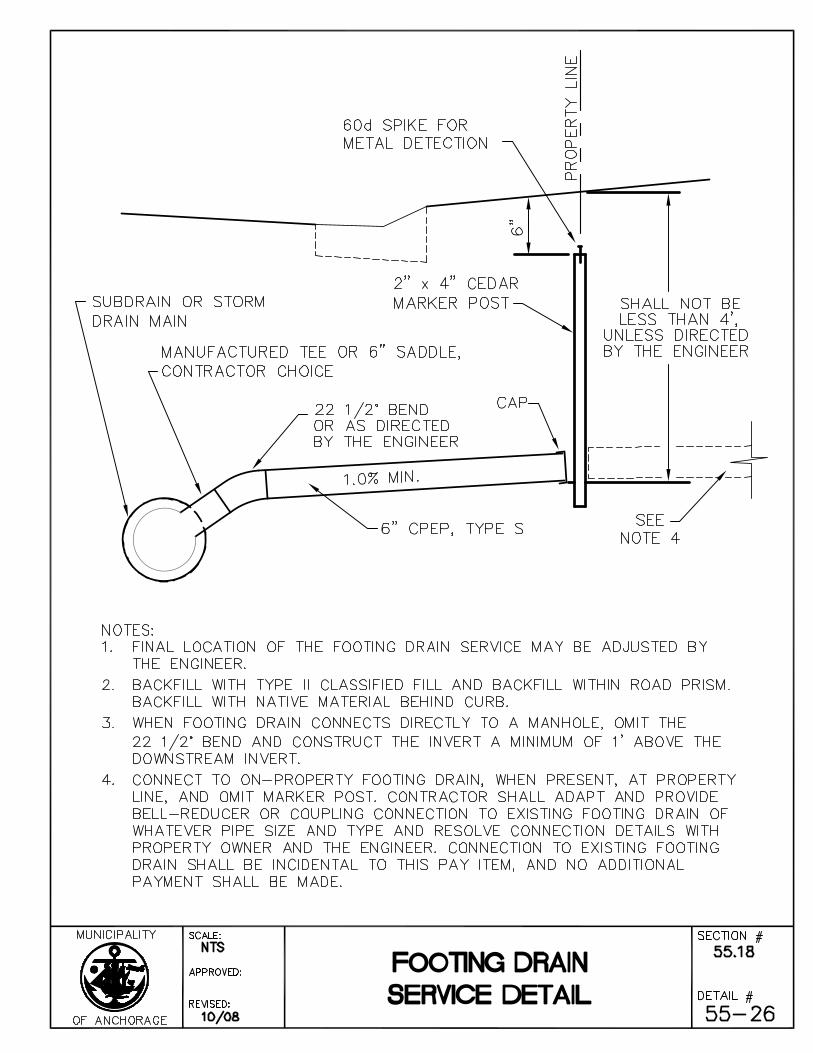
SECTION 55.18 FOOTING DRAIN SERVICES
Article 18.1 General
The Work under this section includes all material, labor, and equipment necessary for the disconnection and reconnection of six inch (6”) footing drain services to the storm drain system.
Article 18.2 Material
Provide six inch (6”) CPEP (Type S) Pipe and Filter Material (Type B).
Connect footing drain services to the storm drain with a six inch (6”) saddle of a type recommended by the pipe manufacturer.
Article 18.3 Construction
Excavation and backfill for the construction of footing drain services is incidental to the bid item reconnect footing drain services. The number and approximate location of footing drain services are shown on the Drawings.
Article 18.4 Measurement
Footing drain services is measured as units, complete in place.
The Work under this Section includes all materials, equipment, and work required to disconnect and reconnect the footing drain services as indicated on the Drawings and in accordance with this Division and Division 20 – Earthwork. Such materials, equipment, and Work are incidental and no additional payment is made for the following:
Trench Excavation and Backfill, Unusable or Surplus Excavation, Disposal of Unsuitable or Surplus Material, Usable Excavation, Type B Filter Material, Furnish and Install Subdrain Pipe, Mechanical Compaction, Type II Trench Backfill, Shoring, Sheeting, and Bracing, Portable and Steel Shield, and Canousa Wrap.
Article 18.5 Basis of Payment
Payment for this Work shall be in accordance with Division 10, Section 10.07 - Measurement and Payment, and shall include full payment for all Work described in this Section.
ITEM UNIT
Reconnect Footing Drain Service Each
Page 37 Standard Construction Specifications
Division 55 – Storm Drain Systems Revised 11/08
SECTION 55.19 CONSTRUCT OPEN DITCH
Article 19.1 General
The Work under this Section consists of the performance of all Work required for the excavation, embankment and spreading of material necessary to construct an open ditch.
Article 19.2 Construction
A. Excavation
Excavation shall be to the grade and ditch cross section shown on the Drawings. The final ditch shall have no projections of roots, stumps, rock or similar matter. Material hauled from the job site for disposal shall be paid for under Division 20, Section 20.27 – Disposal of Unusable or Surplus Material.
B. Embankment
Embankment shall be to the shape and at the location shown on the Drawing. The type of material utilized to construct ditch banks and dikes shall be as noted on the Drawing, or as approved by the Engineer. If additional material is required for embankment, it will be paid for under Division 20 - Earthwork.
C. Cleanup
The Contractor shall maintain the ditch and keep it open and free from all debris, as directed by the Engineer until final acceptance.
Article 19.3 Measurement
Measurement for open ditch construction shall be per linear foot along the slope of the ditch.
Article 19.4 Basis of Payment
Payment for this Work shall be in accordance with Division 10, Section 10.07 - Measurement and Payment, and shall include full payment for all Work described in this Section.
Payment shall be made on the following basis:
ITEM UNIT
Construct Open Ditch Linear Foot
Page 38 Standard Construction Specifications
Division 55 – Storm Drain Systems Revised 11/08
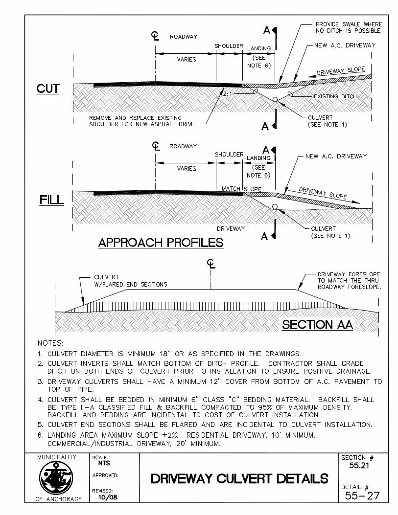
SECTION 55.20 CULVERT
Article 20.1 General
The Work under this Section consists of the performance of all materials and operations required to furnish and install culverts.
Article 20.2 Construction
Excavation and backfill for furnishing and installing of culverts shall be in accordance with Division 20, Section 20.13 - Trench Excavation and Backfill.
The Contractor shall furnish and install culverts as shown on the Drawings. The pipe shall be installed to the alignment and grades as required by the Drawings. Pipe materials shall meet the Specifications included in Section 55.01 - General and Section 55.02 - Furnish and Install Pipe, of this Division. The pipe shall be installed so that there is a minimum of twelve inches (12") of cover over the pipe before the placement of surfacing materials. Excavation, backfilling, compaction, and grading or ditching necessary to direct water into or out of the culvert, are incidental items and no separate payment shall be made.
Where additional backfill material is required, it shall be classified fill or backfill in accordance with Division 20, Section 20.21 – Classified Fill and Backfill and as directed by the Engineer. Disposal of unusable material shall be paid under "Unusable Excavation" or "Disposal of Unsuitable or Surplus Material" as designated in the Bid Proposal.
Article 20.3 Measurement
Measurement of culverts shall be per linear foot along the slope of the pipe from end to end.
Article 20.4 Basis of Payment
Payment for this Work shall be in accordance with Division 10, Section 10.07 - Measurement and Payment, and shall include full payment for all Work described in this Section.
Payment shall be made on the following basis:
ITEM UNIT
Culvert (Pipe Size, Type, Gauge, Shape) Linear Foot
Page 39 Standard Construction Specifications
Division 55 – Storm Drain Systems Revised 11/08
SECTION 55.21 FIN DRAIN
Article 21.1 General
The Work under this Section consists of performing all operations pertaining to furnishing and installing an impervious subsurface fin drain system as shown on the Drawings or as directed by the Engineer.
Article 21.2 Materials
The fin drain system shall consist of a flexible, impervious, vertical core made of a deeply-dimpled, high-strength styrene sheet and a perforated storm pipe enveloped in a non-woven polypropylene filter fabric.
The subsurface fin drain system shall be Miradrain 5000 (for double-sided drainage) manufactured by Mirafi Inc., P.O. Box 240967, Charlotte, NC, 28224, telephone (704) 523-7477, or an approved equal.
A. Fin Core
The fin core shall consist of a deeply-dimpled, high-strength, non biodegradable styrene sheet. Provide fin core which is dimpled on both sides of the shaft. Dimple pattern shall create open channels between the dimples 0.40 to 0.80 cm wide and not less than 0.80 cm deep, which allows water flow along the face of the fin core on both sides in all directions.
B. Filter Fabric
The filter fabric shall conform to the requirements of Division 20, Section 20.25 - Geotextile Fabric for Subsurface Drainage and Riprap Liner or an approved equal.
C. Pipe
The perforated encased pipe shall conform to the requirements of Section 55.02 - Furnish and Install Pipe. Compaction adjacent to the pipe shall conform to Division 20, Section 20.13 - Trench Excavation and Backfill and the manufacturer’s recommendations. The perforations in the pipe shall conform to Section 55.03 - Subdrains.
Article 21.3 Construction
Contractor shall Install the fin drain in accordance with the manufacturer’s recommendations and the applicable provisions of Division 20, Sections 20.17 - Furnish Filter Material; Section 20.01, Article 1.5 - Compaction Standards; Section 20.25 - Geotextile Fabric; Section 55.02 - Furnish and Install Pipe; Section 55.03 – Subdrains; and this Section. The Work under this Section shall include mechanical compaction, non-woven geotextile fabric, pipe, fin core, installing the fin drain system, filter material (Type C), Trench Excavation and Backfill, and Disposal of Unusable or Surplus Material.
Page 40 Standard Construction Specifications
Division 55 – Storm Drain Systems Revised 11/08
Article 21.4 Measurement
The method of measurement for furnishing and installing the fin drain shall be per linear foot based on the horizontal distance measured from center of manhole to center of manhole and center of manhole to center of cleanout riser.
Article 21.5 Basis of Payment
Payment for this Work shall be in accordance with Division 10, Section 10.07 - Measurement and Payment, and shall include full payment for all Work described in this Section.
Payment shall be made under the following unit:
ITEM UNIT
Furnish and Install Fin Drain (Size, Type) Linear Foot
Page 41 Standard Construction Specifications
Division 55 – Storm Drain Systems Revised 11/08
SECTION 55.22 OIL AND GRIT SEPARATOR
Article 22.1 General
The Work under this section consists of performing all operations pertaining to constructing a storm drain oil and grit separator, complete with manhole structure, frames, covers, and diversion apparatus as shown on the Drawings, or as the Engineer directs.
Article 22.2 Description
The oil and grit separator is a below-grade structure consisting of a prefabricated diversion apparatus fastened securely to the inside of a concrete storm drain manhole. The separator is designed to remove oil and sediment from stormwater and to bypass flows during peak events to prevent scour of accumulated sediment.
Contractor shall furnish and install an oil and grit separator, Stormceptor Model STC3600 manufactured by:
Rinker Materials/Stormceptor 800 NE Tenney Road, Suite 413 Vancouver, WA 98685 Phone: 503-572-9894 FAX: 503-296-2023
Local Contact: D & S Concrete, Inc. 2140 East Dimond Boulevard Anchorage, AK 99507 Phone: 907-349-6031 FAX 907-349-4597 or an approved equal.
Article 22.3 Materials
All excavation, backfill, and compaction required to install the oil and grit separator is incidental to this item. Contractor shall backfill the excavation with Type II Classified Fill and Backfill material. If foundation material is required, it will be paid under the bid item “Foundation Backfill (Type II).”
The storm drain manhole shall conform to the requirements of Section 55.05 - Manholes and Catch Basin Manholes and the Drawings. The diversion apparatus shall conform to the requirements of the oil and grit separator manufacturer’s specifications.
Contractor shall provide access to the structure through two (2) manhole frames and covers. The smaller cover shall conform to Standard Detail 55-4. The manufacturer of the oil and grit separator shall provide the larger cover clearly marked “oil/grit separator” and the larger cover shall support HS-20 loadings.
Article 22.4 Construction
Contractor shall install the separator in accordance with Section 55.05 - Manholes and Catch Basin Manholes and with the separator unit manufacturer’s specifications.
Page 42 Standard Construction Specifications
Division 55 – Storm Drain Systems Revised 11/08
Contractor shall backfill around the manhole with a minimum of three feet (3’) Type II Classified Fill and Backfill to the full depth of the manhole, compacted in accordance with Division 20, Section 20.21 - Classified Fill and Backfill. Classified Fill and Backfill is incidental to this pay item, and no separate payment shall be made.
Article 22.5 Measurement
Oil and grit separator is measured as a complete unit in place and shall include the concrete manhole, diversion apparatus, frames, covers, and classified backfill. All clearing and grubbing or excavation, and providing Type II Classified Fill and Backfill, disposal of unusable or unsuitable material necessary to construct the oil and grit separator, is incidental to this Work item. Foundation backfill, if required, will be paid pursuant to Division 20, Section 20.19 - Furnish Foundation Backfill.
Article 22.6 Basis of Payment
Payment for this Work shall be in accordance with Division 10, Section 10.07 - Measurement and Payment, and shall include full payment for all Work described in this Section.
Payment will be made under the following unit:
ITEM UNIT
Oil and Grit Separator (Model #) Each
Page 43 Standard Construction Specifications
Division 55 – Storm Drain Systems Revised 11/08
SECTION 55.23 HEAT TRACE SYSTEM
Article 23.1 General
The Work under this Section consists of performing all operations pertaining to furnishing and installing a heat trace system as required by the Drawings and these Specifications.
Locations of heat cables, manholes, catch basin and storm drain services, and appurtenances shown on the Drawings are approximate and the exact locations will be established in the field in consultation with the Engineer.
Materials furnished shall be new, except such used materials as may be specifically provided for on the Drawings or Special Provisions. Where an existing system is to be modified, the existing materials shall be reused on the project or disposed as shown on the Drawings or in the Special Provisions.
All systems shall be complete and in operation with all materials in conformance with Contract Documents at the time of final acceptance.
Article 23.2 Regulations and Codes
Work shall be as specified in Division 80, Section 80.01, Article 1.2 - Regulations and Codes and this Section.
Heat cables shall be provided with Factory Mutual or UL listing indicating approval for freeze protection in the indicated locations shown on the Drawings and specified herein.
Article 23.3 Equipment Lists and Drawings
Work shall be as specified in Division 80, Section 80.01, Article 1.3 - Equipment List(s) and Drawings and this Section. The portfolio(s) shall include:
1. Submit manufacturer’s installation and testing instructions.
2. Submit operations and maintenance instructions.
3. Submit complete control diagrams in block and schematic form indicating wire sizes, raceway sizes, locations, component configurations, equipment layouts, and all other information necessary to completely describe each and every portion of the controls installation.
Article 23.4 Warranties, Guarantees, and Inspection Sheets
Provide in accordance with Division 80, Section 80.01, Article 1.4 - Warranties, Guarantees, and Inspection Sheets.
Page 44 Standard Construction Specifications
Division 55 – Storm Drain Systems Revised 11/08
Article 23.5 Safety Precautions
Before starting Work on existing heat cable systems, Contractor shall disconnect and lock-off load centers feeding circuits for the heat trace system. Disconnection shall be made by utility or main and branch breakers locked in “off” position.
Suitable signs shall be posted at load centers when Contractor is working on any of the circuits fed from the load center.
Article 23.6 Heat Cables
Self-limiting thermoplastic insulation, parallel resistance heating cable with a 300-volt insulation rating, with output of eight (8) watts/linear foot at a 240-volt single phase operation and tinned copper metal braid with fluoropolymer overjacket as manufactured by Thermon Type FLX (8-FLX-2-FOJ). Substitutions: Items of other manufacturers of same quality, construction, rating, capacity, function, and characteristics may be acceptable.
Labeling on cable: Manufacturer, catalog number, rating in volts, or in volts and AMPS.
Color coding: Non-heating lead wire shall be red for 240-volt nominal circuit voltage.
Contractor shall install cables in accordance with manufacturer’s recommendations for this application.
The heat cable insulation’s resistance and continuity shall be tested in accordance with methods and times as required in manufacturer’s recommendations. Tests shall be conducted and test results recorded at the following minimum times:
1. When the cable arrives on the job site before installation.
2. After it is installed completely.
Contractor shall install heat cable(s) in watertight galvanized rigid conduit and junction boxes in manholes, storm drains, and other parts of storm drain systems as shown on the Drawings.
Contractor shall install cable in a single length without splices or joints. Contractor shall provide bonding and grounding of drain in accordance with cable manufacturer’s recommendations.
All cables shall be protected by 30 mA GFI circuit breakers.
Contractor shall secure cable in dead-end raceways in accordance with manufacturer’s recommendations to ensure cable remains in place after installation.
See Drawings for additional installation requirements.
Contractor shall mount all components grouped neatly and securely fastened to surfaces in accordance with manufacturer’s recommendations.
Page 45 Standard Construction Specifications
Division 55 – Storm Drain Systems Revised 11/08
Provide engraved nameplate at junction box serving heat cables in each storm drain manhole. Nameplate shall be white letters on red background and include the message “WARNING 240 V. HEAT CABLE(S)” and include load center location.
Article 23.7 Measurement
The length of measurement shall be the horizontal length of the storm drain systems to be heat traced. Measurement includes all terminations, markings, and incidental supplies as required to meet the provisions of this Section. Cables installed in manholes and catch basins will not be measured, but rather the following distances will be considered standard unless determined otherwise by the Engineer.
Manhole forty feet (40’)
Catch Basin sixteen feet (16’)
Article 23.8 Basis of Payment
Payment for this Work shall be in accordance with Division 10, Section 10.07 - Measurement and Payment, and shall include full payment for all Work described in this Section.
Payment shall be made under the following unit:
ITEM UNIT
Heat Trace Linear Foot
MUNICIPALITY OF ANCHORAGE STANDARD SPECIFICATIONS
DIVISION 55 STORM DRAIN SYSTEMS
STANDARD DETAILS
STANDARD CONSTRUCTION SPECIFICATIONS MISCELLANEOUS
DIVISION 55 INDEX OF STANDARD DETAILS
55-1 CPEP Storm Pipe Connection 55-2 Corrugated Metal Pipe Band Detail 55-3 Subdrain 55-4 Storm Drain Manhole Type I - Pipe ≤ 24” 55-5 Storm Drain Manhole Type II - 24” to 36” 55-6 Storm Drain Manhole Type III 55-7 Storm Drain Manhole Cover 55-8 Storm Drain Top Intake Cover 55-9 Storm Drain Beehive Intake Cover 55-10 Manhole Heights 55-11 Precast Concrete Reducing Slab (72” or 48” to 26”) 55-12 Precast Concrete Reducing Slab (72” to 48”) 55-13 Precast Concrete Two Hole Reducing Slab (72” to two 25 1/2”) 55-14 Precast Concrete Reducing Slab (112” to 72”) 55-15 Precast Concrete Reducing Slab (140” to 72”) 55-16 Precast Concrete Reducing Slab (168” to 72”) 55-17 Manhole Cone Adjustment 55-18 Manhole Ring Adjustment 55-19 Catch Basin Inlet Frame and Hood for Type 1 Curb and Gutter 55-20 Catch Basin Inlet Grates for Type 1 Curb and Gutter 55-21 Catch Basin Inlet for Type 2 Curb and Gutter 55-22 Precast Catch Basin 55-23 Storm Drain Cleanout 55-24 Storm Drain Drop Connection (2’ Min Drop) 55-25 Storm Drain Drop Connection (4’ Min Drop) 55-26 Footing Drain Service Detail 55-27 Driveway Culvert Details