63
Introduction to Networking CT043-3-1 Standard network protocols
| Date post: | 23-Dec-2015 |
| Category: |
Documents |
| Upload: | ajeerah-azali |
| View: | 19 times |
| Download: | 2 times |

Introduction to NetworkingCT043-3-1
Standard network protocols
Topics and Structure of the lesson
• Layers of the OSI Model

Learning Outcomes
• At the end of this lecture YOU should be able to:– Describe the function in each layer in the OSI
model

Key Terms you must be able to use:
If you have mastered this topic, you should be able to use the following terms correctly in your assignments and exams:
– Physical Layer– Data Link Layer– Network Layer– Transport Layer– Session Layer– Presentation Layer– Application Layer

Open System Interconnection
• The OSI Model:• The "model of models" in the networking world is
the Open System Interconnection (OSI) model• In some books, the OSI model is referred to as
Open System Interconnect, rather than Interconnection
• The latter, however, is the usage on the Web site of the ISO
• The OSI model is simply a layered framework to illustrate the design of a network system.

ISO OSI Reference Model
Each layer represents a higher level of abstraction in the process of data communications
Complexities of low level transmission of signals representing the data are hidden from users at the application level (top layer)
Understanding the abstract architecture is key to understanding the concrete network
The ISO Seven “layer” OSI Model is a Conceptual model that describes many types of network.
The Internet is a fairly unsophisticated example.

OSI Model: Information FlowProvides network services to user applications
Coding and conversion to ensure both ends use a common data format
Establish, maintain, & terminate the “conversation” between endpoint processes
Process ID, Error detection, Flow control
Network Addressing & Routing
Interface Address, Error detection, Flow control
Voltage levels, Maximum transmission distances, Physical connectors
Presentation
Application
Physical
Data-Link
Network
Transport
Session
Presentation
Application
Physical
Data-Link
Network
Transport
Session
“Ple
as
e D
o N
ot
Th
row
Sa
lte
d P
ick
les
Aw
ay
”
The Structure of the OSI Model
• The OSI Model is made up of seven layers, each representing a step in the network communications process (the different stages that data must go through to travel from one device to another over a network)
• Each layer of the OSI serves the layer above it to allow for a smooth transmission of information.

The Structure of the OSI Model
• Each layer in the OSI model performs a specific task in the network communication process, and then passes the data up or down to the next layer
• As the data passes through the layers, each layer adds its own information in the form of headers, which are added to the original data

Slide 10 of 33
10

Slide 11 of 33
11

The Structure of the OSI Model
• Each layer on a source node corresponds to the same layer on the destination node.
• The information can only be removed by the correct layer and the rest is passed to the layer above.
• This would allow for a smooth and error-free transmission of information.

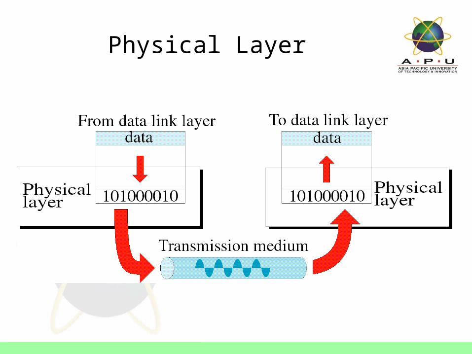
Physical Layer• The function of the physical layer is simply to allow a
stream of bits to be transmitted over a physical medium.
• It is concerned with the procedures of the interfaces and the physical line itself in order to facilitate the transmission over the link.
• It defines the physical characteristics of the network such as connections, voltage levels and timing.
• The data frames are translated into transmittable signals and put on the wire to travel across the network (or, in the case of wireless media, sent over the airwaves or by other means).
• The physical layer protocols turn all those 0s and 1s into electrical impulses or pulses of light
Physical Layer

Data Link Layer
• The data link layer is responsible for node-to-node delivery.
• Its primary concern is the ability to connect a sender to the receiver on one network - provides reliable transit of data across a physical network link
• This layer has been further divided into two sublayers:
• Media Access Control (MAC)• Logical Link Control (LLC)

Data Link Layer
• MAC Addressing• The MAC sublayer handles physical addressing
issues• In fact, the physical address, which on an Ethernet or
a Token Ring network is a hexadecimal number that is permanently burned into the chip on the network interface card (NIC), is called the MAC address
• The media access control method allocates access to the network by computers. Media access control occurs, appropriately enough, at the MAC sublayer
• Example: 0A-B1-C2-D3-E4-F5
Data Link Layer
• The LLC Layer and Logical Topology• At the LLC sublayer, the logical topology of
the network is defined• This sublayer is responsible also for providing
a link, or interface, between the MAC sublayer following it and the network layer above it

Data Link Layer

Data Link Layer

Network Layer
• The network layer is responsible for getting the data packets to their destinations
• It allows for connectivity between source and destination across multiple networks – by using logical address (network address/IP address). Routers can use this layer to determine how to forward packets. Because of this, much of the design and configuration work for internetworks happens at this layer.
• Nodes which are connected in one network usually do not use the functions of the network layer.
• This layer also handles prioritization of data types (the basis of Quality of Service [QoS]), which assures some level of guarantee for sufficient network resources for high-bandwidth applications such as live video

Network Layer

Transport Layer
• The transport layer ensures that the entire message is transmitted in order from source to destination.
• Where the network layer treats every packet individually, the transport layer looks at the entire message.
• The transport layer is also responsible for virtual connection creation.
• The transport layer accepts data from the session layer and segments the data for transport across the network.
• Generally, the transport layer is responsible for making sure that the data is delivered error-free and in the proper sequence.

Transport Layer
• End-to-end error control and flow control generally occur at the transport layer.
• Flow control manages data transmission between devices so that the transmitting device does not send more data than the receiving device can process.
• The transport layer keeps track of such things as validity of data packets, sequencing, and the handling of duplicate packets
• There are two protocol types used by the transport layer: connection-oriented and connectionless
• For connection oriented protocol, the transport layer on the receiving end can send an acknowledgment back to the sending computer to let the sender know that the packet arrived

Transport Layer

Session Layer
• The session layer establishes, manages, and terminates communication sessions.
• Communication sessions consist of service requests and service responses that occur between applications located in different network devices.
• This involves placing markers in the stream of data. If there is a communication failure, only the data from the most recent marker, or checkpoint, need to be resend.

Session Layer
• The session layer looks at the entire session and provides some form of dialog control.
• The session layer is responsible for ensuring the dialog mode(full, half, or simplex) and synchronization(checkpoints).• Full-duplex allows communication in both directions, and unlike
half-duplex, allows this to happen simultaneously. - e.g. telephone
• Half-duplex provides for communication in both directions, but only one direction at a time (not simultaneously) – e.g. walkie talkie
• Simplex communication flow in only one direction

Session Layer

Presentation Layer
• The application layer protocol receives the data from the user application and passes it down the stack to the presentation layer
• As its name suggests, this layer handles issues that have to do with the packaging or presentation of the data
• These issues include data compression, data encryption, protocol translation

Presentation Layer
• Data compression - This is the reduction of the size of the data to facilitate faster transmission over the network
• Data encryption - This is the conversion of data into an encoded form that cannot be read by unauthorized persons
• Protocol translation - This is the conversion of data from one protocol to another so that it can be transferred between dissimilar platforms or operating systems
• The presentation layer on the receiving computer is responsible for uncompressing, decrypting, and otherwise translating data into a format understandable by the application

Presentation Layer

Application Layer
• The first and most important thing to understand about the application layer is that it is not the user application that creates the message
• Rather, this layer provides for interaction between that application program and the network
• Protocols that function at the application layer perform functions such as file transfers, printing access, and messaging services
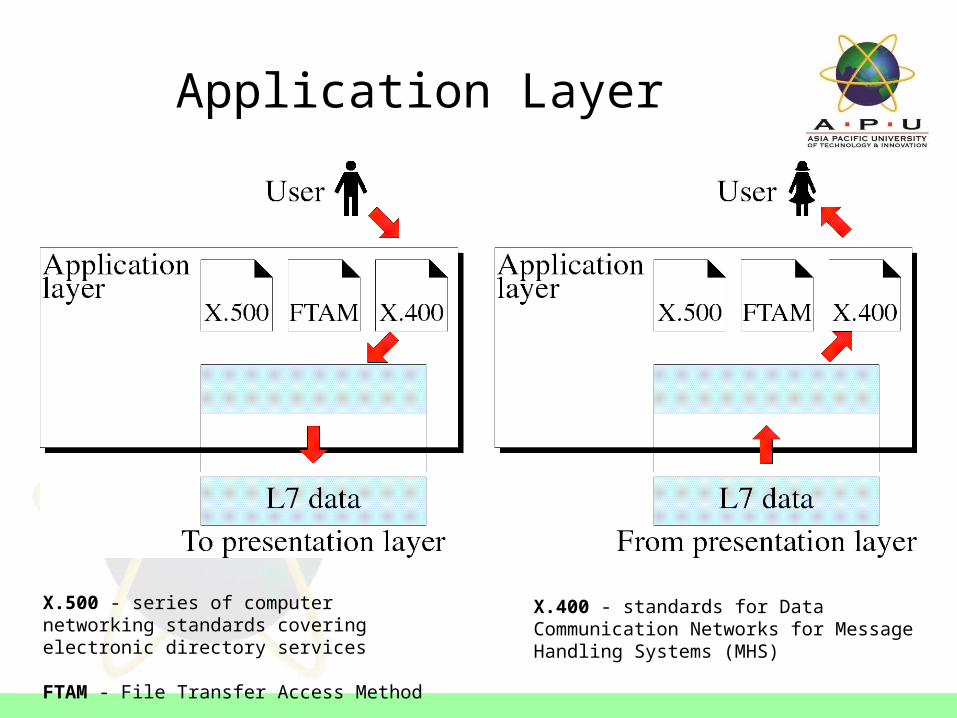
Application Layer
X.500 - series of computer networking standards covering electronic directory services
FTAM - File Transfer Access Method
X.400 - standards for Data Communication Networks for Message Handling Systems (MHS)

Transmission Control Protocol/ Internet Protocol
• TCP/IP• Where the OSI model describes how networks work,
the TCP/IP model describes how the Internet works.• The TCP/IP stack is the foundation of Internet
communications, and was developed before the OSI model came to place.
• It is quickly becoming the most common network/transport solution for networks of all sizes and configurations.
• The TCP/IP suite contains independent protocols which serve very specialized functions.

Ethernet
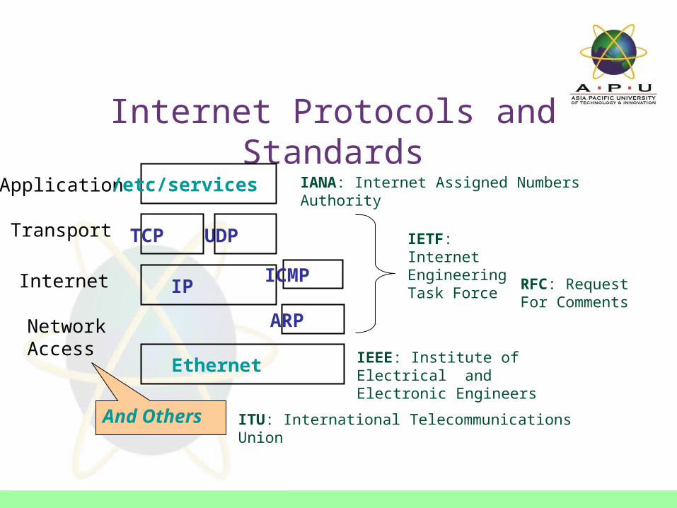
Internet Protocols and Standards
Application
Transport
Internet
NetworkAccess
ICMP
TCP UDP
IP
/etc/services
ARP
IETF: Internet Engineering Task Force
IEEE: Institute of Electrical and Electronic Engineers
IANA: Internet Assigned Numbers Authority
And Others
RFC: Request For Comments
ITU: International Telecommunications Union
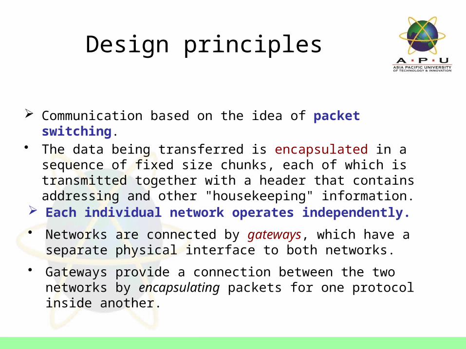
Design principles
Communication based on the idea of packet switching.• The data being transferred is encapsulated in a sequence of fixed
size chunks, each of which is transmitted together with a header that contains addressing and other "housekeeping" information.
Each individual network operates independently.
• Networks are connected by gateways, which have a separate physical interface to both networks.
• Gateways provide a connection between the two networks by encapsulating packets for one protocol inside another.

Design principles
Layering: standard conventions or protocols are needed so that the information is handled appropriately.
• Internet protocols are designed as a series of layers, where the physical communications medium is at the bottom and the top layer represents the applications that initiate and receive the messages that are transferred.
• Each layer builds on the services and capabilities provided by the lower layers.

Design principles
End-to-end protocols: Each layer of the protocol stack constitutes a communication channel between two endpoints that exchange messages.
• Between the sender of the data and its ultimate destination, the only thing that the network needs to examine is the destination address of the packets it must deliver.
• No data in the packets is processed in any way between the source and the destination.

Design principles
Least Mechanism: To send a packet, a source needs only know a "neighbour" that is connected to the network. Intermediate gateways and routers simply send each packet to a neighbour as the "next-hop" closer to the destination.
• Packets may arrive in any order, and delivery is on a best effort basis. If a packet does not make it to the final destination, the destination must contact the source with a request that it be retransmitted.
OSI
Presentation
Application
Physical
Data-Link
Network
Transport
Session
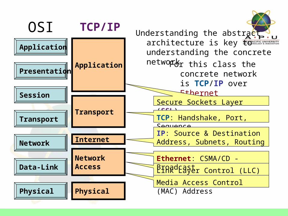
TCP/IP Understanding the abstract architecture
is key to understanding the concrete network
For this class the concrete network is TCP/IP over Ethernet
Application
Internet
Transport
Network Access
Physical
Secure Sockets Layer (SSL)
TCP: Handshake, Port, Sequence
IP: Source & Destination Address, Subnets, Routing
Link Layer Control (LLC)
Ethernet: CSMA/CD - Broadcast
Media Access Control (MAC) Address

HTTP Identical Message (end-to-end) HTTP
TCP Identical Segments (end-to-end) TCP
IP Identical Datagram
Intermediate Router (Layer 3)
or Switch (Layer 2)
Identical Datagram IP
Ethernet Proper Frame
Proper Frame Ethernet
Network Interface Wiring Network
InterfaceNetwork Interface Wiring Network
Interface
Let’s look into the details ...Host A Host B
Beyond a broadcast domain, communication is typically through a network of intermediate switching nodes.

TCP/IP over Ethernet
Application
Internet
Transport
Network Access
Physical
TCP: Handshake, Port, Sequence
IP: Source & Destination Address, Subnets, Routing
Link Layer Control (LLC)
Ethernet: CSMA/CD - Broadcast
Media Access Control (MAC) Address

Encapsulation
• A packet is a structured message.
• The control information of a given protocol must be treated strictly as data by the next "lower" protocol.
• As a packet moves down the protocol stack, it gets bigger as information relevant to the layer is added to the beginning and the end.
• Any given layer is allowed to work only with the data relevant to that layer, and nobody else's.
• As a packet moves up the stack it gets smaller, as the information from the current level is removed.

Packets and Encapsulation
Packets: Header and payload– Header tells where the packet came from
and where it’s going– Payload is the data
TCP layer it’s called a segment IP layer it’s called a packet Link layer it’s called a frame
CulturalSensitivity

Ethernet, IP, and TCP
TCP Segment Header
Data
IP Datagram Header
Complete TCP Segment Treated as Data
Frame Header
CRC Complete IP Datagram Treated as Data
Remember, this is really just a stream of bits0011110101010101110000101010101010001010110101001001010

Packet Size
Computer architecture calls eight bits a byte, Data communications calls eight bits an octet
• Maximum Transfer Unit (MTU) for Ethernet allows 12000 bits (1500 octets) of data. The actual size of the MTU depends on the network.
• TCP Segment sizes are negotiated by the sending and receiving systems, within the limit of their local network MTU.
• IP Datagrams can be broken into fragments to fit the recommended minimum Internet MTU of 576 octets. Each fragment maintains the same header information, followed by as much data as possible within the limit of the network MTU.

Preamble (64 bits)
Destination Address (48 bits)
Source Address (48 bits)
Packet type (16 bits)
Data (368-12,000 bits)
CRC (32 bits)
Ethernet Frame FormatKey Fields • Preamble: Alternating 1's and 0's to
help receiving nodes synchronise • Address: Unique identifier assigned
by the hardware manufacturer (MAC Address)
• Packet Type: identifies this as an Ethernet frame (allows mutiple protocols and versions)
• CRC: Error detection (Cyclic Redundancy Check)
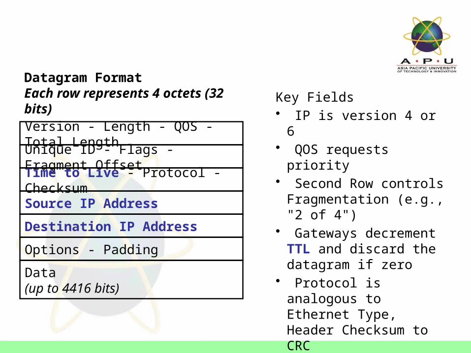
Datagram FormatEach row represents 4 octets (32 bits)
Version - Length - QOS - Total Length
Unique ID - Flags - Fragment Offset
Time to Live - Protocol - Checksum
Source IP Address
Destination IP Address
Options - Padding
Data(up to 4416 bits)
Key Fields • IP is version 4 or 6 • QOS requests priority • Second Row controls
Fragmentation (e.g., "2 of 4") • Gateways decrement TTL
and discard the datagram if zero
• Protocol is analogous to Ethernet Type, Header Checksum to CRC
• Options are included for network testing (not required)

TCP Segment FormatEach row represents 4 octets (32 bits)
Acknowledgement Number
Options - Padding
Source Port - Destination Port
Sequence Number
Offset - Code - Window
Checksum - Urgent
Data(up to 4224 bits)
Key Fields • Port number specifies service • Sequence is position in
sender's byte stream • Acknowledgement of position
in sender's byte stream • Some segments carry only
ACK, others carry data, and others a request to establish or close a connection (Code)
• Window and Options negotiate maximum segment size

Layer 2 and Layer 3 Switching
• Switching is the process of taking an incoming frame from one interface and delivering it out through another interface.
– Routers use Layer 3 switching to route a packet
– Switches use Layer 2 switching to forward frames.
• The difference between Layer 2 and Layer 3 switching is the type of information inside the frame that is used to determine the correct output interface.
– At Layer 2 frames are switched based on MAC address
– At Layer 3 packets are switched based on IP address

Routers connecting
remote sites
primary task is forwarding packets (datagrams)
encapsulation
Key concept: Encapsulation

Ethernet: MAC, LLC
• MAC address – The Data Link Layer uses a physical address for each
device called a Media Access Control address– MAC addresses are typically burned into the network
interface card (NIC). • LLC
– The Data Link Layer uses a Logical Link Control protocol to determine the type of Network Layer data is traveling inside the frame.
Network Access Link Layer Control (LLC)
Ethernet: CSMA/CD - Broadcast
Media Access Control (MAC) Address
Data-Link
Network

Ethernet: CSMA/CD
Carrier Sense – see if anyone is talkingMultiple Access – anyone can talkCollision Detection – did anyone else talk?
• CS: If nothing is arriving on the interface, send an outgoing frame• MA: Everyone on the segment uses the same wires to send and
receive
– an ethernet segment is a broadcast domain – an ethernet segment is analogous to an IP subnet
• CD: If an incoming frame clashes with an outgoing frame, wait a random period of time before sending again

TCP/IP over Ethernet
Application
Internet
Transport
Network Access
Physical
TCP: Handshake, Port, Sequence
IP: Source & Destination Address, Subnets, RoutingNetwork
Transport

TCP: Initial Connection Handshake
• TCP connections are full duplex streams.• Sequence numbers are established during the initial connection
using a “3-Way Handshake”.
• Other initial connection setup messages establish parameters of channel e.g., buffer sizes, error detection & recovery procedures.
TCP: Acknowledge or Retransmit
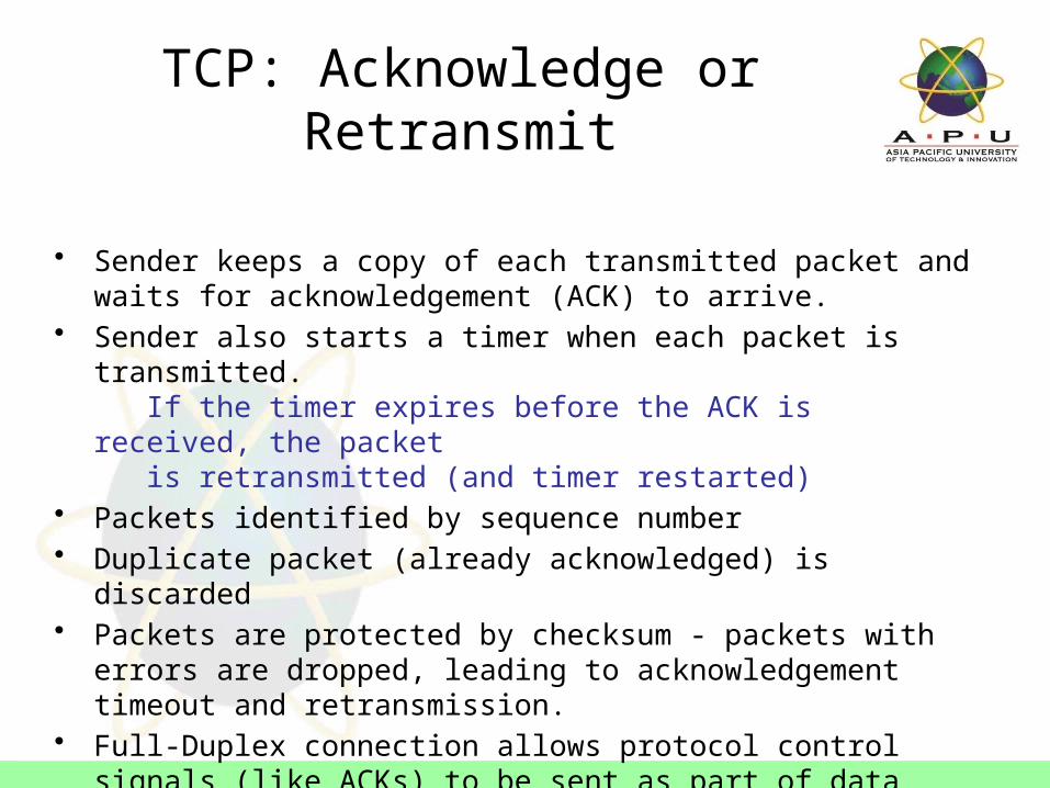
• Sender keeps a copy of each transmitted packet and waits for acknowledgement (ACK) to arrive.
• Sender also starts a timer when each packet is transmitted. If the timer expires before the ACK is received, the packet is retransmitted (and timer restarted)
• Packets identified by sequence number• Duplicate packet (already acknowledged) is discarded• Packets are protected by checksum - packets with errors are
dropped, leading to acknowledgement timeout and retransmission.• Full-Duplex connection allows protocol control signals (like ACKs) to
be sent as part of data travelling opposite direction

TCP: Flow Control
• Several packets may be transmitted at once, with one ACK for error-free arrival (sliding window)
• Available buffer at receiver determines maximum window size.• Reducing window size slows data flow
– Setting window size to zero halts data exchange!
Congestion avoidance:• Cut window size in half when timeout occurs• Lengthen time for ACK for retransmitted segments
– Allows gateways to clear datagrams already queued

UDP - User Datagram Protocol
• Connectionless service for application level procedures
– unreliable– delivery & duplication control not guaranteed
• Reduced overhead, least common denominator service• Used when one IP packet is sufficient for the whole message
– inward data collection– outward data dissemination– request-response– real time application

# This file contains port numbers for well-known services defined by IANA# Format:# <service name> <port number>/<protocol> [aliases...] [#<comment>]discard 9/tcp sink nulldiscard 9/udp sink nullqotd 17/tcp quote #Quote of the dayqotd 17/udp quote #Quote of the dayftp-data 20/tcp #FTP, dataftp 21/tcp #FTP. controltelnet 23/tcpsmtp 25/tcp mail #Simple Mail Transfer Protocoltime 37/tcp timservertime 37/udp timserverdomain 53/tcp #Domain Name Serverdomain 53/udp #Domain Name Serverbootps 67/udp dhcps #Bootstrap Protocol Serverbootpc 68/udp dhcpc #Bootstrap Protocol Clienttftp 69/udp #Trivial File Transferfinger 79/tcphttp 80/tcp www www-http #World Wide Web
Transport Protocol Addresses:TCP & UDP Port Numbers
/etc/services

• Ports– 16 bits– Ports under 1024 restricted to root

Used for gateway management:• congestion control (source quench)• route-change notification (redirect)• subnet addressing (address mask
request/reply)
Also for general network management:• reachability testing (echo request/reply)• performance measuring (timestamp)
ICMP - Internet Control Message Protocol

ARP - Address Resolution Protocol• Concerned with mapping layer 2 to layer 3 addresss, e.g.,
MAC address to IP address.
• The source host sends an ARP request by broadcast, asking “who has IP address A.B.C.D?”
If the destination host (which owns A.B.C.D) sees the ARP query, it responds and sends its MAC address.
If the destination host is not on the same local network, the router/gateway will respond and send its own MAC address.
• The source host registers the MAC address obtained and a data-link (layer 2) connection is established between the two hosts.
Ethernet
Internet Protocols and Standards
Application
Transport
Internet
NetworkAccess
ICMP
TCP UDP
IP
/etc/services
ARP
IETF: Internet Engineering Task Force
IEEE: Institute of Electrical and Electronic Engineers
IANA: Internet Assigned Numbers Authority
And Others
RFC: Request For Comments
ITU: International Telecommunications Union

Question and Answer Session
Q & A


