37
Standard Operating Procedures College Avenue Central Heating Plant Boiler Operations (Rev 1.1) April 23, 2013

Standard Operating Procedures
College Avenue Central Heating PlantBoiler Operations (Rev 1.1)
April 23, 2013
Chief Engineer: prepared by:Michael Snyder Asbjorn Nyhus

.Table of Contents
1. Plant Overview ----------------------------------------------------------- page 32. Systems ------------------------------------------------------------------- page 43. City Water ---------------------------------------------------------------- page 44. Water Softeners ---------------------------------------------------------- page 45. De-Aerator ---------------------------------------------------------------- page 46. Cascades ------------------------------------------------------------------- page 47. HTHW Pumps ------------------------------------------------------------- page 5 8. Condensate ---------------------------------------------------------------- page 59. Flash Tank ----------------------------------------------------------------- page 510. Natural Gas and Oil ------------------------------------------------------ page 511. Boilers ---------------------------------------------------------------------- page 612. Boiler #3 Startup Procedure --------------------------------------------- page 713. Boiler #4 Startup Procedure --------------------------------------------- page 814. Boiler #5 Startup Procedure --------------------------------------------- page 915. Isolating Cascade Tanks ------------------------------------------------- page 16. Operators Daily Responsibilities --------------------------------------- page 1017. Logbook procedures ------------------------------------------------------ page 1118. Water Testing -------------------------------------------------------------- page 1219. Lockout and Tag procedures -------------------------------------------- page 1420. Hot Work Permit Process ------------------------------------------------ page 1621. Troubleshooting ----------------------------------------------------------- page 22. Emergency Contact List ------------------------------------------------- page 23. Policies and Procedures -------------------------------------------------- page
2

Plant Overview
Introduction
The College Ave Central Heating Plant (CHP) Bldg # 3082 is located at 620 George Street. The system uses 3 high pressure steam boilers with cascade heaters to generate High Temperature Hot Water (HTHW) for distribution to various buildings on the campus. The plant is staffed 24 hours a day, 7 days a week/ 365 days a year. It has a capacity of 85 million btu/hr. of heating in the form of hot water, all supplied within one mile of piping distribution. High Temperature Hot Water heating is supplied to Campbell Hall, Hardenbergh Hall, Frelinghuysen Hall, and the SAC. Also, Clothier Hall, Hurtado Health Center, Brett Hall, Tinsley Hall, Mettler Hall, Stonier, the Gymnasium, Demarest Hall, Wessel’s Hall, and the Bishop House. Medium Temperature Hot Water is supplied to the Alexander Library and its addition, and the SCILS building. Low pressure steam is supplied to Brower Commons for cooking purposes. Low pressure steam is also used to heat Records Hall/Post Office, and The Learning Center.
3

Systems
City Water: CHP receives city water in two locations entering the plant. Located in the field house adjacent to the plant is the main feed into the plant. This line enters the plant and converges with the secondary line in the corner of the plant next to boiler #4. From there the city water branches to multiple locations with the primary lines feeding the water softening system with
bypasses to the DA, Cascades and Boilers.
Water Softeners: The water softeners are located behind boiler #3 against the wall. There are two softeners in tandem that primarily feed the De-Aerator with softened water. The water softeners work using a brine solution utilizing salt as the softening agent. Operators should check the salt levels in the container next to the softeners to ensure that it is full at all times. This check should be performed
by the day shift operator at least once every day.
De-Aerator: The De-Aerator (DA) is a large, insulated tank-car-shaped pressure vessel located above the water softeners. It uses low pressure steam from the LP header to produce pre-heated feedwater for the cascade tanks and the boilers. At elevated temperature even minute quantities of O2 cause severe corrosion in pipes, feedwater pumps and boilers.
A DA should scrub O2 levels down to 5-10 ppb (parts per billion). A vent pipe on the DA removes non-condensable gases. The addition of sulfites chemically ensures a “zero” level of dissolved gas in the feedwater.
Cascade Tanks:The two vertically mounted cascade tanks receive DA water when running the plant in normal configuration. They are fed by two cascade pumps located behind the water treatment room. The cascades can also be fed via bypassed softened or bypassed city water. The cascades heat water utilizing high pressure steam from the HP header. The cascades feed the boilers as well as providing High-Temperature-Hot-Water (HTHW) to the
Dormitories and other campus locations. Cascade water is pumped using a combination of 4 pumps in parallel to deliver it to the areas served. These pumps are located below the cascade tanks.
4
HTHW Pumps:The cascade tanks are fed into 4 HTHW pumps that are piped in parallel. This allows the system to be run from any single pump or combination of pumps. These HTHW pumps feed the library heat exchangers as well as the boilers. These pumps also feed other campus buildings.
Condensate:In a heat exchanger, the steam transfers its latent heat to a process fluid (HTHW). The steam is held in the heat exchanger by a steam trap until it condenses, at which point the trap passes the condensate into the condensate return system. The condensate is then returned to the DA for re-treatment and subsequent return to the system. The condensate tank is located behind boiler #4.
Flash Tank:The flash tank is used to collect and cool discharges of hot water from the boiler blow downs, boiler drains, cascade tanks and DA drain. It utilizes city water and an atmospheric vent to cool the hot discharge below 150 degrees Fahrenheit with a maximum 5 PSIG. The flash tank is located behind boiler #4.
5

Boilers:CHP utilizes 3 High Pressure steam boilers that are fired using either natural gas or #2 heating oil. Oil is used only during periods of extended cold and can be used up to 20 days per year.
Boiler #3Manufacturer: Superior HP 1740MAWP 250Operating Pressure 100Safety Valve Settings 145,150Serial # 2665-3885
Boiler #4Manufacturer: B&W HP 1176MAWP 300Safety Valve Settings 165,170Serial # 22791
Boiler #5 Manufacturer: SpringfieldHP 580MAWP 270Safety Valve Settings 145,150Serial # HSB575
6

Boiler Startup Procedures:
Boiler #3
Initial Conditions / Checks:1) Check boiler drum level. Ensure 60% level using BOTH digital display AND sight glass.2) Verify main steam stop valve # __ is open.3) Verify non-return valve # __ is open.4) Verify header valve # __ is open.5) Verify feedwater from Cascade valve #s __ and __ are open.6) Verify feedwater controller is set to AUTO.7) Verify at least one feed pump #s __ and/or __ are set to AUTO.8) Check DA Tank level.9) If the is no pressure on the boiler, ensure vent vale # __ is open. Close valve when steam begins to
issue from valve # __10) Ensure boiler controls are in MANUAL and set drum pressure setpoint to 15 psig when starting boiler
with no pressure.11) Do not place in AUTO until boiler has reached operating pressure (85 psig typical).12) Boiler Startup (Natural Gas):13) Ensure gas valve train valves are open (see gas train documentation page ?)
a) #b) #c) #d) #e) #
14) Select fuel type GAS from boiler control panel.15) Turn burner control to ON.16) When boiler is cold, slowly raise drum pressure setpoint until operating pressure is reached.17) Boiler Startup (Oil)18) Ensure oil gun is installed and in place (oil guns are located behind the boilers).19) Close atomizing steam line condensate drain valve # __.20) Open atomizing steam supply valve # __ at boiler.21) Open atomizing steam header valve # __.22) Ensure oil train valves are open
a) #b) #c) #d) #e) #
23) Start oil pump (see oil train documentation – page ?)
7

Boiler #4
Initial Conditions / Checks:1) Check boiler drum level. Ensure 60% level using BOTH digital display AND sight glass.2) Verify main steam stop valve # __ is open.3) Verify non-return valve # __ is open.4) Verify header valve # __ is open.5) Verify feedwater from Cascade valve #s __ and __ are open.6) Verify feedwater controller is set to AUTO.7) Verify at least one feed pump #s __ and/or __ are set to AUTO.8) Check DA Tank level.9) If the is no pressure on the boiler, ensure vent vale # __ is open. Close valve when steam begins to
issue from valve # __10) Ensure boiler controls are in MANUAL and set drum pressure setpoint to 15 psig when starting boiler
with no pressure.11) Do not place in AUTO until boiler has reached operating pressure (85 psig typical).12) Boiler Startup (Natural Gas):13) Ensure gas valve train valves are open (see gas train documentation page ?)
a) #b) #c) #d) #e) #
14) Select fuel type GAS from boiler control panel.15) Turn burner control to ON.16) When boiler is cold, slowly raise drum pressure setpoint until operating pressure is reached.17) Boiler Startup (Oil)18) Ensure oil gun is installed and in place (oil guns are located behind the boilers).19) Close atomizing steam line condensate drain valve # __.20) Open atomizing steam supply valve # __ at boiler.21) Open atomizing steam header valve # __.22) Ensure oil train valves are open
a) #b) #c) #d) #e) #
23) Start oil pump (see oil train documentation – page ?)
8

Boiler #5
Initial Conditions / Checks:1) Check boiler drum level. Ensure 60% level using BOTH digital display AND sight glass.2) Verify main steam stop valve # __ is open.3) Verify non-return valve # __ is open.4) Verify header valve # __ is open.5) Verify feedwater from Cascade valve #s __ and __ are open.6) Verify feedwater controller is set to AUTO.7) Verify at least one feed pump #s __ and/or __ are set to AUTO.8) Check DA Tank level.9) If the is no pressure on the boiler, ensure vent vale # __ is open. Close valve when steam begins to
issue from valve # __10) Ensure boiler controls are in MANUAL and set drum pressure setpoint to 15 psig when starting boiler
with no pressure.11) Do not place in AUTO until boiler has reached operating pressure (85 psig typical).12) Boiler Startup (Natural Gas):13) Ensure gas valve train valves are open (see gas train documentation page ?)
a) #b) #c) #d) #e) #
14) Select fuel type GAS from boiler control panel.15) Turn burner control to ON.16) When boiler is cold, slowly raise drum pressure setpoint until operating pressure is reached.17) Boiler Startup (Oil)18) Ensure oil gun is installed and in place (oil guns are located behind the boilers).19) Close atomizing steam line condensate drain valve # __.20) Open atomizing steam supply valve # __ at boiler.21) Open atomizing steam header valve # __.22) Ensure oil train valves are open
a) #b) #c) #d) #e) #
23) Start oil pump (see oil train documentation – page
9
Cascade Tank Procedures
Normal Operations:
The level of the cascade tanks is automatically controlled by the Eurotherm panel (fig 1) located across from MCC-2 near the HTHW pumps. The Eurotherm uses a pressure sensor to detect level in the tanks. It maintains 75% level in the tanks by modulating a valve located adjacent to the steps that lead to the DA (fig 2). The feedwater pumps (fig 3) are left in the AUTO position unless there is an emergency level condition. Under normal conditions the tank level may vary between 65% and 85% depending on load. As long as the levels remain in this range, no operator intervention should be necessary.
* When the valve is closed and the pumps are running the pressure relief valve (Fig 4) will open and re-circulate the water back to the DA. If the level in the Cascades exceeds 85% the system will turn OFF the pumps automatically.
10

Troubleshooting Cascade System:
If the Cascade Tanks are overfilling (above 85%):1. Check the modulating valve (Fig 2) indicator (Fig 5) to ensure
that it is closed. The figure to the right shows it closed 0 = closed, 90 = fully open.
2. It is normal for the valve to be partially open even if the tanks are above 75%.
3. The valve can be manually closed by turning the valve handle on top counter-clockwise.
4. The pumps can be left in auto.5. If the tanks continue to overfill you can turn off the pumps
(Fig 3).6. You can also shut the manual feed valve #629 (Fig 6)7. If you shut the manual valve #629 you MUST turn off the
pumps (Fig 3).
If the Cascade Tanks are below 60% the following steps can be taken.1. Check DA level to be sure it isn’t low as well.2. Ensure that the feed pumps are running and the pneumatic
valve is open. (Figs 3,2 & 5)3. If the valve is stuck closed you can bypass the valve by
opening valve # 630 & valve # 632 (Fig 7)4. If there is a shortage of water coming from the DA you can
open the city water bypass located above the water treatment room (Fig 8)
11

Operator’s Daily Responsibilities
When starting any shift, an operator shall:
1) Check ALL water levels. This includes the DA, Cascades, and all 3 boilers.2) Physically check all pump operations.3) Check for stack smoke.4) Receive any written and oral information from operator on duty.5) Sign in logbook (see page 11) when satisfied that the plant is in stable condition.
During all shifts the following actions should be performed:
1) Blow down and test low water cutoffs on all boilers.2) Blow down gauge glasses on all boilers.3) Check boiler and connected pipes for leaks.4) Check burner flame on all operating boilers.5) Every two hours at a minimum, rounds need to be made and readings recorded.6) Check and, if necessary, clean all drain screens in floors.7) Blow down Cascade gauge glass on the first of each month or as needed.
Specific additional duties for each shift:
8 hr Day Shift (0800-1600) Clean water tower screens. Perform routine water tests. (see page 12) Check level of salt in brine tank and add salt as needed.
8 hr Evening Shift (1600-0000) <none>
8 hr Night Shift (0000-0800) Take fuel readings of natural gas AND oil Take makeup water reading (behind softeners)
12 hr Day Shift (0000-1200) Clean water tower screens. Perform routine water tests. Check level of salt in brine tank and add salt as needed.
12 hr Night Shift (1200-0000) Take fuel readings of natural gas AND oil Take makeup water reading (behind softeners)
12

Guidelines for New Jersey LogsN.J.A.C. 5:11
1) The pages of the log must be sequentially numbered and no page shall be removed under any circumstances.
2) The names of the chief engineer, shift engineers and any other permanent boiler room staff should be recorded together with the time and period of duration of the shift.
3) At the start of each shift, the names of the shift and other staff commencing duty should be entered, together with the time and period of duration of shift.
4) The names of any personnel in training during the shift should be recorded.5) The entry of persons to the boiler room (other that the regular operating staff) should be recorded
together with the purpose of being there.6) Any special instructions from the Chief Engineer relative to the maintenance, reapir work or special
operational procedures may be entered and signed by the Chief Engineer.7) Compliance with such instructions, on completion, should be logged.8) Any of the following typical functions should be logged:
a) Blow down of the boilerb) Blow down of the water columnc) Testing of low level controlsd) Testing of safety valvese) Operation of soot blowersf) Water samplingg) Addition of chemicalsh) Testing of modulating or on/off controls
9) Any malfunction of any item of equipment or control, mechanical, electrical or electronic, should be logged with the time of occurrence, together with the remedial action taken.
10) Any mechanical or electrical repairs initiated and/or completed should be entered.11) Any work performed outside the power house and time spent.12) At the end of the shift, the shift engineer should record those items he wishes to bring to the attention
of the next scheduled shift engineer, and sign off the log book.
Use a black pen for entries in the logbook. You must print legibly. Use military time.The logbook can be used as a legal document. Accordingly, no pages are to be removed under ANY circumstances.
13
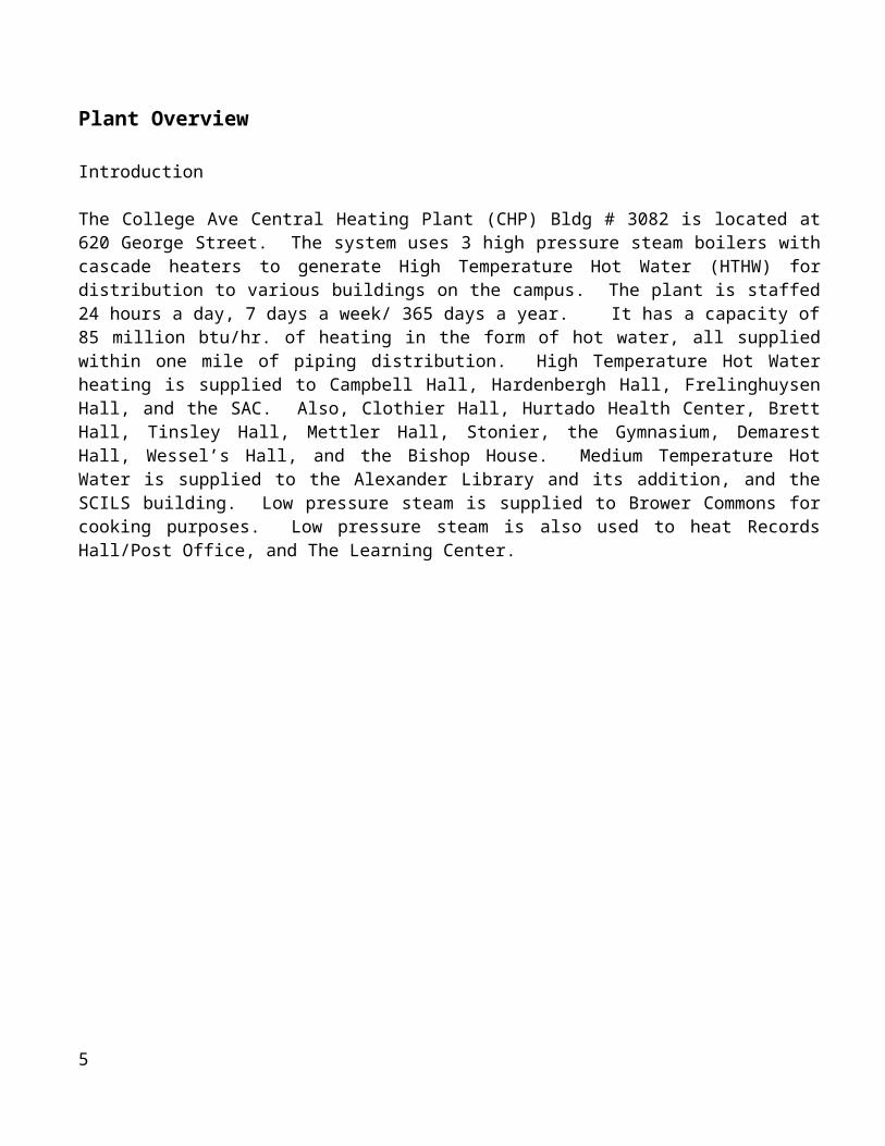
Water TestingWater samples are taken from the following locations:
1. Cascade: a. Below the cascade tanks is a sample cooler.b. Open the cooling water supply valve # __ and let run for 30 seconds
to 1 minute.c. Open valve # __ and then valve # __.d. Wait until water runs relatively clear and then fill sample bottle.
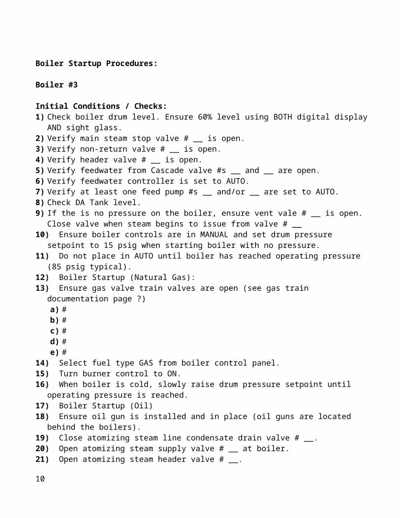
2. De-aerator:a. Adjacent to the DA pumps behind the water treatment room is the
sample cooler.b. Open the cooling water supply valve # __ and let run for 30 seconds
to 1 minute.c. Open valve # __, then valve # __ and finally valve # __.d. Wait until water runs relatively clear and then fill sample bottle.
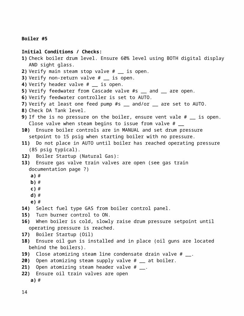
3. Condensate:a. Behind Boiler #4 is the condensate sample cooler.b. Open the cooling water supply valve # __ and let run for 30 seconds
to 1 minute.c. Open valve # __ and then valve # __.d. Wait until water runs relatively clear and then fill sample bottle.
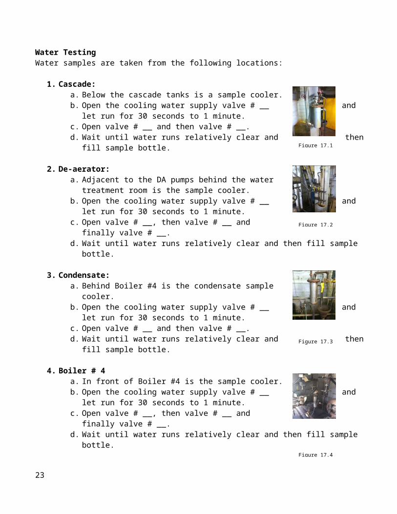
4. Boiler # 4a. In front of Boiler #4 is the sample cooler.b. Open the cooling water supply valve # __ and let run for 30 seconds
to 1 minute.c. Open valve # __, then valve # __ and finally valve # __.d. Wait until water runs relatively clear and then fill sample bottle.
5. Boilers # 3 and # 5a. Along the wall near the back of Boiler #3 is a sample cooler for both
boilers #3 and #5.b. Open the cooling water supply valve # __ and let run for 30 seconds
to 1 minute.c. Open valve # __ for boiler # 3 OR valve # __ for boiler #5.d. Then open valve # __ and wait until water runs relatively clear and
then fill sample bottle.6. Softeners
a. On top of the softeners behind Boiler #3 are the sample valves with hoses attached. Draw sample water from these hoses by opening the corresponding valve.
b. Softener #1 is on the left and Softener #2 is on the right.
14
Figure 17.1
Figure 17.2
Figure 17.3
Figure 17.4
Figure 17.5
Figure 17.6

Each day during the day shift, the operator on duty shall perform the following water tests. Results shall be recorded in the water treatment log and initialed by the operator. The log below shows what tests are performed for each water sample taken.
1. Hardness Test:a. Pour 25ml of the sample water
into vial.b. Add 5 Drops Buffer and swirl
liquid.c. Add 5 Drops Indicator and swirl
liquid.d. If color is BLUE, hardness is 0.e. If color is red or pink, add one drop of titrate at a
time until liquid turns blue.f. Each drop added equals 2 ppm hardness.g. Record the appropriate reading.
2. Alkalinity Test:a. Pour 25ml of the sample water into vial.b. Add 5 Drops Indicator and swirl liquid.c. If color does not change,
alkalinity is 0.d. If color is red or pink, add one
drop of titrate at a time until liquid turns clear.e. Titrates are either x50 or x10.f. Record the appropriate reading.
3. Conductivity and PH Tests:a. Add sample water to electronic tester.b. Press COND to read conductivity test.c. Press PH to read PH.
4. Dissolved Oxygen Test: (as directed by a. Take fresh ampule to DA sample cooler (pg12, #2).b. Open the cooling water supply valve # __ and let run for 30 seconds to 1 minute.c. Open valve # __, then valve # __ and finally valve # __.d. Let run for 10-15 seconds to purge.e. Insert ampule into test vial attached to valve # __.f. Break tip off ampule by pressing top of ampule against side of test
vial.g. Quickly remove ampule and invert several times to mix.h. Insert ampule (flat side down) into comparator and hold top to a light
source.i. Compare the colors and record the reading in the log.
15
SOFTENER 1 HARDNESS (<0.5)
CONDUCTIVITY
SOFTENER 2 HARDNESS (<0.5)
CONDUCTIVITY
CASCADE HARDNESS
CONDUCTIVITY
Dissolved O2 PPB
Ph (8.5-9.2)
DEAERATOR HARDNESS
CONDUCTIVITY
Dissolved O2 PPB
CONDENSATE CONDUCTIVITY (<50)
Ph (7.8-8.5)
BOILER 3 OH ALKALINITY (200-500)
CONDUCTIVITY (3000-4000)
BOILER 4 OH ALKALINITY (200-500)
CONDUCTIVITY (3000-4000)
BOILER 5 OH ALKALINITY (200-500)CONDUCTIVITY (3000-4000)
Figure 17.7
Figure 17.8
Figure 17.9

Lockout and Tag Procedures:
Purpose:
This procedure establishes the minimum requirements for the lockout of energy isolating devices whenever maintenance or servicing is done on machines or equipment. It shall be used to ensure that the machine or equipment is stopped, isolated from all potentially hazardous energy sources and locked out before employees perform any servicing or maintenance where the unexpected energization or start-up of the machine or equipment or release of stored energy could cause injury.
Compliance With This Program:
All employees are required to comply with the restrictions and limitations imposed upon them during the use of lockout. The authorized employees are required to perform the lockout in accordance with this procedure. All employees, upon observing a machine or piece of equipment which is locked out to perform servicing or maintenance shall not attempt to start, energize, or use that machine or equipment.
Sequence of Lockout:
5. Notify all affected employees that servicing or maintenance is required on a machine or equipment and that the machine or equipment must be shut down and locked out to perform the servicing or maintenance.
6. The authorized employee shall understand the hazards of the energy, and shall know the methods to control the energy.
7. If the machine or equipment is operating, shut it down by the normal stopping procedure (depress the stop button, open switch, close valve, etc.)
8. De-activate the energy isolating device(s) so that the machine or equipment is isolated from the energy source(s).
9. Lock out the energy isolating device(s) with assigned individual lock(s).
10. Stored or residual energy (such as that in capacitors, springs, elevated machine members, rotating flywheels, hydraulic systems, and air, gas, steam, or water pressure, etc.) must be dissipated or restrained by methods such as grounding, repositioning, blocking, bleeding down, etc.
11. Ensure that the equipment is disconnected from the energy source(s) by first checking that no personnel are exposed, then verify the isolation of the equipment by operating the push button or other normal operating control(s) or by testing to make certain the equipment will not operate. (Caution: Return operating control(s) to neutral or "off" position after verifying the isolation of the equipment.)
12. The machine or equipment is now locked out.
16

Restoring Equipment to Service:
1. When the servicing or maintenance is completed and the machine or equipment is ready to return to normal operating condition, the following steps shall be taken.
2. Check the machine or equipment and the immediate area around the machine to ensure that nonessential items have been removed and that the machine or equipment components are operationally intact.
3. Check the work area to ensure that all employees have been safely positioned or removed from the area.
4. Verify that the controls are in neutral.
5. Remove the lockout devices and reenergize the machine or equipment. (Note: The removal of some forms of blocking may require reenergization of the machine before safe removal.)
6. Notify affected employees that the servicing or maintenance is completed and the machine or equipment is ready for use.
[54 FR 36687, Sept. 1, 1989 as amended at 54 FR 42498, Oct. 17, 1989; 55 FR 38685, Sept. 20, 1990; 61 FR 5507, Feb. 13, 1996]
17

HOT WORK PERMIT PROGRAM
A. PURPOSE AND SCOPE:
1. PURPOSE: The purpose of the program is to establish written procedures to prevent fires resulting from any temporary operation involving open flames or producing heat and/or sparks as required by OSHA/PEOSHA 29 CFR 1910.252, 29 CFR 1926.352, the New Jersey Uniform Fire Code, and NFPA Standard 51B, 1962.
a. This includes, but is not limited to: brazing, cutting, grinding, soldering, thawing pipes, torch applied roofing and welding.
2. SCOPE: This program applies to work performed by Rutgers University employees and contractors performing work in existing buildings, new construction in existing buildings or new construction attached to existing buildings.
a. This program does not apply to new construction where there is NO ATTACHMENT to an existing building.
b. This program does not apply to areas that are specifically designed and equipped for such operations, i.e. maintenance shop areas and designated welding areas.
B. HOT WORK PERMIT PROCEDURES:
1. Hot work should not be performed if the work can be avoided or performed in a safer manner. When practical, objects to be welded, cut or heated must be moved to a designated safe location, i.e. maintenance shops.
2. If hot work must be performed, a Hot Work Permit must be obtained prior to any work from the following departments:
a. New Brunswick Campus – Department of Emergency Services. Contact University Police at 732-932-7211 and request that they notify the Emergency Services Sergeant on duty that a hot work permit is needed. The sergeant will report to the location of the hot work, inspect the area for code compliance, review safety procedures and issue the hot work permit.
b. Camden Campus – Physical Plant. Contact Physical Plant at 856-225-6000.
c. Newark campus – Campus Safety. Contact Campus Safety at 973-353-5478.
3. All precautions on the Hot Work Permit must be met prior to any work. The permit will be completed by an Emergency Services Sergeant on the New Brunswick Campuses, a designated representative from Physical Plant on the Camden Campus and a designated representative from Campus Safety on the Newark Campus. The permit will contain written safety procedures,
18

emergency telephone numbers, space for employee or contractor sign off, and a space for a fire watch sign off.
4. The Hot Work Permit is only good for the date(s) and time specified on the permit. A copy of the permit must remain at the hot work location.
5. All personnel (employees, contractors, building occupants) must be suitably protected against hazards generated by the work, i.e. heat, sparks, fumes, welding rays, etc. This may include, but is not limited to, the use of personal protective equipment, shields, screens, or local exhaust ventilation.
C. HOT WORK PERMIT – PROHIBITED CONDITIONS: A Hot Work Permit Will Not Be Issued If Any Of The Following Exists:
1. Sprinkler protection is impaired;
2. Appropriate fire fighting equipment is not readily available;
3. Combustible or Flammable materials are within 35 feet and cannot be moved or protected;
4. Floor and wall coverings cannot be covered;
5. Flammable vapors or gasses are present;
6. Cutting or welding pipes or other metals can conduct enough heat to ignite nearby combustible materials; or
7. Any condition that could result in undue hazards by performing the work.
D. RESPONSIBILITIES
1. DEPARTMENT RESPONSIBILITIES:
a. Recognize its responsibility for the safe usage of cutting and welding equipment in their area;
b. Establish areas for cutting and welding, i.e. maintenance shops;
c. Ensure hot work procedures are being implemented and followed in other areas;
d. Ensure that supervisors, cutters and welders are suitably trained in the operation of the equipment and the safe use of the process; and
e. Ensure that contractors follow University procedures.
19

2. SUPERVISOR RESPONSIBILITIES:
a. Ensure that all employees and contractors are utilizing hot work procedures;
b. Ensure that a hot work permit is retained prior to the start of work;
c. Ensure that all cutting and welding equipment is in satisfactory condition and in good repair; and
d. Ensure that employees are suitably trained in the operation of the equipment and the safe use of the process.
3. EMPLOYEE RESPONSIBILITIES:
a. Follow and use hot work procedures;
b. Obtain a hot work permit prior to any work;
c. Ensure that all cutting and welding equipment is in satisfactory condition and in good repair; and
d. Attend and actively participate in training sessions; and
e. Protect nearby personnel against heat, sparks, etc. when working in occupied buildings.
4. DEPARTMENT OF EMERGENCY SERVICES RESPONSIBILITIES:
a. Issue hot work permits on the New Brunswick Campuses;
b. Provide assistance and inspect areas prior to work; and
c. Provide assistance in training supervisors and employees.
5. CAMDEN PHYSICAL PLANT:
a. Issue hot work permits on the Camden Campus; and
b. Provide assistance and inspect areas prior to work.
6. NEWARK CAMPUS SAFTEY:
a. Issue hot work permits on the Camden Campus; and
b. Provide assistance and inspect areas prior to work.
20

7. REHS RESPONSIBILITIES:
a. Provide technical support;
b. Assist in providing training; and
c. Conduct periodic audits of the program.
21

Veeder-Root Oil Tank Monitoring System
Fernot Service: (973)575-8376
1. General Information1. 2 Oil Tanks2. Ullage: The dead space in tanks expressed in gallons3. 90% full – Federally mandated maximum level of tanks.4. System will set alarm condition at 90%5. 95% full will set – Hi Product Alarm6. Red Button – Alarm silence7. The only way to clear level alarms is to adjust the actual level of the tanks8. Fuel Alarm – Float switch in double walls and sumps indicate fuel or water leakage
22
2. Modes of Operation
There are three modes of operation
A. Set up ModeOnly used to change date/time.
B. Diagnostic ModeNot used by operators
C. Operator ModePassword – six ones (111111)
The operator mode has eight (8) functions Hitting the function button on the operating keypad cycles through each function Can print all parameters of each function by pressing “PRINT” Can cycle through each function on-screen by pressing “STEP” “BACK” is the opposite of “STEP”
The eight functions are:
1. In Tank Inventory: General tank statistic print out2. Shift Function: NOT USED3. In Tank Results Function: Displays test results from 4 hour Tank Test (see
step #6)4. CSLD: 24 hour Tank Test – runs automatically. Performs intense,
temperature compensated test of oil level/inventory to detect leaks (sensitivity to 0.2 gal/hr)
5. Liquid Status: Displays current status of sump and double-wall leak sensors Sensor Normal Sensor Out Fuel Alarm
6. Start “In Tank Leak Test” (See function #3): Starts a 4 hour version of CSLD with a sensitivity of 0.1 gal/hr. Use “CHANGE” button to cycle through the two choices All tanks – press “ENTER” Single Tank – press “ENTER”
7. Stop Tank Leak Test: Aborts test without getting a “test failure”8. Test Output Relays: Should be performed once a month. Select Relay #1 and
push red “ALARM TEST” button
23

24


