Stanley Access Technologies Installation and Operating Manual Double Diamond Sliding Door Installation Instructions Quick-Reference Guide 203973 Rev. Q, 4/15/09 Prohibition on Copying Any unauthorized reproduction, disclosure or distribution of copies by any person of any portion of this work may be a violation of copyright law of the United States of America and other countries, could result in the awarding of statutory damages of up to $250,000 (17 USC 504) for infringement, and may result in further civil and criminal penalties. All rights reserved.
Transcript
Stanley Access Technologies
Installation and Operating Manual
Double Diamond Sliding Door
Installation Instructions
Quick-Reference Guide
203973
Rev. Q, 4/15/09
Prohibition on Copying
Any unauthorized reproduction, disclosure or distribution of copies by any person of any portion of this work may be a violation of copyright law of the United States of America and other countries, could result in the awarding of statutory damages of up to $250,000 (17 USC 504) for infringement, and may result in further civil and criminal penalties. All rights reserved.
This manual provides installation instructions and a replacement parts listing for the Stanley Double Diamond automatic sliding door system. The Double Diamond is a heavy-duty telescoping sliding door package used in industrial and large retail-type operations. The unit is available in four-panel configurations in widths from 16 to 20 feet and heights from 10 to 12 feet. The synchronized doors can open wide to accommodate forklifts and other large equipment or open narrow to provide pedestrian passage.
1.2 Applicability
This manual is applicable to the Stanley Double Diamond automatic sliding door. Instructions for installing optional accessories such as key switches, door alarm contacts, push plates, and door position switches are provided in separate installation manuals. This manual does not cover components installed by other companies.
1.3 Features and Functions
1.3.1 The Double Diamond sliding door includes the following features and functions:
• Surface installation on the outside or inside of the building
• Heavy duty control and extra motor gearbox
• Friction rollers on the fast panel lead edges
• Acrylite scratch-resistant glazing material
• Wall-mounted keypad for entry
• Welded panels
• Eight-laminate hook lock and armored strike
• Bottom rail kick plates
• Energy-absorbing crash bars
• Rotary door operating switch
• SU-100 motion sensors (eight required—four on each side)
• Optex OA-203C infrared presence sensors (four required—two on each side)
• Two-button remote opening
• Falcon sensors (four required—two on each side)
• Doorway holding beams (two pairs required for slow panels—upper and lower)
2.2 Protective barrier (caution/warning tape) has been set up to prevent unauthorized access to work area.
2.3 The packing list has been reviewed, and all required parts are included.
2.4 The area has been cleared of all obstructions.
2.5 The steel beam has been installed to accommodate mounting of the header.
2.6 Attachment 1 has been reviewed for the following:
• Definitions of the terms used in this procedure
• A listing of the documents, special tools and equipment, materials, and consumables used in this procedure.
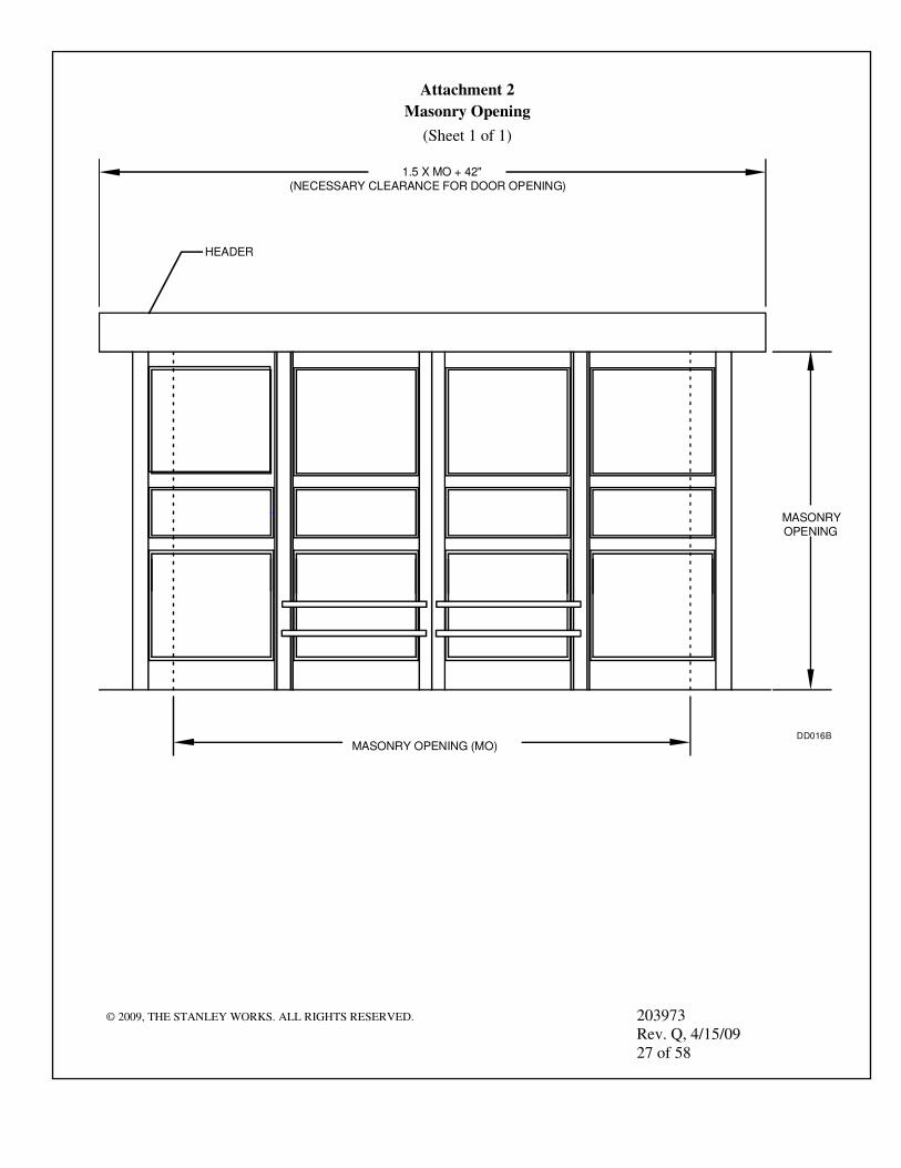
2.7 Attachment 2 has been reviewed to ensure that there is adequate clearance for the following:
• Opening the door fully.
• Installing the header.
3. PRECAUTIONS
3.1 The header and door panels are very heavy. Extreme caution must be used during installation. Two technicians and a power manlift are required to install this door package.
3.2 A licensed electrician is required to install conduit and bring high- and low-voltage supply wiring from the header to the rotary switch box. Electrician is also responsible for grounding the rotary switch box and both sides of the header using the ground strap provided.
3.3 When testing or operating doors, make certain there are no obstructions in the path of the panels.
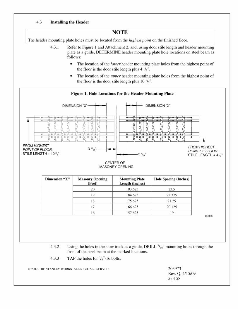
The header mounting plate holes must be located from the highest point on the finished floor.
4.3.1 Refer to Figure 1 and Attachment 2, and, using door stile length and header mounting plate as a guide, DETERMINE header mounting plate hole locations on steel beam as follows:
• The location of the lower header mounting plate holes from the highest point of
the floor is the door stile length plus 4 1/2″.
• The location of the upper header mounting plate holes from the highest point of
the floor is the door stile length plus 10 1/2″.
4.3.2 Using the holes in the slow track as a guide, DRILL 5/16″ mounting holes through the front of the steel beam at the marked locations.
4.3.3 TAP the holes for 3/8″-16 bolts.
Figure 1. Hole Locations for the Header Mounting Plate
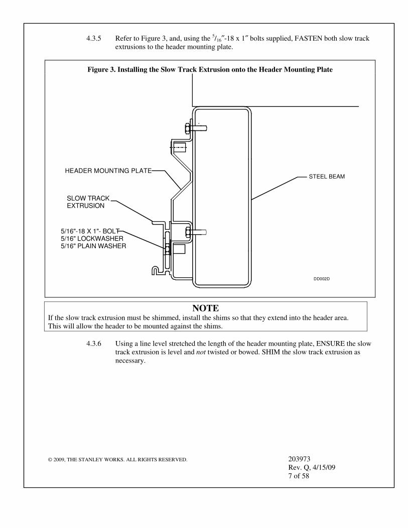
4.3.5 Refer to Figure 3, and, using the 5/16″-18 x 1″ bolts supplied, FASTEN both slow track extrusions to the header mounting plate.
NOTE If the slow track extrusion must be shimmed, install the shims so that they extend into the header area. This will allow the header to be mounted against the shims.
4.3.6 Using a line level stretched the length of the header mounting plate, ENSURE the slow track extrusion is level and not twisted or bowed. SHIM the slow track extrusion as necessary.
Figure 3. Installing the Slow Track Extrusion onto the Header Mounting Plate
STEEL BEAM
DD002D
HEADER MOUNTING PLATE
SLOW TRACK EXTRUSION
5/16"-18 X 1"- BOLT5/16" LOCKWASHER5/16" PLAIN WASHER
NOTE Typically, the header covers are installed after the headers have been mounted. When the installation site does not provide enough space to the left and right of the MO, the header covers must be installed before mounting the header.
4.3.7 MEASURE the space to the left and right of the header mounting location.
4.3.8 IF necessary, INSTALL header covers.
4.3.9 Refer to Figure 4, and POSITION the LH header above the slow track extrusion.
4.3.10 Using the 5/16″-18 x 1″ bolts supplied, FASTEN the LH header to the header mounting plate.
4.3.11 REPEAT steps 4.4.10 and 4.4.11 for the RH header.
4.3.12 Using a line level stretched the length of the header mounting plate, ENSURE the headers are level and not twisted or bowed. SHIM as necessary.
4.3.13 Using ¼″-20 x 1½″ bolts, FASTEN the header center bracket to the headers.
4.3.14 Using kit 516397, FASTEN the endcap dress plates to the headers.
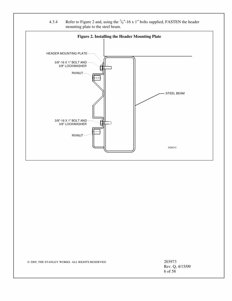
Figure 4. Installing the Header onto the Header Mounting Plate
STEEL BEAM
DD003D
SLOW TRACK EXTRUSION
HEADER MOUNTING PLATEHEADER
5/16"-18 X 1"- BOLT5/16" LOCKWASHER5/16" PLAIN WASHER
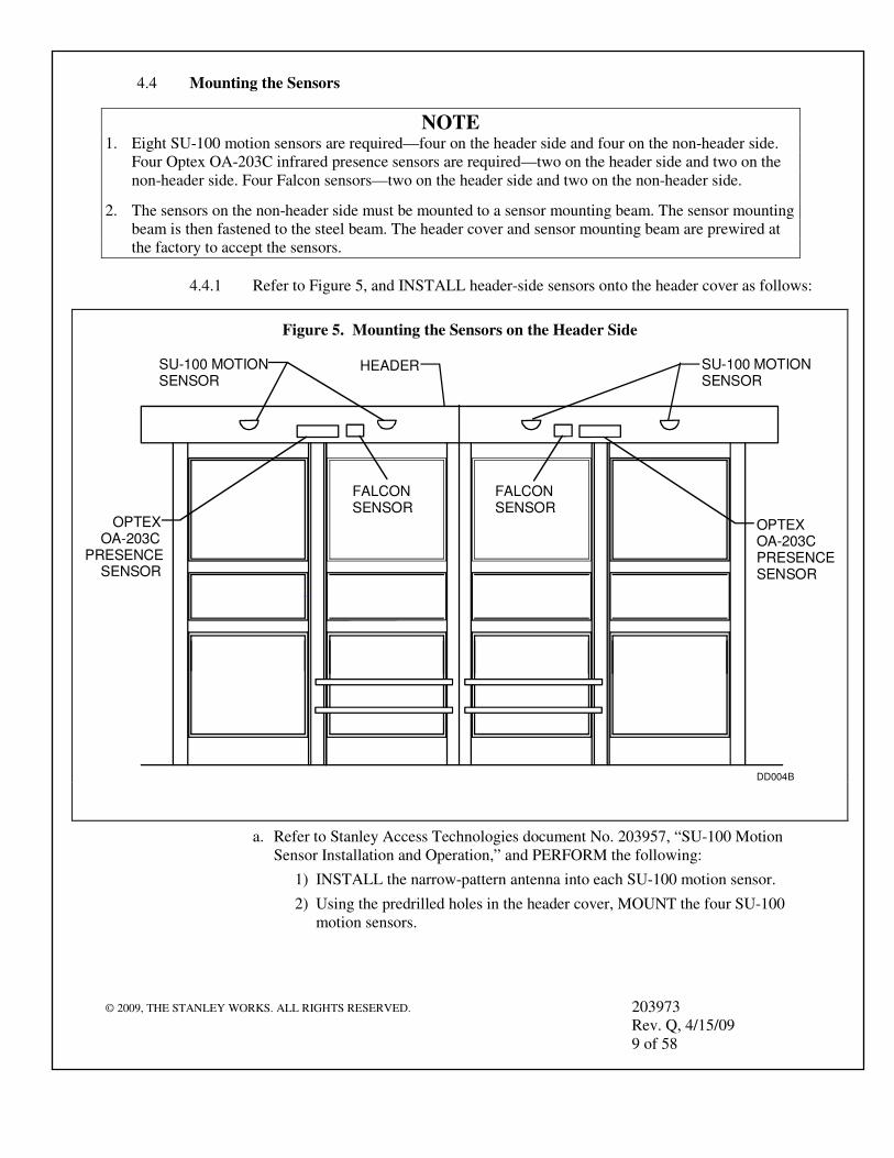
NOTE 1. Eight SU-100 motion sensors are required—four on the header side and four on the non-header side.
Four Optex OA-203C infrared presence sensors are required—two on the header side and two on the non-header side. Four Falcon sensors—two on the header side and two on the non-header side.
2. The sensors on the non-header side must be mounted to a sensor mounting beam. The sensor mounting beam is then fastened to the steel beam. The header cover and sensor mounting beam are prewired at the factory to accept the sensors.
4.4.1 Refer to Figure 5, and INSTALL header-side sensors onto the header cover as follows:
a. Refer to Stanley Access Technologies document No. 203957, “SU-100 Motion Sensor Installation and Operation,” and PERFORM the following:
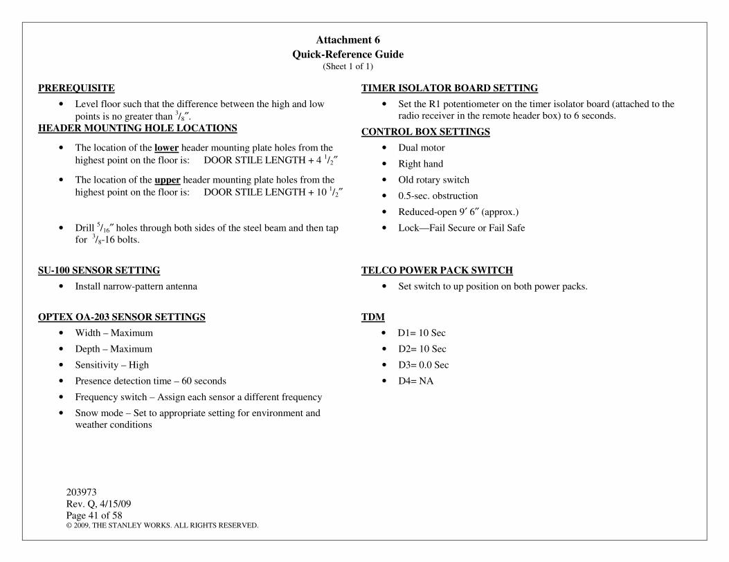
1) INSTALL the narrow-pattern antenna into each SU-100 motion sensor.
2) Using the predrilled holes in the header cover, MOUNT the four SU-100 motion sensors.
b. Refer to Optex OA-203C infrared presence sensor manufacturer’s installation and operating instructions, and PERFORM the following for each OA-203C sensor:
1) SET width to maximum.
2) SET depth (modes setting switches 7 and 8) to maximum.
3) SET presence detection time (modes setting switches 1 and 2) to 60 seconds.
4) SET the frequency selection (modes setting switches 3 and 4) such that each sensor is on a different frequency.
5) SET the snow mode (modes setting switches 5 and 6) to the setting that best matches the prevailing environment and weather conditions.
6) SET the sensitivity to high.
7) Using the predrilled holes in the header cover, MOUNT the two Optex OA-203C infrared presence sensors.
c. IF necessary, INSTALL header covers.
d. OPEN and CLOSE header covers and ENSURE they open and close freely without interference.
e. INSTALL the Falcon forklift sensors onto one header cover approximately 4½ ′ from the center of the door opening.
f. SET the Falcon forklift sensors for approximately 45°.
g. ATTACH sensor wires to the respective pull strings located at the edges of the header.
h. Using the pull strings, PULL sensor wires through the wire track to the center of the header.
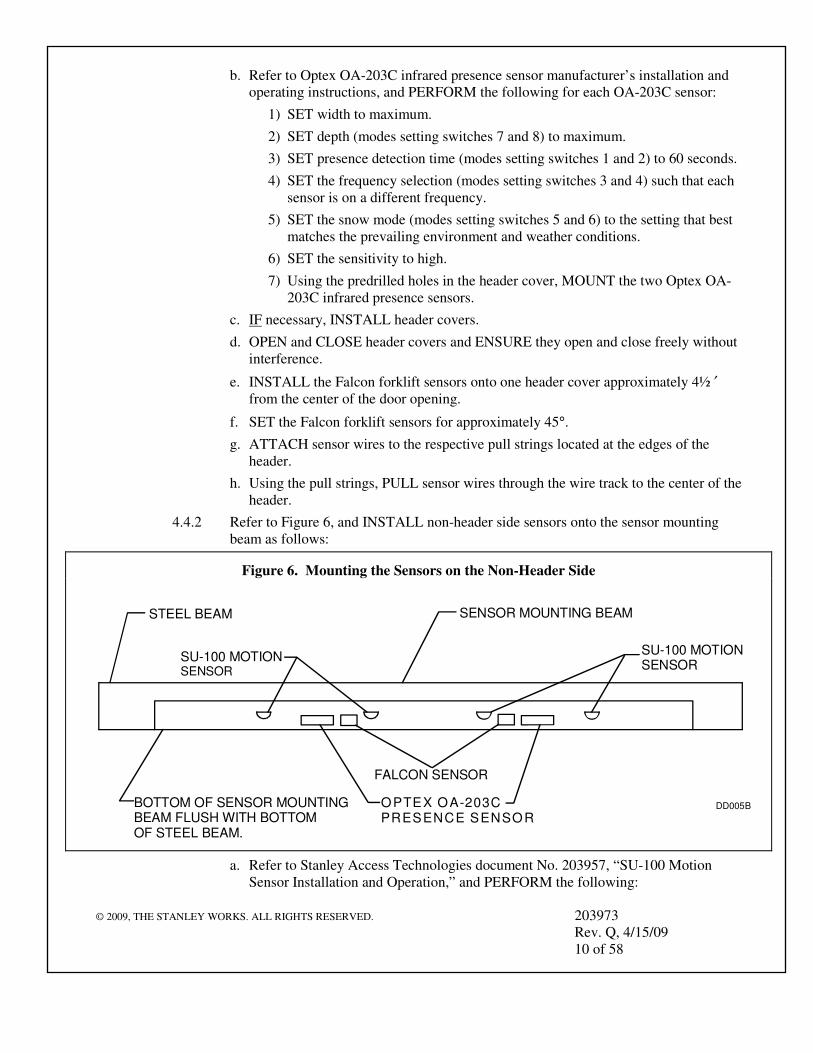
4.4.2 Refer to Figure 6, and INSTALL non-header side sensors onto the sensor mounting beam as follows:
a. Refer to Stanley Access Technologies document No. 203957, “SU-100 Motion Sensor Installation and Operation,” and PERFORM the following:
Figure 6. Mounting the Sensors on the Non-Header Side
DD005B
STEEL BEAM SENSOR MOUNTING BEAM
BOTTOM OF SENSOR MOUNTINGBEAM FLUSH WITH BOTTOM OF STEEL BEAM.
1) INSTALL the narrow-pattern antenna into each SU-100 motion sensor.
2) Using the predrilled holes in the sensor mounting beam, MOUNT the four SU-100 motion sensors.
b. Refer to Optex OA-203C infrared presence sensor manufacturer’s installation and operating instructions, and PERFORM the following for each OA-203C sensor:
1) SET width to maximum.
2) SET depth (modes setting switches 7 and 8) to maximum.
3) SET presence detection time (modes setting switches 1 and 2) to 60 seconds.
4) SET the frequency selection (modes setting switches 3 and 4) such that each sensor is on a different frequency.
5) SET the snow mode (modes setting switches 5 and 6) to the setting that best matches the prevailing environment and weather conditions.
6) SET the sensitivity to high.
7) Using the predrilled holes, MOUNT the two sensors to the sensor mounting beam.
c. DRILL holes in the steel beam and header to permit routing the wires from the sensor mounting beam to the header.
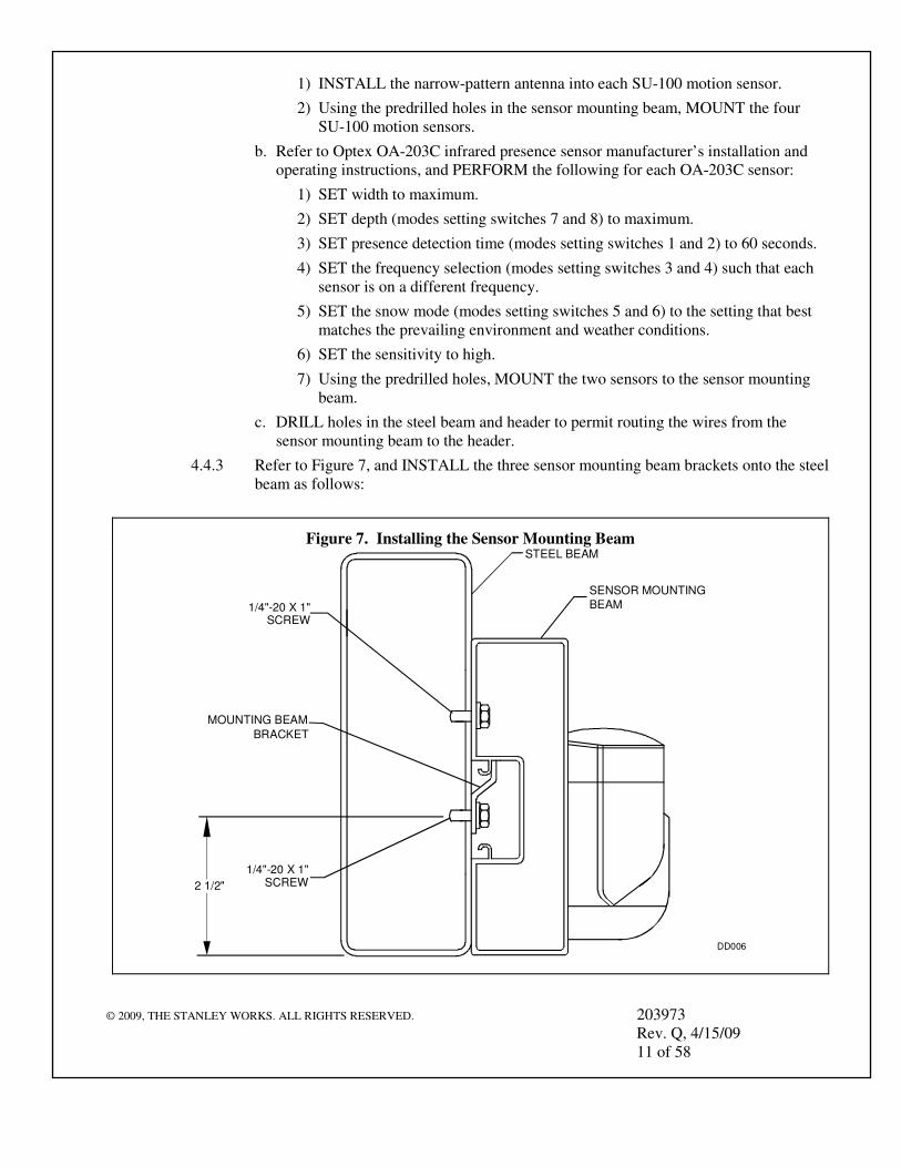
4.4.3 Refer to Figure 7, and INSTALL the three sensor mounting beam brackets onto the steel beam as follows:
a. Using the sensor mounting beam as a guide, DETERMINE the hole locations for the three evenly spaced sensor mounting beam brackets, and ENSURE the following:
• When the sensor mounting beam is hung, the bottom of the sensor mounting beam will be flush with the bottom of the steel beam.
b. Using a No. 7 drill bit, DRILL bracket mounting holes in steel beam.
c. TAP the bracket mounting holes for ¼-20 screws.
d. Using ¼-20 screws, FASTEN the three sensor mounting beam brackets to the steel beam.
e. HANG the sensor mounting beam on the mounting brackets.
f. Using a No. 7 drill bit and the sensor mounting beam holes as a guide, DRILL three mounting holes into the steel beam.
g. TAP the three mounting holes in the steel beam for ¼-20 screws.
h. Using ¼-20 screws, FASTEN the sensor mounting beam to the steel beam.
i. INSTALL hole plugs into three access holes.
j. INSTALL each Falcon forklift sensor approximately 41/2′ from the center of the door opening onto the center of the sensor mounting beam.
k. SET the Falcon forklift sensor for approximately 45°.
l. IF the sensor mounting beam is mounted on the exterior of the building, CAULK the area between the sensor mounting beam and the wall.
4.5 Installing the Rotary Switch Box
NOTE
The rotary switch box contains the rotary switch and power switch. The rotary switch box should be located on an interior wall at a location specified by the General Contractor or Building Superintendent.
4.5.1 MARK the location of the rotary switch box on an interior wall.
4.5.2 DRILL four 11/16″ mounting holes into wall.
4.5.3 Using the 3/8″ masonry anchors, screws, and washers provided, FASTEN the rotary switch box to the wall.
4.6 Installing the Slow Panels
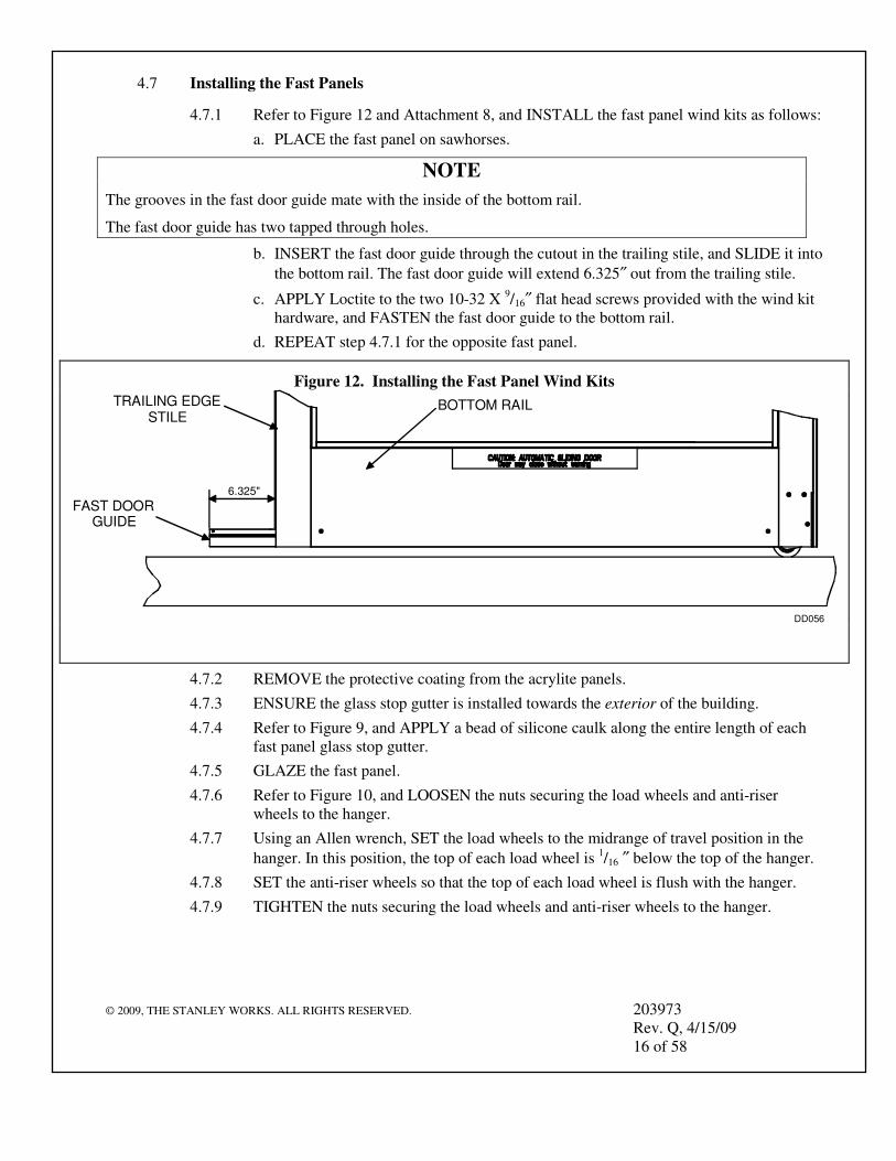
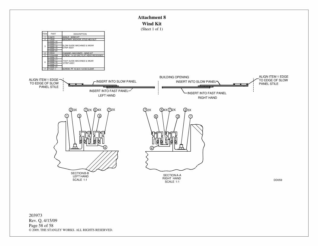
4.6.1 Refer to Figure 8 and Attachment 8, INSTALL slow panel wind kits as follows:
a. PLACE the slow panel on sawhorses.
NOTE
The grooves in the slow door guide mate with the inside of the bottom rail.
The slow door guide has eight through holes and two tapped holes.
b. INSERT the slow door guide through the cutout in the stile, and SLIDE it into the bottom rail. The slow door guide will not extend out of the slow panel.
c. APPLY Loctite to the two 10-32 X 1/2″ flat head screws provided with the wind kit hardware, and FASTEN the slow door guide to the bottom rail.
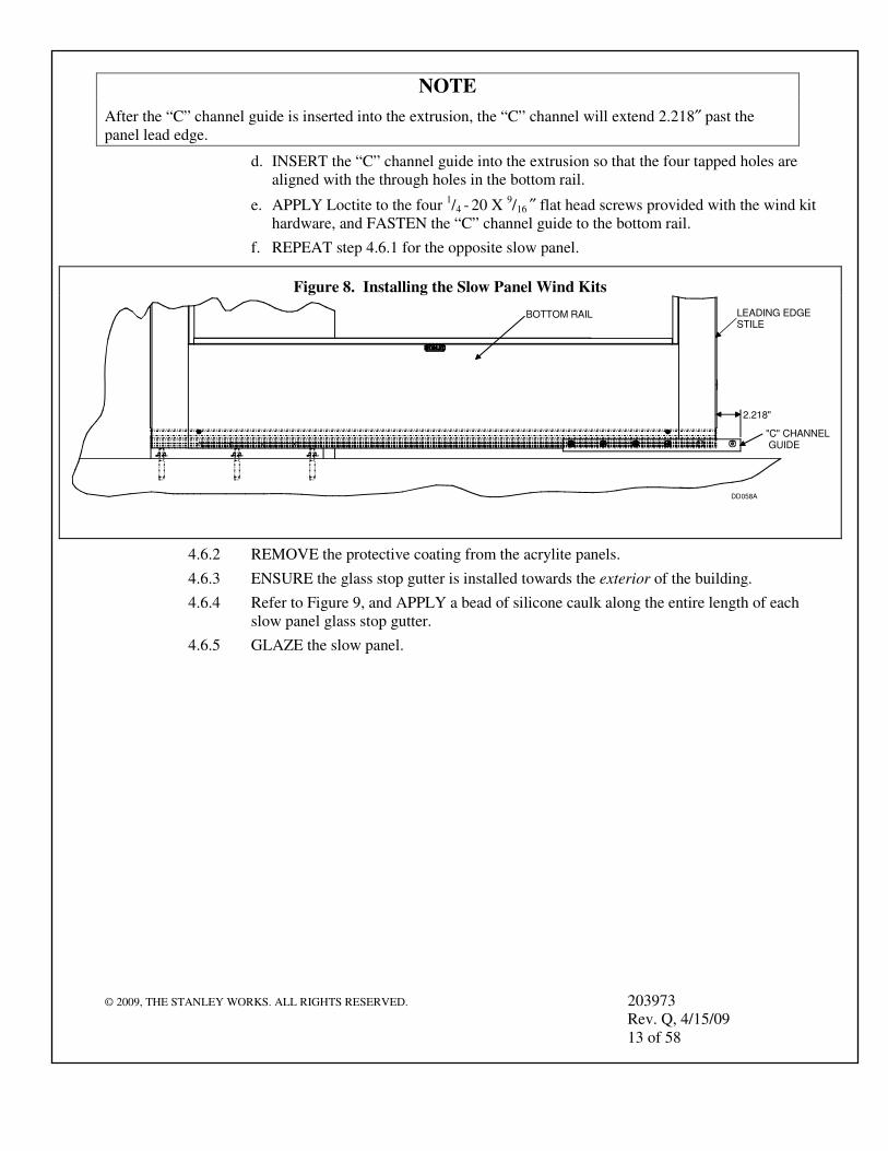
After the “C” channel guide is inserted into the extrusion, the “C” channel will extend 2.218″ past the panel lead edge.
d. INSERT the “C” channel guide into the extrusion so that the four tapped holes are aligned with the through holes in the bottom rail.
e. APPLY Loctite to the four 1/4 - 20 X 9/16 ″ flat head screws provided with the wind kit hardware, and FASTEN the “C” channel guide to the bottom rail.
f. REPEAT step 4.6.1 for the opposite slow panel.
4.6.2 REMOVE the protective coating from the acrylite panels.
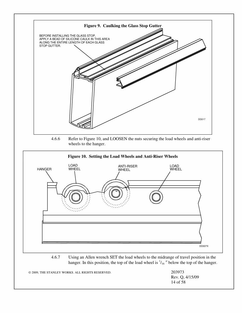
4.6.3 ENSURE the glass stop gutter is installed towards the exterior of the building.
4.6.4 Refer to Figure 9, and APPLY a bead of silicone caulk along the entire length of each slow panel glass stop gutter.
4.6.8 SET the anti-riser wheels so that the top of each wheel is flush with the top of the hanger.
4.6.9 TIGHTEN the nuts securing the load wheels and anti-riser wheels to the hanger.
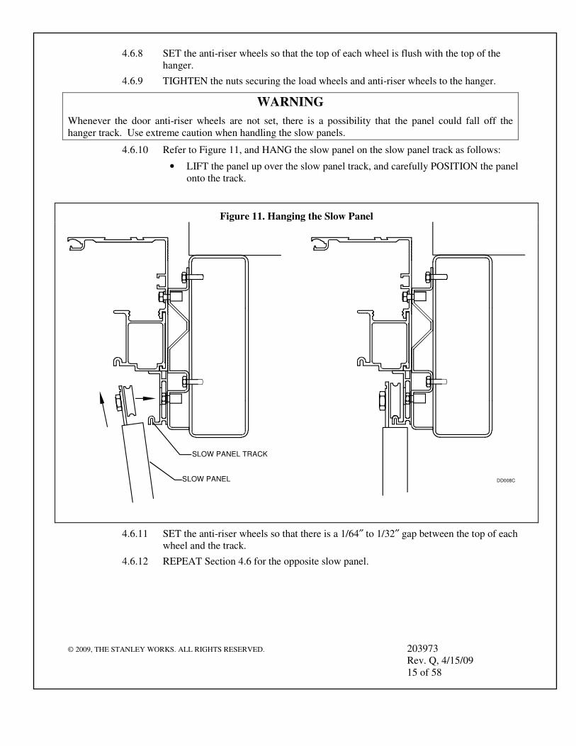
WARNING
Whenever the door anti-riser wheels are not set, there is a possibility that the panel could fall off the hanger track. Use extreme caution when handling the slow panels.
4.6.10 Refer to Figure 11, and HANG the slow panel on the slow panel track as follows:
• LIFT the panel up over the slow panel track, and carefully POSITION the panel onto the track.
4.6.11 SET the anti-riser wheels so that there is a 1/64″ to 1/32″ gap between the top of each wheel and the track.
4.6.12 REPEAT Section 4.6 for the opposite slow panel.
Whenever the door anti-riser wheels are not set, there is a possibility that the panel could fall off the hanger track. Use extreme caution when handling the fast panels.
4.7.10 Refer to Figure 13, and HANG the RH fast panel on the header track as follows:
• LIFT the panel up over the header track, and carefully POSITION the panel onto the track.
4.7.11 SET the anti-riser wheels so that there is a 1/64″ to 1/32″ gap between the top of each wheel and the track.
4.7.12 MOVE the fast panel into the open position, and ENSURE the leading edge of the fast panel is even with or slightly behind the edge of the masonry opening.
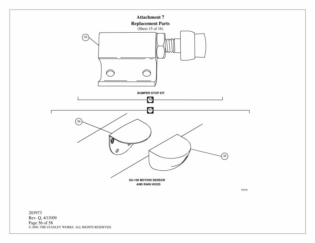
4.7.13 POSITION the fast panel bumper stop onto the header, and ENSURE the following:
• The bumper stop is on the correct track of the header.
• The bumper stop contacts the trailing edge of the rear fast panel hanger.
4.7.14 Using a 0.281″ drill bit and the holes in the bumper stop as a guide, DRILL bumper stop mounting holes into the header.
4.7.15 Using the ¼″-20 x 3/4″ screws provided, FASTEN the bumper stop to the header.
4.7.16 REPEAT Section 4.8 for the other fast door.
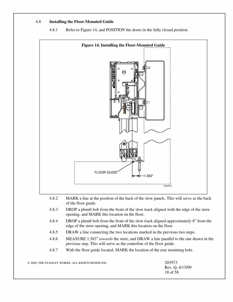
4.8.1 Refer to Figure 14, and POSITION the doors in the fully closed position.
4.8.2 MARK a line at the position of the back of the slow panels. This will serve as the back of the floor guide.
4.8.3 DROP a plumb bob from the front of the slow track aligned with the edge of the store opening, and MARK this location on the floor.
4.8.4 DROP a plumb bob from the front of the slow track aligned approximately 8″ from the edge of the store opening, and MARK this location on the floor.
4.8.5 DRAW a line connecting the two locations marked in the previous two steps.
4.8.6 MEASURE 1.583″ towards the store, and DRAW a line parallel to the one drawn in the previous step. This will serve as the centerline of the floor guide.
4.8.7 With the floor guide located, MARK the location of the rear mounting hole.
4.12.4 INSTALL the two 1¾″ slow panel top brushes (413344-2) onto the underside of the masonry opening as follows:
a. Using a No. 25 drill and the holes in the 1¾″ slow panel top brushes as a guide, DRILL slow panel top brush mounting holes into underside of masonry opening.
b. TAP slow panel top brush mounting holes for No. 10 screws.
c. Using No. 10 X 1/2″ screws, FASTEN the two 1¾″ slow panel top brushes to the underside of the masonry opening.
4.12.5 Using No. 8 self-tapping screws, FASTEN the two 11/2″ slow panel edge brushes (413344-5) to the outboard ends of the slow panels.
4.12.6 CUT two of the 3 ¾″ (413344-3) brushes provided to the width of the panels.
4.12.7 CLOSE the doors.
4.12.8 APPLY brushes to the exterior of the fast doors so that the brushes meet the ground.
4.12.9 Avoiding the area of the guide wheel, FASTEN the brushes to the fast panels using the self-drilling, self-tapping screws provided.
4.12.10 APPLY the brushes to the interior of the slow panels so that the brushes meet the ground when the doors are closed.
4.12.11 FASTEN the brushes to the slow panels using the self-drilling, self-tapping screws provided.
4.12.12 OPEN and CLOSE the doors, and VERIFY that the brushes do not prevent the doors from functioning properly
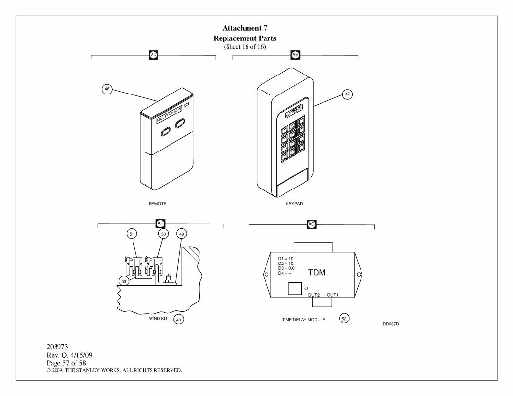
4.13 Installing the Keypad and Setting the Codes (U.S. Only)
4.13.1 MOUNT the keypad on the exterior wall.
4.13.2 Refer to manufacturer’s installation and operating instructions, and PERFORM the following:
a. SET the keypad receiver code to match the code for full-open receiver.
b. SET the input code per the customer’s request (typically the store number).
c. SET the remote code to match the receiver codes.
d. INSTALL the remote labels.
4.14 Programming the Handheld Remotes (U.S. Only)
NOTE
The two-button handheld remote is programmed so that button one activates the front door to full open, and button two activates the back door to full open.
4.14.1 Refer to manufacturer’s operating instructions, and SET the handheld remotes for the desired operation.
4.14.2 INSTALL applicable operating labels on remotes.
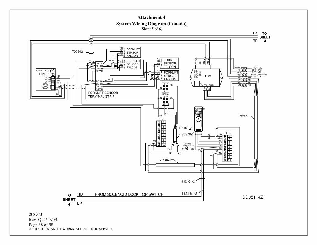
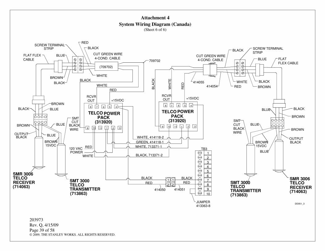
4.15 Wiring Part-Open and Full-Open Pushbuttons (Canada Only)
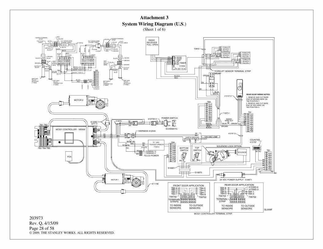
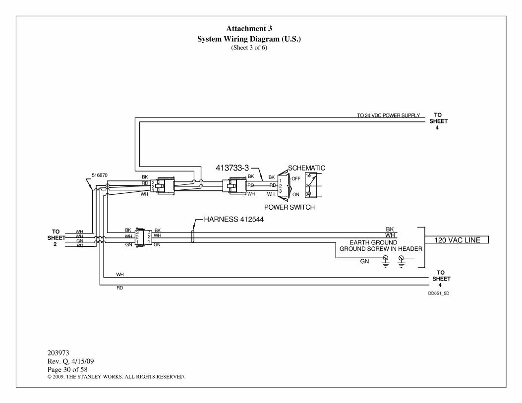
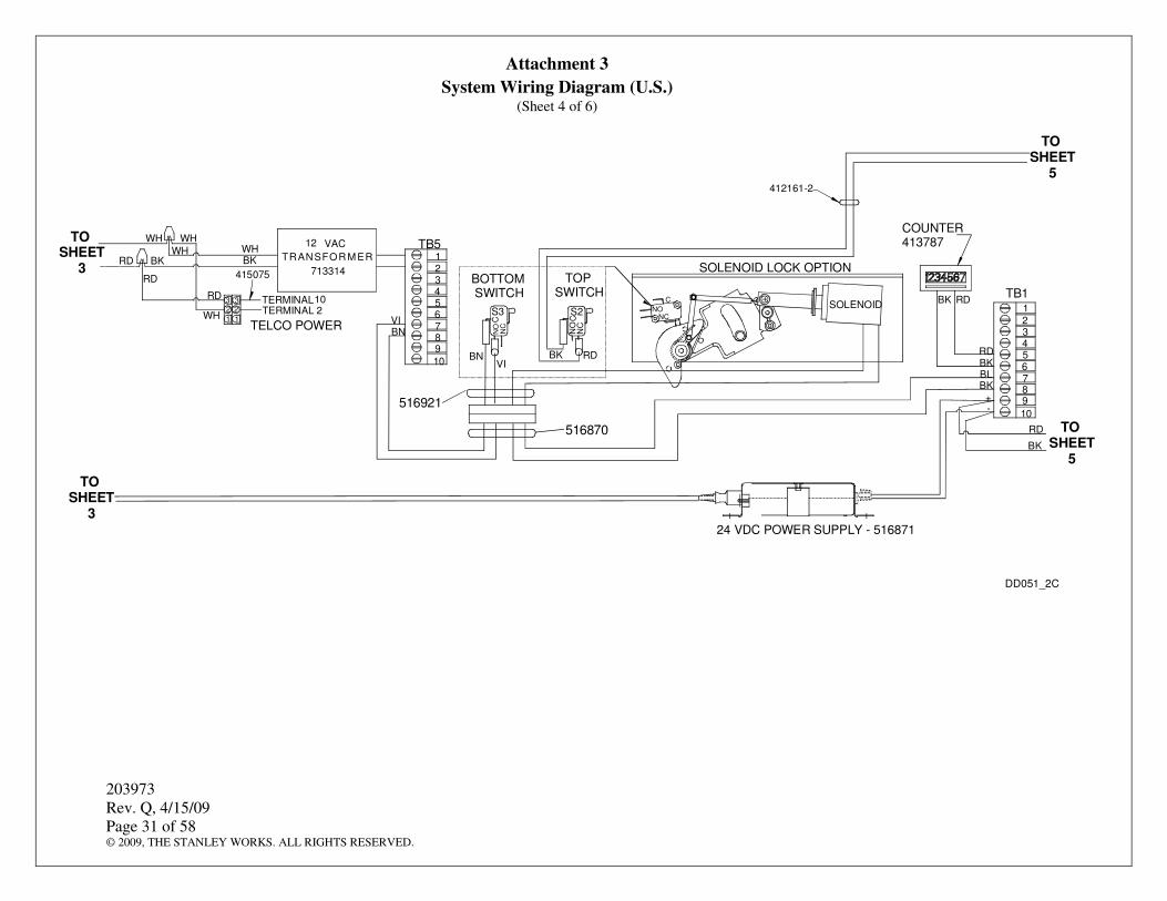
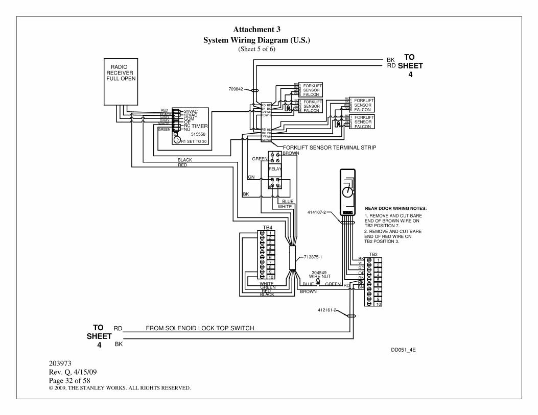
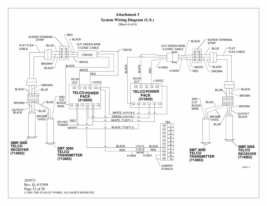
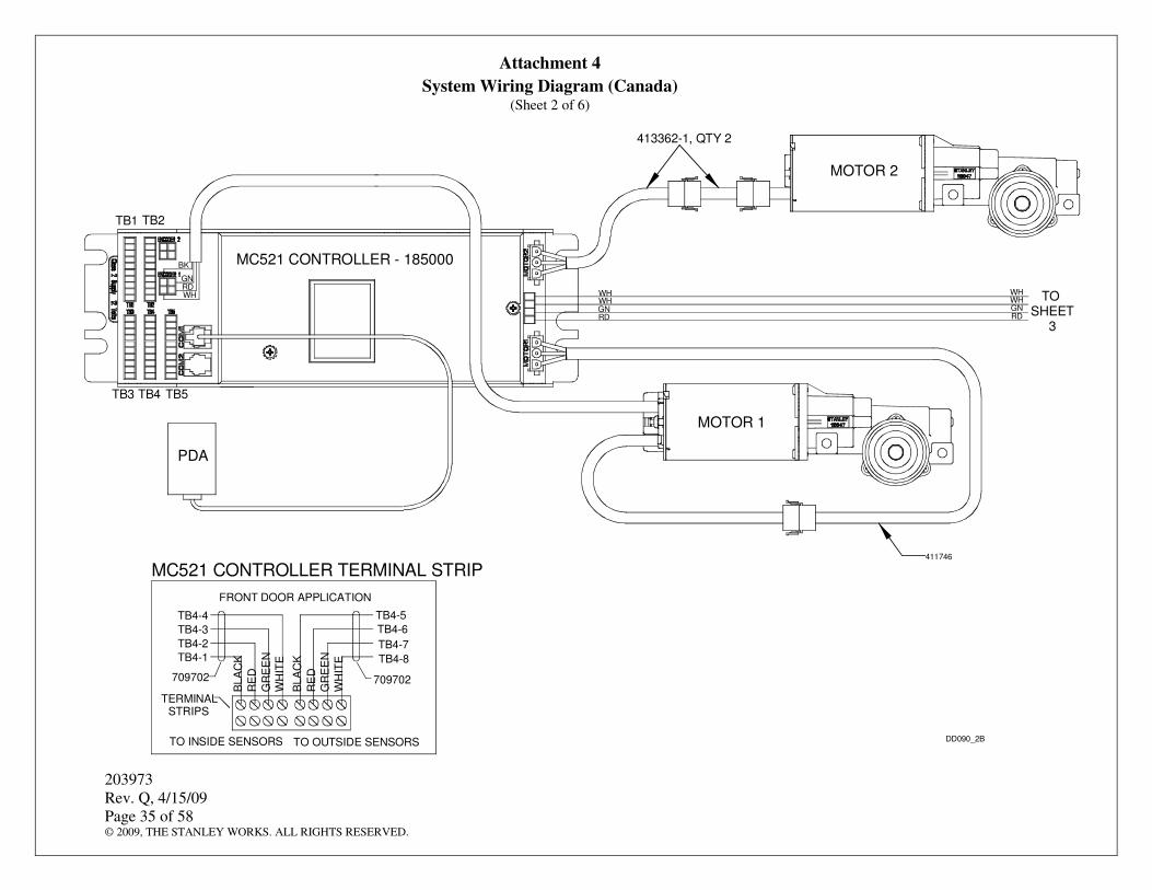
4.15.1 Refer to Attachment 3 or 4 as applicable and CONNECT part-open and full-open pushbuttons as necessary.
NOTE Operation of the front door with the rotary switch in the “AUTOMATIC” position is as follows: Activation from the Falcon forklift sensor causes the doors to open fully. Activation from the keypad causes the doors to open fully. Activation from the sensors causes the doors to open to reduced-open position. When the rotary switch is set to the “AUTOMATIC EXIT ONLY” position, the door is in one-way mode.
Operation of the back door with the rotary switch in the “AUTOMATIC” position is as follows: Activation from the Falcon forklift sensor causes the doors to open fully. Activation from the keypad causes the doors to open fully. The sensors are wired for safety only. There is no “AUTOMATIC EXIT ONLY” position on the back door rotary switch.
4.16.1 Refer to Stanley Access Technologies document No. 204003, “MC521 Controller Installation and Operation,” and PERFORM the following:
a. SET Door Type to “Slide Dual Motor.”
b. SET Handing to “Right.”
c. SET Function Switch to “Old Rotary.”
d. SET Door Obstruction Time to “0.5 sec.”
e. Refer to Stanley Access Technologies document No. 204003, “MC521 Controller Installation and Operation,” and TUNE-IN door.
4.16.2 Refer to Stanley Access Technologies document No. 203957, “SU-100 Motion Sensor Installation and Operation,” and TUNE-IN the SU-100 motion sensors.
4.16.3 Refer to manufacturer’s installation and operating instructions, and TUNE-IN the Optex OA-203C infrared presence sensors.
4.16.4 Refer to manufacturer’s user’s guide, and ADJUST the Falcon sensors as follows:
a. Using the infrared remote control, CONFIGURE the sensors for the following initial settings:
• Sensitivity: 9
• Hold Time: 9
• Relay configuration: 9
• Detection mode: 1
• Rejection mode: 5
b. ADJUST desired activation area per customer preference.
4.17.1 Using the 1/4″-20 x 5/8″ screws provided, FASTEN header cover to header.
4.17.2 Refer to Stanley Access Technologies document No. 203743, "Stanley Automatic Sliding Door Safety Decal Installation Guide," (supplied with door package) and PERFORM the following:
• INSTALL the safety decals.
• ENSURE the “CAUTION—STAND BACK” decal is installed on the walls over which the doors slide.
4.17.3 ENSURE acrylite panels are not cracked or broken.
4.17.4 ENSURE acrylite and metal surfaces are clean.
4.17.5 ENSURE door installation area is clean and free of debris.
4.17.6 ENSURE Stanley Service Sticker and all door decals/signage are properly displayed.
4.17.7 COMPLETE Final Inspection Checklist.
4.17.8 COMPLETE Work Order and REPORT your actions to the Building Superintendent.
4.17.9 PROVIDE “Daily Safety Checklist” and handheld remotes to building superintendent.
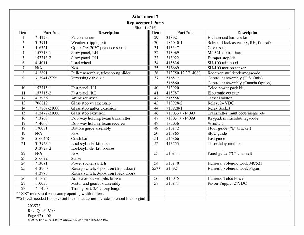
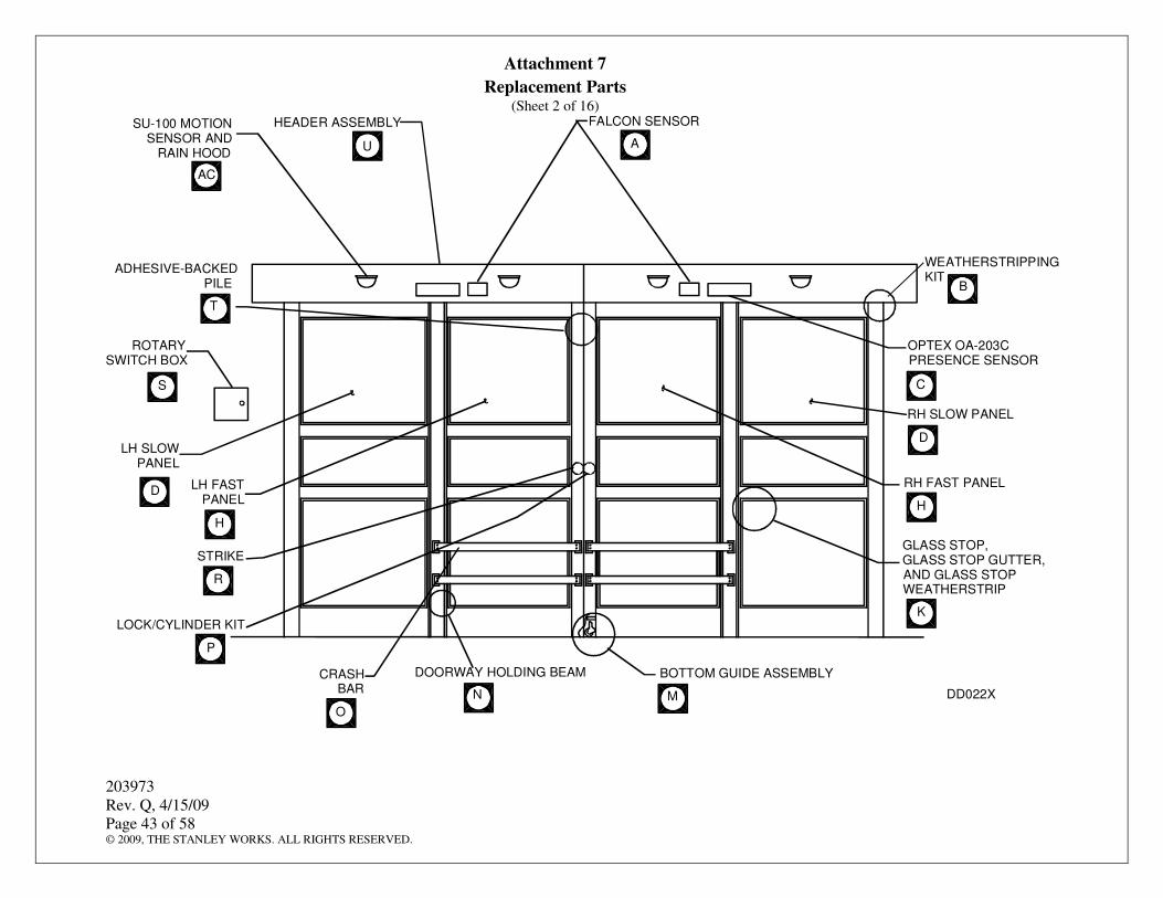
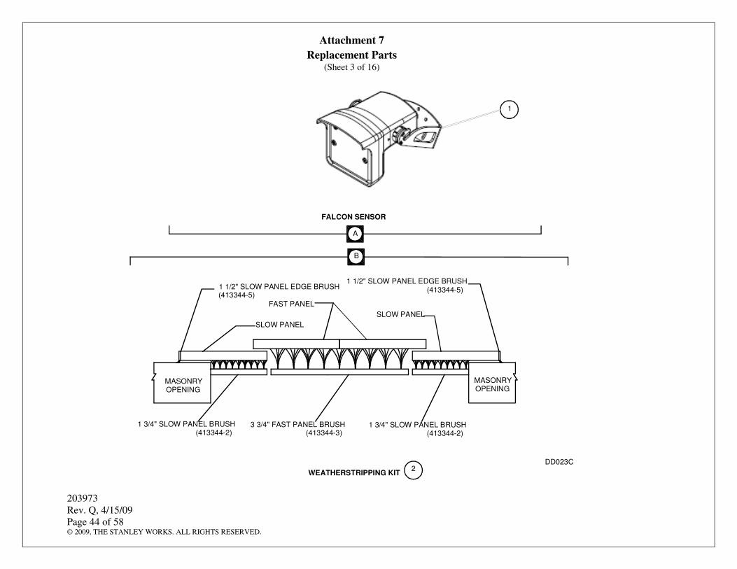
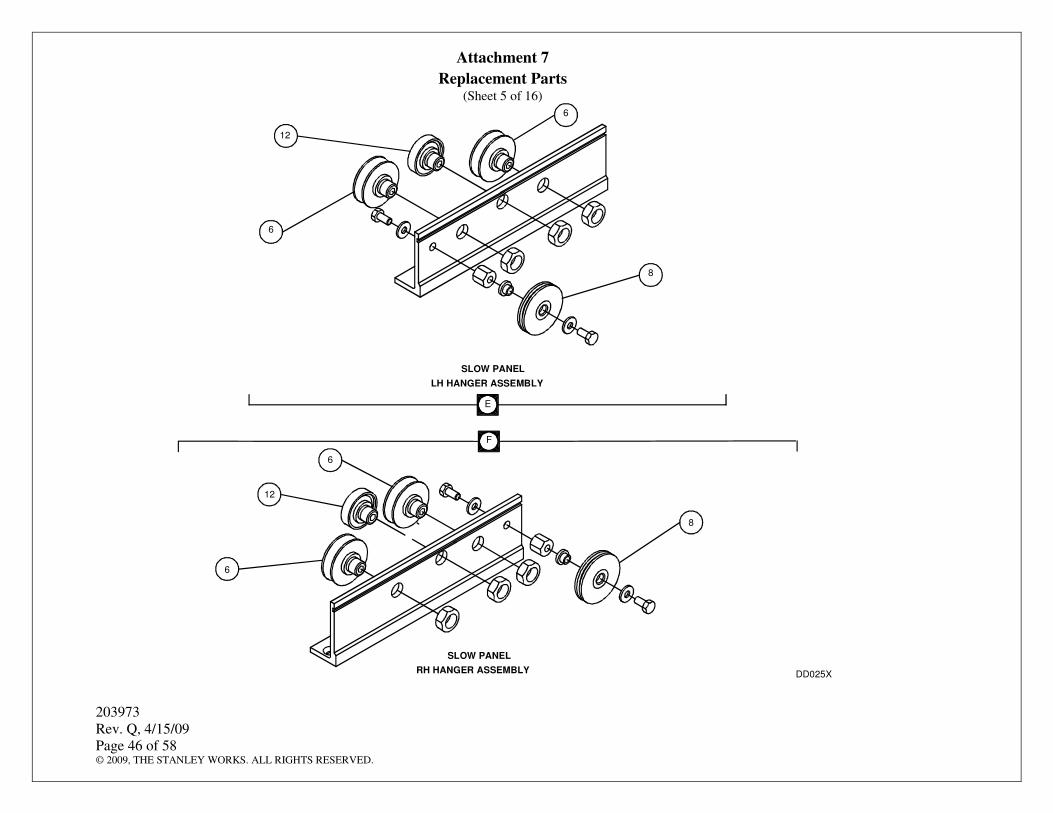
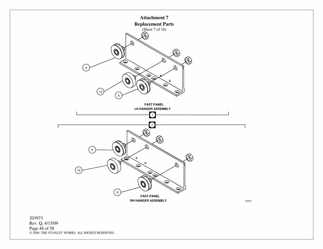
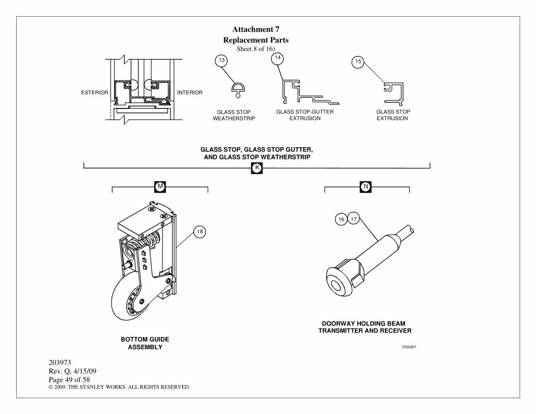
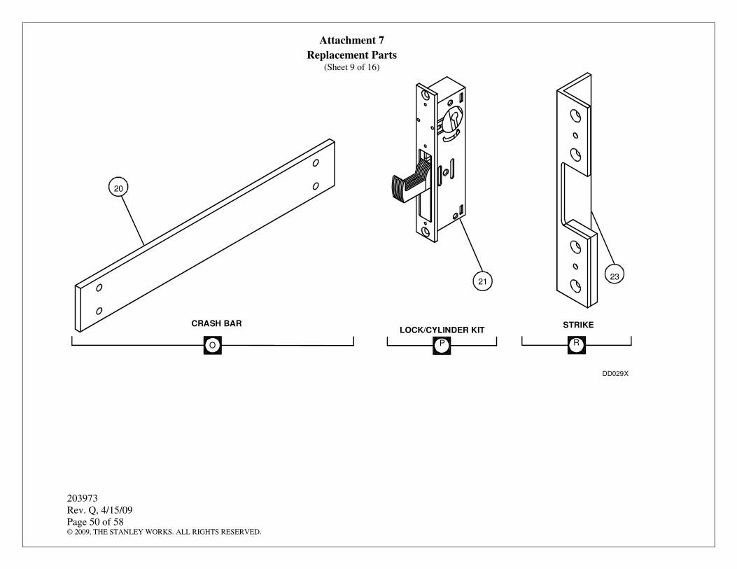
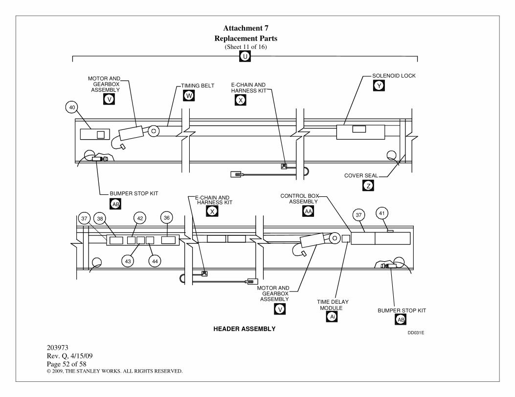
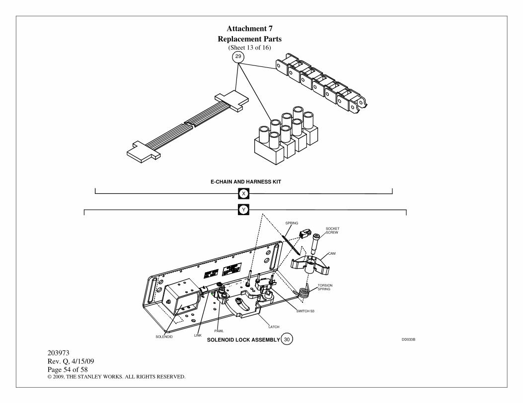
4.18 Replacement Parts
4.18.1 Refer to Attachment 7 for a listing of the Double Diamond replacement parts.