12
S.T.A.R.™ Type CR faulted circuit indicator installation instructions COOPER POWER SERIES Fault Indicators MN320009EN Effective March 2017 Supersedes August 2004 (S320-75-1)
S.T.A.R.™ Type CR faulted circuit indicator installation instructions
COOPER POWERSERIES
Fault IndicatorsMN320009EN
Effective March 2017Supersedes August 2004 (S320-75-1)
iInstallatIon InstructIons MN320009EN March 2017
DISCLAIMER OF WARRANTIES AND LIMITATION OF LIABILITY
The information, recommendations, descriptions and safety notations in this document are based on Eaton Corporation’s (“Eaton”) experience and judgment and may not cover all contingencies. If further information is required, an Eaton sales office should be consulted. Sale of the product shown in this literature is subject to the terms and conditions outlined in appropriate Eaton selling policies or other contractual agreement between Eaton and the purchaser.
THERE ARE NO UNDERSTANDINGS, AGREEMENTS, WARRANTIES, EXPRESSED OR IMPLIED, INCLUDING WARRANTIES OF FITNESS FOR A PARTICULAR PURPOSE OR MERCHANTABILITY, OTHER THAN THOSE SPECIFICALLY SET OUT IN ANY EXISTING CONTRACT BETWEEN THE PARTIES. ANY SUCH CONTRACT STATES THE ENTIRE OBLIGATION OF EATON. THE CONTENTS OF THIS DOCUMENT SHALL NOT BECOME PART OF OR MODIFY ANY CONTRACT BETWEEN THE PARTIES.
In no event will Eaton be responsible to the purchaser or user in contract, in tort (including negligence), strict liability or other-wise for any special, indirect, incidental or consequential damage or loss whatsoever, including but not limited to damage or loss of use of equipment, plant or power system, cost of capital, loss of power, additional expenses in the use of existing power facilities, or claims against the purchaser or user by its customers resulting from the use of the information, recommendations and descriptions contained herein. The information contained in this manual is subject to change without notice.
Contents
DISCLAIMER OF WARRANTIES AND LIMITATION OF LIABILITY . . . . . . . . . . . . . . . . . . . . . . . . . . . . . . . . . . . . I
SAFETY FOR LIFE . . . . . . . . . . . . . . . . . . . . . . . . . . . . . . . . . . . . . . . . . . . . . . . . . . . . . . . . . . . . . . . . . . . . . . . . . III
SAFETY INFORMATION . . . . . . . . . . . . . . . . . . . . . . . . . . . . . . . . . . . . . . . . . . . . . . . . . . . . . . . . . . . . . . . . . . . . IIISafety instructions . . . . . . . . . . . . . . . . . . . . . . . . . . . . . . . . . . . . . . . . . . . . . . . . . . . . . . . . . . . . . . . . . . . . . . . . . . . . . . .iii
PRODuCT INFORMATION . . . . . . . . . . . . . . . . . . . . . . . . . . . . . . . . . . . . . . . . . . . . . . . . . . . . . . . . . . . . . . . . . . . .1
INSTALLATION PROCEDuRES . . . . . . . . . . . . . . . . . . . . . . . . . . . . . . . . . . . . . . . . . . . . . . . . . . . . . . . . . . . . . . . .1Primary cable preparation . . . . . . . . . . . . . . . . . . . . . . . . . . . . . . . . . . . . . . . . . . . . . . . . . . . . . . . . . . . . . . . . . . . . . . . . .1
Installation of the FCI . . . . . . . . . . . . . . . . . . . . . . . . . . . . . . . . . . . . . . . . . . . . . . . . . . . . . . . . . . . . . . . . . . . . . . . . . . . .2
Removing the FCI . . . . . . . . . . . . . . . . . . . . . . . . . . . . . . . . . . . . . . . . . . . . . . . . . . . . . . . . . . . . . . . . . . . . . . . . . . . . . . .3
Installation instructions for remote FISHEYE™ display . . . . . . . . . . . . . . . . . . . . . . . . . . . . . . . . . . . . . . . . . . . . . . . . . . .4
Installation instructions for small remote display . . . . . . . . . . . . . . . . . . . . . . . . . . . . . . . . . . . . . . . . . . . . . . . . . . . . . . .5
ii InstallatIon InstructIons MN320009EN March 2017
The instructions in this manual are not intended as a substitute for proper training or adequate experience in the safe operation of the equipment described. Only competent technicians, who are familiar with this equipment should install, operate and service it.
A competent technician has these qualifications:
● Is thoroughly familiar with these instructions.
● Is trained in industry-accepted high- and low-voltage safe operating practices and procedures.
● Is trained and authorized to energize, de-energize, clear, and ground power distribution equipment.
● Is trained in the care and use of protective equipment such as flash clothing, safety glasses, face shield, hard hat, rubber gloves, hotstick, etc.
Following is important safety information. For safe installation and operation of this equipment, be sure to read and understand all cautions and warnings.
Safety instructionsFollowing are general caution and warning statements that apply to this equipment. Additional statements, related to specific tasks and procedures, are located throughout the manual.
Safety for life!
SAFETYFOR LIFE
!SAFETYFOR LIFE
Eaton’s Cooper Power series products meet or exceed all applicable industry standards relating to product safety. We actively promote safe practices in the use and maintenance of our products through our service literature, instructional training programs, and the continuous efforts of all Eaton employees involved in product design, manufacture, marketing and service.
We strongly urge that you always follow all locally approved safety procedures and safety instructions when working around high-voltage lines and equipment and support our “Safety For Life” mission.
Safety information
DANGERHazardous voltage . Contact with high voltage will cause death or severe personal injury . Follow all locally approved safety procedures when working around high- and low- voltage lines and equipment .
WARNINGBefore installing, operating, maintaining, or testing this equipment, carefully read and understand the contents of this manual . Improper operation, handling or maintenance can result in death, severe personal injury, and equipment damage .
WARNING This equipment is not intended to protect human life . Follow all locally approved procedures and safety practices when installing or operating this equipment . Failure to comply may result in death, severe personal injury and equipment damage .
WARNING Power distribution and transmission equipment must be properly selected for the intended application . It must be installed and serviced by competent personnel who have been trained and understand proper safety procedures . These instructions are written for such personnel and are not a substitute for adequate training and experience in safety procedures . Failure to properly select, install, or maintain power distribution and transmission equipment can result in death, severe personal injury, and equipment damage .
This manual may contain four types of hazard statements:
DANGER Indicates an imminently hazardous situation which, if not avoided, will result in death or serious injury .
WARNING Indicates a potentially hazardous situation which, if not avoided, could result In death or serious injury .
CAuTION Indicates a potentially hazardous situation which, if not avoided, may result in minor or moderate injury .
CAuTIONIndicates a potentially hazardous situation which, if not avoided, may result in equipment damage only .
Hazard Statement Definitions
iiiInstallatIon InstructIons MN320009EN March 2017
CAuTIONThe Eaton Cooper Power series S .T .A .R .™ Type CR Faulted Circuit Indicator is designed to be operated in accordance with normal safe operating procedures . These instructions are not intended to supersede or replace existing safety and operating procedures . Read all instructions before installing the faulted circuit indicator .
Faulted circuit indicators should be installed and serviced only by personnel familiar with good safety practice and the handling of high-voltage electrical equipment . Improper operation, handling, or maintenance can result in death, severe personal injury, and equipment damage .
Product information
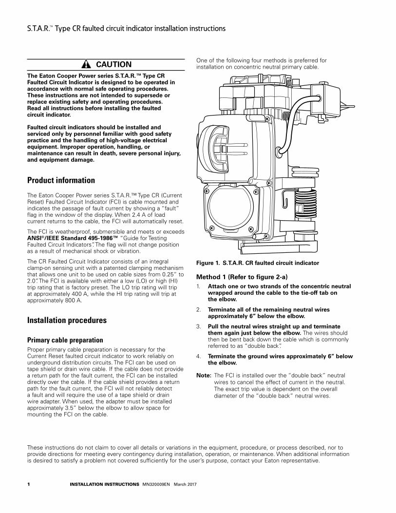
The Eaton Cooper Power series S.T.A.R.™ Type CR (Current Reset) Faulted Circuit Indicator (FCI) is cable mounted and indicates the passage of fault current by showing a “fault” flag in the window of the display. When 2.4 A of load current returns to the cable, the FCI will automatically reset.
The FCI is weatherproof, submersible and meets or exceeds ANSI®/IEEE Standard 495-1986™ “Guide for Testing Faulted Circuit Indicators”. The flag will not change position as a result of mechanical shock or vibration.
The CR Faulted Circuit Indicator consists of an integral clamp-on sensing unit with a patented clamping mechanism that allows one unit to be used on cable sizes from 0.25” to 2.0”. The FCI is available with either a low (LO) or high (HI) trip rating that is factory preset. The LO trip rating will trip at approximately 400 A, while the HI trip rating will trip at approximately 800 A.
Installation procedures
Primary cable preparationProper primary cable preparation is necessary for the Current Reset faulted circuit indicator to work reliably on underground distribution circuits. The FCI can be used on tape shield or drain wire cable. If the cable does not provide a return path for the fault current, the FCI can be installed directly over the cable. If the cable shield provides a return path for the fault current, the FCI will not reliably detect a fault and will require the use of a tape shield or drain wire adapter. When used, the adapter must be installed approximately 3.5” below the elbow to allow space for mounting the FCI on the cable.
One of the following four methods is preferred for installation on concentric neutral primary cable.
Figure 1 . S .T .A .R . CR faulted circuit indicator
Method 1 (Refer to figure 2-a)1. Attach one or two strands of the concentric neutral
wrapped around the cable to the tie-off tab on the elbow .
2. Terminate all of the remaining neutral wires approximately 6” below the elbow .
3. Pull the neutral wires straight up and terminate them again just below the elbow . The wires should then be bent back down the cable which is commonly referred to as “double back”.
4. Terminate the ground wires approximately 6” below the elbow .
otee:N The FCI is installed over the “double back” neutral wires to cancel the effect of current in the neutral. The exact trip value is dependent on the overall diameter of the “double back” neutral wires.
These instructions do not claim to cover all details or variations in the equipment, procedure, or process described, nor to provide directions for meeting every contingency during installation, operation, or maintenance. When additional information is desired to satisfy a problem not covered sufficiently for the user’s purpose, contact your Eaton representative.
1 InstallatIon InstructIons MN320009EN March 2017
S.T.A.R.™ Type CR faulted circuit indicator installation instructions
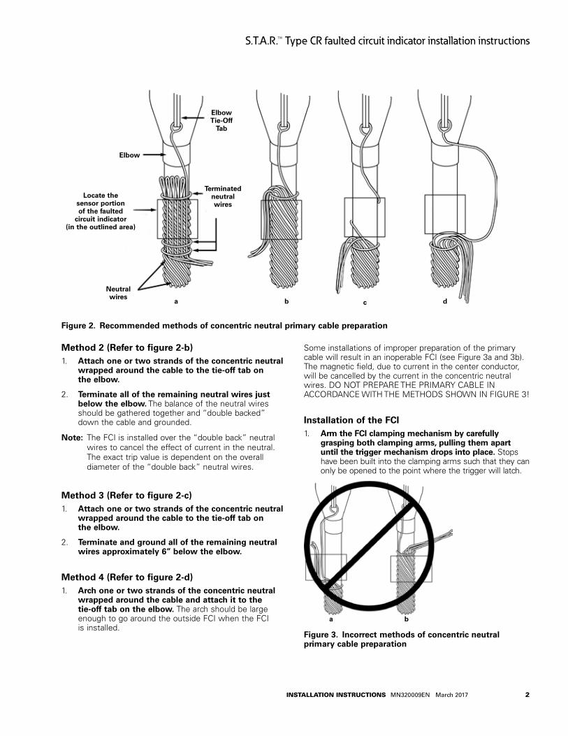
Figure 2 . Recommended methods of concentric neutral primary cable preparation
Method 2 (Refer to figure 2-b)1. Attach one or two strands of the concentric neutral
wrapped around the cable to the tie-off tab on the elbow .
2. Terminate all of the remaining neutral wires just below the elbow . The balance of the neutral wires should be gathered together and “double backed” down the cable and grounded.
otee:N The FCI is installed over the “double back” neutral wires to cancel the effect of current in the neutral. The exact trip value is dependent on the overall diameter of the “double back” neutral wires.
Method 3 (Refer to figure 2-c)1. Attach one or two strands of the concentric neutral
wrapped around the cable to the tie-off tab on the elbow .
2. Terminate and ground all of the remaining neutral wires approximately 6” below the elbow .
Method 4 (Refer to figure 2-d)1. Arch one or two strands of the concentric neutral
wrapped around the cable and attach it to the tie-off tab on the elbow . The arch should be large enough to go around the outside FCI when the FCI is installed.
Some installations of improper preparation of the primary cable will result in an inoperable FCI (see Figure 3a and 3b). The magnetic field, due to current in the center conductor, will be cancelled by the current in the concentric neutral wires. DO NOT PREPARE THE PRIMARY CABLE IN ACCORDANCE WITH THE METHODS SHOWN IN FIGURE 3!
Installation of the FCI1. Arm the FCI clamping mechanism by carefully
grasping both clamping arms, pulling them apart until the trigger mechanism drops into place . Stops have been built into the clamping arms such that they can only be opened to the point where the trigger will latch.
Figure 3 . Incorrect methods of concentric neutral primary cable preparation
Elbow
Locate the sensor portion of the faulted
circuit indicator (in the outlined area)
Neutral wires
Elbow Tie-Off
Tab
Terminated neutral wires
c da b
a b
2InstallatIon InstructIons MN320009EN March 2017
S.T.A.R.™ Type CR faulted circuit indicator installation instructions
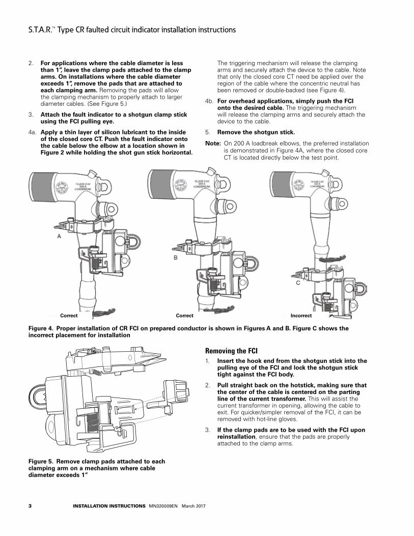
2. For applications where the cable diameter is less than 1”, leave the clamp pads attached to the clamp arms . On installations where the cable diameter exceeds 1”, remove the pads that are attached to each clamping arm . Removing the pads will allow the clamping mechanism to properly attach to larger diameter cables. (See Figure 5.)
3. Attach the fault indicator to a shotgun clamp stick using the FCI pulling eye .
4a. Apply a thin layer of silicon lubricant to the inside of the closed core CT . Push the fault indicator onto the cable below the elbow at a location shown in Figure 2 while holding the shot gun stick horizontal .
The triggering mechanism will release the clamping arms and securely attach the device to the cable. Note that only the closed core CT need be applied over the region of the cable where the concentric neutral has been removed or double-backed (see Figure 4).
4b. For overhead applications, simply push the FCI onto the desired cable . The triggering mechanism will release the clamping arms and securely attach the device to the cable.
5. Remove the shotgun stick .
otee:N On 200 A loadbreak elbows, the preferred installation is demonstrated in Figure 4A, where the closed core CT is located directly below the test point.
Figure 4 . Proper installation of CR FCI on prepared conductor is shown in Figures A and B . Figure C shows the incorrect placement for installation
Figure 5 . Remove clamp pads attached to each clamping arm on a mechanism where cable diameter exceeds 1”
Removing the FCI1. Insert the hook end from the shotgun stick into the
pulling eye of the FCI and lock the shotgun stick tight against the FCI body .
2. Pull straight back on the hotstick, making sure that the center of the cable is centered on the parting line of the current transformer . This will assist the current transformer in opening, allowing the cable to exit. For quicker/simpler removal of the FCI, it can be removed with hot-line gloves.
3. If the clamp pads are to be used with the FCI upon reinstallation, ensure that the pads are properly attached to the clamp arms.
IncorrectCorrect Correct
3 InstallatIon InstructIons MN320009EN March 2017
S.T.A.R.™ Type CR faulted circuit indicator installation instructions
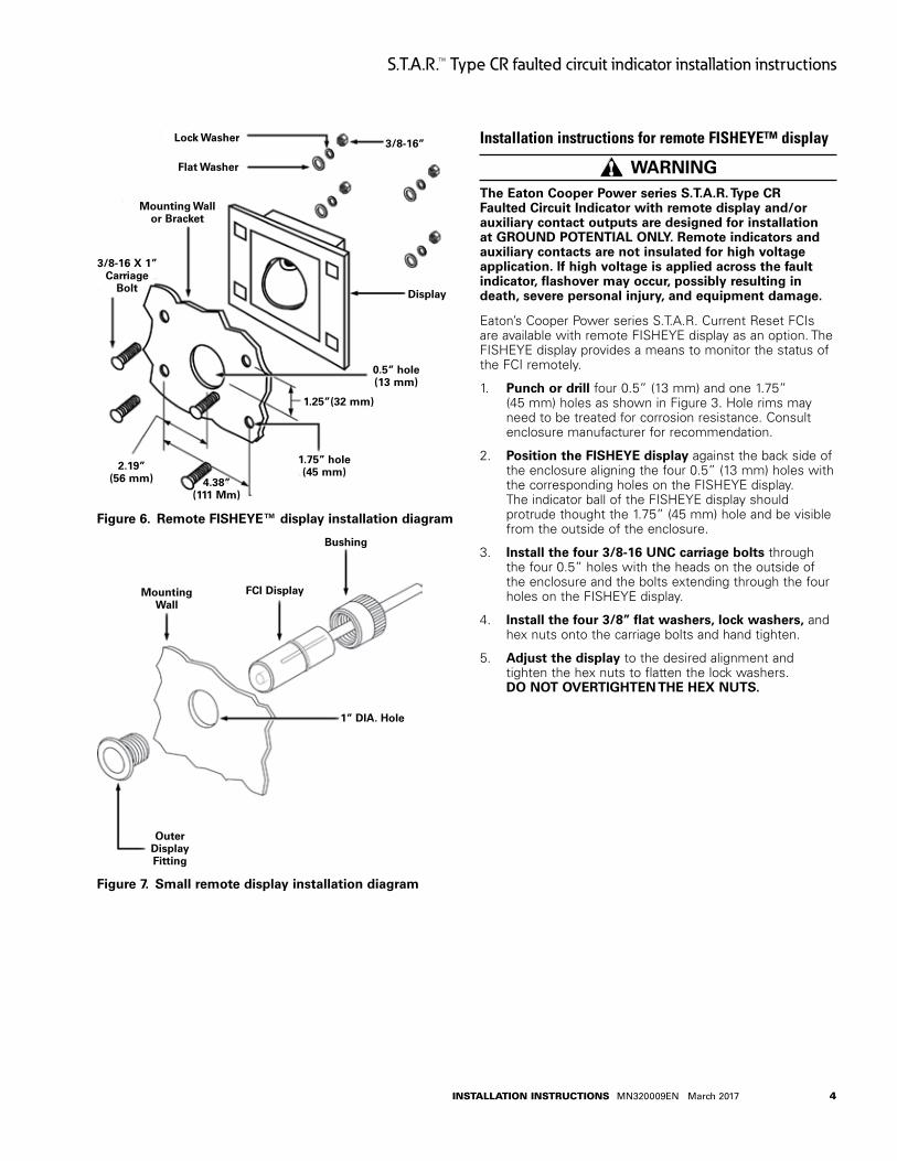
Figure 6 . Remote FISHEYE™ display installation diagram
Figure 7 . Small remote display installation diagram
Installation instructions for remote FISHEYE™ display
WARNINGThe Eaton Cooper Power series S .T .A .R . Type CR Faulted Circuit Indicator with remote display and/or auxiliary contact outputs are designed for installation at GROuND POTENTIAL ONLY . Remote indicators and auxiliary contacts are not insulated for high voltage application . If high voltage is applied across the fault indicator, flashover may occur, possibly resulting in death, severe personal injury, and equipment damage .
Eaton’s Cooper Power series S.T.A.R. Current Reset FCIs are available with remote FISHEYE display as an option. The FISHEYE display provides a means to monitor the status of the FCI remotely.
1. Punch or drill four 0.5” (13 mm) and one 1.75” (45 mm) holes as shown in Figure 3. Hole rims may need to be treated for corrosion resistance. Consult enclosure manufacturer for recommendation.
2. Position the FISHEYE display against the back side of the enclosure aligning the four 0.5” (13 mm) holes with the corresponding holes on the FISHEYE display. The indicator ball of the FISHEYE display should protrude thought the 1.75” (45 mm) hole and be visible from the outside of the enclosure.
3. Install the four 3/8-16 uNC carriage bolts through the four 0.5” holes with the heads on the outside of the enclosure and the bolts extending through the four holes on the FISHEYE display.
4. Install the four 3/8” flat washers, lock washers, and hex nuts onto the carriage bolts and hand tighten.
5. Adjust the display to the desired alignment and tighten the hex nuts to flatten the lock washers. DO NOT OVERTIGHTEN THE HEX NuTS .
Lock Washer
Flat Washer
3/8-16”
Mounting Wall or Bracket
3/8-16 X 1” Carriage
Bolt Display
2 .19”(56 mm) 4 .38”
(111 Mm)
0 .5” hole (13 mm)
1 .25”(32 mm)
1 .75” hole(45 mm)
Mounting Wall
FCI Display
Bushing
1” DIA . Hole
OuterDisplay Fitting
4InstallatIon InstructIons MN320009EN March 2017
S.T.A.R.™ Type CR faulted circuit indicator installation instructions
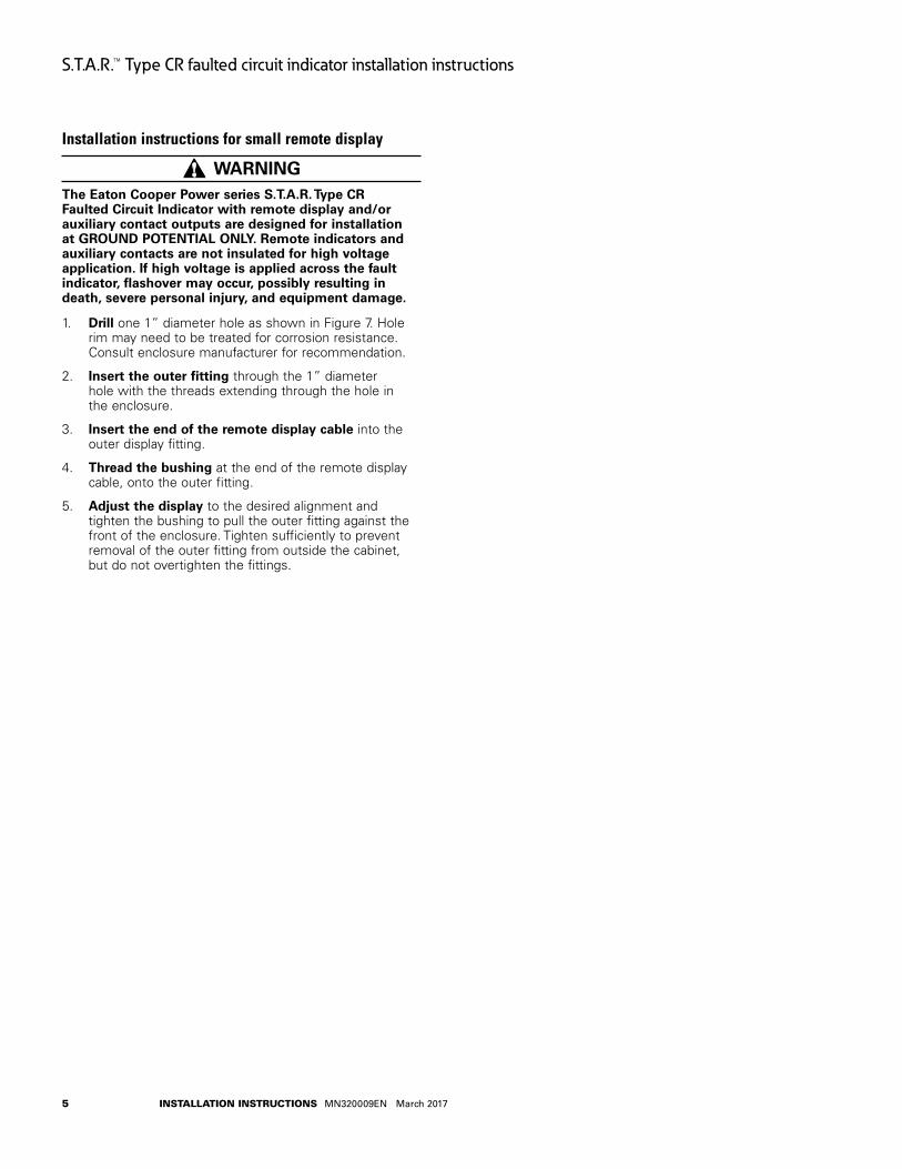
Installation instructions for small remote display
WARNING The Eaton Cooper Power series S .T .A .R . Type CR Faulted Circuit Indicator with remote display and/or auxiliary contact outputs are designed for installation at GROuND POTENTIAL ONLY . Remote indicators and auxiliary contacts are not insulated for high voltage application . If high voltage is applied across the fault indicator, flashover may occur, possibly resulting in death, severe personal injury, and equipment damage .
1. Drill one 1” diameter hole as shown in Figure 7. Hole rim may need to be treated for corrosion resistance. Consult enclosure manufacturer for recommendation.
2. Insert the outer fitting through the 1” diameter hole with the threads extending through the hole in the enclosure.
3. Insert the end of the remote display cable into the outer display fitting.
4. Thread the bushing at the end of the remote display cable, onto the outer fitting.
5. Adjust the display to the desired alignment and tighten the bushing to pull the outer fitting against the front of the enclosure. Tighten sufficiently to prevent removal of the outer fitting from outside the cabinet, but do not overtighten the fittings.
5 InstallatIon InstructIons MN320009EN March 2017
S.T.A.R.™ Type CR faulted circuit indicator installation instructions
This page intentionally left blank.
6InstallatIon InstructIons MN320009EN March 2017
S.T.A.R.™ Type CR faulted circuit indicator installation instructions

This page intentionally left blank.
7 InstallatIon InstructIons MN320009EN March 2017
S.T.A.R.™ Type CR faulted circuit indicator installation instructions
Eaton is a registered trademark.
All trademarks are property of their respective owners.
For Eaton’s Cooper Power series product information call 1-877-277-4636 or visit: www.eaton.com/cooperpowerseries.
!SAFETYFOR LIFE
Eaton1000 Eaton BoulevardCleveland, OH 44122United StatesEaton.com
Eaton’s Power Systems Division2300 Badger DriveWaukesha, WI 53188United StatesEaton.com/cooperpowerseries
© 2017 EatonAll Rights ReservedPrinted in USAPublication No. MN320009EN March 2017#5000050827 Rev. 04


![Submission Slide 1 Project: IEEE P802.15 Working Group for Wireless Personal Area Networks (WPANs) Submission Title: [Smart Grid: Faulted Circuit Indicator]](https://static.documents.pub/doc/80x56/5697bf761a28abf838c80d8e/submission-slide-1-project-ieee-p80215-working-group-for-wireless-personal.jpg)


