PRINCIPLES OF MULTIPHASE MEASUREMENTS November 30, 2004 State of Alaska Alaska Oil & Gas Conservation Commission Prepared by: Parviz Mehdizadeh, Ph.D. Production Technology Inc. Jane Williamson, P.E. Alaska Oil and Gas Conservation Commission Information Document to accompany “Guidelines For Qualification of Multiphase Metering Systems for Well Testing”, November 30, 2004
Transcript
PRINCIPLES OF MULTIPHASE MEASUREMENTS November 30, 2004
State of Alaska
Alaska Oil & Gas Conservation Commission
Prepared by:
Parviz Mehdizadeh, Ph.D. Production Technology Inc.
Jane Williamson, P.E. Alaska Oil and Gas Conservation Commission
Information Document to accompany
“Guidelines For Qualification of Multiphase Metering Systems for Well Testing”, November 30, 2004
Principles of Multiphase Measurements Parviz Mehdizadeh, Production Technology Inc 11/30/04 Jane Williamson, AOGCC
7.0 Wet Gas Metering Techniques ............................................. 13 7.1 Classification of Wet Gas ..............................................................13 7.2 Type 1 Wet Gas Meters.................................................................15 7.3 Type 2 Wet Gas Meters.................................................................16 7.4 Type 3 Wet Gas Meters.................................................................17
8.0 Multiphase Meter Performance............................................ 17 8.1 Specifying Accuracy and Uncertainty ............................................17 8.2 Preferred Method to Describe Accuracy........................................17 8.3 Performance Data and Field Tests ................................................18 8.4 Impact of GVF and WC on Performance .......................................18 8.5 Graphical Presentation of Multiphase Performance ......................20
Principles of Multiphase Measurements Parviz Mehdizadeh, Production Technology Inc 11/30/04 Jane Williamson, AOGCC
3 -30
Principles of Multiphase Measurements
1.0 Overview 1.0.1 Multiphase metering techniques were developed to improve upon
certain measurement limitations of conventional two and three-phase metering systems requiring gravity based test separators. Well tests are conducted routinely to monitor the flow rates from wells and forecast production. The well test data are used for reservoir management, production diagnostics and field allocation. To obtain accurate and consistent test results from conventional well testing systems, the equipment requires high maintenance, field personnel intervention, and time to perform tests.
1.0.2 Operators have looked at the multiphase metering technology as a method for reducing the cost of well tests and improving the quality of the well tests. Since multiphase metering systems can operate without the need for phase separation or with partial separation, they can be made into compact and lightweight systems. The small footprints and lightweight advantages can produce significant savings, especially in operational areas such as the North Slope and offshore where size and weight may result in additional installation costs.
1.0.3 A number of operators on the North Slope are looking at multiphase meter technology as an alternative to conventional gravity based test separators. BP Exploration (Alaska), Inc. (BPXA) and ConocoPhillips Alaska, Inc. have conducted field trials of a number of commercially available multiphase meters in Prudhoe Bay Unit and Kuparuk River Unit pools to assess their effectiveness in current operations as well as future asset developments.
1.0.4 The AOGCC, Department of Natural Resources (DNR) and Department of Revenue (DOR) sponsored a multiphase metering workshop, conducted in Anchorage on May 23, 2002, to assess the application of this technology to well testing and field allocation operations in Alaska. This seminar and follow up reviews by AOGCC have indicated that the multiphase metering techniques may be acceptable as a means of obtaining improved well testing
Principles of Multiphase Measurements Parviz Mehdizadeh, Production Technology Inc 11/30/04 Jane Williamson, AOGCC
4 -30
data. Furthermore the field wide deployment of this technology (1)∗
has the potential for improved reservoir management and reduction in facility costs required for well testing as noted by the recent Society of Petroleum Engineers papers listed in references 2-4.
1.0.5 Currently, there are few guidelines or standards available to train and direct the operator and AOGCC on how to qualify these new measurement techniques. To bridge this gap for Alaska operations, the AOGCC published “Guidelines for Qualification of Multiphase Metering Systems for Well Testing.” Industry and vendors who have potential application of multiphase meter systems were given opportunity to comment on the guidelines, planned for adoption as the process by which the AOGCC will process applications for multiphase meter use. This document, “Principles of Multiphase Measurements” compliments the guidelines by providing a general overview and training document for the applicant and AOGCC personnel
2.0 Terms, Definitions, and Nomenclature
2.0.1 The term “multiphase metering” in its broadest interpretation can be used to refer to both wet gas metering, as well as, the measurement of oil, water, and gas portions of commingled streams, which is commonly referred to as “multiphase metering”. Whether one is conducting a “wet gas” or “multiphase” measurement can depend on which product – i.e. oil or gas - is the focus of the measurement, as well as, the type of equipment used.(2) This document addresses both wet gas and multiphase metering systems.
2.0.2 A number of terms and definitions are used in describing the multiphase flow and multiphase measurements within the industry. The terms and definitions listed in Appendix 2 are adopted from the “Handbook of Multiphase Metering”, developed by the Norwegian Society of Oil and Gas Measurement. (3)
∗ References are listed in Appendix 1
Principles of Multiphase Measurements Parviz Mehdizadeh, Production Technology Inc 11/30/04 Jane Williamson, AOGCC
5 -30
3.0 Standards and Publications No U.S. standard is currently available for the users and regulators in the application and qualification of the multiphase meters. (4) However, the following publications address aspects of the multiphase and wet gas metering, and should be reviewed for those pursuing multiphase meter use. 3.0.1 American Petroleum Institute - “Use of Sub-sea Wet-Gas
Flowmeters in Allocation Measurement Systems”, API Recommended Practice RP 85, August 28, 2002 (www.api.org/cat)
3.0.2 International Standards Organization - “Allocation of Gas and Condensate in the Upstream Area”, Draft version of Technical Report - ISOTC193-SC3-WG1, May 18, 2002. ([email protected])
3.0.3 The Norwegian Society for Oil and Gas Measurement – “Handbook of Multiphase Metering”, published by NFOGM, September 1995 (www.oilnet.no/nfogm)
3.0.4 Department of Trade and Industry, UK - “Guideline Notes For Petroleum Measurements Under The Petroleum (Production) Regulations”, Oil and Gas Division, UK, Issue 7 – December 2003. (www.og.dti.gov.uk/regulation.)
3.0.5 American Society of Mechanical Engineers- “Wet Gas Metering Guidelines”, ASME/MFC publication 19M, (in preparation). [email protected]
4.0 Performance of Multiphase Meters
The use of multiphase meters in field applications is in its relative infancy. There are few generally accepted standards for performance. Three different approaches have been used by industry to verify the performance of multiphase and wet gas meters. These approaches consist of:
4.0.1 Manufacturer sponsored testing either in a third party test loop or at the manufacturer’s facility. A number of joint industry studies have been conducted to establish that these meters can perform to the specifications and capabilities claimed by the manufacturers. (7) The National Engineering Laboratory (NEL) in the UK, the K-Lab Wet Gas loop in Norway and the Colorado Engineering Experiment Station (CEESI) in the US have conducted a number of joint
Principles of Multiphase Measurements Parviz Mehdizadeh, Production Technology Inc 11/30/04 Jane Williamson, AOGCC
6 -30
industry projects to characterize the performance of multiphase flow meters. The results are not published but released to Joint Industry Project (JIP) participants and the multiphase meter manufacturers, who can share the data with their clients.
4.0.2 Third party testing where vendors and end users are not involved. These tests are generally conducted in a test loop under controlled conditions.
4.0.3 End-user field-testing where the multiphase meter is tested against conventional test separators. Many of these tests compare and index the performance of the multiphase meters to gravity based two or three phase test separators. The owner companies conducting the tests generally release the results to the JIP participants and the multiphase meter manufacturer. Some results have been published. (8-20)
5.0 Principles of Multiphase Measurements
The primary information required in the measurement of oil or gas multiphase flow streams includes flow rates of oil, water, and gas. The ideal method to obtain this data is to have a multiphase flow meter that would make direct and independent flow rate measurements of these components. Unfortunately, such a device does not exist as yet. Consequently, much of the extensive development in multiphase metering has been directed toward inferential techniques that use the instantaneous velocity and cross sectional fraction of each component to make these measurements. The following section will examine the application of these techniques as applied to multiphase meters used for oil, water and gas measurements.
5.1 Phase Velocity and Phase Fraction Measurements 5.1.1 For single-phase liquid or gas travelling through a pipe of cross
sectional area A at an average velocity V, the volumetric flow rate Q can be calculated by:
Q = AV (1)
5.1.2 When an oil, water and gas mixture is flowing through the same pipe, the calculations of the volumetric flow rates are complicated.
Principles of Multiphase Measurements Parviz Mehdizadeh, Production Technology Inc 11/30/04 Jane Williamson, AOGCC
7 -30
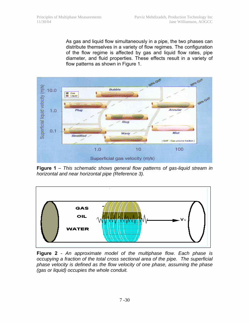
As gas and liquid flow simultaneously in a pipe, the two phases can distribute themselves in a variety of flow regimes. The configuration of the flow regime is affected by gas and liquid flow rates, pipe diameter, and fluid properties. These effects result in a variety of flow patterns as shown in Figure 1.
Figure 1 – This schematic shows general flow patterns of gas-liquid stream in horizontal and near horizontal pipe (Reference 3).
Figure 2 - An approximate model of the multiphase flow. Each phase is occupying a fraction of the total cross sectional area of the pipe. The superficial phase velocity is defined as the flow velocity of one phase, assuming the phase (gas or liquid) occupies the whole conduit.
Principles of Multiphase Measurements Parviz Mehdizadeh, Production Technology Inc 11/30/04 Jane Williamson, AOGCC
8 -30
5.1.3 A simple approach to estimate the volumetric flow rates for each phase is to establish the distribution of each phase (as illustrated in Figure 2) by assuming that each phase is occupying a fraction of the total cross-sectional area at any instant, which is determined by the following relationships:
fO = Ao/A, fW=Aw/A, fg =Ag /A (2)
fO+fW+fg = 1 (3)
Where fO, fW, and fg are the volume fractions (fraction of cross sectional area A) of the oil, water, and gas phases in the mixture.
5.1.4 The volumetric flow rate Q of each phase and the total (mixture) flow rate are then determined by:
Qo = A fo Vo , Qw =A fwVw , Qg = A fg Vg (4)
Qt = Qo+Qw+Qg (5)
Where Vo, Vw, and Vg are the superficial velocities of the oil, water, and gas phases in the mixture. The task of any multiphase meter is to estimate the volume fractions and the individual phase velocity in the above equations.
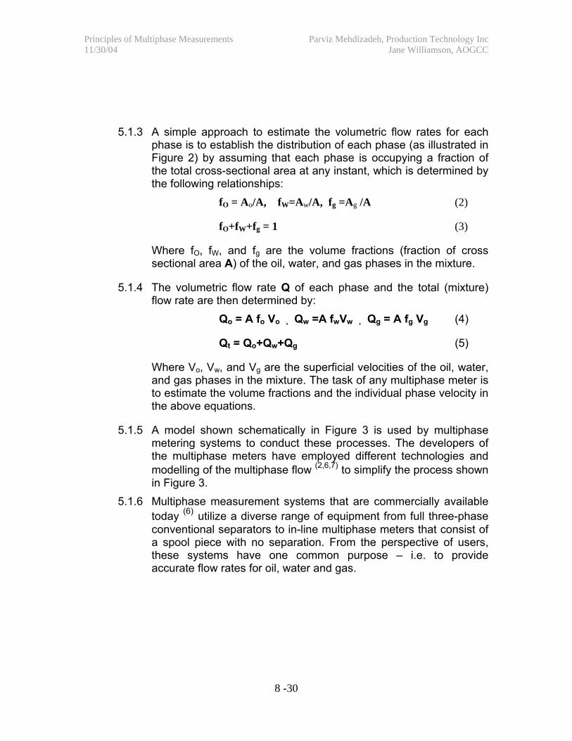
5.1.5 A model shown schematically in Figure 3 is used by multiphase metering systems to conduct these processes. The developers of the multiphase meters have employed different technologies and modelling of the multiphase flow (2,6,7) to simplify the process shown in Figure 3.
5.1.6 Multiphase measurement systems that are commercially available today (6) utilize a diverse range of equipment from full three-phase conventional separators to in-line multiphase meters that consist of a spool piece with no separation. From the perspective of users, these systems have one common purpose – i.e. to provide accurate flow rates for oil, water and gas.
Principles of Multiphase Measurements Parviz Mehdizadeh, Production Technology Inc 11/30/04 Jane Williamson, AOGCC
9 -30
1-Uncerta inty Reductio n– M ixing or Sepa ratio n
2-Fractio n Measurements -
Gas/Liquid Oil/Water @ P, T
3-Flo w Rates M ass/Volumetric
R ates @ P, T
4-M ode ling : Each Of The Above Processes Fluid Pro pertie s Corrections: Salinity, G rav ity,
Temperature , e tc. Conversio n Fro m M easured to S TD Co nditio ns
D ensity Die lectric IR , Sonic
Others
Venturi X-Co rre latio n
Coriolis Others
Inle t: M ultiphase
Flo w
Output - oil, wa ter, gas flo w rates
Figure 3 - Processes shown schematically in this figure are used in a multiphase metering system to obtain single-phase flow rates from a multiphase stream.
5.1.7 Processes that are shown in Figure 3 consist of some type of fluid conditioning, mixture density determination, mixture rate determination, mixture composition determination, and application of a flow model. These functions can be supplied by an instrument or by an assumption in a model.
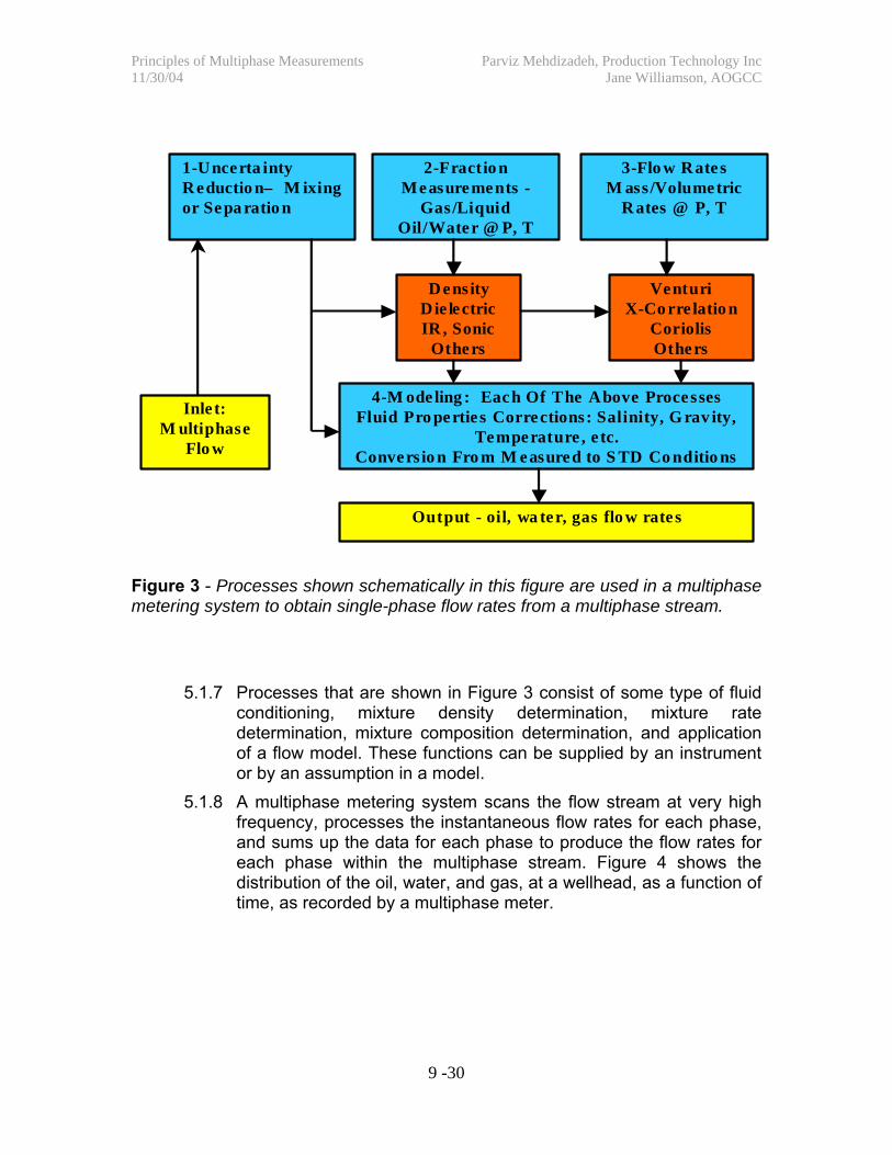
5.1.8 A multiphase metering system scans the flow stream at very high frequency, processes the instantaneous flow rates for each phase, and sums up the data for each phase to produce the flow rates for each phase within the multiphase stream. Figure 4 shows the distribution of the oil, water, and gas, at a wellhead, as a function of time, as recorded by a multiphase meter.
Principles of Multiphase Measurements Parviz Mehdizadeh, Production Technology Inc 11/30/04 Jane Williamson, AOGCC
10 -30
Figure 4 - Distribution of oil (green), water (blue), and gas (red) flow rates in real time at a wellhead as recorded by a multiphase flow meter.
6.0 Classification of Multiphase Meters
6.0.1 There is currently no “commonly-accepted” method of classifying multiphase meters. The following classification is proposed for this document until a “standard” classification system becomes available. In this classification, the metering systems are grouped in terms of methods by which the gas and liquid components are handled. 6.0.1.1 In Group I systems, one or more phases are completely
separated then measured. The separated streams may or may not be recombined to form the original stream. This category includes gravity or centrifugal based separation systems.
6.0.1.2 In Group II systems, the main flow stream is divided into “gas rich” and “liquid rich” streams, generally using separation based on a centrifugal process. Each stream is
0 100
200
300 4 00 500 600 700 800 900
1000
0:00 1:12 2:24 3:36 4:48 6:00 7:12 8:24 9:36
Time, hours
B P D
MACFD
QO BPDQW BPDQG MACFD
- 92
- 90
- 88
- 86
- 84
- 82
- 80
Principles of Multiphase Measurements Parviz Mehdizadeh, Production Technology Inc 11/30/04 Jane Williamson, AOGCC
11 -30
subjected to multiphase measurements then recombined to form the original stream.
6.0.1.3 In Group III systems, all three phases go through a single conduit and are measured at the same time. This category includes all the so-called inline meters. These meters may use some form of flow conditioning – i.e. use of elbow, mixers, etc.
6.1 Measurement Techniques
In each group, different measurement techniques, combination of techniques, and strategies can be used to obtain phase velocity and phase fraction information. Some typical examples of these techniques are shown in Table 1. For a more comprehensive discussion of these techniques, and how they are utilized in commercially available multiphase metering systems, the reader should consult references 2 and 6.
Table 1 Measurement Techniques and Devices Used to Obtain Phase Velocity and Phase Composition in Multiphase and Wet Gas
Principles of Multiphase Measurements Parviz Mehdizadeh, Production Technology Inc 11/30/04 Jane Williamson, AOGCC
12 -30
6.2 Multiphase Metering Installations
6.2.1 The AOGCC “Guidelines for Qualification of Multiphase Metering Systems for Well Testing” focuses on Groups II and III multiphase metering systems. However, it should be noted that Group I systems, which include 3-phase and 2-phase gravity-based test separators, are used in a majority of operations. The number of Group II and III installations (4) is about 1000, while the number of Group I installations is well over 10,000. Also, gravity-based test separators are the current “standard” of field measurement within the industry. All Group II and III installations are performance indexed against these systems in the field. Figure 5 shows four different multiphase metering systems in a field test loop.
Figure 5 – A field test loop that includes four different multiphase metering systems. From left to right- Agar MPFM 400, Roxar 1900VI, FMC FlowSys, and Schlumberger Venturi X.(21)
Principles of Multiphase Measurements Parviz Mehdizadeh, Production Technology Inc 11/30/04 Jane Williamson, AOGCC
13 -30
7.0 Wet Gas Metering Techniques
Wet gas metering covers a wide range of measurements, which is necessitated by the specific applications and the definition of “wet gas”. The definition of wet gas can vary depending on whether one is looking at the fluids from the perspectives of reservoir engineering, measurement systems, or commercial sales of the products. (7) Wet gas can be simply defined as gas, which contains some liquid. The amount of liquid can vary from a small amount of water to substantial amount of water and hydrocarbon. The amount and nature of the liquid, as well as the flow rate, temperature, and pressure of the flow stream can impact the selection and accuracy of the measurement system. It is therefore important that “wet gas” be characterized properly before one can discuss the wet gas measurement systems.
7.1 Classification of Wet Gas
7.1.1 A classification for different types of wet gas is proposed in reference 8. The proposed classifications, shown in Table 2, will be used in this document. This classification is based on superficial velocity (volumetric rate divided by the pipe cross sectional area) for gas and liquid and the Lockhart-Martinelli parameter, which is defined as:
X = (Vsl / Vsg) (√ρl / √ρg) (1)
Where X is the Lockhart-Martinelli number, Vsl and Vsg are the superficial velocity, and ρl and ρg are the density of liquid and gas respectively.
The gas volume fraction (GVF) of the stream can be obtained from the following equation:
GVF= 1/ [1+ X* (√ρg/√ρl)] (2)
The liquid to gas ratio (LGR) can also be calculated from Equation 1.
LGR=X*(√ρg/√ρl) (3)
Principles of Multiphase Measurements Parviz Mehdizadeh, Production Technology Inc 11/30/04 Jane Williamson, AOGCC
14 -30
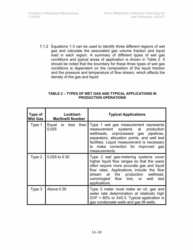
7.1.2 Equations 1-3 can be used to identify three different regions of wet
gas and calculate the associated gas volume fraction and liquid load in each region. A summary of different types of wet gas conditions and typical areas of application is shown in Table 2. It should be noted that the boundary for these three types of wet gas conditions is dependent on the composition of the liquid fraction and the pressure and temperature of flow stream, which affects the density of the gas and liquid.
TABLE 2 – TYPES OF WET GAS AND TYPICAL APPLICATIONS IN PRODUCTION OPERATIONS
Type of Wet Gas
Lockhart-Martinelli Number
Typical Applications
Type 1 Equal or less than 0.025
Type 1 wet gas measurement represents measurement systems at production wellheads, unprocessed gas pipelines, separators, allocation points, and well test facilities. Liquid measurement is necessary to make correction for improved gas measurements.
Type 2 0.025 to 0.30 Type 2 wet gas-metering systems cover higher liquid flow ranges so that the users often require more accurate gas and liquid flow rates. Applications include the flow stream at the production wellhead, commingled flow line, or well test applications.
Type 3 Above 0.30 Type 3 meter must make an oil, gas and water rate determination at relatively high GVF > 80% or X≥0.3. Typical application is gas condensate wells and gas lift wells.
Principles of Multiphase Measurements Parviz Mehdizadeh, Production Technology Inc 11/30/04 Jane Williamson, AOGCC
15 -30
7.2 Type 1 Wet Gas Meters
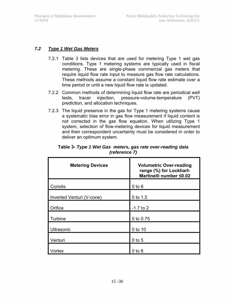
7.2.1 Table 3 lists devices that are used for metering Type 1 wet gas conditions. Type 1 metering systems are typically used in fiscal metering. These are single-phase commercial gas meters that require liquid flow rate input to measure gas flow rate calculations. These methods assume a constant liquid flow rate estimate over a time period or until a new liquid flow rate is updated.
7.2.2 Common methods of determining liquid flow rate are periodical well tests, tracer injection, pressure-volume-temperature (PVT) prediction, and allocation techniques.
7.2.3 The liquid presence in the gas for Type 1 metering systems cause a systematic bias error in gas flow measurement if liquid content is not corrected in the gas flow equation. When utilizing Type 1 system, selection of flow-metering devices for liquid measurement and their correspondent uncertainty must be considered in order to deliver an optimum system.
Table 3- Type 1 Wet Gas meters, gas rate over-reading data (reference 7)
Metering Devices Volumetric Over-reading range (%) for Lockhart-Martinelli number ≤0.02
Coriolis 0 to 6
Inverted Venturi (V-cone) 0 to 1.5
Orifice -1.7 to 2
Turbine 0 to 0.75
Ultrasonic 0 to 10
Venturi 0 to 5
Vortex 0 to 6
Principles of Multiphase Measurements Parviz Mehdizadeh, Production Technology Inc 11/30/04 Jane Williamson, AOGCC
16 -30
7.3 Type 2 Wet Gas Meters
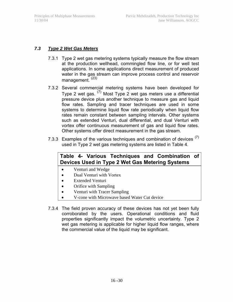
7.3.1 Type 2 wet gas metering systems typically measure the flow stream at the production wellhead, commingled flow line, or for well test applications. In some applications direct measurement of produced water in the gas stream can improve process control and reservoir management. (23)
7.3.2 Several commercial metering systems have been developed for Type 2 wet gas. (7) Most Type 2 wet gas meters use a differential pressure device plus another technique to measure gas and liquid flow rates. Sampling and tracer techniques are used in some systems to determine liquid flow rate periodically when liquid flow rates remain constant between sampling intervals. Other systems such as extended Venturi, dual differential, and dual Venturi with vortex offer continuous measurement of gas and liquid flow rates. Other systems offer direct measurement in the gas stream.
7.3.3 Examples of the various techniques and combination of devices (7) used in Type 2 wet gas metering systems are listed in Table 4.
Table 4- Various Techniques and Combination of Devices Used in Type 2 Wet Gas Metering Systems • Venturi and Wedge • Dual Venturi with Vortex • Extended Venturi • Orifice with Sampling • Venturi with Tracer Sampling • V-cone with Microwave based Water Cut device
7.3.4 The field proven accuracy of these devices has not yet been fully
corroborated by the users. Operational conditions and fluid properties significantly impact the volumetric uncertainty. Type 2 wet gas metering is applicable for higher liquid flow ranges, where the commercial value of the liquid may be significant.
Principles of Multiphase Measurements Parviz Mehdizadeh, Production Technology Inc 11/30/04 Jane Williamson, AOGCC
17 -30
7.4 Type 3 Wet Gas Meters 7.4.1 Metering systems used for Type 3 wet gas are multiphase metering
systems that were developed to measure flow streams composed of oil, water, and gas mixtures as was discussed in Section 6.
7.4.2 In field tests where the performance of the Type 3 wet gas and Group III multiphase meters have been compared to conventional test separators, uncertainty of 5-10% has been claimed. (21) Even uncertainty values as low as 2% have been claimed in some field tests. (7) It should be noted that these accuracy performances are obtained by comparing the gas flow measurements against conventional separators that generally use gas-metering devices described for Type 1 wet gas metering conditions. In many of the field tests these “reference” devices have questionable accuracy.
8.0 Multiphase Meter Performance
8.1 Specifying Accuracy and Uncertainty 8.1.1 Manufacturers and users have utilized different methods of
specifying and reporting the uncertainty (accuracy) for multiphase meters. Reference 2 provides a discussion of the various methods of describing the accuracy of a multiphase metering system, their advantages and limitations.
8.1.2 Users generally prefer to specify the accuracy in terms of percentage uncertainty relative to the flow rates of each phase – i.e. oil, water, and gas flow rates. This method is preferred by the AOGCC.
8.1.3 The uncertainty of the metering system can also be specified as a percentage relative to the total multiphase flow rate, which is called the “relative” uncertainty method. In certain measurement applications - e.g. trending or monitoring process changes at low flow rates, this may be an appropriate method for describing the accuracy (performance) of a multiphase metering system.
8.2 Preferred Method to Describe Accuracy 8.2.1 In the document “Guidelines for Qualification of Multiphase
Metering Systems for Well Testing“, the AOGCC requires that the percentage uncertainty of each phase be used to describe the
Principles of Multiphase Measurements Parviz Mehdizadeh, Production Technology Inc 11/30/04 Jane Williamson, AOGCC
18 -30
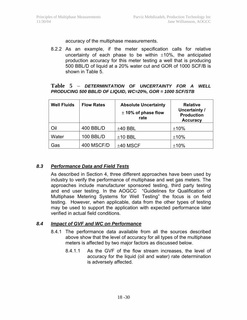
accuracy of the multiphase measurements. 8.2.2 As an example, if the meter specification calls for relative
uncertainty of each phase to be within ±10%, the anticipated production accuracy for this meter testing a well that is producing 500 BBL/D of liquid at a 20% water cut and GOR of 1000 SCF/B is shown in Table 5.
Table 5 – DETERMINTATION OF UNCERTAINTY FOR A WELL PRODUCING 500 BBL/D OF LIQUID, WC=20%, GOR = 1000 SCF/STB
Well Fluids
Flow Rates
Absolute Uncertainty
± 10% of phase flow rate
Relative Uncertainty / Production Accuracy
Oil 400 BBL/D ±40 BBL ±10%
Water 100 BBL/D ±10 BBL ±10%
Gas 400 MSCF/D ±40 MSCF ±10%
8.3 Performance Data and Field Tests
As described in Section 4, three different approaches have been used by industry to verify the performance of multiphase and wet gas meters. The approaches include manufacturer sponsored testing, third party testing and end user testing. In the AOGCC “Guidelines for Qualification of Multiphase Metering Systems for Well Testing” the focus is on field testing. However, when applicable, data from the other types of testing may be used to support the application with expected performance later verified in actual field conditions.
8.4 Impact of GVF and WC on Performance 8.4.1 The performance data available from all the sources described
above show that the level of accuracy for all types of the multiphase meters is affected by two major factors as discussed below. 8.4.1.1 As the GVF of the flow stream increases, the level of
accuracy for the liquid (oil and water) rate determination is adversely affected.
Principles of Multiphase Measurements Parviz Mehdizadeh, Production Technology Inc 11/30/04 Jane Williamson, AOGCC
19 -30
8.4.1.2 As the WC in the flow stream increases, it becomes more difficult for a multiphase metering system to achieve high levels of accuracy for the oil phase, which frequently is the major focus of the measurements.
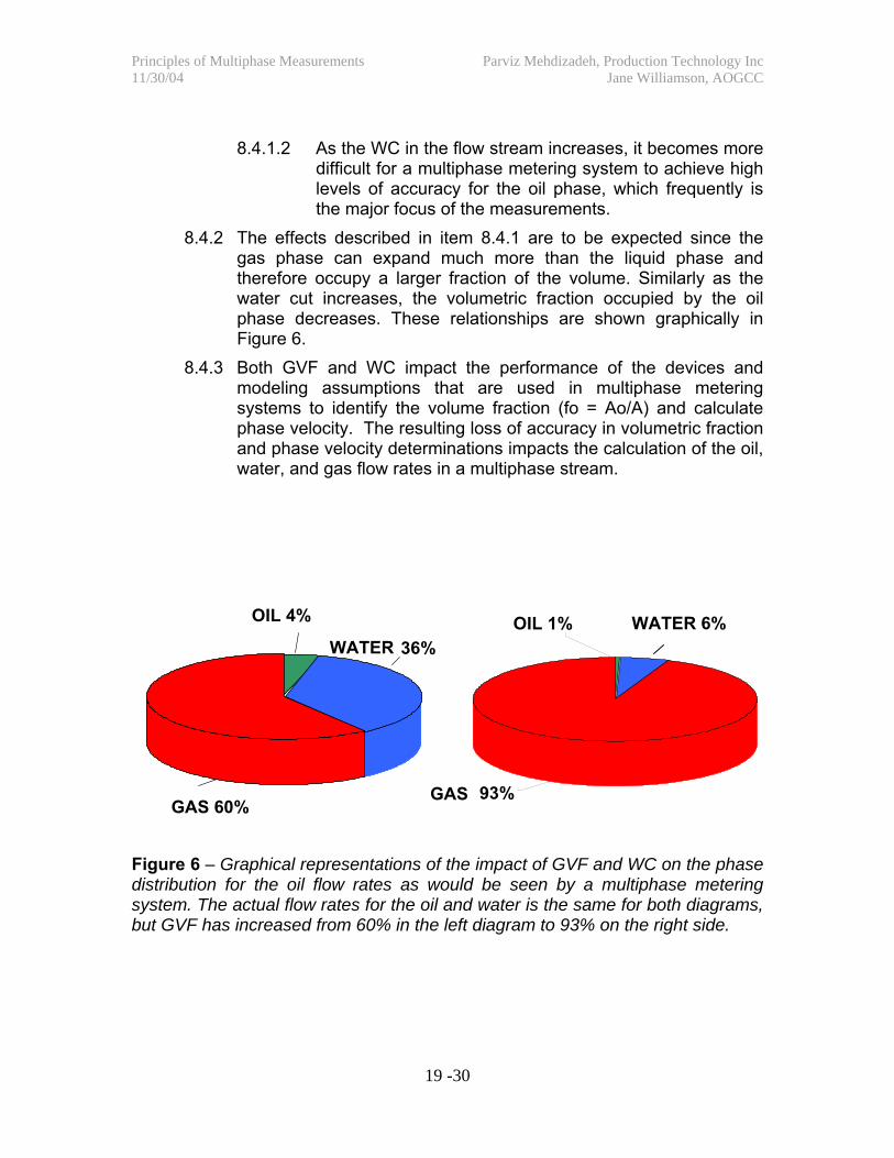
8.4.2 The effects described in item 8.4.1 are to be expected since the gas phase can expand much more than the liquid phase and therefore occupy a larger fraction of the volume. Similarly as the water cut increases, the volumetric fraction occupied by the oil phase decreases. These relationships are shown graphically in Figure 6.
8.4.3 Both GVF and WC impact the performance of the devices and modeling assumptions that are used in multiphase metering systems to identify the volume fraction (fo = Ao/A) and calculate phase velocity. The resulting loss of accuracy in volumetric fraction and phase velocity determinations impacts the calculation of the oil, water, and gas flow rates in a multiphase stream.
Figure 6 – Graphical representations of the impact of GVF and WC on the phase distribution for the oil flow rates as would be seen by a multiphase metering system. The actual flow rates for the oil and water is the same for both diagrams, but GVF has increased from 60% in the left diagram to 93% on the right side.
OIL 4%
WATER 36%
GAS 60% GAS 93%
OIL 1%
WATER 6%
Principles of Multiphase Measurements Parviz Mehdizadeh, Production Technology Inc 11/30/04 Jane Williamson, AOGCC
20 -30
8.5 Graphical Presentation of Multiphase Performance 8.5.1 A variety of methods have been used to graphically show the
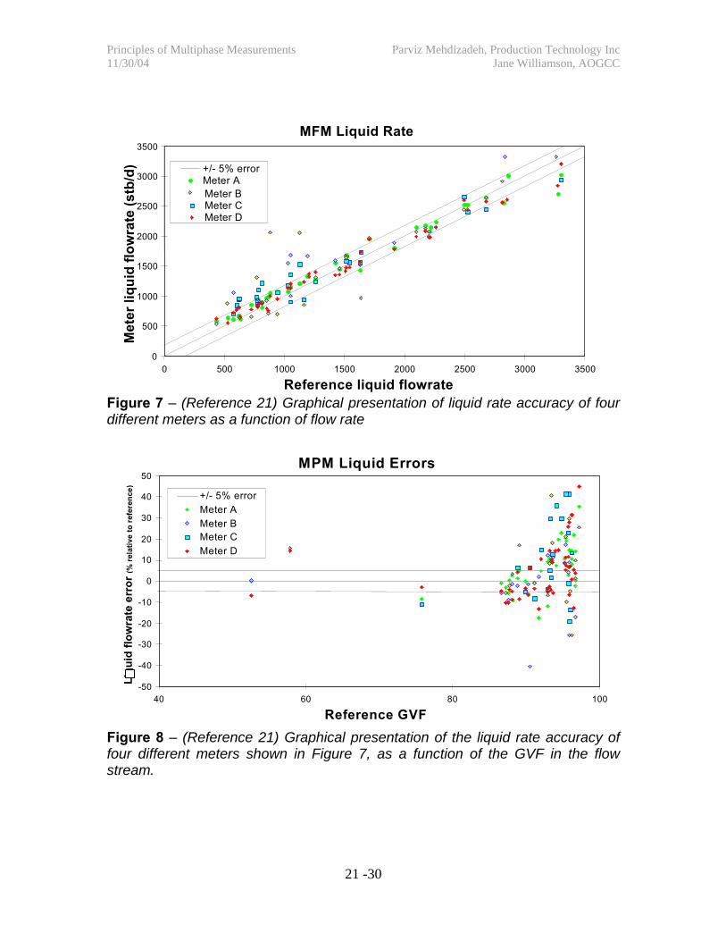
performance of the multiphase meters. Reference 22 describes these graphical methods, their advantages and limitations. The two most commonly used graphical presentations are shown in Figures 7 and 8.
8.5.2 Figure 7 shows the accuracy of liquid flow rate for four different multiphase meters. The dotted lines, in Figure 7, show the ±5% error band. The liquid (water and oil) flow rate measurements from the multiphase meters are compared with reference flow rate data, in this case obtained from a gravity based test separator. This type of plot is useful in showing if the liquid rate measurements for a certain multiphase meter can satisfy the ±5% accuracy level within the flow range shown in Figure 7.
8.5.3 Figure 8 shows the accuracy of the liquid flow rate for the same four multiphase meters, shown in Figure 7, in the so-called “two phase map”. In this type of graphical presentation one can see the impact of another parameter – i.e. GVF, on the accuracy of the four meters. The error bands show the capability of each meter to satisfy the ±5 accuracy requirement for liquid flow rates. This type of presentation is helpful to show not only the compliance of a meter with the accuracy requirement but also the effect upon accuracy as the GVF is increased. This “two phase map” type of graphical presentation can also be prepared to show the impact of other important factors such WC. This approach is especially helpful where the multiphase metering application is being considered for a large number of wells with wide range of GVF and WC values.
Principles of Multiphase Measurements Parviz Mehdizadeh, Production Technology Inc 11/30/04 Jane Williamson, AOGCC
21 -30
Figure 7 – (Reference 21) Graphical presentation of liquid rate accuracy of four different meters as a function of flow rate
Figure 8 – (Reference 21) Graphical presentation of the liquid rate accuracy of four different meters shown in Figure 7, as a function of the GVF in the flow stream.
MPM Liquid Errors
-50 -40 -30 -20 -10
0 10 20 30 40 50
40 60 80 100
Reference GVF
Liqu
id fl
owra
te e
rror
(% re
lativ
e to
refe
renc
e)
+/- 5% error Meter A Meter B Meter C Meter D
MFM Liquid Rate
0
500
1000
1500
2000
2500
3000
3500
0 500 1000 1500 2000 2500 3000 3500
Reference liquid flowrate
Met
er li
quid
flow
rate
(stb
/d) +/- 5% error
Meter A Meter B Meter C Meter D
Principles of Multiphase Measurements Parviz Mehdizadeh, Production Technology Inc 11/30/04 Jane Williamson, AOGCC
2. State of the Art Multiphase Flow Metering, American Petroleum Institute Publication 2566, 1st Edition, Committee on Petroleum Measurements, May 2004.
3. Dykesteen, Eivind, et al, Handbook of Multiphase Metering, Norwegian Society for Oil and Gas Measurement, published by NFOGM, September 1995.
4. Mehdizadeh P., “Status of MP and WG Metering,” presented at TAMU Multiphase Measurement Users Roundtable, Houston, May 7, 2003.
5. Theuvey, B. C. and Mehdizadeh, P., “Multiphase Flowmeters for Well and Fiscal Applications”, SPE 76766, presented at SPE Western Regional/AAPG Pacific Section Joint Meeting, Anchorage, May 20-22, 2002.
6. Falcone, G., et al, “Multiphase Flow Metering- Current Trends and Future Applications,” SPE 71474, presented at 2001 SPE-ATCE, New Orleans, September 30 – October, 2001.
7. Mehdizadeh P., Marrelli J., and Ting V.C., “Wet Gas Metering: Trends in Application and Technical Development,” SPE paper 77351, presented at SPE Annual Technical Conference and Exhibition, San Antonio, September 29-October 2, 2002.
8. Mehdizadeh P., Marrelli J., and Ting V.C., “Meter Designs Provide Wet-Gas Measurement Alternatives,” Oil&Gas Journal, March 24, 2003.
9. Stokes, Edward G., et al, “Application of The First Multiphase Flowmeter in The Gulf of Mexico,” SPE 49118, presented at Annual Technology Conference and Exhibition, New Orleans, September 27-30, 1998.
Principles of Multiphase Measurements Parviz Mehdizadeh, Production Technology Inc 11/30/04 Jane Williamson, AOGCC
23 -30
10. Kalsaas, Odd-Pedder, et al, “Operational Experience with Multiphase Meters at Vigdis,” presented at Multiphase Metering Workshop 2001 ASME –ETCE Conference, Houston, February 27, 2001.
11. Santamaria, G. and Noel, M.I., “Multiphase Flow Metering: the Mexican Experience,” presented at TAMU Multiphase Measurement User Roundtable, Houston, May 3, 2000.
12. Shen, Joseph, “Field Operation of a Compact Separation Multiphase Metering System,” presented at Multiphase Measurement & Production Testing User Roundtable, Houston, May 3, 2000.
13. Means S. R. and Mehdizadeh P., “New Technology Improves Well Testing Units,” Oil&Gas Journal, October 30, 2000.
14. Bortolin, Luigi, “Petrozuata’s Multiphase Metering Application,” presented at TAMU Multiphase Measurement User Roundtable, Houston, May 3, 2000.
15. Humphrey, A. I., et al, “Application of Multiphase Metering in Machar and Monan Fields,” OTC 12018, presented at 2000 Offshore Technology Conference, May 1-4, 2000, Houston.
16. Shen, Joseph, et al, “Field Evaluation of a Multiphase Meter in Well Testing Operation,” SPE 37436, presented at 1997 SPE Production Operations Symposium, Oklahoma City, March 9-11, 1997.
17. Ngai, Charles C., et al, “Performance Test of a High Gas Volume Fraction Multiphase Meter in a Producing Field,” SPE 38784, presented at 1997 SPE Annual Technical Conference and Exhibition, San Antonio, October 5-8, 1997.
18. Okland, O., et al, “Applications of Multiphase Meters at the Fullfaks Field in the North Sea”, OTC 8551, presented at 1997 Offshore Technology Conference, Houston, May 5-8, 1997.
19. Tuss, Bernie, et al, “Field Tests of the High Gas Volume Fraction Multiphase Meter,” SPE 36594, presented at 1996 SPE Annual Technical Conference and Exhibition, Denver, October 6-9, 1996.
20. Mohamad, P. G., et al, “Field Evaluation of Different Multiphase Flow Measurement Systems,” SPE 56585, presented at 1999 SPE-ATCE,
Principles of Multiphase Measurements Parviz Mehdizadeh, Production Technology Inc 11/30/04 Jane Williamson, AOGCC
24 -30
Houston, October 3-6, 1999.
21. Hasebe, B., Hall, A., Smith, B., Brady, J., and Mehdizadeh, P., “Field Qualification of Four Multiphase Flowmeters on North Slope, Alaska,” SPE 90037, presented at 2004 SPE-ATCE, Houston, September 27-29, 2004.
22. Scheers, Lex, “Multiphase and Wet Gas Flow Measurement”, presented at TAMU Multiphase Measurement Users Roundtable, May 8, 2004, Houston.
23. Haddelland, R., et al, “Online Measurement of Water in Wet Gas Flow,” presented at S.E. Asia Flow Measurement Workshop 2003.
24. “Sampling,” Manual of Petroleum Measurements Standards, Chapter 8, Section 8.2, American Petroleum Institute.
25. Guideline Notes For Petroleum Measurements Under The Petroleum (Production) Regulations, Issue 7 ed, Department of Trade and Industry, Oil and Gas Division, UK, December 2003.
Principles of Multiphase Measurements Parviz Mehdizadeh, Production Technology Inc 11/30/04 Jane Williamson, AOGCC
25 -30
Principles of Multiphase Measurements
Appendix 2 – Terms and Nomenclatures
The following terms and definitions are adopted from the “Handbook of Multiphase Metering”, developed by the Norwegian Society for Oil and Gas Measurement, published by NFOGM, September 1995
Emulsion: Colloidal mixture of two immiscible fluids, one being dispersed in the other in the form of fine droplets.
Flow regime: The physical geometry exhibited by a multiphase flow in a conduit; for example, liquid occupying the bottom of the conduit with the gas phase flowing above, or a liquid phase with bubbles of gas.
Fluid: A substance readily assuming the shape of the container in which it is placed; e.g. oil, gas, water or mixtures of these.
Gas: Hydrocarbons in the gaseous state at the prevailing temperature and pressure.
Gas-liquid-ratio (GLR): The gas volume flow rate, relative to the total liquid volume flow rate (oil and water), all volumes converted to volumes at standard pressure and temperature.
Gas-oil-ratio (GOR): The gas volume flow rate, relative to the oil volume flow rate, both converted to volumes at standard pressure and temperature.
Gas volume fraction (GVF): The gas volume flow rate, relative to the multiphase volume flow rate, at the pressure and temperature prevailing in that section. The GVF is normally expressed as a percentage.
Hold-up: The cross-sectional area locally occupied by one of the liquid phases of a multiphase flow relative to the cross-sectional area of the conduit at the same local position.
Homogeneous multiphase flow: A multiphase flow in which all phases are evenly distributed over the cross-section of a closed conduit; i.e. the composition is the same at all points.
Principles of Multiphase Measurements Parviz Mehdizadeh, Production Technology Inc 11/30/04 Jane Williamson, AOGCC
26 -30
Liquid-gas-ratio (LGR): The liquid volume flow rate (oil and water) relative to the total liquid volume flow rate (oil and water) at the pressure and temperature prevailing in that section.
Mass flow rate: The mass of fluid flowing through the cross-section of a conduit in unit time.
Multiphase flow: Two or more phases flowing simultaneously in a conduit. This document deals in particular with multiphase flows of oil, gas and water.
Multiphase flow rate: The total amount of the two or three phases of a multiphase flow flowing through the cross-section of a conduit in unit time. The multiphase flow rate should be specified as multiphase volume flow rate or multiphase mass flow rate.
Multiphase flow velocity: The flow velocity of a multiphase flow. It may also be defined by the relationship (Multiphase volume flow rate / Pipe cross-section).
Multiphase flow rate meter: A device for measuring the flow rate of a multiphase flow through a cross-section of a conduit. It is necessary to specify whether the multiphase flow rate meter measures the multiphase volume or mass flow rate.
Multiphase fraction meter: A device for measuring the phase area fractions of oil, gas and water of a multiphase flow through a cross-section of a conduit.
Multiphase meter: A device for measuring the phase area fractions and flow rates of oil, gas and water of a multiphase flow through a cross-section of a conduit. It is necessary to specify whether the multiphase meter measures volume or mass flow rates.
Oil: Hydrocarbons in the liquid state at the prevailing temperature and pressure conditions.
Oil-continuous multiphase flow: Multiphase flow of oil/gas/water characterized by the water phase distributed as water droplets surrounded by oil.
Phase: In reference to multiphase measurement - one constituent in a mixture of several. In particular, the term refers to oil, gas or water in a
Principles of Multiphase Measurements Parviz Mehdizadeh, Production Technology Inc 11/30/04 Jane Williamson, AOGCC
27 -30
mixture of any number of the three.
Phase area fraction: The cross-sectional area locally occupied by one of the phases of a multiphase flow, relative to the cross-sectional area of the conduit at the same local position.
Phase flow rate: The amount of one phase of a multiphase flow flowing through the cross-section of a conduit in unit time. The phase flow rate may be specified as phase volume flow rate or as phase mass flow rate.
Phase mass fraction: The phase mass flow rate of one of the phases of a multiphase flow, relative to the multiphase mass flow rate.
Phase velocity: The mean velocity of one phase of a multiphase flow at a cross-section of a conduit. It may also be defined by the relationship (Superficial phase velocity * Phase area fraction).
Phase volume fraction: The phase volume flow rate of one of the phases of a multiphase flow relative to the multiphase volume flow rate.
Slip: Term used to describe the flow conditions that exist when the phases have different velocities at a cross-section of a conduit. The slip may be quantitatively expressed by the phase velocity difference between the phases.
Slip ratio: The ratio between two-phase velocities.
Slip velocity: The phase velocity difference between two phases.
Superficial phase velocity: The flow velocity of one phase of a multiphase flow, assuming that the phase occupies the whole conduit by itself. It may also be defined by the relationship (Phase volume flow rate / Pipe cross-section).
Velocity profile: The mean velocity distribution of a fluid at a cross-section of a conduit. The velocity profile may be visualized by means of a two- or three-dimensional graph.
Void fraction: The cross-sectional area locally occupied by the gas phase of a multiphase flow relative to the cross-sectional area of the conduit at the same local position.
Volume flow rate: The volume of fluid flowing through the cross-section
Principles of Multiphase Measurements Parviz Mehdizadeh, Production Technology Inc 11/30/04 Jane Williamson, AOGCC
28 -30
of a conduit in unit time at the pressure and temperature prevailing in that section.
Water-continuous multiphase flow: A multiphase flow of oil/gas/water characterized by the oil phase being distributed as oil droplets surrounded by water. Electrically, the mixture acts as a conductor.
Water cut (WC): The water volume flow rate, relative to the total liquid volume flow rate (oil and water), both converted to volumes at standard pressure and temperature. The WC is normally expressed as a percentage.
Water-in-liquid ratio (WLR): The water volume flow rate, relative to the total liquid volume flow rate (oil and water) at the pressure and temperature prevailing in that section.
Water Volume Fraction (WVF): The water flow rate relative to the total volume flow rate at the local temperature and pressure. WVF is normally expressed as a percentage.
Principles of Multiphase Measurements Parviz Mehdizadeh, Production Technology Inc 11/30/04 Jane Williamson, AOGCC
29 -30
Principles of Multiphase Measurements
Appendix 3 – Installation Suggestions
Installation of multiphase measurement systems (multiphase and wet gas meters) should consider steps that would not only maximize the performance but also ease the verification and periodic testing (calibration) that may be necessary. These systems may require specific piping and fitting arrangements mechanical supports, and electrical equipment installation. Vendors generally provide this type of information to the users. Operators should require documentation from vendors on piping, installation description, electrical and instrument hook-ups, and accurate cabling requirements.
For the rest of this section the discussion will focus on Type 2 wet gas and Group II or III multiphase measurement systems. In a majority of field installations Group I multiphase meters – i.e. 2-phase and 3- phase gravity based test separators, are used to verify the performance of other multiphase measurement systems. While Group I multiphase meter installations are outside the scope of this document, when appropriate, issues related to their installations and performances are addressed. The following issues should be addressed in field installations for multiphase metering systems:
(a) For consistent performance, the metering system should be sized to cover the range (maximum and minimum instantaneous) of fluid rates expected.
(b) Complete system documentation including a detailed P&ID showing all instruments and set points and process conditions should be provided. The P&ID is helpful in identifying the location of critical system elements such as pipefitting, pressure and density measurement devices, control valves, and the operating set point.
(c) Gas breakout when flowing through single-phase liquid meters, used in Type I multiphase meters, causes inaccuracy. If the Group I system utilizes gravity separation equipment, the liquid discharge piping from this equipment to the liquid meters should be designed to eliminate gas breakout in liquid meters.
Principles of Multiphase Measurements Parviz Mehdizadeh, Production Technology Inc 11/30/04 Jane Williamson, AOGCC
30 -30
(d) Another cause for gas breakout in liquid meters is the pressure drop that occurs between the vessel and the meter. This gas breakout occurs if the liquid line pressure is below the last separation pressure
(e) If automatic samplers are used as a part of the multiphase metering system, reference 24 can be used to establish the requirements of velocity and flow conditioning that must be included in the sampler design and installation.
(f) Instrument wiring should be installed to minimize electrical noise including proper use of shielding, grounds, and electrical and radiation isolation.
(g) There are some special requirements if the multiphase meter utilizes a radiation-based source. These requirements include tracking of the radiation source and general worker safety. Tracking the radiation source can be done by the operator or through an approved third party contractor. These sources must be tracked on and off the property, as well as, to and from the property by a trained entity. While on the property, swab tests are performed for radiation leakage with the swab sent off for evaluation.
(h) Safety requirements and regulations related to item (g) may dictate the need for an individual on location who is trained in radiation awareness and safety. Workers in the area may require radiation awareness training.
(i) If a gamma densitometer is used in the multiphase metering system, field calibration may be necessary using the well water and gas at temperature and pressure. It is imperative that when calibrating the gas phase the meter be absolutely dry internally. The installation must consider ways of providing this capability.
(j) Wet gas meter accuracies are affected by the degree of insulation of the meter run and pressure taps from the meter body to the process instruments. (25) Pressure taps are especially affected by cooling which causes liquids to condense in the tapping line.