( 3} IE VEL MISCELLANEOUS PAPER GL-79-16 STATE OF THE ART OF UNDISTURBED SAMPLING OF COHESIONLESS SOILS by William F. Marcuson 111, Arley G. Franklin Geotedinical Laboratory U. S. Army Engineer Waterways Experiment Station P. 0. Box 631, Vicksburg, Miss. 39180 - oD DDC July 1979 i Final Report SEP1 1979 tJ Approved For Public Release; Distribulo L -L iteUU L R i .. S~ 4 . I - _Z44 r Prepared for Office, Chief of Engineers, U. S. Army C:) Washington, D. C. 20314 Under CWIS Work Units 31145 and 31619 C--t C= /Q #
Transcript
( 3} IE VELMISCELLANEOUS PAPER GL-79-16
STATE OF THE ART OF UNDISTURBEDSAMPLING OF COHESIONLESS SOILS
by
William F. Marcuson 111, Arley G. Franklin
Geotedinical LaboratoryU. S. Army Engineer Waterways Experiment Station
P. 0. Box 631, Vicksburg, Miss. 39180 -
oD DDCJuly 1979 i
Final Report SEP1 1979 tJApproved For Public Release; Distribulo L -L iteUU L R
i . . S~4 .I -
_Z44
r Prepared for Office, Chief of Engineers, U. S. ArmyC:) Washington, D. C. 20314
Under CWIS Work Units 31145 and 31619
C--tC= /Q #
Destroy this report when no longer needed. Do not returnit to the originator.
The findings in this report are not to be construed as an officialDepartment of the Army position unless so designated
by other authorized documents.
UnclassifiedSECURITY CLASSIFICATION OF THIS PAGE (Ohmn Does atau4________________
Approved for public release; distribution unlimited.
17. DISTRIGUTION STATEMENT (014 Srof eat Id I iff 280. 1II afilint *11.. Report)
0S. SUPPLEMENTARY NOTESThis report is essentially the same as a paper prepared and presented at theInternational Symposiums on Soil Sampling, sponsored by the International Societyfor Soil Mechanics and Foundation Engineering, in Singapore, July 19T9.
is. KEY WORDS (Comehow- on "oee~ wf "e.. 088ME nd~f "i ore. WOO
1 -4TACr f~MIDR 08 04FIVI ND 4M a fNWatf 4101 M104 Blai 61'An important phase of any major site investigation is the obtaining of
high-quality undisturbed samples of the subsurface materials.* This report de-scribes the current state of the art in obtaining undisturbed samples of cohe-sionless material--specifically, sands, silts, gravels, and mixtures--primarilyas it Is reflected in the experience of the Watervays Experiment Station-(yES) _and of others on the North American continent. - -_
(Continued)
OD F w 3 ENTN 4W I Nov a s semssLo Unclassified
SEDUIY CLNPCATIVI OF TW111 PAGE ObesDe 52;'5610
Unlaamified
SuCUmT CLASFICAT OF THIS PA0n~ Da
20. ABSTRACT (Continued).
- The report discusses general considerations in planning an undisturbedrampling program; methods of access to the soil materials for sampling, testing,or observationL ad. methods of sampling cohesionless soil. Methods of accessand methods of sampling are described in tables vhic h--so note the areas ofapplicabilit of the various methods, important li~itations and pi*falls, andimportant rferences. It offers further discuss6ns on speclal considerationsin methods'of sampling, such as characteristics of samplin !devices, drillingfluids, and sample intervalg; the care of soil samples; and evaluation ofsample disturbance.
It is concluded that: (a) high-quality, undisturbed samples of many sandscan be obtained with a fixed-piston sampler and drilling mud, with proper careand attention to details of sampling, handling, and transportation (this sam-pling process yields very good samples of medium dense sands, but tends todensify loose sands and loosen dense sands); (b) the use of radiographs isrecommended as a nondestructive method of evaluating sample disturbance; (c) ingravels, the only proven means of recovering undistuLbed samples is by hand-carving block samples; and (d) recent studies indicate that freezing in situ,followed by coring, offers a promise for obtaining undisturbed samples of muchhigher quality than is presently possible.
Unclassified
$SCUITY CLAlUFICATION OF THIS PAOS4bm Dw. h#on
Preface
The investigation reported herein was conducted at the U. S. Army
Engineer Waterways Experiment Station (WES) under the sponsorship of the
Office, Chief of Engineers, Department of the Army, as part of CWIS Work
Units 31145 entitled "Liquefaction of Dams and Foundations During Earth-
4 quakes," and 31619 entitled "Development of Technique and/or Device to
Evaluate Liquefaction Potential of In Situ Cohesionless Materials."
The work was performed and this report was prepared by Drs. W. F.
Marcuson III and A. G. Franklin, under the general supervision of
Dr. P. F. Hadala, Chief, Earthquake Engineering and Geophysics Division,
Geotechnical Laboratory (GL), and Mr. James P. Sale, Chief, GL, WES.
This report is essentially the same as a paper prepared and submitted to
the International Symposium on Soil Sampling, sponsored by the Interna-
tional Society for Soil Mechanics and Foundation Engineering, in
Singapore, July 1979.
COL John L. Cannon, CE, was Commander and Director of WES during
the preparation and publication of this report. Mr. F. R. Brown was
Technical Director.
N M A W 4. M EI "
Mst AIAL W~tSPE
Contents Pg
Preface .
Considerations in Planning an Undisturbed Sampling Program ... 4
Methods of Access for Sampling. .. ........ ........ 6
Methods of Sampling Cohesionless Soil. .. ... . .... ...... TSpecial Considerations in Methods of Sampling .. .. .. ...... 12
Care of Soil Samples. .. ........ . .... ........ 15
Evaluation of Sample Disturbance .. ..... ........... 16Conclusions and Recommendations. .. ... ............. 19
1. Preconstruction site investigations are required to determine
geotechnical conditions that affect the feasibility of a project and the
design, cost, performance, and ultimate safety of the structure. It is
necessary that they be adequate in terms of thoroughness, suitability
of methods used, and quality of execution of the work to assure that all
important conditions have been detected and reliably evaluated. An
important phase of any major site investigation is the obtaining of high-
quality undisturbed samples of the subsurface materials. The purpose
of this paper is to describe the current state of the art in obtaining
undisturbed samples of cohesionless material--specifically, sands, silts,
gravels, and mixtures. The viewpoint of the writers is, of course, most
strongly influenced by the experience of the U. S. Army Engineer Water-
ways Experiment Station (WES) and of others on the North American con-
tinent. Other views of the current state of the art may be found in
papers presented at the Annual Convention of the American Society of
Civil Engineers (1978).
2. The need for high-quality undisturbed samples of cohesionless
soils has been highlighted in recent years by increasing awareness of
the need to evaluate the seismic stability (previously referred to inthe literature as the liquefaction potential) of soils in the foundations
of important structures such as nuclear power plants and earth dams.
In order to evaluate the seismic stability of cohesionless soils, high-
quality undisturbed soil samples are needed for the laboratory deter-
mination of cyclic strength and for accurate determination of in situ
density. Consequently, it is necessary to preserve, as well as possible,
both the in situ density and the in situ soil structure, including grain-
to-grain contacts, with a minimum of disturbance. The in situ density
and the in situ structure are separate and distinct properties of the
soil. Preservation of the in situ density does not necessarily imply
preservation of the in situ structure, and both must be preserved if
laboratory test results are to be truly representative of the soil be-
havior in situ.
3. There is no such thing as a truly undisturbed sample, primarily
for two reasons: (1) a sampling tube displaces a certain amount of soil,
which inevitably produces strain and some disturbance of the sample;
and (2) even in "perfect sampling," an imaginary process that eliminates
disturbance due to soil displacement, the state of stress in the soil
sample undergoes a complex, and to some degree indeterminate, history
of change during the sampling, handling, shipping, storage, extrusion,
specimen preparation, and laboratory setup processes. Moreover, the in
situ state of stress, stress history, and state of stress in the sample
are seldom known except by crude approximation. These shortcomings are
widely recognized, and the term "undisturbed" sample is conventionally f
used to mean a sample that is obtained and handled by methods designed
to minimize these effects.
4. Even a cursory review of the literature on soil sampling shows
that the most important work in the area is that of M. Juul Hvorslev.
His monograph entitled "Subsurface Exploration and Sampling of Soils for
Civil Engineering Purposes," published in 1949, is the classic work in
soil sampling, and after three decades remains the fundamental reference
on subsurface soil exploration for students and practitioners of founda-
tion engineering.
Considerations in Planning an UndisturbedSampling Program
5. General requirements for subsurface investigations, including
drilling and sampling, are discussed in an American Society of Civil
Engineers (ASCE) Task Committee Report (1972). The undisturbed sampling
program normally should be preceded by a preliminary exploration program
that includes representative sampling, penetration resistance tests,
groundwater measurements, and surface surveys of the site, and may in-
clude (depending on the scope and importance of the project) geophysical
investigations, remote sensing studies, surface soil mapping, etc.
L4
These preliminary investigations define the soil profile, soil classifi-
cations, relative consistency of the various soil layers, groundwater
regime, and other site conditions.
6. From consideration of the soil conditions delineated in the
preliminary soil investigation, the geotechnical problems are identified
and the technical course of action is planned. On this basis, the lab-
oratory testing program is planned to provide the necessary geotechnical
P data for input to the analyses. The laboratory program in turn definest
the requirements for the undisturbed sampling program. Specific con-
siderations include depths, locations, number, and redundancy of the
*! samples to be obtained, and coordination of the laboratory and field
schedules to minimize storage time. (See Arman and McManis, 1976, for
a description of the effects of duration of storage on sample properties.)
7. The need to obtain undisturbed samples of cohesionless soils
is generally encountered when it is necessary to predict the seismic
stability of these soils during an earthquake. For this evaluation, the
results of stress-controlled, consolidated-undrained cyclic triaxialA, tests are generally used. The number of high-quality test specimens
needed for a typical laboratory cyclic testing program varies from 12 to
36 for each distinct material. The need for redundancy in sampling
should be recognized to allow for unavoidable and inadvertent losses
occurring at various phases from sampling to testing and for additional
testing needs that are recognized during the investigation. An appro-
priate degree of redundancy will eliminate the need for costly returns
to the field for additional samples.
8. The overriding consideration in sample size is the laboratory
testing requirement that the specimen diameter must be at least six
times the diameter of the maximum-size particle. If facilities do not
exist for testing specimens of such a size, there is no point in se-
curing undisturbed samples except for density determinations. Addi-
tionally, conditions such as equipment limitations, soil density, and
overburden pressure may be such that sample tubes of the required size
cannot be advanced in some materials. In this case, the only recourse
is to use test pits or other accessible excavations. In U. S. practice,
5
the smallest diameter sampler generally used for important projects is
a nominal 3 in. (7.6 cm) diameter.
9. Various methods and types of samplers are used in obtaining
undisturbed samples of granular soil, and it is the writers' experience
that there is no single method or tool that works in every case. Con-
sequently, in planning a sampling program for unfamiliar soil deposits,
provision should be made for the use of alternative methods or for an
experimental phase in the field program to identify the most successful
equipment and/or method of sampling.
Methods of Access for Sampling
10. Methods of access to the soil materials for sampling, testing,
or observation are listed in Table 1.
11. In most cases, access for sampling is provided by drilling,
and in North American practice rotary drilling or test pits are used for
important projects.
12. In most cohesionless materials that are free of boulders and
gravel particles, adequate undisturbed samples can be obtained from
boreholes with fixed-piston samplers using thin-wall metal tubes. Undis-
turbed samples of boulders, gravels, or sand-gravel mixtures generally
cainot be obtained from boreholes by means of presently available sam-
plers. Test pits, shafts, or other accessible excavations may be used
with hand-sampling methods where undisturbed samples are required.
However, this procedure is expensive and time-consuming, particularly
where the materials in question are below the groundwater table, in
which case, dewatering by means of well points or other suitable methods,
such as freezing, is required. Osterberg and Varaksin (1973) describe
a sampling program in sand in which an annular ring was frozen to permit
dewatering of the interior and excavation of a shaft for access to the
soil.
13. The dewatering and excavation process can greatly change thein situ state of stress in the material to be sampled. Changes in the
state of stress may produce significant changes in void ratio or density.
6
-t is important to remember that small shear strains can. result in large
changes in soil structure and consequently in the dynamic soil properties.
Efforts to determine the change in the state of stress as a result of
excavation and dewatering (including measurements of soil heave) are
worthwhile.
Methods of Sampling Cohesionless Soil
14. Methods and devices for obtaining undisturbed samples of
cohesionless soils are listed in Table 2.
15. No single sampling device or sampling procedure yields satis-
factory results in every cohesionless material. WES experience indi-
cates that, in general, the best choice of sampling device is governed
by the relative consistency of the material to be sampled. In loose
to medium dense sands, silts, and sand-silt mixtures, fixed-piston, thin-
wall tube samplers have the best chance of yielding high-quality un-
disturbed samples. Both the Hvorslev fixed-piston sampler and the
Osterberg hydraulic piston sampler are in this category.
16. An important consideration in the choice of samplers is the
control of sample disturbance by maintaining a specific recovery ratio*
of unity. The specific recovery ratio as an incremental quantity is
distinct from the total recovery ratio, which is the ratio of the total
length of sample recovered to the total length of sampler push. While
maintenance of a specific recovery ratio of 1.0 does not in itself as-
sure minimum disturbance of the soil, a specific recovery ratio other
than 1.0 clearly means that the sample has deformed and therefore is
disturbed. A notable advantage of the fixed-piston sampler is that un-
der most conditions the fixed piston provides positive control over the
specific recovery ratio during the push of the sampler.
17. Another advantage of the fixed piston, especially important
in sampling cohesionless soils, is that it produces a vacuum at the top
* The ratio of the increment of sample entering the tube to the incre-
ment of tube advance (Hvorslev, 1949).
7
of the sample in response -to any tendency for the sample to slip out of
the tube. For easy and gentle removal of the tube and sample from the
sampler, this vacuum should be relieved. The Hvorslev device has a con-
venient means of accomplishing this. While 4 vacuum release has not
been provided for on the Osterberg sampler, the vacuum can be relieved
by drilling a small hole near the top of the sample tube and below the
piston. A later version of the Osterberg sampler includes a vacuum re-
lease as well as other improvements (Osterberg, 1973). Other types of
piston samplers, including the so-called stationary piston samplers (see
Table 2), also provide the vacuum at the top of the sample, but lack
positive control of the specific recovery ratio.
18. The primary disadvantage of the Hvorslev sampler is that it
is complex in construction and operation, and therefore requires highly
skilled operators. Like most fixed-piston samplers, the Hvorslev sampler
requires an inner string of drill rods in addition to the normal drill
string. The inner rod string is clamped at the top of the boring to
provide fixity for the piston. With the Osterberg sampler, only the
normal single string of rods is required. The piston is fixed through
the sampler body to the drill string, which is clamped at the top of
the hole. The sample tube is advanced by hydraulic pressure applied
through drilling fluid pumped down the drill string.
19. In dense to very dense and/or cemented sands, silts, and sand-
silt mixtures, it may not be possible to push thin-walled tubes with
conventional tube samplers. If tubes can be pushed in such sands, the
samples obtained will be less dense than the in situ material (Potamology
Investigations Report No. 12-1, WES, 1952). If soil "Swples must be
obtained from boreholes, the Pitcher or Denison sampler should be con-
sidered. These samplers use core bits to assist in advancing the thin-
walled tubes. They have been used with varying degrees of success in
granular materials. They are most successful in soils with cementation
or material cohesion.
20. If soil samples are to be obtained from accessible excavations,
such as test pits or shafts, either hand-carved block samples or the
GEl sampler should be considered. This device, shown in Figure 1,
8
Figure 1. GEI sampler
consists of a tripod holder and a 7.6-cm-diameter brass Denison tube.
The sampling procedure begins with trimming the soil carefully for a
distance of about 0.5 cm ahead of the tube to a diameter slightly larger
than that of the tube. Then, light vertical pressure is applied by hand
to advance the tube, and the cutting edge shaves off the excess soil.
This procedure is repeated until the desired sample length is recovered.
Use of this method in cohesionless materials requires that they be
drained and possess apparent cohesion.
21. An indication of relative sample quality, as obtained in dense
sand with the GEI sampler and a fixed-piston sampler, can be seen in the
results of an investigation of Savannah River sand by the Corps of
9
Engineers. The sand was placed in a test fill and compacted by a vibra-
tory roller. Samples were initially taken with a fixed-piston sampler,
and were found to have an average dry density of 102 lb/ft' (1632 kg/m3),
compared to an average sand-cone dry density of 113 lb/ft3 (1808 kg/m3).
Samples later obtained from test pits with the GEl sampler had an aver-
age dry density of 105 lb/ft3 (1680 kg/m3 ). The difference in sample
quality is reflected in this modest difference in sample density and in
a dramatic difference in resistance to cyclic loading. As shown in
Figure 2, the cyclic resistance of the samples obtained with the GEl
sampler is an order of magnitude higher, in terms of the number of cycles
to 10 percent axial strain, than that of the samples taken with the
fixed-piston sampler, an indication that the in situ structure is better
preserved in these sands by sampling with the GEl sampler.
22. Samples suitable for density determinations, though not for
tests of mechanical properties, may sometimes by obtained from boreholes
with the help of chemical stabilization or impregnation (Karol, 1971;
Windisch and Soulie, 1970). However, such methods are not yet developed
to a degree that permits routine use. Special precautions are required
when toxic chemicals are involved. Also, it may not be permissible to
inject chemicals or grouts into aquifers. Useful discussions of methods
of sampling granular soils are given by Hvorslev (1949) and Barton (1974).
23. Recent studies (Yoshimi et al., 1978; Singh et al., 1978) on
freezing of sand samples in situ and in the laboratory indicate that,
if confining pressure is maintained and drainage is not impeded during
* Ifreezing, volume change during freezing is insignificant and the staticand dynamic soil strengths are not altered upon thawing. The necessary
drainage condition can be achieved by unsaturation, or in saturated
soils, by freezing in such a way that there is free drainage on the un-
frozen side of the freezing interface. The preliminary research results
cited suggest that the in situ structure of the soil can be preserved
essentially without disturbance by the use of freezing in situ followed
by sampling with a core drill, and thawing only after confining pressure
has been reapplied in the test cell. While this technique has not yet
been fully developed or proven by substantial field experience, it
10
0.46CLASSIFICATION: BROWN. POORLY0
GRADED SAND (SP)WITH MICA
0.40g0
0
0.36
0.-0
0.250
CYCLES TO 10 PERCENT DOUBLE AMPLITUDE AXIAL STRAIN
LEGEND
FIXEDGEI PITO TSF kPa
0 0 1.0 96A to 2.0
NOTE: ad, a CYCUIC DEVIATOR STRESS
ir EFFECTIVE HYDROSTATICCONFINING PRESSURE AT THEEND OF CONSOLIDATION
Figure 2. Cyclic triaxial test data forSavannah River sand
offers hope for obtaining undisturbed samples of much higher quality
than can be achieved with current practice.
Special Considerations in Methods of Sampling
24. In North American practice, characteristics of sampling devices
are typically described in terms of their geometrical properties, such
as the area ratio, Ca , and inside clearance ratio, Ci . Hvorslev
(1949) defines the area ratio as
D2 _ D
2
C = D e (1)a D2e
where
Dw = outside diameter of the tube that enters the soil duringsampling
D = inside diameter of the cutting edge of the sampling devicee
The area ratio is approximately equal to the ratio of the volume of
soil displaced by the sampler to the volume of the sample. In WES prac-
tice, it is considered that area ratios of 13 percent or less are accep-
table, but values of 10 percent or less are preferred. The inside
clearance ratio is defined by Hvorslev (1949) as
D -D
Ci = s e (2)D()e
where Ds = inside diameter of the sample tube . Inside clearance is
produced by swaging the cutting edge of the tube. This reduces the
friction between the sample and the inside wall of the tube during the
sampling process. Without this provision, friction would increase with
sampler penetration so that after a short advance no more soil would
enter the tube, or so much additional force would have to be applied to
advance the sampler that high stresses would be placed on the sample in
and Just below the tube. Depending on the in situ density, these would
either loosen or densify the material. Inside clearance also permits
lateral expansion of the sample after it enters the tube, and thus
12
produces disturbance of soil structure and reduction of density in dense
soils. To minimize expansion of the soil sample and accompanying distur-
bance, the smallest inside clearance ratio that gives full sample re-
covery should be used. In WES practice, 0.5 to 1 percent is normally
used.
25. Other means of reducing sidewall friction include the use of
oil, lacquer, or Teflon coatings. However, the most important reason
for using coatings is to impede the development of rust, which can
contaminate the soil sample. The use of oil is not recommended because
it also contaminates the sample. While a lacquer or Teflon coating is
beneficial, abrasion by the sand entering the tube reduces its effective-
ness in retarding rust. The best protection against contamination by
rust is to use tubes that are clean and to test the sample promptly.
26. General specifications for sample tubes are given by the
American Society for Testing and Materials (ASTM) in Standard D 1587-67.
This Standard describes the general geometric characteristics of sample
tubes, including dimensions, area ratio, inside clearance ratio, wall
thickness, shape, and finish. The tubes should be reasonably round;
however, perfect roundness is not required because the tube is not
rotated during the push. Whether the tube is round or not, it is im-
portant that the cross section be uniform over its length and that it be
free of bumps and dents.
27. In drilling in cohesionless materials below the groundwater
table, it is essential to use drilling mud to support the wall of the
hole. Mud also helps to prevent heave of the bottom of the hole and
balances artesian pressures. In normal WES practice, a drilling mud
consisting of approximately one 23-kg sack of bentonite per 400 litres
of water is used; however, the precise proportioning is not critical.
Where artesian pressures are encountered, the drilling mud may be
weighted by the addition of a suitable amount of powdered barite, which
has a specific gravity of 4.5. It is important that the presence of
artesian conditions be known beforehand if samples are required from
the first 2 to 3 m of the zone of artesian pressure, and heavy mud should
be introduced before the artesian zone is encountered. The mudded hole
13
will not be suitable for piezometer or well point installation.
28. The required sample interval depends on the variability of
the deposit and the importance of the structure. Frequently, continuous
sampling is used. Continuous sampling in WES practice means that a sam-
ple 76 cm long is obtained in each 91-cm interval. Between samples the
hole is advanced and cleaned out with a modified fishtail bit. Conven-
tional fishtail bits have downward-directed Jets through which the
drilling mud is pumped, and this Jetting action causes disturbance of
the soil immediately below the bottom of the hole. To minimize such
disturbance, baffles should be added to deflect the drilling fluid up-
ward. Figure 3 is a photograph showing examples of WES-modified fish-
tail bits.
29. In order for the piston in a fixed-piston sampler to be effec-
tive, the drill rig must be securely anchored. This is customarily done
with screw-type earth anchors approximately 30 cm in diameter. Measure-
ments of rig heave during the push of the sample tube in medium dense,
fine to medium grain-size sand, made at WES, indicate that with such
anchorage, and regulated thrust pressure, the heave can be kept to
14
within a few hundredths of a centimetre.
30. The sampler should be advanced in one continuous push at a
uniform rate, and should not be rotated during the drive. If, for any
reason, the drive is interrupted, it should not be restarted. Restart-
ing the drive results in increased penetration resistance, disturbance
of the sample, and a decrease in the total recovery ratio. The most
satisfactory method of pushing a thin-walled tube sampler is with the
hydraulic drive mechanism of the drill rig. It is desirable to have
a gauge to monitor the hydraulic fluid pressure as a measure of the
force required to push the sampling tube into the soil. Force levels
consistent with good sampling practice for 3-in. (7.6-cm)-diam samples
using 16-gauge tubes are less than 3000 kg.
31. After completion of the sampling drive, the samples should
be withdrawn slowly and uniformly, without rotation, and with a minimum
of shock and vibration. Fast withdrawal tends to create a vacuum below
the sampler and causes disturbance and/or loss of sample. Drilling
fluid should be added as the sampler is removed to keep the borehole
full at all times.
Care of Soil Samples
32. Undisturbed samples of cohesionless soils are particularly
vulnerable to damage caused by rough or careless handling and impacts
or vibrations. The removal of the tube from the sampler is a critical
operation which needs the careful attention of the engineer or techni-
cian supervising the operation. The sample should be kept in a vertical
position at all times, from the time it is removed from the borehole
until it is tested. Current WES practice is to allow cohesionless sam-
plea to drain, on the theory that capillary forces will tend to stabi-
lize them. This may take as long as 24 hr, or longer in some cases.
Drained samples are sometimes frozen in the field to further guard
against damage caused by handling and shipping. For truly cohesionless-
materials, this freezing process greatly facilitates the preparation of
a laboratory test specimen and laboratory test setup, and the available
15
evidence (Singh et al., 1978; Walberg, 1978) indicates that it does not
itself cause significant disturbance of the soil structure. Caution
should be exercised if layers of impervious material are suspected.
Only free-draining soils can be frozen without disturbance. Careful
attention to the mode of sample transportation between the field and the
laboratory is required in order to keep the sample disturbance at a
minimum. It is obvious that control of the sample handling is best
accomplished by the personnel responsible for the investigation. Com-
mercial shipping cannot provide this service.
Evaluation of Sample Disturbance
33. Criteria for visual evaluation of undisturbed samples were
given by Hvorslev in 1949. These are:
a. The specific recovery ratio shall not be greater than 1.00nor smaller than (I - 2Ci), where Ci is the insideclearance ratio at the cutting edge. When thin-wall drivesamples, samples with stationary pistons,* or core barrelsare used, it is generally sufficient that the total re-covery ratio be equal to or slightly smaller than unity.
b. On the surface of or in sliced sections of the sample,there must be no visual distortions, planes of failure,pitting, discoloration, or other signs of disturbancewhich can be attributed to the sampling operation or hand-ling of the sample.
c. The net length and weight of the sample and the resultsof other control tests must not change during shipment,storage, and handling of the sample.
34. Insofar as sample disturbance in cohesionless soils is con-
cerned, the engineer's primary areas of interest are in changes in soil
density and changes in the nature of the grain-to-grain contacts pro-
duced by sampling and handling, and the change in the state of stress
(about which he can do nothing except counterbalance artesian pressure).
* The present writers recommend that this qualification be used only
for fixed pistons, as distinguished in this paper from stationarypistons (see Table 2).
-2 -1 0 1 2 06 - 2AVERAGE DENSITY CORRECTION FOR CORRECTION FOR LOCATION OF
OVERBURDEN PRESSURE14 PCIF INCREMENT IN TUSE, PCF
a. DENSITY CORRECTION FOR b. DENSITY CORRECTION FOR LOCATIONOVERBURDEN PRESSURE, SAND 1 IN SAMPLE TUBE, SAND 1 PLACED AT 30%
MEASURED RELATIVE DENSITY
30 1 1 1 130 MEA'SURED DRY DENSITY, OCF
93.3 96.G 400.3
25 - ASURD as 2 91. 94.9 36.4 101.5
2 CURVES
I- A00
K.U
U x
Is
x ~SURCHARGE x0
0 30OPSI8 s PSI III A.~~r
0 IL 1 1 0 MICTP~-. -4 -2 o 2 4 -3 -2 -I 0 1
CORRECTION FOR LOCATION OFCR'TINFRLOAINOINREEN N UBSPCF INCREMENT IN TUBE, PCF
c. DENSITY CORRECTION FOR LOCATION d. DENSITY CORRECTION FOR LOCATIONIN SAMPLE TUBE, SAND 1 PLACED AT 86% IN SAMPLE TUBE, COMBINEDPLOT
MEASURED RELATIVE DENSITY
NOTE TO CONVERT PSI TO kN M2, MULTIPLY PSI BY 6.9.TO CONVERT PCF TO kg,'M3, MULTIPLY PCF BY 16.02.TO CONVERT IN. TO Cm, MULTIPLY IN. BY 2.m4.
Figure 5. Effects of overburden pressure and position in sampletube on changes of sand density
densities can also be useful in evaluating sample quality.
35. Recent North American data (Mori et al., 1978) suggest that
the sampling process changes the nature of the grain-to-grain contacts
in such a way as to reduce the dynamic strength as measured in the labor-
atory. This can perhaps be partially explained by the rupture of
cementation bonds occurring as a result of unavoidable small deforma-
tions of the sample during the sampling process.
36. X-radiography has been shown to be a valuable aid in nonde-
structive examination of sample quality (Krinitzsky, .97O). If one
assumes a uniform thickness of sample tube and a uniform thickness of a
sample that is homogeneous with respect to mineralogy, then the density
of the sample is roughly proportional to the film density in an X-
radiograph. Figure 6 shows a radiograph of an alluvial sand sample ob-
tained with the Hvorslev fixed-piston sampler. Also shown is a plot of
film density through the center line of the core. This technique has
been used in several studies at WES (Marcuson and Gilbert, 1972; Marcu-
son and Krinitzsky, 1976; Marcuson, 1976) to evaluate qualitatively
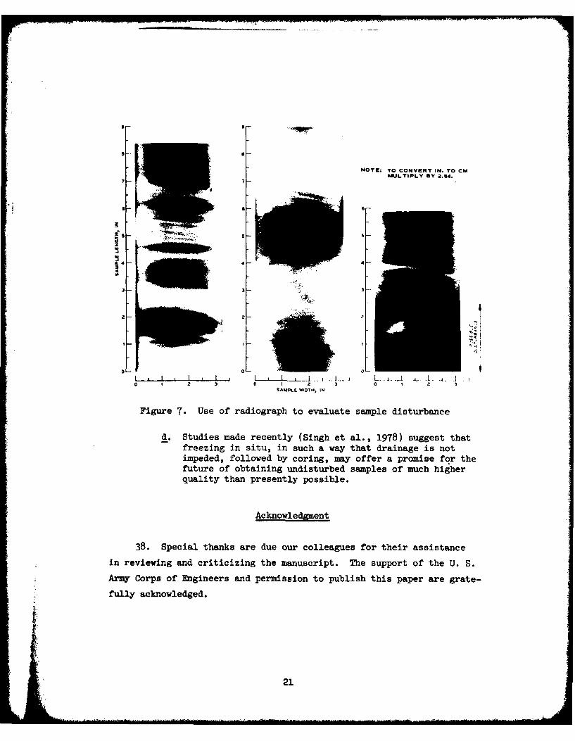
sample variations, layering, and disturbance. Figure 7 shows radio-
graphs of both high-quality and low-quality undisturbed samples. Notice
that in the high-quality samples, the bedding planes can be seen all the
way to the sample edge. In the low-quality sample, these planes are
contorted, indicating possible disturbance.
Conclusions and Recommendations
37. Based on the experience summarized herein, the following con-
clusions and recommendations can be made:
a. High-quality, undisturbed samples of many sands can be ob-tained using a fixed-piston sampler and drilling mud, ifproper care and attention to the details of the sampling,handling, and transportation process are exercised. Thissampling process yields very good samples of medium densesands, but tends to densify loose sands and loosen densesands. This disturbance appears to be a function of rela-tive density, overburden pressure, and position in the
4 sample tube. It may cause the sample density to be inerror as much as 64 kg/m3 in extreme cases.
19
• .. .. ..., .. ....- ..
4-L-
3.00 1.50RADIOGRAPH FILM DE NSITY-f-. CORE
HUXTABLE-SANDNX CORE IN STEEL SLEEVE
Figure 6. Use of radiograph film density to indicate variation
of soil density in sample tube
b. The use of radiographs is an adequate and reliable nondes-structive method for determining the layering of the sam-ple and the degree of disturbance inside the sample tube.If facilities are available, this method of examining thesample should be routinely used.
c. Where gravels are encountered, the only proven effectiveSmeans of recovering undisturbed samples is by hand-carving
Figure 7. Use of radiograph to evaluate sample disturbance
d. Studies made recently (Singh et al., 1978) suggest thatfreezing in situ, in such a way that drainage is notimpeded, followed by coring, may offer a promise for thefuture of obtaining undisturbed samples of much higherquality than presently possible.
Acknowledgment
38. Special thanks are due our colleagues for their assistance
in reviewing and criticizing the manuscript. The support of the U. S.
Army Corps of Engineers and permission to publish this paper are grate-
fully acknowledged.
21
References
1. American Society for Testing and Materials (1974), Annual Book ofASTM Standards Part 19, Philadelphia, Pa., pp. 192-194, 206-207,224-229, 261-263, and 317-320.
2. American Society of Civil Engineers (1978), Soil Sampling and ItsImportance to Dynamic Laboratory Testing, Preprint 3440, ASCENational Convention, Chicago, Ill.
3. Arman, A. R. A., and McManis, K. L. (1976), "Effects of Storage andExtrusion on Sample Properties," Soil Specimen Preparation forLaboratory Testing, STP 599, American Society for Testing andMaterials, Philadelphia, Pa., pp. 66-87.
4. Barton, C. M. (1974), "Borehole Sampling of Saturated UncementedSands and Gravels," Groundwater, Vol 12, No. 3, pp. 170-181.
5. Cooper, S. S. (1976), "Laboratory Investigation of UndisturbedSampling of Cohesionless Material Below the Water Table," ResearchReport S-76-1, U. S. Army Engineer Waterways Experiment Station,Vicksburg, Miss.
6. Davis, H. E. (1969), "Suggested Method for Soil Investigation andSampling by Hollow-Stem Auger Borings," Special Procedures forTesting Soil and Rock for Engineering Purposes, STP 479, AmericanSociety for Testing and Materials, Philadelphia, Pa., pp. 69-70.
7. Geotechnical Engineers, Inc. (1976), Report on Test Pit Investiga-tion and Laboratory Testing, Preliminary Safety Analysis Report,Pilgrim Station, Appendix 2A.2-4, Pilgrim Nuclear Station No. 600,
Unit 2, Boston Edison Co., Submitted to Bechtel Corporation.
8. Hvorslev, M. J. (1949), Subsurface Exploration and Sampling of Soilsfor Civil Engineering Purposes" U. S. Army Engineer WaterwaysExperiment Station, Vicksburg, Miss. (available from EngineeringFoundation, New York).
9. Karol, R. H. (1971), "Use of Chemical Grouts to Sample Sands,"Sampling of Soil and Rock, STP 483, American Society for Testingand Materials, Philadelphia, Pa., pp. 51-59.
10. KJellman, W., Kallstenius, T., and Wager, 0. (1950), Soil Samplerwith Metal Foils, Proceedings No. 1, Royal Swedish GeotechnicalInstitute, Stockholm.
11. Krinitzsky, E. L. (1970), Radiography in Earth Sciences and Soil
Mechanics. Plenum Publishing Company, New York/London.
12. Marcuson, W. F. III (1976), "Earthquake Analysis of the W. G.Huxtable Pumping Plant Site," Miscellaneous Paper S-76-8, U. S.Army Engineer Waterways Experiment Station, Vicksburg, Miss.
13. Marcuson, W. F. III (1978), "Determination of In Situ Density ofSands," Dynamic Geotechnical Testing, STP 654, American Societyfor Testing and Materials, Philadelphia, Pa., pp. 318-340.
22
14. Marcuson, W. F. III, Cooper, S. S., and Bieganousky, W. A. (1977),"Laboratory Sampling Study Conducted on Fine Sands," 9th Interna-tional Conference on Soil Mechanics and Foundation Engineering,Proceedings of Specialty Session No. 2, Tokyo, pp. 15-22.
15. Marcuson, W. F. III and Gilbert, P. A. (1972), "Earthquake Lique-faction Potential at Patoka Dam, Indiana," Miscellaneous PaperS-72-74, U. S. Army Engineer Waterways Experiment Station,Vicksburg, Miss.
16. Marcuson, W. F. III and Krinitzsky, E. L. (1976), "Dynamic Analysisof Fort Peck Dam.," Technical Report S-76-1, U. S. Army EngineerWaterways Experiment Station, Vicksburg, Miss.
17. McCoy, F. W., Jr. (1972), "An Analysis of Piston Coring ThroughCorehead Camera Photography," Underwater Soil Sampling, Testing.and Construction Control. STP 501, American Society for Testingand Materials, Philadelphia, Pa., pp. 90-105.
18. Mori, K., Seed, H. B., and Chan, C. K. (1978), "Influence of SampleDisturbance on Sand Response to Cyclic Loading," Journal of theGeotechnical Engineering Division, American Society of Civil Engi-neers, Vol 104, No. GT3, pp. 323-339.
19. Noorany, I. (1972), "Underwater Soil Sampling and Testing-A State-of-the-Art Review," Underwater Soil Sampling, Testing, and Construc-tion Control, STP 501, American Society for Testing and Materials,Philadelphia, Pa., pp. 3-41.
20. Osterberg, J. 0. (1952), "New Piston-Type Soil Sampler," Engineer-ing News-Record, Vol 148, pp. 77-78.
21. Osterberg, J. 0. (1973), "An Improved Hydraulic Piston Sampler,"Proceedings of the 8th International Conference on Soil Mechanicsand Foundation Engineering, Moscow, USSR, Vol 1.2, pp. 317-321.
22. Osterberg, J. 0., and Varaksin, S. (1973), "Determination of Rela-tive Density of Sand Below Groundwater Table," Evaluation of Rela-tive Density and Its Role in Geotechnical Projects InvolvingCohesionless Soils. STP 523, American Society for Testing andMaterials, Philadelphia, Pa., pp. 364-376.
23. Peck, R. B., Hanson, W. E., and Thornburn, T. H. (1974), FoundationEngineering. 2nd Ed., John Wiley & Sons, Inc., New York.
I 24. Singh, S., Chan, C. K., and Seed, H. B. (1978), "UndisturbedSampling and Cyclic Load Testing of Sands," Contract Report to theU. S. Army Engineer Waterways Experiment Station, Vicksburg, Miss.(unpublished).
25. Task Committee for Foundation Design Manual (1972), "SubsurfaceInvestigation for Design and Construction of Foundations of Build-ings," Journal of Soil Mechanics and Foundations Division, AmericanSociety of Civil Engineers, Vol 98, No. SM5, pp. 481-490; Vol 98,No. SM6, pp. 557-558; Vol 98, No. SM7, pp. 749-764; and Vol 98,No. SM8, pp. 771-785.
23
26. Terzaghi, K. and Peck, R. B. (1968), Soil Mechanics in EngineeringPractice, 2nd Ed., John Wiley & Sons, Inc., New York.
27. Tirey, G. B. (1972), "Recent Trends in Underwater Soil SamplingMethods," Underwater Soil Sampling, Testing, and ConstructionControl. STP 501, American Society for Testing and Materials,Philadelphia, Pa., pp. 42-54.
28. U. S. Army (1952), "Density Changes of Sand Caused by Sampling andTesting," Potamology Investigations Report No. 12-1, U. S. ArmyEngineer Waterways Experiment Station, Vicksburg, Miss.
29. U. S. Army (1972), Engineer Manual EM 1110-2-1907, Soil Sampling,Department of the Army, Office of the Chief of Engineers.
30. U. S. Army (1962), "Rotary Cone Penetrometer Investigations," Pota-mology Investigations Report 18-1, U. S. Army Engineer WaterwaysExperiment Station, Vicksburg, Miss.
31. U. S. Bureau of Reclamation (1960), Earth Manual, 1st Ed., Depart-ment of the Interior, Bureau of Reclamation (USBR).
32. Walberg, F. C. (1978), "Freezing and Cyclic Triaxial Behavior ofSands," Technical Note, Journal of the Geotechnical EngineeringDivision, American Society of Civil Engineers, Vol 104, No. GT5,pp. 667-671.
33. Windisch, S. J. and Soulie, M. (1970), "Technique for Study ofGranular Materials," Journal of Soil Mechanics and FoundationsDivision, American Society of Civil Engineers, Vol 98, No. SM4,pp. 1013-1026.
34. Yoshimi, Y., Hatanaka, M., and Oh-Oka, H. (1978), "Undisturbed
Sampling of Saturated Sands by Freezing," Soils and Foundations,The Japanese Society of Soil Mechanids and Foundation Engineering,Vol 18, No. 3, pp. 59-73.
24
Mr
Table 1
Method Procedure Applicability Limitations and Pitfalls
Pits, trenches, Excavation made by hand, Visual observation, photo- Depth of unprotected excavationsshafts, tunnels large auger. or diging graphy disturbed and un- is limited by groundwater or
machinery (Nvorslev. disturbed sampling, in situ safety considerations1949, pp. 66-71) testing of soil and rock
Auger boring Boring advanced by hand Recovery of remolded samples Will not penetrate boulders or hardauger or power auger location of groundwater rock(Hvorslee, 1949, table. Access for undis-
pp. 61-64) turbed sampling of cohesivesoils
Hollow auger Boring advanced by Access for undisturbed or Should not be used with plug inmans of continuous- representative sampling granular soils. Not suitable forflight helix auger with through hollow stim with undisturbed sampling in loosehollow center stem thin-wall tube sampler, sand or silt (Peck et sl., 197.,(Davis, 1969) core barrel, or split- pp. 105-106)
sp0on samplerWash boring Boring advanced by chop- Cleaning out and advancing Suitable for use with sampling
ping with light bit and hole in soil between saw- operations in soil only if doneby Jetting with upward- ple intervals with low water velocities anddeflected Jet (Hvorslev, with upward-deflected Jet1949. pp. 52-54)
Rotary drilling Boring advanced by Cleaning out sad advancing Drilling mud should be used inrotating drilling bit hole in soil or rock be- granular soils. Bottom-dischargewith cuttings removed tween eample intervals bits are not suitable for useby circulating drilling with undisturbed sampling influid (Hvorslev, 1949, soils, unless combined with pro-pp. 57-61) truding core barrel, as in Deni-
sn sampler
Percussion Boring advanced by air- Detection of voids and zones Limited to --- ll-dimeter holedrilling operated impact hmaier Of weakness in rock by
changes in drill rate orzsi stance. Access for insitu testing or lowging
Cable drilling Boring advanced by Advancing hole in soil or Causes severe disturbance in soils;repeated dropping of rock. Access for sam- not suitable for use with undis-heavy bit and removal plnug, in situ testing, turbed sampling methodsof cuttings by bailing or logging in rock. Pene-(ibid.) tration of bard layers,
gravel. or boulders inauger borings
Continuous Boring advanced by re- Recovery of representative Effects of advance and withdravalsampling or peated pushing of samples of cohesive soils, of esampler result in disturbeddisplacement simpler, or closed undieturbed samples in some sections at top and bottom ofboring sampler is pushed to cohesive soils sample. In some soils, entire
desired depth and sample soy be disturbed. Notjamsple is taken (ibid.) suitable for use in cohesionless
soils
4
Table 2
Methods of Undisturbed Sampling of CohesionleS. Soil
Proo.dum - Asolicabilitv Limitation. aud Pitfalls
Rand-cut block or Sample Is cut by band from soil @x- Highest quality undisturbed samples In Requires accessible excavation sod dewater-cylindrical posed in escavation (rasM. 1960, cohsive soile, cohesionleas soils, lug If below water table. Extreme care Issampler pp. 3"6-349; Terzashi sod Peck, sod soft rock required is sampling cohesionle.2 soils.
1968, pp. 312-314.) The state of st~ress is changed by theexcavation
GR1 sampler Sample is hsd-trimd Into cylin- Undisturbed samples in cobesiouleas Requires accessible excavation and delcater-drical sample, tube that is sup- moils, of quality comp.arable to baud- lug If bolos water table. ?he state ofported sod guided by a tripod cut block sample stress is changed by the maceationholder (Osoteccl engineers.Inc..* 19T6; Sorcusos 1978)
This-walled tube This-walled tube is pushed Iuto soil Undisturbed or representative samples Not suitable for se is extremely hard soils,somplre at bottom of boping. (April in cohesive soils sod cohesionless gravel, or stony soils. Strict attention
01587-67, U. S. Army, 1972. Ch. 4) soils that are free of gravel to details of equimet a&d procedure isParticles, required to obtain undisturbed samples of
good quality (ibid., Ch. 3 & 1.* ivorslev.19. pp. 83.139)
iWor Types of This-Walled Tube Samplers Are Listed Below
Fixedi-pistam This-walled tube is pushed Into Undisturbed samples is cohesive soils@. Some types do not have positive preventimsaplr soil, with fixed piston Is con- silts. sod aeede. above or bolos the of piston moement
tact with top of ample during enter tableposh. (U. S. Amy, 1972. Cb. 3.Nwrslev. 191. pp. 128-130.U. 1960. pp. 3k.9-379)
Hydraulic piston This-walled tube Ie pushed into soil Undisturbed samples In cobroive soils. Not possible to limait the length of push ors~erby hydraulic pressure. Pixed silts. ansd aeede, above or below to determine amount of partial sempler
(Osterberg) piston is contact With top of the water table pe-vtration during Push. Earlier versionsomle, derng push. (Osterberg. duor .'.t hey vacuum beaeker is pisto=1952 sod 1973; Ul. S. Army. 1972.Ch. 3)
Stationary piston This-walled tube is pushed Into Undisturbed eamples in stiff cohesive Piston does sot provide positive control ofsampler soll. Piston at t-p of sample soils; representative samples in soft specific recovery ratio
Is free to moye upward but is to Sedium cohesive soils, silts. sodrestrained from downward movement som sandsby a friction lock
Pree-pletus This-walled tube is pushed Into Undisturbed saples In stiff cohesive Not suitable -'or sapling In cohesioniesssomlor 0ail. Piston Feet& on tap at sil saile. nopmewesimr samples In sajls. Prot pljioc provides no control
emple during push (ibid.. C h. 3; soft to madius cohesive soIls sad of specific recovery ratioNvorolew. 1949. p. 131) silts
Opan-dnive Thin-walled. open tube Is pushed Undisturbed samples is stiff cohesive Not buitable for sampling is coheslonlessewler into soil (ibid..* p. 133; USER. soils. Representative samples Is soils. So control of specific recovery
1960. pp. 361-367) soft to medi e cohesive soils sod ratiosilts
Pitcher sampler Thin-walled tube Is pushed into soil Undisturbed Samples in hard, brittle. Frequently Ineffective In cohesionlessby sping above sampler while cohesive sois sod sends with soilscuter sore bit ren hole. conntation. Representative samplesCuttilga remoead by circulating Is soft to sodiumn cohesive soils anddrilling fild (Ternaghi ad Peck, silts. Disturbed saples soy be oh-1968. pp. 310-312) tamd is cabeoless- materials with
variable successDsenion sempler Mole Is advanced sad reamed by core Undisturbed samples in stiff to hard Not suitable for undisturbcd sampling in
drill while sample Is retained in cohesive soil, sands with cementa- loose cohesionless soils or soft robe-nonrotating inn er*r barrel with tin. and soft rocks. Disturbed sic. soIlscoreatcher. Cuttings rosoved by stpe soy be obtaine" In cohesion-circulating drilling fluid (ibid.,* less materials with variable Becomespp. 312-313; U80S, 1960,pp. 355-361)
Sumraible Core tube Is drives into soil by Continuous represtative amples is Because of high area, ratio aid effects ofvibratory vibrator. (Tirey, 197) unconsolidated sane sediments vibration. m~l*. are disturbed(vibracore)sampler
Underwater Core tube attached to drop meight is Representative samples is unconsolim Sampls way be seriously disturbedp itn corer driven Into soil by gravity after dated arise sediments (*cCoy. 1972)
a controlled height of free fal.Cable-supported piston remains Iscontact with mall surface duringdrive (Soormay 19T.2)
Gravity corer Open-core tube attached to drop Representative saples at shallow depth So control of specific recovery ratio.weight is driven into soil by is unconsolidated marise sediments Sampies are disturbed= avity after free fall
mSo ran. 197)
In accordance with letter from DAEN-RDC, DAMEN-AST dated22 July 1977, Subject: Facsimile Catalog Cards forLaboratory Technical Publications, a facsimile catalogcard in Library of Congress MARC format is reproducedbelow.
Marcuson, William FrederickState of the art of undisturbed sampling of cohesionless
soils / by William F. Marcuson III, Arley G. Franklin.Vicksburg, Miss. : U. S. Waterways Experiment StationSpringfield, Va. : available from National Technical Informa-tion Service, 1979.
24, [2] p. : ill. ; 27 cm. (Miscellaneous paper - U. S.Army Engineer Waterways Experiment Station ; GL-79-16)
Prepared for Office, Chief of Engineers, U. S. Army,Washington, D. C., under CWIS Work Units 31145 and 31619.
References: p. 22-24.
1. Cohesionless soils. 2. Soil sampling. 3. State-of-the-art studies. 4. Undisturbed sampling. 1. Franklin, Arley G.,joint author. II. United States. Army. Corps of Engineers.I1. Series: United States. Waterways Experiment Station,Vicksburg, Miss. Miscellaneous paper ; GL-79-16.TA7.W34m no.GL-79-16