SUMMARY OF MODIFICATIONS TO THE MOUNT WERNER WATER 2014 STANDARD SPECIFICATIONS FOR WATER AND WASTEWATER UTILITIES Section 30: Water Distribution Piping and Appurtenances and Detail 19: • Revised Air Release Valve. Specification to be determined. Section 30. Service line Appurtenances with diameters 2-inches or less: • Revised all brass fittings to meet current CDPHE regulations; No Lead/Low Lead; (NL) or (N). Section 35: Pressure Reducing Valve and Vault and Detail 22: • Revised various components.
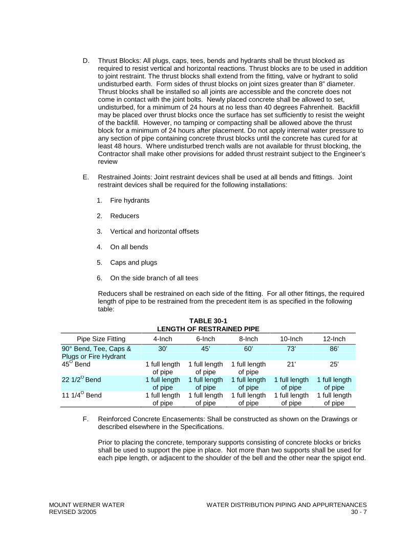
Transcript
SUMMARY OF MODIFICATIONS TO THE MOUNT WERNER WATER 2014 STANDARD SPECIFICATIONS
FOR WATER AND WASTEWATER UTILITIES Section 30: Water Distribution Piping and Appurtenances and Detail 19:
• Revised Air Release Valve. Specification to be determined. Section 30. Service line Appurtenances with diameters 2-inches or less:
• Revised all brass fittings to meet current CDPHE regulations; No Lead/Low Lead; (NL) or (N). Section 35: Pressure Reducing Valve and Vault and Detail 22:
• Revised various components.
STANDARD SPECIFICATIONS FOR
WATER AND WASTEWATER UTILITIES
EFFECTIVE January 2014
3310 Clear Water Trail P.O. Box 880339
Steamboat Springs, CO 80488 (970) 879-2424
FAX (970) 879-8169
MOUNT WERNER WATER STANDARD SPECIFICATIONS
TABLE OF CONTENTS
Section Number Subject
1 Procedure for Water and Wastewater Extensions 2 Applicable Standards 4 Engineering Services 6 Staking, Quantities and Drawings of Record 8 Submittals and Substitutions 12 Materials Equipment and Workmanship 14 Traffic regulation 15 Water Pollution Control 16 Dust Control 20 Clean-up 22 Re-vegetation 24 Trenching Bedding and Backfill 26 Pavement Removal and Replacement 30 Water Distribution Piping and Appurtenances 35 Pressure Reducing Valve and Vault 40 Wastewater Collection Piping and Appurtenances 42 Manholes 44 Water and Wastewater Line Crossings Details
Sheet 1 Trench Cross-Section and Pipe Embedment Sheet 2 Service Line Sheet 3 Joint Restraint Sheet 4 Thrust Block Sheet 5 Vertical Thrust Block Detail Sheet 6 Fire Hydrant Sheet 7 Fire Hydrant Bench Sheet 8 Standard Manhole Sheet 9 Drop Manhole Sheet 10 Typical Duplex Service Line Location Detail Sheet 11 Irrigation Service Detail Sheet 12 Sewer Cleanout Detail Sheet 13 Sewer Service Lateral Connection Detail Sheet 14 2” and Larger Meter Installation Detail Sheet 15 ¾” – 1½” Meter – Vertical Set Installation Detail Sheet 16 ¾” – 1½” Meter – Horizontal Set Installation Detail Sheet 17 Tracer Wire Installation Detail Sheet 18 Blow-off Hydrant Detail Sheet 19 Air Release Assembly Detail Sheet 20 Water and Sewer Crossings (sheet 1 of 2) Sheet 21 Water and Sewer Crossings (sheet 2 0f 2) Sheet 22 Standard Pressure Reducing Valve / Vault (PRV) Detail
Appendices
Appendix A Request for Water and Sewer Services and Waiver and Acknowledgement Form Appendix B Construction Plan and Specification Requirements for Water and Sewer
Main Extensions Addendum 1 Cold Weather Specifications
SECTION 1: PROCEDURE FOR WATER AND WASTEWATER EXTENSIONS The extension of water and wastewater mains generally proceed as follows, however each project is evaluated on a case-by-case basis and additional requirements may be required of individual projects. 1.0 Development Review
The review of proposed water and wastewater extensions is performed in conjunction with the City of Steamboat Springs planning process. A preliminary engineered utility plan is required and will be reviewed in context to the other submitted plans such as site, grading and landscaping plans. Mount Werner Water will recommend approval of the development permit after all major issues are worked out.
2.0 Approval of Construction Drawings and Pre-construction Meeting
Engineered water and sewer utility plans are required for any water or sewer main line extension, whether public or private. The construction plans and specifications shall be prepared by an engineer registered in the state of Colorado. To allow adequate time for review and revisions, plans should be submitted at least three weeks prior to the start of any construction. Approval of Request for Water and Sewer Services and Waiver and Acknowledgement The owner of the property shall obtain a copy of the “Request for Water and Sewer Services and Waiver and Acknowledgement” form from Mount Werner Water. The form is to be signed and recorded against the property with the Routt County Clerk and Recorder. A copy of the recorded document is to be provided to Mount Werner Water. The recorded document must be presented to Mount Werner Water prior to approval of the construction drawings. See Appendix A for a copy of this agreement. Specifications The project specifications shall be the Mount Werner Water Standard Specifications for Water and Wastewater Utilities. Additional specifications and special conditions should be used to cover other areas of project construction, such as grading and road construction. Drawings The drawing set must include, as a minimum; a site plan, grading plan, water and wastewater plan, wastewater main profile sheet, detail sheet, a dry utility plan with the wet utilities shown, and a landscape plan with wet utilities and easements shown. In addition, a profile must be provided for all existing mains which are impacted by any grading to be done as part of the project. See appendix B for a checklist of the construction plan requirements. For initial review, one set of plans and specifications should be submitted. These will be red lined for revision and returned to the engineer to make the needed revisions. Two or more final sets with all revisions should be submitted along with the original red lined drawings. Pre-Construction Meeting Prior to commencing construction, a pre-construction meeting is required to be held between the project engineer, the contractor and a representative from Mount Werner Water. At the pre-construction meeting, the approved construction plans will be delivered to the engineer and contractor. In addition the following items will be reviewed and discussed: • Review the staking and alignment • Inspect the materials and discuss any substitutions • Review the inspection requirements (both by the project engineer and Mount Werner Water) • Review the test methodology • Insure the contractor has a current set of Mount Werner Water specifications • Any other topics relevant to the project dealing with water or sewer.
MOUNT WERNER WATER PROCEDURE FOR WATER & WASTEWATER EXTENSIONS REVISED 3/2005
• The Engineer shall generate meeting minutes and distribute to all attendees within 1-week of the Pre-Construction meeting.
3.0 Construction, Testing and Quality Control
The Engineer is responsible for coordination and documentation of all required engineering inspections as outlined in Section 4, “Engineering Services”, and for witnessing and documenting all inspection items as identified within the “Standard Inspection Forms”.
The project engineer or a representative from Mount Werner Water is required to inspect every live tap and every thrust block prior to backfilling.
3.1 Changed Conditions or Deficient Work
Changed Conditions or Deficient Work from the approved plans and specifications shall be documented by the Engineer and presented with revised corrective actions to Mount Werner Water for review and final approval. Various options may be evident in the resolution of a Changed Condition or Deficient Work item. All requests shall be made in writing to Mount Werner Water. Plans by the Contractor to resolve a Changed Condition or Deficient Installation issue shall be reviewed, approved and initialed by the Engineer, red-lined by the Engineer, or redrafted by the Engineer prior to submittal to Mount Werner Water. All such requests by the Contractor shall be incorporated by the Engineer into a Corrective Action Plan. All Corrective Action Plans shall ultimately bring the deficient work into conformance with Mount Werner Water specifications and/or the approved project plans and specifications, whichever is in the best interests of the District.
During the course of the work, the Engineer shall immediately contact Mount Werner Water, if the Engineer, or Others, witness work being completed by the contractor, or others, not conforming to Mount Werner Water specifications.
4.0 Preliminary Acceptance
Upon substantial completion of the work, the engineer must submit a request in writing for a preliminary acceptance inspection by Mount Werner Water. The Site needs to be within 0.20 feet of design subgrade and at least the first lift of asphalt needs to be in place. All manholes, valve boxes and appurtenances need to be to grade and fully accessible.. The request is to be accompanied by test results, all field notes, and field staking of utility easements. If the joint inspection with the Engineer, Contractor and Mount Werner Water reveals any deficiencies, a punch list shall be generated. Once items on the punch list have been corrected a re-inspection should be requested. This shall be repeated until no items remain on the punch list. In addition, the as-built documents are to be reviewed and approved by Mount Werner Water and all easements are to be recorded. Once all punch list items have been completed, the as-built documents accepted, and the easements recorded, the project will be granted preliminary acceptance which allows for the extension of service lines to buildings and service provided. The Warranty Period, including special Warranties for Cold Weather Specifications, shall officially begin from the date of the Letter of Preliminary Acceptance written by Mount Werner Water. Upon written request, Mount Werner Water may allow and permit temporary water and sanitary sewer services to the improvements during the period of construction of the improvements, provided that the new mains have passed pressure and biological testing. See the “Request for Water and Sewer Services and Waiver and Acknowledgement” for further details.
MOUNT WERNER WATER PROCEDURE FOR WATER & WASTEWATER EXTENSIONS REVISED 3/2005
Inspections will not be made between November 1 and April 30 when weather would prohibit a thorough inspection. Until final acceptance is granted, the mains shall be under warranty and any maintenance and repair work is the responsibility of the developer.
5.0 Final Acceptance
After one year from preliminary acceptance, a request for final acceptance should be made. Any deficiencies found during this inspection shall be corrected prior to granting final acceptance of the mains.
6.0 Definition of Engineer
Any and all reference to the word “engineer” shall mean: The design engineer who has stamped and certified the approved construction documents.
MOUNT WERNER WATER PROCEDURE FOR WATER & WASTEWATER EXTENSIONS REVISED 3/2005
SECTION 2 APPLICABLE STANDARDS
1.0 GENERAL
1.1 DESCRIPTION
A. Work included: Throughout the Contract Documents, reference is made to codes and standards which establish qualities and types of workmanship and materials, and which establish methods for testing and reporting on pertinent characteristics.
Where materials or workmanship are required by these Contract Documents to meet or
exceed the specifically named code or standard, it is the Contractor’s responsibility to provide materials and workmanship which meet or exceed the specifically named code or standard.
It is also the Contractor’s responsibility, when so required by the Contract Documents or
by written request from the Engineer, to deliver to the Engineer all required proof that the materials or workmanship, or both, meet or exceed the requirements of the specifically named code or standard. Such proof shall be in the form requested in writing by the Engineer, and generally will be required to be copies of a certified report of tests conducted by a testing agency approved for that purpose by the Engineer.
B. Related work described elsewhere: Specific naming of codes or standards occurs on the
drawings and in other sections of these Specifications.
1.2 QUALITY ASSURANCE
A. Familiarity with pertinent codes and standards: In procuring all items used in this work, it is the Contractor’s responsibility to verify the detailed requirements of the specifically named codes and standards and to verify that the items procured for use in this work meet or exceed the specified requirements.
B. Rejection of non-complying items; The Engineer reserves the right to reject items
incorporated into the work which fail to meet the specified minimum requirements. The Engineer further reserves the right, and without prejudice to other recourse the Engineer may take, to accept non-specified items subject to review and approval by Mount Werner Water. Under Mount Werner Water Contracts, an adjustment in the Contract Amount may be applicable.
C. Applicable standards listed in these Specifications include, but are not necessarily limited
to, standards promulgated by the following agencies and organizations:
1. AASHTO - America Association of State Highway and Transportation Officials, 341 National Press Building, Washington, DC. 20004.
2. ACI - American Concrete Institute, P.O. Box 19150, Redford Station, Detroit, MI 48219.
3. AISC - American Institute of Steel Construction, Inc., 1221 Avenue of the Americas, New York, NY 10020.
4. ANSI - American National Standards Institute (successor to USASI and ASA) 1430 Broadway, New York, NY 10018.
5. ASTM - American Society for Testing and Materials, 1916 Race Street, Philadelphia, PA 19103.
MOUNT WERNER WATER APPLICABLE STANDARDS REVISED 3/2005 2 - 1
7. AWWA - American Water Works Association, Inc., 6666 West Quincy Ave., Denver, CO 80235
8. CRSI - Concrete Reinforcing Steel Institute, 228 North Lasalle Street, Chicago, IL 60610
9. CS - Commercial Standard of NBS, U.S. Department of Commerce, Government Printing Office, Washington, DC 20402.
10. FGMA - Flat Glass Marketing Association, 3310 Harrison, Topeka, KS 66611 11. NAAMM - The National Association of Architectural Metal Manufacturers, 1033
South Boulevard, Oak Park, IL 60302. 12. NEC - National Electrical Code (see NFPA). 13. NEMA - National Electrical Manufacturers Association, 155 East 44th Street, New
York, NY 10017. 14. NFPA - National Fire Protection Association, 470 Atlantic Avenue, Boston, MA
02210 15. SDI - Steel Deck Institute, 135 Addison Avenue, Elmherst, IL 60125. 16. SSPC - Steel Structures Painting Council, 4400 5th Avenue, Pittsburgh PA 15213. 17. TCA - Tile Council of America, Inc., P.O. Box 326, Princeton, NJ 08540. 18. Underwriter’s Laboratories, Inc., 207 East Ohio Street, Chicago, IL 60611. 19. Fed Specs. and Fed Standards, Specifications Sales (3 FRI), Building 197,
Washington Navy Yard, General Services Administration, Washington, DC 20407. 20. MIL-SPECS, Military Specifications, Superintendent of Documents, U.S.
Government Printing Office, Washington, DC 20402. 21. UBC - Uniform Building Code, International Conference of Building Officials, 5360
South Workman Mill Road, Whittier, CA 90601. 22. UPC - Uniform Plumbing Code, International Association of Plumbing and
Mechanical Officials, 2001 Walnut Drive South, Walnut, CA 91789-2825. 2.0 PRODUCTS No products this Section 3.0 EXECUTION
The Contractor is responsible for being familiar with all named or implied codes. The latest revision or edition of codes or standards shall be used.
4.0 MEASUREMENT AND PAYMENT
No separate measurement for payment will be made for the work under this Section. Its cost shall be considered incidental to the project.
MOUNT WERNER WATER APPLICABLE STANDARDS REVISED 3/2005 2 - 2
SECTION 4 ENGINEERING SERVICES
1.0 GENERAL
1.1 DESCRIPTION
Minimum level of construction engineering services to be provided by a project owner for development work requiring water and wastewater facilities served by Mount Werner Water. Note: the construction engineering work items listed are intended to be the minimum guidelines to which the owner shall comply. The actual level of construction engineering shall be that required to assure conformance with all detailed requirements of the approved plans and specifications. The minimum level of engineering services to be provided for construction projects shall be as follows:
I. QUALIFICATIONS OF PROJECT OBSERVATION PERSONNEL
A. The individual(s) completing construction observation for water and wastewater shall
be a professional engineer registered in the State of Colorado or a properly trained engineering technician who is under the direct supervision of a professional engineer. Such person shall not be employed by or affiliated with the developer or any affiliate of the developer. The on-site personnel shall be experienced in construction observation of wastewater collection and water distribution pipelines and appurtenances.
II. WATER AND WASTEWATER MAIN INSTALLATION
A. Limits of right of way and easements shall be established prior to staking of mains. B. Stake center-line of main and location of all appurtenances.
1. Manhole invert elevation to be staked with offset hub elevations with cuts and
stationing. 2. Wastewater mains shall be staked for grade.
C. Observation - pipeline installation
1. Document all pipeline materials meet approved specifications. 2. Observe trench preparation and placement of bedding and shading materials. 3. Observe all mechanical joint fittings and thrust blocks prior to backfill. GPS
point data shall be obtained at every bend and change in direction for watermains.
4. Engineer shall document as-constructed conditions prior to backfill. 5. Pipelines to receive construction observation as required to assure compliance
with specifications.
MOUNT WERNER WATER ENGINEERING SERVICES REVISED 3/2005 4 - 1
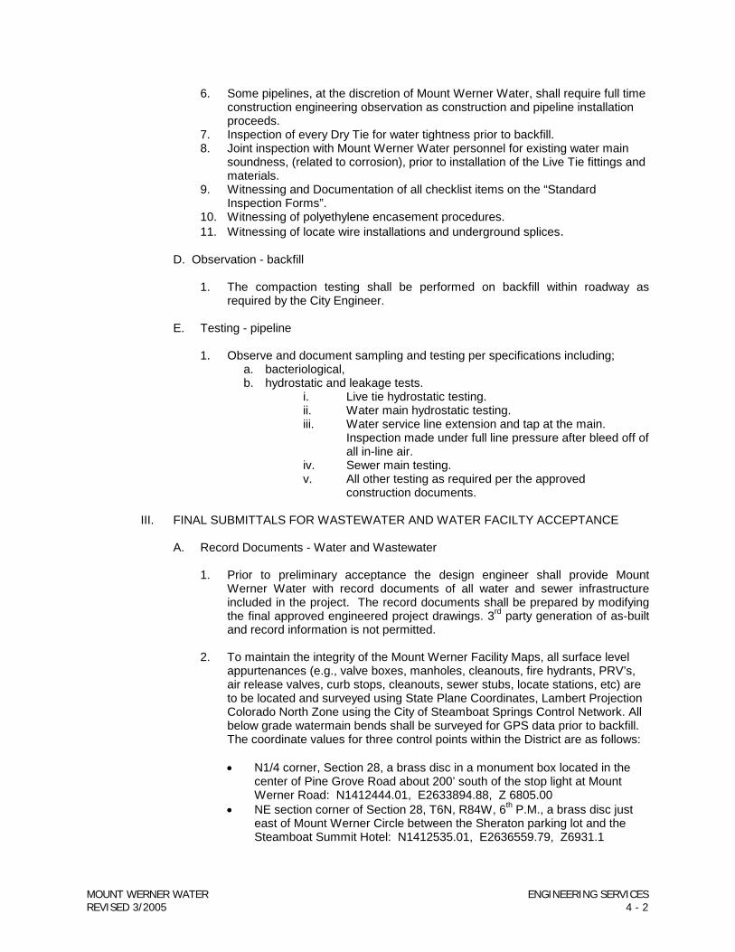
6. Some pipelines, at the discretion of Mount Werner Water, shall require full time construction engineering observation as construction and pipeline installation proceeds.
7. Inspection of every Dry Tie for water tightness prior to backfill. 8. Joint inspection with Mount Werner Water personnel for existing water main
soundness, (related to corrosion), prior to installation of the Live Tie fittings and materials.
9. Witnessing and Documentation of all checklist items on the “Standard Inspection Forms”.
10. Witnessing of polyethylene encasement procedures. 11. Witnessing of locate wire installations and underground splices.
D. Observation - backfill
1. The compaction testing shall be performed on backfill within roadway as required by the City Engineer.
E. Testing - pipeline
1. Observe and document sampling and testing per specifications including;
a. bacteriological, b. hydrostatic and leakage tests.
i. Live tie hydrostatic testing. ii. Water main hydrostatic testing. iii. Water service line extension and tap at the main.
Inspection made under full line pressure after bleed off of all in-line air.
iv. Sewer main testing. v. All other testing as required per the approved
construction documents.
III. FINAL SUBMITTALS FOR WASTEWATER AND WATER FACILTY ACCEPTANCE
A. Record Documents - Water and Wastewater
1. Prior to preliminary acceptance the design engineer shall provide Mount Werner Water with record documents of all water and sewer infrastructure included in the project. The record documents shall be prepared by modifying the final approved engineered project drawings. 3rd party generation of as-built and record information is not permitted.
2. To maintain the integrity of the Mount Werner Facility Maps, all surface level
appurtenances (e.g., valve boxes, manholes, cleanouts, fire hydrants, PRV’s, air release valves, curb stops, cleanouts, sewer stubs, locate stations, etc) are to be located and surveyed using State Plane Coordinates, Lambert Projection Colorado North Zone using the City of Steamboat Springs Control Network. All below grade watermain bends shall be surveyed for GPS data prior to backfill. The coordinate values for three control points within the District are as follows:
• N1/4 corner, Section 28, a brass disc in a monument box located in the
center of Pine Grove Road about 200’ south of the stop light at Mount Werner Road: N1412444.01, E2633894.88, Z 6805.00
• NE section corner of Section 28, T6N, R84W, 6th P.M., a brass disc just east of Mount Werner Circle between the Sheraton parking lot and the Steamboat Summit Hotel: N1412535.01, E2636559.79, Z6931.1
MOUNT WERNER WATER ENGINEERING SERVICES REVISED 3/2005 4 - 2
• E1/4 witness corner for section 28, a brass disc located in the sidewalk north of Walton Creek Road and near the SW corner of the Discovery Learning Center: N1409932.99, E2636480.05, Z6827.21.
The N, E, and Z coordinates are to be included on the record documents for these appurtenances.
3. After initial review of the record documents, Mount Werner Water will either
approve or return for revisions.
4. After the blue line review set of record documents have been approved by Mount Werner Water, provide the following documentation:
a. One Full Size set of Reproducible Mylars of all appropriate project sheets
b. One set of 11 x 17 Photo copies of the project drawings. c. 2 –sets of 3-point tie sheets on 8 ½ x 11 sheets locating all
d. Digital CADD drawings. e. PDF Copy of the Final Record Drawings. All sheets in one PDF file
Printable in 24” x 36” format. f. PDF Copy of all 3-point Tie Sheets. All sheets in one PDF file. g. Water and Sewer Project Inspection Photos; dated and with subject
captions. h. One copy of Engineer’s field inspection logs on Standard Forms i. One certified copy of the Engineer’s Water and Sewer testing summary. j. One signed and stamped Letter by the Engineer of Record indicating
that all water and sewer work has been completed to Mount Werner Water specifications. All certified statements shall be non-qualified.
5. Minimum criteria to be included in record documents:
a) Bench mark and reference datum. b) Distance or stations along mainline between valves, fittings, manholes,
cleanouts, taps, etc. c) Position of mainline relative to center-line of roadway, edge of pavement,
structures, etc. d) Enumeration of all fire hydrants and manholes per Mount Werner Water
numbering system. e) Location of service line connections to main. f) 3-point tie sheets (8.5 x 11) locating all appurtenances including: valve
boxes, manholes (outside of paved roadways), curb boxes, cleanouts, services stub-outs, locate stations, vaults, misc. items, etc.
g) Manhole invert elevations on State Plane Coordinates, manhole stationing, manhole diameters, pipeline material and diameters, wye connections, stub-out elevations.
h) Profiles: existing ground, pipeline invert, and manhole lid elevations on State Plane Coordinates.
i) Elevation and length of all service lines. j) Additional sitework related layers including but not limited to:
i. Building envelopes and exterior stairways ii. Edges of pavement iii. Curbs and gutters iv. Sidewalks v. Landscape areas vi. Retaining walls
MOUNT WERNER WATER ENGINEERING SERVICES REVISED 3/2005 4 - 3
vii. Site stairways viii. Storm sewer ix. Dry utility layouts x. Irrigation vaults xi. Other site features as required to clearly depict the site and
associated work. xii. Existing contours prior to construction xiii. Finish Contours
B. Daily Observation Logs
1. The engineer shall keep a log of daily site observations on the Standard Mount
Werner Water Inspection forms. The engineer shall make entries to note any conditions that will be of assistance to Mount Werner Water after construction is complete.
2. The engineer shall submit the Daily Observation Log with the record
documents. 3. Typical entries shall include:
a) As-constructed dimensions b) Alteration of plans, character or work and quantities. c) Use of materials found in the excavation. d) Any decisions on interpretation given the contractor. e) Acceptance - partial and final. f) Quality control test results indicating; conditions, pressures, duration’s,
volumes, rates, etc., indicating acceptance or failure to specifications. g) Weather h) Personnel involved.
C. Statement by the Engineer.
1. The professional engineer responsible for the project must submit a statement
that the work was completed in substantial conformance with the approved plans and specifications, based on the observations made by him/her or the engineering technician performing work under his/her direct supervision.
IV. AS-BUILT RECORD DOCUMENTS FOR DUPLEX UNITS AND ABOVE
A. Coordinate Data 1. All Duplex units and higher density projects shall provide coordinate data for
all newly installed, revised, or abandoned water and sewer appurtenances. The coordinate data shall be supplemented with project site plans, if required, to accurately show the facilities. Coordinate data shall be compatible with Mount Werner Water GIS system mapping.
2. 3-point tie sheets shall be provided.
MOUNT WERNER WATER ENGINEERING SERVICES REVISED 3/2005 4 - 4
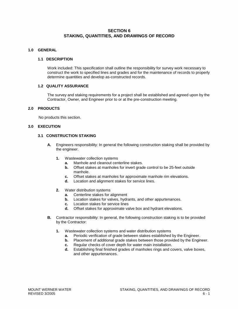
SECTION 6 STAKING, QUANTITIES, AND DRAWINGS OF RECORD
1.0 GENERAL
1.1 DESCRIPTION
Work included: This specification shall outline the responsibility for survey work necessary to construct the work to specified lines and grades and for the maintenance of records to properly determine quantities and develop as-constructed records.
1.2 QUALITY ASSURANCE
The survey and staking requirements for a project shall be established and agreed upon by the Contractor, Owner, and Engineer prior to or at the pre-construction meeting.
2.0 PRODUCTS No products this section. 3.0 EXECUTION
3.1 CONSTRUCTION STAKING
A. Engineers responsibility: In general the following construction staking shall be provided by the engineer.
1. Wastewater collection systems
a. Manhole and cleanout centerline stakes. b. Offset stakes at manholes for invert grade control to be 25-feet outside
manhole. c. Offset stakes at manholes for approximate manhole rim elevations. d. Location and alignment stakes for service lines.
2. Water distribution systems
a. Centerline stakes for alignment b. Location stakes for valves, hydrants, and other appurtenances. c. Location stakes for service lines d. Offset stakes for approximate valve box and hydrant elevations.
B. Contractor responsibility: In general, the following construction staking is to be provided
by the Contractor:
1. Wastewater collection systems and water distribution systems a. Periodic verification of grade between stakes established by the Engineer. b. Placement of additional grade stakes between those provided by the Engineer. c. Regular checks of cover depth for water main installation. d. Establishing final finished grades of manholes rings and covers, valve boxes,
and other appurtenances.
MOUNT WERNER WATER STAKING, QUANTITIES, AND DRAWINGS OF RECORD REVISED 3/2005 6 - 1
3.2 QUANTITY SURVEYS
The Contractor will furnish personnel to assist the Engineer in making such surveys as are necessary to determine the quantities of work performed. Unless waived in writing in each special case, quantity surveys shall be made under the direction of the engineer or his representative. All original field notes, computations and other records taken for the purpose of quantity surveys shall become the property of the Owner and be kept in the custody of the Engineer. Quantity surveys shall be used to the extent necessary in determining the amount of payments due to the contractor.
3.3 NOTIFICATION
The Contractor shall notify the Engineer 48-hours in advance of needed staking. The Contractor shall notify the Engineer immediately upon encountering any know staking errors or if the Contractor suspects a staking error. Any work performed by the Contractor to apparent erroneous staking information shall be at the Contractor’s risk.
3.4 DRAWINGS OF RECORD
A. Drawings: The Contractor will be furnished with a complete set of approved prints of all
contract drawings upon which the Contractor shall maintain a neat and accurate record of all contract work. The Contractor shall promptly record the as-built quantities and dimensions of all contract work as it is performed on this set of prints. At the completion of project work, the entire set of prints plus any additional drawings necessary shall be submitted to the Engineer for final inspection and comment. The Contractor shall correct, amplify, and do all other work as may be required by the Engineer to complete the as-built record in a manner satisfactory to the Engineer.
B. Information required: The Contractor’s record shall include, for example, location of
valves, fittings, connections, service lines, cleanouts, and manholes. Locations are to be established by three point ties to physical objects which will remain undisturbed. Materials and fittings used; relative placement of fittings, with dimensions; depth of water mains, and locations of lines or other important items.
4.0 MEASUREMENT AND PAYMENT
No separate payment will be made for work required under this section.
MOUNT WERNER WATER STAKING, QUANTITIES, AND DRAWINGS OF RECORD REVISED 3/2005 6 - 2
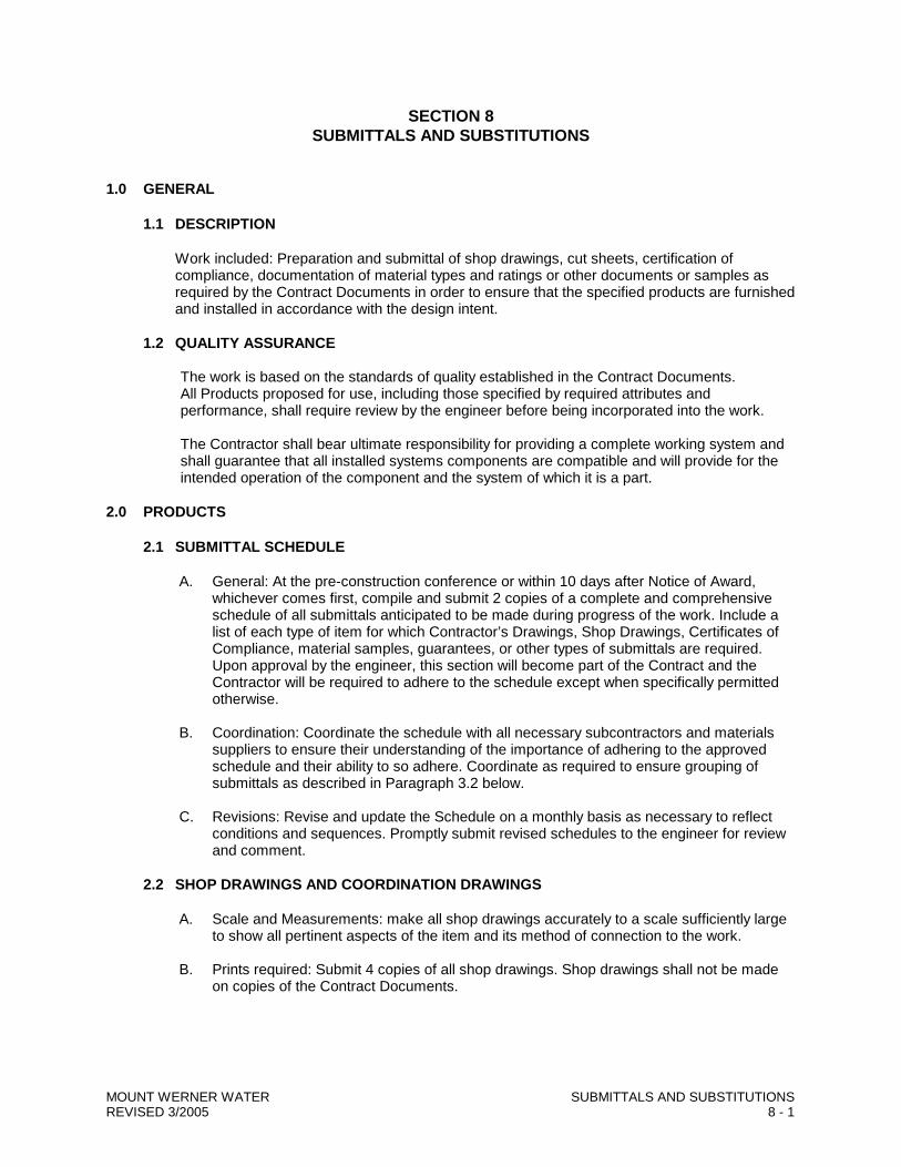
SECTION 8 SUBMITTALS AND SUBSTITUTIONS
1.0 GENERAL
1.1 DESCRIPTION
Work included: Preparation and submittal of shop drawings, cut sheets, certification of compliance, documentation of material types and ratings or other documents or samples as required by the Contract Documents in order to ensure that the specified products are furnished and installed in accordance with the design intent.
1.2 QUALITY ASSURANCE
The work is based on the standards of quality established in the Contract Documents. All Products proposed for use, including those specified by required attributes and performance, shall require review by the engineer before being incorporated into the work. The Contractor shall bear ultimate responsibility for providing a complete working system and shall guarantee that all installed systems components are compatible and will provide for the intended operation of the component and the system of which it is a part.
2.0 PRODUCTS
2.1 SUBMITTAL SCHEDULE
A. General: At the pre-construction conference or within 10 days after Notice of Award, whichever comes first, compile and submit 2 copies of a complete and comprehensive schedule of all submittals anticipated to be made during progress of the work. Include a list of each type of item for which Contractor’s Drawings, Shop Drawings, Certificates of Compliance, material samples, guarantees, or other types of submittals are required. Upon approval by the engineer, this section will become part of the Contract and the Contractor will be required to adhere to the schedule except when specifically permitted otherwise.
B. Coordination: Coordinate the schedule with all necessary subcontractors and materials
suppliers to ensure their understanding of the importance of adhering to the approved schedule and their ability to so adhere. Coordinate as required to ensure grouping of submittals as described in Paragraph 3.2 below.
C. Revisions: Revise and update the Schedule on a monthly basis as necessary to reflect
conditions and sequences. Promptly submit revised schedules to the engineer for review and comment.
2.2 SHOP DRAWINGS AND COORDINATION DRAWINGS
A. Scale and Measurements: make all shop drawings accurately to a scale sufficiently large
to show all pertinent aspects of the item and its method of connection to the work. B. Prints required: Submit 4 copies of all shop drawings. Shop drawings shall not be made
on copies of the Contract Documents.
MOUNT WERNER WATER SUBMITTALS AND SUBSTITUTIONS REVISED 3/2005 8 - 1
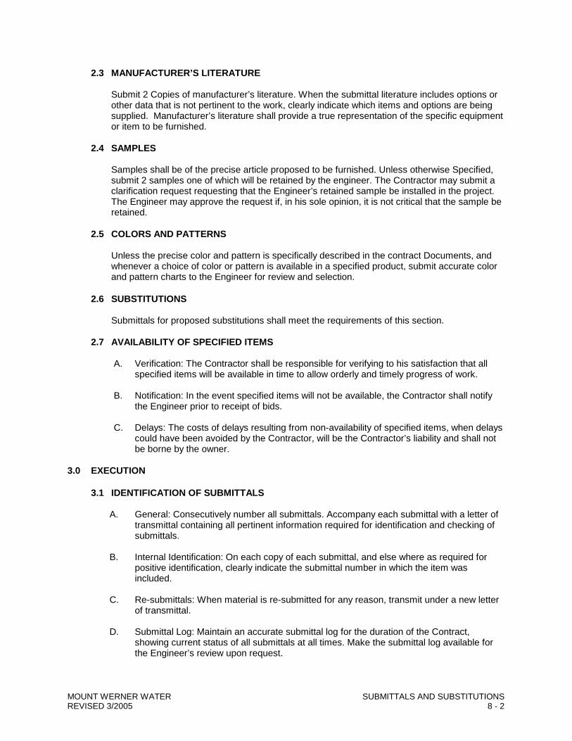
2.3 MANUFACTURER’S LITERATURE
Submit 2 Copies of manufacturer’s literature. When the submittal literature includes options or other data that is not pertinent to the work, clearly indicate which items and options are being supplied. Manufacturer’s literature shall provide a true representation of the specific equipment or item to be furnished.
2.4 SAMPLES
Samples shall be of the precise article proposed to be furnished. Unless otherwise Specified, submit 2 samples one of which will be retained by the engineer. The Contractor may submit a clarification request requesting that the Engineer’s retained sample be installed in the project. The Engineer may approve the request if, in his sole opinion, it is not critical that the sample be retained.
2.5 COLORS AND PATTERNS
Unless the precise color and pattern is specifically described in the contract Documents, and whenever a choice of color or pattern is available in a specified product, submit accurate color and pattern charts to the Engineer for review and selection.
2.6 SUBSTITUTIONS
Submittals for proposed substitutions shall meet the requirements of this section.
2.7 AVAILABILITY OF SPECIFIED ITEMS
A. Verification: The Contractor shall be responsible for verifying to his satisfaction that all
specified items will be available in time to allow orderly and timely progress of work. B. Notification: In the event specified items will not be available, the Contractor shall notify
the Engineer prior to receipt of bids. C. Delays: The costs of delays resulting from non-availability of specified items, when delays
could have been avoided by the Contractor, will be the Contractor’s liability and shall not be borne by the owner.
3.0 EXECUTION
3.1 IDENTIFICATION OF SUBMITTALS
A. General: Consecutively number all submittals. Accompany each submittal with a letter of transmittal containing all pertinent information required for identification and checking of submittals.
B. Internal Identification: On each copy of each submittal, and else where as required for
positive identification, clearly indicate the submittal number in which the item was included.
C. Re-submittals: When material is re-submitted for any reason, transmit under a new letter
of transmittal. D. Submittal Log: Maintain an accurate submittal log for the duration of the Contract,
showing current status of all submittals at all times. Make the submittal log available for the Engineer’s review upon request.
MOUNT WERNER WATER SUBMITTALS AND SUBSTITUTIONS REVISED 3/2005 8 - 2
3.2 COORDINATION OF SUBMITTALS
A. Prior to submittal for approval, use all means necessary to fully coordinate all material including, but not limited to:
1. Determine and verify all interface conditions, catalog numbers, and similar data. 2. Coordinate with other trades as required 3. Clearly indicate all deviations from requirements of the Contract Documents.
B. Grouping of submittals: Unless otherwise specified, make all submittals in groups containing all associated items to ensure that information is available for checking each item when it is received. Partial submittals may be rejected as not complying with the provisions of the Contract Documents and the Contractor shall be strictly liable for all delays so occasioned.
3.3 TIMING OF SUBMITTALS
A. General: Make all submittals far enough in advance of scheduled dates for installation to
provide all time required for reviews, for securing necessary approvals, for possible revisions and re-submittals, and for placing orders and securing delivery.
B. Engineer’s Review Time: In scheduling, allow at least 10 calendar days for review by the
Engineer following receipt of the submittal. C. Delays: delays caused by tardiness in receipt of submittals will not be an acceptable basis
for extensions of the contract completion date.
3.4 ENGINEER’S REVIEW
A. General: Review by the Engineer shall not be construed as a complete check, but only that the general method of construction and detailing is satisfactory. Review shall not relieve the Contractor from the responsibility for errors which may exist.
B. Authority to Proceed: The notations “NO EXCEPTION TAKEN”, “MAKE CORRECTIONS
NOTED”, and others, authorize the contractor to proceed with fabrication, purchase, or both , of the items as noted, subject to the revisions, if any, required by the Engineer’s review comments.
C. Revisions: Make all revisions required by the Engineer. If the Contractor considers any
required revisions to be a change, he shall so notify the Engineer as provided for under “Changes” in the General Conditions. Show each drawing revision number, date and subject in a revision block on the drawing. Make only those revisions directed or approved by the Engineer.
D. Revisions after Approval: When a submittal has been reviewed by the Engineer,
resubmittals for substitution of material or equipment will not be considered unless accompanied by an acceptable explanation as to why the substitution is necessary.
4.0 MEASUREMENT AND PAYMENT
No separate measurement for payment will be made for the work under this section. Its cost shall be considered incidental to the project.
MOUNT WERNER WATER SUBMITTALS AND SUBSTITUTIONS REVISED 3/2005 8 - 3
SECTION 12 MATERIALS, EQUIPMENT AND WORKMANSHIP
1.0 GENERAL
1.1 DESCRIPTION
Work under this Section shall establish the general standards for quality of materials, equipment purchase and installation and general project workmanship.
1.2 QUALITY ASSURANCE
A. All Materials: All materials and equipment supplied for this project shall be new, unused
and correctly designed for the intended application. They shall be of standard first grade quality, produced by expert workmen, and be intended for the use for which they are designed. Materials or equipment which, in the opinion of the Engineer, are inferior or of lower grade than indicated, specified or required will not be accepted.
All material and equipment supplied shall meet specified performance requirements at the
elevation of the project site. Any two or more pieces of material or equipment of the same kind, type or classification,
and being used in similar types of services, shall be made by the same manufacturer. Where intended for use with potable water, materials and methods shall in general, comply
with the appropriate AWWA and NSF standards. B. Equipment: Equipment and appurtenances shall be designed in conformity with ANS,
ASME, IEEE, NEMA and all other generally accepted standards. All equipment supplied shall be of rugged construction and suitable for the intended purpose, under design operating conditions, in the location and climate where they are to be used.
All equipment supplied shall be in accordance with the requirements of the contract
documents. Equipment shall be of the approximate dimensions indicated on the Drawings or as
specified, shall fit in the spaces shown on the drawings with adequate clearance, and shall be capable of being handled through openings provided in the structure for this purpose. Equipment shall be of such design that piping and electrical connections, ductwork, and auxiliary equipment can be assembled and installed without causing major revisions to the location or arrangement of any of the facilities.
Where applicable all equipment shall bear a brass or stainless steel nameplate giving
manufactures rated capacity, head, speed, horsepower, service factor and any other pertinent operating data.
Equipment shall be of sufficient strength to withstand all stresses which may occur during
fabrication, testing, transportation, installation and all conditions of operation. All bearings and moving parts shall be adequately protected against wear by brushings or other approved means and shall be fully lubricated by readily accessible devices. Details shall be designed for appearance as well as utility. Protruding membranes, joints, corner, gear covers and the like, shall be finished in appearance. All exposed welds shall be ground smooth and the corners of the structural shapes shall be mitered.
MOUNT WERNER WATER MATERIAL, EQUIPMENT AND WORKMANSHIP REVISED 3/2005 12 - 1
C. Machinery: Machinery parts shall conform exactly to the dimensions shown on the working Drawings. There shall be no more fittings or adjusting in setting up a machine than is necessary in assembling high grade apparatus of standard design. The equivalent parts of identical machines shall be made interchangeable. All grease lubricating fittings on equipment shall be safeguarded in accordance with the safety codes of the ANS, applicable state and local codes and with the U.S. Department of Labor, Part 1910 Occupational Safety and Health Standards, promulgated under the Occupational Safety and Health Act of 1980 (PL 91-596).
1.3 PRODUCT HANDLING AND STORAGE
All materials and equipment to be incorporated in the work shall be handled and stored by the Contractor in a manner satisfactory to the engineer and in such a way as to prevent damage or theft of the same.
All materials and equipment subject to corrosive damage by the atmosphere if stored outdoors (even though covered by canvas) shall be stored in a building to prevent injury. The building may be a temporary structure on the site or elsewhere, but it must be satisfactory to the engineer.
All material which, in the opinion of the Engineer, have become so damaged as to be unfit for the use intended or specified shall be promptly removed from the site of work, and the Contractor shall receive no compensation for the material or its removal.
All pipe and other materials delivered to the job shall be unloaded and placed in a manner which will not hamper the normal operating of existing facilities or interfere with the flow of necessary traffic or with construction progress.
2.0 PRODUCTS
No products this section 3.0 EXECUTION
General requirements for installation of equipment specified for use on the project shall be as follows:
All equipment shall be installed, equipped and serviced as per the manufacturer’s recommendation except as supplemented or modified by the requirements of these Specifications or as directed by the Engineer.
All equipment shall be leveled, plumbed, aligned and wedged into position to fit connecting piping and assemblies without transmitting stresses to the equipment.
Where applicable, equipment base frames shall be anchored to concrete pads with cast-in-place anchor bolts. Dimensions for equipment pads shall be determined by the equipment manufacturer and shall be shown on all shop drawings. The base frame shall be grouted solid.
All inlet and discharge piping connections to equipment shall include unions for ease of removal and repair. Wastewater from packing shall be piped directly to a drain and not allowed to discharge freely on the floor or elsewhere.
All equipment shall be greased, lubed, oiled and in all ways properly prepared for start-up by the Contractor per the manufacture’s written recommendations. Where required by these Contract Document’s, a qualified service technician shall proved the necessary start-up services.
MOUNT WERNER WATER MATERIAL, EQUIPMENT AND WORKMANSHIP REVISED 3/2005 12 - 2
Ceiling lifting hooks shall be installed above most plant equipment. All hooks shall provide a safety factor of 5 against failure for equipment gross weight.
All concrete work shall be of first grade quality, meeting the requirements specified in these Contract Documents. All floors shall be free from ponding, irregularities and shall drain to the outlets provided.
The Contractor shall provide all labor, tools, equipment and coordination necessary to provide compliance with the Contract Documents for leakage, performance, quantity, thickness, efficiency, etc. of installed materials and equipment.
4.0 MEASUREMENT AND PAYMENT
There shall be no separate measurement or payment for work in this Section. Its cost shall be considered incidental to the work.
MOUNT WERNER WATER MATERIAL, EQUIPMENT AND WORKMANSHIP REVISED 3/2005 12 - 3
SECTION 14 TRAFFIC REGULATION
1.0 GENERAL
1.1 DESCRIPTION
Work under this section shall include the regulation of vehicular and pedestrian traffic during performance of the work. The Contractor shall be responsible for the safe and orderly flow of traffic through and around the project site at all times.
1.2 QUALITY ASSURANCE
Work shall be per:
1. “Flagging an Traffic Control Supervisors’ Training Manual”; Colorado Department of
Highways. 2. “Manual on Uniform Traffic Control Devices” (MUTCD); Federal Highway Administration;
1993. 3. “Colorado Supplement” to the MUTCD.
2.0 PRODUCTS
All warning signs, barricading, and other necessary items shall conform to the above references. 3.0 EXECUTION
3.1 GENERAL
The Contractor shall provide all necessary signs, barricades, lights, and flag persons necessary for the safe and orderly flow of pedestrian and vehicular traffic. Every attempt to keep traffic flow at a normal pace must be made whenever possible. The Contractor shall confine his occupancy of public traveled ways to the smallest space compatible with the efficient and safe performance of the work. Traffic is to be restored to normal flow, whenever feasible, at the end of each working day.
It shall be the Contractor’s sole responsibility to notify the appropriate authorities at least 48 hours in advance of significant changes in traffic patterns or possible hazards due to reductions of travel surface width or other work in public rights of way. The Contractor is to coordinate all detours and temporary road closings with the appropriate authorities.
3.2 SIGNS AND BARRICADES
Properly lighted, adequately sized, concise, legible signs shall be furnished as necessary for the safe regulation of traffic. Any backfilled areas that present a hazard to traffic must be properly protected and signed.
Suitable lighted barriers or barricades shall be furnished by the Contractor and put up and maintained at all times during the night or daytime, around all open ditches, trenches, excavations, or other work potentially dangerous to pedestrians and vehicular traffic. Barricades shall be placed on all sides and throughout the entire length of all open ditches, trenches, excavations, or other work which must be barred to the general public. Barricades shall be properly painted in order to retain a high degree of visibility at all times to vehicular and pedestrian traffic.
MOUNT WERNER WATER TRAFFIC REGULATION REVISED 3/2005 14 - 1
3.3 TRAFFIC CONTROL PLAN
The Contractor shall submit a traffic control plan for all major detours and for all complicated traffic control operations to the Engineer and the applicable regulatory agencies for review and concurrence well in advance of implementation. The plan must be developed by an American Traffic Safety Services Association (ATSSA) certified individual.
3.4 NON-PERFORMANCE
The Owner immediately, and without notice, may furnish, install and maintain barricades or lights if the Contractor fails to comply with the requirements of this section. The cost thereof shall be borne by the Contractor and may be deducted from any amount due or to become due to the Contractor under this contract.
4.0 MEASUREMENT AND PAYMENT
Traffic regulation shall be measured and paid for per the lump sum bid item traffic regulation. A percentage of the total bid amount will be paid as work progresses proportionate to the traffic regulation effort provided for the pay period.
The above payment shall include the cost of all signs, barricades, lights, equipment, tools, and labor incidental or necessary for completion of the work.
If no bid item for traffic regulation is listed, no separate payment will be made for the work under this section. Its cost shall be considered incidental to the project.
MOUNT WERNER WATER TRAFFIC REGULATION REVISED 3/2005 14 - 2
SECTION 15 WATER POLLUTION CONTROL
1.0 GENERAL
1.1 DESCRIPTION
A. Work included: The work under this section shall include all temporary measures to control water pollution and soil erosion as may be specified or directed by the Engineer during the construction of the Work and for such a length of time after completion of the Work as may be required.
B. Related work described elsewhere: Re-vegetation, Section 22.
1.2 QUALITY ASSURANCE
The Contractor shall comply with the requirements of the Colorado “Water Quality Control Act” and amendments thereto, Article 8 of Chapter 25, CRS 1973 and all rules and regulations adopted thereunder as well as the requirements of this section.
1.3 SUBMITTALS
Prior to commencing construction, the Contractor shall submit a written plan for proposed temporary water pollution and soil erosion control measures for the Engineer’s review and approval.
2.0 PRODUCTS
2.1 WATER IMPOUNDMENT FENCE MATERIAL
Temporary water impoundments shall be constructed using Envirofence 100% as manufactured by MIRAFI, Inc. or by using hay bales securely anchored with metal posts, or a combination of both.
2.2 MULCH AND SEED
All re-vegetation shall be in accordance with the requirements or Section 22.
3.0 EXECUTION
In general, all construction activities shall proceed in such a manner so as not to pollute any watercourse, water body, conduit carry water, etc., all in accordance with this specification and to the satisfaction of the Engineer. The Engineer may direct the Contractor to provide immediate temporary pollution or erosion control measures to prevent contamination of adjacent streams, other watercourses, or impoundments.
The Contractor shall be responsible for limiting the surface area of earth materials exposed by construction methods, to immediately provide permanent and temporary pollution control measures to prevent contamination of adjacent watercourses and water bodies, and to minimize erosion of the site and abutting property.
All slopes of stockpiled and excavated materials, all borrow stored on the site, all embankments and/or filling operations sloping into or near watercourses, water bodies, wetlands, etc., and all other disturbed area shall be protected with mulching, seeding or silt control fences. A temporary system of anchored bales of hay or straw or Envirofence shall be placed at or near the toe of all exposed
MOUNT WERNER WATER WATER POLLUTION CONTROL REVISED 3/2005 15 - 1
earth surfaces with a gradient of 25 percent or greater, around the perimeter of the work area and at other locations as the Engineer may direct, until such areas are reduced in grade or permanently stabilized.
The Engineer has the authority to direct the Contractor to divert surface water runoff away from exposed raw earth surfaces through the use of temporary berms, dikes, dams, and diversion channels as considered appropriate.
The Contractor shall at all times have at hand the necessary materials and equipment to provide for early slope treatment and corrective measures to damaged slopes. All damaged areas shall be repaired as soon as possible.
The erosion control features shall be installed and maintained by the Contractor, and shall be checked periodically and after each severe rain storm for damage, until such features are no longer needed. All sediment traps and sediment basins shall have the accumulated sediment and/or clear water regularly removed so also to maintain their storage volume and function.
The Contractor shall be responsible for the preservation of all stream banks within and adjacent to the limits of work. No excavation, stockpiling, or construction equipment will be permitted within 10-feet of the top of any stream bank or water body, unless required for the work shown on the Drawings. Any stream bank disturbed by the contractor’s operations will be rip rapped or otherwise repaired as ordered by the Engineer.
In all cases involving work in a water body, every effort should be made to return the water body to the highest possible standard for aesthetic value, water quality and fish habitat. At stream crossings, the Contractor’s work shall meet the following minimum standards:
a. Sufficient flow of water shall be maintained at all times to sustain aquatic life downstream. b. Any divergence of the stream shall provide a V or dish shaped channel to concentrate flow
during periods of low water. c. Disturbance of the streambed shall be kept to an absolute minimum, and the streambed shall
be returned as nearly as possible to its original condition or better. Where possible, in modifying a streambed, the centerline shall be 8 to 12 inches lower than the toe of the channel bank to concentrate the flow of water.
d. Disturbed banks shall be returned to original slope, and rip rapped and/or planted with suitable
grasses, trees, and shrubs so as to prevent erosion. e. Any dike or cofferdam required to facilitate construction shall be erected in such a manner that
stream flow will not be sufficiently reduced to endanger fish life downstream. Such dike or cofferdam shall be erected of materials that will not contribute substantially to the turbidity or siltation of the stream.
Care shall be taken to prevent or reduce to a minimum any damage to the water body from pollution by debris, sediment or other materials, or from the manipulation of equipment and/or materials in or near such water bodies. Water that has been used for washing or processing, or that contains oils or sediments that will reduce the quality of the water in the stream shall not be directly returned to the stream. Such waters will be diverted through a settling basin or filter before being directed into the water body.
If the water is taken from a water body for construction purposes and an impounding structure is necessary, such structure shall be erected in a manner causing the least possible disturbance to the water body.
MOUNT WERNER WATER WATER POLLUTION CONTROL REVISED 3/2005 15 - 2
4.0 MEASUREMENT AND PAYMENT
No separate payment will be made for the work under this Section. Its cost shall be considered incidental to the Project.
MOUNT WERNER WATER WATER POLLUTION CONTROL REVISED 3/2005 15 - 3
SECTION 16 DUST CONTROL
1.0 GENERAL
1.1 WORK
A. Work included: the work under this section shall include all equipment, labor and materials necessary to control dust relating to or resulting from performance of the project work.
B. Related work described elsewhere: In addition to the requirements described herein,
comply with specific requirements for dust control as may be detailed in other sections of these specifications or as noted on the Drawings.
1.2 QUALITY ASSURANCE
A. Standards: Comply with all pertinent requirements of Federal, State or Local agencies
that have jurisdiction over dust control procedures and additives used to aid in dust abatement.
B. Inspection: The Engineer, Contractor and Owner shall periodically review the adequacy of
dust control efforts and procedures to assure they are satisfactorily meeting the needs of the project.
1.3 SUBMITTALS
A. Dust Control Procedures: Prior to commencing the project work, the Contractor shall
meet with the Owner and Engineer to review the proposed dust control plan and methods to assure their compliance with the specific needs of the project.
B. Additives: All Additives proposed for use as an aid in dust control other than specified in
Section 2.2 shall be reviewed with the Engineer prior to their application. Manufacturers literature along with recommended application rates shall be provided.
2.0 PRODUCTS
2.1 WATER
Water used for dust control shall be non-polluted. The use of water from fire hydrants is not allowed.
2.2 CHEMICAL ADDITIVES
Calcium Chloride: Shall to conform to the requirements of AASHTO M 144 (ASTM-D-98) except that either pellet or flake shall be acceptable. Magnesium Chloride may also be used.
3.0 EXECUTION
3.1 GENERAL
During the performance of the work required by these specifications or any operations appurtenant thereto, the Contractor shall furnish all labor, equipment, materials, and means required, and shall carry out proper and efficient measures wherever and as often as necessary
MOUNT WERNER WATER DUST CONTROL REVISED 3/2005 16 - 1
to reduce the dust nuisance, and to prevent dust which has originated from his operations from damaging landscaping, dwellings, air quality or causing a nuisance to persons.
3.2 WATER
A. Procurement: The Contractor shall be responsible for arranging for the necessary supply
of suitable water for dust abatement. B. The Contractor shall apply water and/or water with additives on all access and haul roads,
excavations, surfaces or filled trenches, stockpiles, waste areas, and other work areas as may be necessary to adequately control dust.
C. Quantity: The quantity of water required for adequate dust control is variable and depends
on climatic factors, soil types, and potential for nuisance. Dust control requirements shall be as discussed, established, and reviewed periodically during the course of project work.
3.3 WORK AREAS
The Contractor shall make a reasonable effort to keep work areas and adjacent areas free of excessive dirt and mud that unnecessarily contribute to a dust nuisance.
4.0 MEASUREMENT AND PAYMENT
Payment for all costs of equipment and materials required to provide dust control shall be made on a lump sum basis per the Dust Control Bid Item. A percentage of the total bid amount will be paid as work progresses proportionate to the dust control effort provided for the pay period.
If no separate bid item is provided, no separate payment will be made for the work under this section. Its cost shall be considered incidental to the project.
MOUNT WERNER WATER DUST CONTROL REVISED 3/2005 16 - 2
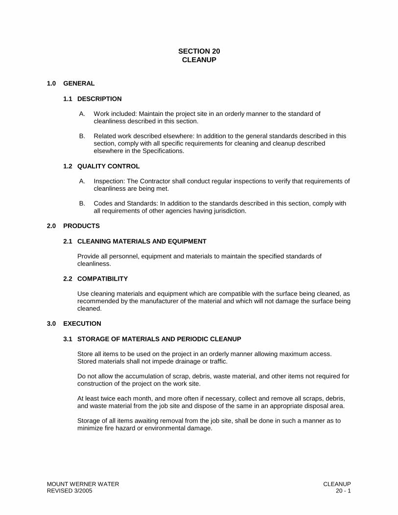
SECTION 20 CLEANUP
1.0 GENERAL
1.1 DESCRIPTION
A. Work included: Maintain the project site in an orderly manner to the standard of cleanliness described in this section.
B. Related work described elsewhere: In addition to the general standards described in this
section, comply with all specific requirements for cleaning and cleanup described elsewhere in the Specifications.
1.2 QUALITY CONTROL
A. Inspection: The Contractor shall conduct regular inspections to verify that requirements of
cleanliness are being met. B. Codes and Standards: In addition to the standards described in this section, comply with
all requirements of other agencies having jurisdiction. 2.0 PRODUCTS
2.1 CLEANING MATERIALS AND EQUIPMENT
Provide all personnel, equipment and materials to maintain the specified standards of cleanliness.
2.2 COMPATIBILITY
Use cleaning materials and equipment which are compatible with the surface being cleaned, as recommended by the manufacturer of the material and which will not damage the surface being cleaned.
3.0 EXECUTION
3.1 STORAGE OF MATERIALS AND PERIODIC CLEANUP
Store all items to be used on the project in an orderly manner allowing maximum access. Stored materials shall not impede drainage or traffic.
Do not allow the accumulation of scrap, debris, waste material, and other items not required for construction of the project on the work site.
At least twice each month, and more often if necessary, collect and remove all scraps, debris, and waste material from the job site and dispose of the same in an appropriate disposal area.
Storage of all items awaiting removal from the job site, shall be done in such a manner as to minimize fire hazard or environmental damage.
MOUNT WERNER WATER CLEANUP REVISED 3/2005 20 - 1
3.2 FINAL CLEANUP
A. Definition: Except as otherwise specifically provided, “clean” shall be defined as the level of cleanliness generally provided by skilled cleaners using commercial quality building or site maintenance equipment and materials.
B. General: Upon completion of the work, remove all tools, surplus materials, equipment,
scraps, debris, and waste from the work site. C. Site: Unless specifically authorized otherwise by the engineer broom clean all paved
areas on the site and all public paved areas adjacent to the site which were contaminated because of the work. Completely remove all resulting debris.
Graveled Parking or driveway areas within or adjacent to the work site which have had excavated or other loose materials stockpiled on them shall be scraped clean down to the original surface. Replacement of gravel materials may be required to restore the surface to its original condition. Grassed areas within or adjacent to the work site shall be scraped and raked clean to the original grass or soil level. All stones and other loose debris shall be picked up and removed.
D. Timing: Schedule final cleaning and cleanup to enable the Owner to accept a clean,
finished project.
4.0 MEASUREMENT AND PAYMENT
There shall be no separate payment for the work covered in this Section, its cost shall be considered incidental to the project.
MOUNT WERNER WATER CLEANUP REVISED 3/2005 20 - 2
SECTION 22 REVEGETATION
1.0 GENERAL
1.1 DESCRIPTION
Work included: This specification shall govern the work associated with the re-vegetation of all areas disturbed by the Contractor. Re-vegetation shall include application of native or lawn seed, fertilizer, sod, mulch and soil retention blanket.
1.2 SUBMITTALS
A. Seed and Fertilizer: The Contractor shall submit the seed and fertilizer mix proposed for
use on the project for approval prior to application. B. Sod: The Contractor shall submit a sample of the sod he proposes to furnish. The
sample shall serve as the standard for the project. Sod furnished which is not compatible with the standard sample will not be accepted.
C. Mulch and Soil Retention Blanket: Suppliers shall certify that laboratory and field testing
of their product has been accomplished and that it meets the material requirements contained herein. Test results shall be made available to the Engineer upon written request.
2.0 PRODUCTS
2.1 MATERIALS
A. Native Seed: Shall consist of a mixture of the following:
B. Fertilizer: The fertilizer shall be standard brand commercial lawn fertilizer having a
minimum of 18% available nitrogen, 46% phosphorous and 0% potash (18-46-0). C. Lawn Seed: Seed to be applied to lawn areas shall be a mixture of 1/4 lb. PLS Merion
Bluegrass, 1/4 lb. PLS Bluegrass and 1/2 lb. PLS Perennial Rye. D. Sod: Bluegrass sod shall be nursery grown, 99% Kentucky Bluegrass and 99% weed
free. The 1% allowable weed shall not include any undesirable perennial or annual grasses or plants. Soil thickness of sod cuts shall not be less than 3/4 inch nor more than 1 inch. Sod shall be cut in uniform strips 18 inches in width and not less than 6 feet long.
MOUNT WERNER WATER REVEGETATION REVISED 3/2005 22 - 1
E. Mulch:
1. Straw mulch: shall consist of straw of oats, barley, wheat, or rye which does not contain seed of noxious weeds. Straw in such an advanced stage of decomposition as to smother or retard the normal growth of the grass, or old dry straw which breaks in the crimping process in lieu of bending will not be accepted.
2. Hay mulch: shall consist of good clean field or marsh hay which does not contain
seed or noxious weeds. Hay in such an advanced stage of decomposition as to smother or retard the normal growth of grass will not be accepted.
3. Hydraulic mulch: Wood cellulose fiber for hydraulic mulch shall not contain any
substance or factor which might inhibit germination or growth of grass seed. It shall be dyed an appropriate color to allow visual metering of its application. The wood cellulose fibers shall have the property of becoming evenly dispersed and suspended when agitated in water. When sprayed uniformly on the surface of the soil the fibers shall form a blotter-like ground cover which readily absorbs water and allows infiltration to the underlying silt. Weight specifications from suppliers, and for all applications, shall refer only to air dry weight of the fiber, a standard equivalent to 10 percent moisture. The mulch material shall be supplied in packages having a gross weight not in excess of 100-pounds and shall be marked by the manufacturer to show the air dry weight content.
F. Soil Retention Blanket:
1. Jute: The blanket shall consist of heavy jute mesh of a uniform open plain weave of
unbleached yarn. The yarn shall be of a loosely twisted construction having an average twist of not less than 1.6 turns per inch and shall not vary in thickness by more than one-half its normal diameter. The jute mesh shall be furnished in approximately 90 pound rolled strips and shall meet the following requirements:
a. Length - approximately 75 yards b. Width - 48-inches plus 1-inch; 78 warp ends per width of cloth; 41 weft ends per
yard. c. Weight of cloth to average 1.22-pounds per linear yard with a tolerance of plus
or minus 5 percent.
2. Plastic Net: The plastic net shall be a biodegradable extruded oriented net with a rectangular mesh opening of approximately 1.5 x 1 strands per square inch and a nominal weight of 2.6 pounds per 100 square feet.
3. Pins and Staples: Pins or staples shall be made of wire .091 inch or larger in
diameter. “U” shaped staples shall have legs 6-inch long and 1-inch crown. “T” shaped pins shall have a minimum length of 8-inches after bending. The bar of the “T” shall be at least 4 inches long with the single wire and bent downward approximately 3/4-inch.
3.0 EXECUTION
3.1 PREPARATION
A. General: In all disturbed areas, topsoil is to be salvaged and replaced. Prior to any re-vegetation activity, the soil shall be tilled to provide at least 2 to 4-inches of loose surface.
B. Sod: Preparatory to sodding, all irregularities in the ground surface shall be removed.
Sticks, stones, debris and other similar material more than 1/2-inch in diameter shall be
MOUNT WERNER WATER REVEGETATION REVISED 3/2005 22 - 2
removed. Any objectionable depressions or other variances from a smooth grade shall be corrected Areas to be sodded shall be smooth before any sodding is done
3.2 APPLICATION
A. Native Seed:
1. 3:1 Slopes or flatter: Seeding shall be accomplished by means of an approved drill-
type seeder at a rate of 20lbs. per acre PLS or broadcast at 40 lbs. per acre PLS. 2. Slopes steeper than 3:1: Seeding shall be accomplished by means of an approved
drill-type seeder whenever possible. Otherwise seed shall be sown with an approved broadcast-type seeder. The seeded area shall then be raked lightly to provide about 1/2-inch of cover over the seed unless hydraulic broadcasting and mulching is used.
3. Seeding Period and Maintenance: It is preferred that native seeding be
accomplished before May 15th or after August 15th. Seeding may be done between May 15th and August 15th but this may require considerable additional watering by the Contractor between May 15th and August 15th, the Contractor shall be responsible for maintaining and adequately watering seeded areas during the warranty period of five weeks after the time of seeding. Areas in which there is not a satisfactory stand at the expiration of the five week period shall be reseeded once to provide acceptable re-vegetation at the end of the warranty period Seed shall not be sown during windy weather or when the ground is frozen or otherwise un-tillable.
B. Fertilizer: Fertilization is applicable on jobs only when a separate bid item is included in
the Bid section. The fertilizer shall be tilled into the top 2-inches of the soil at a rate of 300 pounds per acre.
C. Lawn Seed: Seeding shall be accomplished by means of an approved broadcast-type
seeder at a rate of 1-pound per 300 sq. ft. PLS. The seeded area shall then be raked to provide about 1/4-inch of cover over the seed unless hydraulic broadcasting and mulching is used. Seed shall not be sown during windy weather or when the ground is frozen or otherwise un-tillable.
The Contractor shall be responsible for maintaining and watering seeded lawn areas for a
period of five weeks after the time of seeding. The Contractor shall guarantee that a stand of grass exists after the five week period. If areas or patches exist without a satisfactory stand of grass, the Contractor shall reseed and maintain until a satisfactory stand exists.
D. Sod: The sod shall be laid by staggering joints. On any slopes, the sod shall run parallel
to a 90 degree angle to the slope. After installation the sod shall be thoroughly soaked.
1. After soaking, the sod shall be permitted to dry to the point where it is still set enough for effective rolling. It shall then be rolled in two directions with a lawn roller weighing not less then 150- pounds to secure a tight bond of sod to subgrade and between strips.
2. The Contractor shall be responsible for maintaining and watering sodded areas for a
period of five weeks after the placement of sod. The Contractor shall guarantee the sod and any areas of dead or dying sod shall be replaced and maintained until it is self-sufficient.
MOUNT WERNER WATER REVEGETATION REVISED 3/2005 22 - 3
E. Mulching:
1. General: All mulching procedures shall be done after the seeding operation is completed and not in conjunction with seeding.
2. Hay or straw mulch: Hay or straw shall be applied to the seeded surface at a rate of
1 1/2 to 2 tons per acre and shall be crimped into the soil with approved equipment. Hay shall not be used as mulching material in lawn areas. On steep slopes where crimping is not possible, a tackifier, such as Terra Tack or J-Tak shall be applied at a rate of 120 lbs./acre in lieu of crimping. An asphaltic tackifier shall not be acceptable.
3. Hydraulic mulching: The hydraulic mulching material shall be spray applied to the
seeded area at a rate of 1 ton/acre. Hydraulic mulching shall not be done in the presence of free surface water resulting from rain, melting snow or other causes.
F. Soil Retention Blanket:
The tackifier included in the mulching specification shall not be necessary where a soil retention blanket is required. The blankets shall be placed immediately after seeding and mulching operations have been completed in each location as specified on the Plan. The material shall be applied smoothly but loosely on the silt surface without stretching. Workers should avoid, as much as possible, walking directly on the seedbed either before or after the mesh is applied. The up slope end of each piece of mesh shall be buried in a narrow trench six (6) inches deep. After the mesh is buried, the trench should be tamped firmly closed. In cases where one roll of mesh ends and a second roll starts, the up slope piece should be brought over the buried and of the second roll so that there is a 12-inch overlap to form a junction slot. Where two or more widths of mesh are applied side by side, an overlap of at least four (4) inches must be made. Check slots should be made before the mesh is rolled out. A narrow trench should be dug across the slope perpendicular to the direction of flow. A piece of mesh, cut the same length as the trench, is folded lengthwise. The fold is placed in the trench and the trench is tamped closed. The portion of the mesh remaining above ground is unfolded and laid flat on the soil surface. Check slots will be spaced so that one check slope or junction slot occurs within each 50-feet of slope. Overlaps which run down the slope, outside edges and centers shall be of staples down the center as well as along each edge. Check slots and junction slots will be stapled across at 6-inch intervals. For extra hard soil, use sharp-pointed, hardened steel, 3-inch fence type staples. Matting must be spread evenly and smoothly and be in contact with the seeded area at all points. It shall be pressed into the soil with a light lawn roller or by a similar method. The Contractor shall maintain the mesh areas until all work on the entire Contract has been completed and accepted. Maintenance shall consist of the repair of areas damaged by erosion, wind fire, or other causes. Such areas shall be repaired to e-establish the condition and grade of the soil prior to application of the mesh and shall be re-fertilized, reseeded and re-mulched as directed.
MOUNT WERNER WATER REVEGETATION REVISED 3/2005 22 - 4
4.0 MEASUREMENT AND PAYMENT
A. NATIVE OR LAWN SEED APPLICATION
Payment shall be per acre seeded per the appropriate Bid item and is to include all work related to preparation and seed application The Contractor shall supply the Engineer with all weight and mixture tickets for native seeding materials used.
B. FERTILIZER
Payment shall be per acre fertilized per the appropriate Bid item and is to include all work related to preparation and fertilizer application. The Contractor shall supply the Engineer with weight tickets for fertilizer used.
C. SOD
Payment shall be made per square yard per the appropriate Bid item and is to include all work related to preparation and installation.
D. MULCH
Payment for mulch application shall be per acre mulched per the appropriate Bid item. The Contractor shall supply the Engineer with weight verification for all mulch materials used.
Areas not properly mulched or damaged due to the Contractor’s negligence, shall be repaired and re-mulched in an acceptable manner at the Contractor’s expense. Mulch removed by circumstances beyond the Contractor’s control shall be repaired and re-mulched as ordered. Payment for this corrective work, shall be at the unit Bid price.
E. SOIL RETENTION BLANKET
Payment for soil retention blanket shall be per acre covered per the appropriate Bid item. The Contractor shall supply the Engineer with material verification for all retention blanket used.
4.1 LIMITATIONS
The Contractor will not be paid for re-vegetation of disturbed areas which resulted from the Contractor’s carelessness or negligence in performing the Work.
MOUNT WERNER WATER REVEGETATION REVISED 3/2005 22 - 5
SECTION 24 TRENCHING, BEDDING AND BACKFILL
1.0 GENERAL
1.1 DESCRIPTION
Work included: Excavation, dewatering, preparation of the trench bottom; installation of foundation, bedding, and shading material; backfill, and disposal of waste material for the installation of pipelines, manholes, and their related appurtenances.
1.2 QUALITY ASSURANCE
Reference: Standard Specifications for Road and Bridge Construction, State Department of Highways, Division of Highways, State of Colorado herein called Standard Specifications.
The Contractor shall conduct compacting tests as necessary to monitor the installation procedure and assure the quality of the work.
Periodic compacting tests may also be performed by the Engineer. The Contractor shall assist the Engineer as necessary to complete the testing and shall provide a safe trench for the Engineer.
1.3 SUBMITTALS
Samples: Supply samples of all imported material to the Engineer if requested.
1.4 DEFINITIONS
A. Earth excavation: shall include all soils and loose, broken and laminated ledgerock or
stones and boulders which can be reasonably ripped, broken, and removed with skillfully operated, suitably powered excavating equipment in good operating condition having a bucket capacity of 3/4 cubic yard.
B. Rock excavation: shall include all solid rock masses which cannot be excavated as
specified under “Earth Excavation” and isolated boulders exceeding 1 cubic yard in size. C. Unsuitable material: shall include all materials that contain roots, debris, organic, frozen,
unstable or unshapable materials or stones having a maximum dimension of 12-inches or greater and that are determined by the Engineer as unsuitable for providing a proper foundation or backfill.
2.0 PRODUCTS
2.1 MATERIALS
A. Foundation Materials:
1. Imported
a. 3/4 inch minus. Class 6 Aggregate Base Course, Section 703 of the Standard Specifications (Dry conditions only).
b. 3/4 inch washed. Number 67 Coarse Aggregate for Concrete, Section 703 of
the Standard Specifications.
MOUNT WERNER WATER TRENCHING, BEDDING AND BACKFILL REVISED 04/2009 24 - 1
B. Bedding And Shading Materials:
1. Use of Native Bedding and Shading materials is not allowed.
2. Dams of impervious material to be approved by the Engineer, are to be placed every
50’ of pipe laid to a height of 2’ above the top of pipe and spanning the width of the trench , to prevent the flow of ground water along the pipe. Ground water drains can only be used in sewer main trenches and are not allowed in water main trenches.
3. Imported
a. 3/ 4 inch minus: Class 6 Aggregate Base Course per Section 703 of the Standard Specifications (Dry conditions only).
b. 3/4 inch washed: Number 6 or Number 67 Coarse Aggregate for Concrete per
Section 703 of the Standard Specifications. c. 3/8 inch screened rock or Squeegee Sand, with 100% of the material passing
a 3/8 inch screen and 0-3% passing a No. 200 screen.
C. Backfill Materials:
1. Native Material: Shall include all material not classified as unsuitable and material that meets the compaction and density requirements.
2. Imported Pit Run: Class 3 Aggregate Base Course per Section 703 of the Standard
Specifications with the following modifications. Material to be 6 inch minus reasonably well graded pit or back run material.
3.0 EXECUTION
3.1 TRENCH EXCAVATION
A. General: Limit operations to as small an area as possible in order to minimize damage to
adjacent property. If necessary clear and grub the area to be excavated. In areas where topsoil exists remove and salvage the topsoil for replacement. Keep topsoil segregated from other excavation materials.
The maximum amount of trench left open at one time shall be limited to 100-feet or such length as the Engineer considers reasonable and necessary. No trench shall be left open over night unless specified otherwise in the Special Provisions. A guide for desirable trench width at the top of the pipe shall be the nominal diameter of the pipe plus 12-inches on each side of the pipe. All utility lines and water courses met shall be maintained and provided for by the Contractor without damage, or nuisance to other parties. Shoring, bracing, sheeting, other trench support methods, and trench boxes shall be used when necessary to protect the work, property and persons. The need, appropriateness and adequacy of all such devices shall be the responsibility of the Contractor.
B. Alignment and Grade: The trench shall be excavated so that the pipe can be installed to
the alignment and grade indicated on the drawings or specified. Under certain field conditions, Mount Werner Water may authorize a water main to be installed with less than
MOUNT WERNER WATER TRENCHING, BEDDING AND BACKFILL REVISED 04/2009 24 - 2
or more than the specified minimum cover. Authorization must be granted prior to installation. All such authorizations will be provided in writing.
It is the Contractor’s responsibility to plan far enough in advance of pipelaying operations to allow grade adjustments to be implemented to provide proper clearances when crossing existing utilities.
In subdivision work, or other work requiring changes to existing grade along the centerline of a proposed pipeline, the changes shall be made to subgrade elevation prior to installation of the line.
C. Dewatering: The Contractor shall provide all necessary dewatering equipment and
procedures necessary for excluding and removing water from trenches, and other parts of the work.
The Trench shall be maintained dry so that the work may be completed efficiently, and pipes can be laid, joined, bedded, inspected and backfilled in dewatered conditions. The pipe shall not be used to dewater the trench. No water shall be allowed to flow over or rise upon fresh concrete or mortar, and no water shall be allowed to enter the pipe. The water shall be disposed of by the Contractor in accordance with the Contract Documents and applicable laws and regulations. The Contractor is responsible for obtaining all necessary dewatering or discharge permits and complying with their requirements.
3.2 FOUNDATION
A. General: Verify that a sound stable trench bottom free from soft, lose, rocky, excessively
hard or other unsuitable native material exists before proceeding B. Required Foundation: Install imported foundation material at all locations specifically
required by the Drawings or Specification. C. Unsuitable Foundation: Where unsuitable foundation is encountered over excavate the
trench bottom to the depth authorized by the Engineer and bring the foundation to grade with the appropriate imported foundation material authorized by the Engineer and compacted in lifts to 90 percent of maximum dry density.
3.3 BEDDING AND SHADING
A. General: Holes for pipe bells shall be provided at each joint. Bell holes shall be no larger
than necessary for joint assembly and assurance that the pipe barrel will lie flat on the trench bottom. Generally, 2-inches of clearance beneath the joint is desired. Push-on type joints require minimum depressions for bell holes. In no case shall the bell support the weight of the pipe at the time of shading and backfill. Under no circumstances shall the pipe be permanently joined in the trench until the trench bottom has been fine graded to provide uniform pipe support at the required invert elevation.
B. Required Embedment: Imported bedding and shading materials are required for all main-
line pipes and appurtenances. C. Procedures and Bedding and Shading: The following procedure shall be used for all types
of pipe. Special care is required in the embedment Zone to assure proper filling and compaction of materials beneath pipe haunches and to avoid displacing or damaging the pipe. Bedding and shading materials shall be placed in a minimum of two lifts. The thickness of the first lift shall not exceed the pipe spring line. Following placement of the
MOUNT WERNER WATER TRENCHING, BEDDING AND BACKFILL REVISED 04/2009 24 - 3
first lift a “tee bar” shall be used to compact loose material under the pipe haunches. The use of the end of a shovel handle to compact under pipe haunches is not considered an acceptable alternative to a “tee bar”. Mechanical compaction may be required at the first lift as well as succeeding lifts for pipe diameters larger than 12-inches or where dictated by trench width.
Depending on the diameter of the pipe being installed, installation of shading materials may require a single lift or multiple lifts. Lift thickness from the spring line or top of bedding to the top of shading shall not exceed 18-inches. Shading Zone materials shall be placed by hand shoveling, or by careful placement with a Backhoe. Dumping or shoving excavated materials over the trench sidewall, and “chipping” of soil from the top of the trench are not considered acceptable means of shading the pipe. Shading Zone materials shall be compacted to 92 percent of maximum dry density. The method of compaction used by the Contractor to obtain the required density is subject to the Engineer’s review. If the specified compaction is not being obtained, the Contractor will be required to modify his compaction procedures to meet specified requirements. This may require the use of other types of compaction equipment or a reduction in size of lifts being compacted.
Any damages to the pipe that occurs from improper compaction procedures or the use of mechanical compaction too close to the pipe shall immediately be repaired by the Contractor. If compaction equipment which is narrower than full trench width is used, the equipment shall be operated first on each side of the pipe between the edge of the pipe and the trench walls and then centered over the pipe.
Horizontal placement of bedding and shading shall extend the full trench width to undisturbed trench width to undisturbed trench wall material.
3.4 TRENCH BACKFILL
A. General: Backfill materials shall be placed in lifts and compacted to 95 percent. Road
crossings will in general, be backfilled with imported material. All excavation and backfill within the City Right of Way shall follow all current City requirements at the time of construction.
Salvaged topsoil shall be replaced to its approximate original depth in all open areas and areas
to be re-vegetated. B. For Manholes Located in Gravel or Paved Areas: Backfill materials shall be compacted to
95 percent in lifts recommended not to exceed 6-inches. C. Deviations of material moisture content:
1. Excessive moisture content: The Contractor shall attempt to dry wet backfill material
to a moisture content suitable for backfilling. If wet native backfill cannot be compacted to the specified requirements after reasonable drying effort by the Contractor, the Engineer may waive the compaction requirement, or may authorize the Contractor to use imported backfill material. Where only the upper portion of the trench section is backfilled with imported material the Contractor shall install geotextiles as authorized by the Engineer to separate the imported and native materials.
2. Insufficient moisture content: Where compaction requirements cannot be met
because of insufficient moisture content, the Contractor will be required to add moisture to the material as required for proper compaction.
MOUNT WERNER WATER TRENCHING, BEDDING AND BACKFILL REVISED 04/2009 24 - 4
D. Flooding and Jetting of Trenches: Flooding or jetting of trenches shall not be permitted.
3.5 WASTE
It shall be the Contractor’s responsibility to remove all excess materials or unsuitable materials remaining from excavation, trenching or other work and dispose of the same in compliance with all applicable laws and regulations.
3.6 FIELD QUALITY CONTROL
A. Compaction: The degree of bedding or backfill compaction specified shall be 95 percent
of maximum dry density as determined by ASTM D 1557, Modified Proctor. The moisture content of bedding or backfill materials shall be within ± 2.0 percent of optimum moisture as determined by ASTM D 1557.
Compaction testing shall include moisture density relations, and density in place. If
compaction testing, or other visual observations, indicate the possibility of inadequate compaction at a lower depth, the Engineer may require the Contractor or re-excavate a lower depth to conduct additional testing.
When requested by the Engineer the Contractor shall proof roll the trench with a loaded
front end loader or truck of sufficient size to determine if soft spots exist. If the tests indicate inadequate compaction, the Contractor shall re-compact the material.
In cases where there is repeated failure to achieve the required state of compaction, the Engineer may require that the backfill be removed and re-compacted in 6-inch lifts or replaced with imported material at the Contractor’s expense.
Testing frequency shall be as required to assure the completed work meets specifications
but shall be no less than the following:
1. In the City of Steamboat Springs Right-of-Way – use the City of Steamboat Springs testing frequency specifications.
2. Out of the City of Steamboat Springs Right-of-Way - An average of one test for
every other lift per type of material placed per 250 linear foot of trench. Additional testing is recommended near manholes, valve boxes and key fill areas.
B. Testing Quality of Materials: All material proposed to be imported from off site shall be
sampled and tested by the Contractor. Sampling procedures shall result in samples that are representative of the actual materials delivered to the project site.
1. Class 6 Aggregate Base Course shall be tested for conformance with section
703.03 of the Standard Specifications.
2. Washed rock shall be tested for gradation.
3. Imported Pit Run shall be tested for AASHTO soil classification plasticity index, liquid limit and gradation.
C. Trench Settlement:
1. General: Variations in soil type and moisture conditions along with inconsistencies in compactive effort may cause settlement to occur in portions of the backfill. The specified compaction requirements shall be considered a minimum. Spot testing
MOUNT WERNER WATER TRENCHING, BEDDING AND BACKFILL REVISED 04/2009 24 - 5
for in place density by the Engineer during construction shall not relieve the contractor of the responsibility to assure that the trench backfill does not settle beyond the limits established below. The Contractor shall be responsible for repair of areas of excessive settlement.
2. Measurement: Measurement of settlement shall generally take place in July or
August, one winter season following completion of trench backfill. 3. Limits: The following limits to trench backfill settlement shall apply.
a. Asphaltic Concrete Paved Areas: Settlement greater than 1/2 inch but less
than 1-1/2 inches shall be repaired by removing the asphalt to a minimum of 2 feet on either side of the settled area and replacing it with a new, thicker section of asphalt to produce a final level surface. Settlement greater than 1-1/2 inches shall be repaired by removing the asphalt and recompacting or replacing the trench backfill and gravels then applying a new asphalt surface.
b. Gravel Surfaces: The Contractor shall add additional compacted gravel to
trenches where settlements are less than 1-1/2 inches. In cases where the settlement is greater than 1-1/2 inches the Contractor shall be required to replace and recompact backfill material as necessary.
4. Warranty: When settlement of trenches necessitates repair, the warranty period for
the trench repairs shall be extended one year beyond the time of the repairs. 4.0 MEASUREMENT AND PAYMENT
4.1 TRENCH EXCAVATION AND BACKFILL
A. NATIVE MATERIALS: No measurements or separate payment will be made for excavation and backfill of native materials. The costs for this work shall be included in the Prices bid for the item being installed, except that rock excavation will be paid for as described below.
B. REQUIRED FOUNDATION AND EMBEDMENT: No measurements or separate payment
will be made for excavation and backfill with imported foundation or bedding and shading materials when the materials are shown or specified as part of the standard installation. The costs for this Work shall be included in the Prices bid for the item being installed, except that rock excavation will be paid for as described.
C. IMPORTED FOUNDATION ZONE MATERIALS: Measurement and payment for removal
of unsuitable foundation material and replacement with imported material shall be per the Unit Price per Cubic Yard measured by the length of material installed times the payment width limit shown on the Drawings times the actual authorized thickness of material replaced under the item Foundation Zone by material type.
D. IMPORTED BEDDING AND SHADING MATERIAL: Measurement and payment for
imported bedding and shading material shall be made at the Unit Price per Cubic Yard measured by the length of material installed times the average width authorized times the actual depth of material shown on the drawings times the actual depth of material authorized less the volume of the pipe installed per the Bedding Zone or Shading Zone item by material type.
E. IMPORTED BACKFILL: Measurement and payment for imported backfill shall be per the
Unit Price per Cubic Yard measured by the length of material installed times the width
MOUNT WERNER WATER TRENCHING, BEDDING AND BACKFILL REVISED 04/2009 24 - 6
authorized times the actual authorized thickness of material replaced under the item Imported Backfill.
F. ROCK EXCAVATION: Measurement and payment for rock excavation shall be in addition
to any payment received for other types of excavation and shall be at the Unit Price per Cubic Yard based upon the quantity of material authorized removed measurements in place under the item Trench Rock Excavation. The maximum payment width shall not exceed the trench payment width shown on the Drawings. The maximum payment depth shall not exceed 6 inches below the pipe invert or manhole bottom. The Contractor shall notify the Engineer prior to excavating rock to allow measurements or rock to be verified. Failure to do so will result in non-payment for all rock excavated prior to the engineer’s confirming measurements.
MOUNT WERNER WATER TRENCHING, BEDDING AND BACKFILL REVISED 04/2009 24 - 7
SECTION 26 PAVEMENT REMOVAL AND REPLACEMENT
1.0 GENERAL
1.1 DESCRIPTION
A. Protection of existing pavement. B. Removal and replacement of pavement structure that may include surface, base, and
subbase courses as required for trench, and test hole excavation or as other wise required by the Engineer.
C. Installation, and removal of temporary pavement structure consisting of base course.
1.2 QUALITY ASSURANCE
Refer to Sections 401.01 to 401.20 of the current edition of the Standard Specifications for Road and Bridge Construction, State department of Highways, Division of Highways, State of Colorado herein called Standard Specifications.
Only contractors with proven experience in the type of work to be performed shall be allowed to construct bituminous pavements.
1.3 SUBMITTALS
Submit references and proof of experience to Engineer prior to scheduling installation of bituminous pavement.
Submit method of cutting and removing pavement as well as equipment and method to be used for pavement replacement.
2.0 PRODUCTS
Base Course (Surface Course for Gravel Roads): ¾ inch minus. Class 6 Aggregate Base Course per Section 703 of the Standard Specifications.
Surface Course: Bituminous pavement shall meet the requirements of Sections 401.01 to 401.06 of the Standard Specifications, 5/8 inch mix made with 6 percent of AC-10
3.0 EXECUTION
3.1 PROTECTION OF EXISTING PAVEMENT
The pavement adjacent to an excavation shall be protected from damage caused by movement of construction equipment or other work. Planking, mats or other appropriate means of protection shall be used. Any paved surface damaged due to the Contractor’s negligence, shall be replaced or repaired at no expense to the Owner. The area to be replaced or repaired shall be as designated by the Engineer.
3.2 CUTTING AND REMOVAL
Pavement shall be neatly cut along the lines shown on the Drawings or as approved in the field by the Engineer. Pavement shall be cut by saw, or other approved method.
MOUNT WERNER WATER PAVEMENT REMOVAL AND REPLACEMENT REVISED 3/2005 26 - 1
Care shall be exercised so that adjacent pavement outside the cut will not be disturbed or damaged. Excavated pavement shall be removed and disposed of off site. Removed pavement may not be used as trench backfill.
3.3 BASE COURSE (SURFACE FOR GRAVEL ROADS)
Construct a base course section compacted to 95-percent in lifts not to exceed 6-inches. The top of the section shall be the bottom of the bituminous pavement section. In gravel roads the top of the section shall be the traveled surface. The thickness of the base course section shall be 12-inches unless directed otherwise.
3.4 TEMPORARY PAVEMENT
If bituminous pavement is not replaced within 24 hours following backfill completion, the Contractor shall install additional base course to match the existing traveled surface. The Contractor shall maintain the traveled surface as necessary to keep it smooth, free from soft spots and dust free. Just prior to bituminous pavement replacement, the Contractor shall remove and dispose of the additional base course.
3.5 BITUMINOUS PAVEMENT REPLACEMENT
Prior to installation of bituminous pavement, cut and remove additional pavement per 3.2 above to provide a clean, straight and uniform line without sharp jobs. The edge of the existing pavement shall be cut back so that at least one foot of bituminous pavement will be placed upon undisturbed material outside of the actual trench excavation area on each side of the trench.
Replaced pavement shall be 4-inches minimum thickness placed in two equal lifts and compacted to 95-percent of maximum density. Pavement shall be placed in accordance with the appropriate requirements of Section 401.07 to 401.20 of the Standard Specification.
3.6 FIELD QUALITY CONTROL
The degree of compaction specified for non-bituminous material shall be 95-percent of maximum dry density as determined by ASTM D 1557.
The moisture content of non-bituminous material shall be within 2.0 percent of optimum moisture as determined by ASTM D 1557
Periodic compaction tests shall be performed by the Engineer to determine if the requirements of this section are being met. The Contractor may wish to conduct additional compaction tests to monitor the installation procedure and assure the quality of the Work. Compaction tests by the Engineer will not relieve the Contractor from responsibility for the Work.
4.0 MEASUREMENT AND PAYMENT
4.1 PAVEMENT REMOVAL AND REPLACEMENT
A. ALONG BITUMINOUS PAVEMENT SURFACED TRENCHES will be measured and paid for at the Unit Price per Square Yard under the item Trench Patch based upon bituminous pavement thickness and base course thickness. Payment width shall be the actual width of bituminous pavement installed. The length measurement shall be the actual length of the patch measured through manholes. Where trenches intersect the length of the intersecting patch shall not be included in the measurement. Payment shall include protection of existing pavement, cutting excavation and removal of the pavement
MOUNT WERNER WATER PAVEMENT REMOVAL AND REPLACEMENT REVISED 3/2005 26 - 2
structure; installation of base courses, installation and removal of temporary pavement, installation of bituminous pavement with a lay-down machine and all other incidental materials or work required.
B. ALONG GRAVEL SURFACED TRENCHES will be measured and paid for at the Unit
Price per Square Yard under the item Pavement Removal and Replacement Along Gravel Surfaced Trenches per base course thickness. Payment width shall be the backfill zone paywidth as shown on the Drawings. The length measurement shall be the actual length of the trench measured through manholes. Where trenches intersect the length of the intersecting trench shall not be included in the measurement. Payment shall include protection of existing pavement, excavation and removal of the pavement structure, installation of base courses, and all other incidental materials or Work required.
C. AT MISCELLANEOUS BITUMINOUS PAVEMENT SURFACED LOCATIONS such as at test holes or other locations designated by the Engineer. Measurement and payment for the bituminous pavement to exclude base course material will at the Unit Price per Square Yard under the item Pavement Removal and Replacement As Directed based upon bituminous pavement thickness and actual square yards in place. Payment shall include protection of existing pavement; cutting, excavation and removal of the pavement structure; installation and removal of temporary pavement; installation of bituminous pavement and all other incidental materials or Work required.
D. AT MISCELLANEOUS GRAVEL SURFACED LOCATIONS such as at test holes or other locations designated by the Engineer. Measurement and payment for the base, to include base course material beneath Miscellaneous Bituminous Pavement Surfaced Locations per 3 above, will be at the Unit Price per Cubic yard under the item Pavement Removal and Replacement As Directed ¾” Minus Base Course per actual cubic yards installed measured in place excluding the volume of base course material for temporary pavement. Payment shall include protection of existing pavement; excavation and removal of the pavement structure or other unsuitable material authorized by the Engineer; installation of base course, and all other incidental materials or Work required.
MOUNT WERNER WATER PAVEMENT REMOVAL AND REPLACEMENT REVISED 3/2005 26 - 3
SECTION 30 WATER DISTRIBUTION PIPING AND APPURTENANCES
1.0 GENERAL
1.1 DESCRIPTION
A. Work included: Water distribution piping, valves, fittings, and other related appurtenances to include flushing, testing, and disinfecting.
B. Related work specified elsewhere:
1. Trenching, Bedding and Backfill, Section 24 2. Water and Wastewater Line Crossings, Section 44
1.2 QUALITY ASSURANCE
A. Installation shall be per Colorado Department of Public Health and Environment
requirements and shall be suitable for conveying potable water under pressure. B. Installation of Ductile Iron water mains and their appurtenances shall conform to
ANSI/AWWA C600.
1.3 SUBMITTALS/SUBSTITUTIONS
A. No substitutes will be considered for items listed by manufacturer’s name and/or model number in this section unless the words “or equal” are included as a part of the description.
B. Submittals are required for all proposed substitutions and all items not specifically listed
by manufacturer’s name and model number. All proposed substitutions must be approved by Mount Werner Water.
C. A certification is required for all buried bolts.
1.4 PRODUCT DELIVERY, STORAGE AND HANDLING
A. All Material: Comply with AWWA C 600 as follows. Material shall be handled by lifting
with hoists or skidding in order to avoid shock or damage. Slings, hooks, or pipe tongs shall be padded and used in such a manner as to prevent damage to the exterior surface or internal lining of the pipe. Under no circumstances shall any materials be dropped. Valves and hydrants shall be drained and stored in a manner that will protect them from damage by freezing. The interior of all pipe, fittings, and other appurtenances shall be kept free from dirt or foreign matter at all times.
B. Pipe may be stacked per the manufacture’s recommendations but shall not be stacked
higher than 5-feet. In distributing material at the work site do not interfere with access to private property, parking or traffic. Stockpile materials as close to the installation site as feasible. It is recommended that only as much pipe as is expected to be laid during the day be strung out along the work site.
C. Defective or Damaged Material: All such material shall be rejected and removed from the
job site immediately.
D. All material shall be new and never previously used.
MOUNT WERNER WATER WATER DISTRIBUTION PIPING AND APPURTENANCES REVISED 3/2005 30 - 1
1.5 JOB CONDITIONS
A. Weather: See Cold Weather Specification Addendum for all work between November
1 and May1. 1.0 PRODUCTS
2.1 MATERIALS
A. Ductile Iron Pipe:
1. Pipe: ANSI/AWWA C151/A21.51 2. Cement lining: ANSI/AWWA C104/A21.4 3. Rubber-Gasketed Joints for Ductile Iron Pressure Pipe and Fittings: ANSI/AWWA
C111/A21.11 4. Wall thickness: Class 52 unless specified and approved by Mount Werner Water
otherwise for a specific application. 5. Conductivity: by serrated brass wedges (three equally spaced per joint for 2-inch
through 12-inch pipe, four equally spaced per joint for larger diameter pipe). 6. Tee bolts: low alloy steel (Cor Ten or equal).
B. Fittings: shall be mechanical joint and employ a Megalug follower gland unless
specifically noted as a flange joint for a particular fitting.
1. Ductile Iron and Grey Iron Fittings: ANSI/AWWA C110/A21.10, 250 PSI min. pressure rating.
2. Ductile Iron Compact Type: ANSI/AWWA C153/A21.53, 350 PSI 3. Protective Fusion-Bonded Epoxy Coatings for the Interior and Exterior Surfaces of
Ductile-Iron Fittings: ANSI/AWWA C116/A21.16 4. Rubber-Gasketed Joints for Ductile Iron Pressure Pipe and Fittings: ANSI/AWWA
C111/A21.11 5. Flanged Ductile Iron Pipe with Threaded Flanges: ANSI/AWWA C 115/A21.15
6. Swivel Fitting: per Tyler Pipe or equal 7. Sleeves: mechanical joint long solid sleeves. 8. Tee bolts: low allow steel (Cor-Ten or equal). 9. Flange bolts: Type 304 stainless steel A 193 grade B8. All bolts shall employ a
washer between the flange and nut. All bolt threads and washer shall be coated with C5A copper based anit-seize.
10. Tapping Sleeve: Tapping sleeve shall be compatible with tapping valve. Gaskets
should be totally confined and correctly sized for the outside diameter of the pipe being tapped.
MOUNT WERNER WATER WATER DISTRIBUTION PIPING AND APPURTENANCES REVISED 3/2005 30 - 2
a. Ductile iron, mechanical joint by flange, split tee type. Working pressure 200
PSI b. Stainless steel tapping sleeve: Romac Industries model SST or approved
equivalent. Working pressure 200 psi. Size on size (e.g., 6” x 6”) stainless steel tapping sleeves are not allowed.
11. Tapping Sleeve to Tapping Valve Gaskets and All Flange Fitting Gaskets: Shall be
‘Full Face Flange-Tytetm Gasket’ with (3) bulb type rings by US Pipe. www.uspipe.com, BRO-023_Submittal.
C. Valves and Appurtenances:
1. Gate valves (3-inches through 12-inches): AWWA C 509; non-rising stem, open left,
with 2 inch operating nut, rated for 200 PSI working pressure. Waterous Series 2500 or Mueller A-2360 series. Bolts to be type 304 stainless steel A 193 grade B8 with C5A anti- seize on the threads. Tee bolts to be low alloy steel (cor-ten or equal).
2. Tapping Valve: Per gate valves this section Waterous Series 2500 Tapping Valve or
Mueller T-2360 Tapping Valve. 3. Butterfly Valves: All valves over 12-inch diameter AWWA C 504; short body, manual
operator, open left, elastomeric seat, with 2-inch operating nut, rated for 150 PSI working pressure. Mueller Lineseal, or Waterous 700. Bolts to be per Gate Valves this section.
4. Combination Air Valve: To be determined.
5. Valve boxes and extensions: shall be screw-type Tyler Pipe Series 6850 or equal for
valves less than 14-inch diameter and Tyler Pipe Series 6860 or equal for valves 14-inch diameter or larger. Adjustable to 8-feet of cover. Any risers added to valve boxes shall be manufactured by Tyler.
6. Valve Operator Nut Riser: Risers shall be 7/8-inch solid bar stock with welded
square base to fit over a 2-inch standard valve nut. Provide a circular centering plate with 4 1/2 inch diameter and 2-inch steel valve operator nut welded to the top of the bar.
D. Fire Hydrants and Appurtenances:
1. Hydrant: per AWWA C 502; with 6-inch mechanical joint pipe connection, automatic
drain feature (drip valve), open left, 1-1/2 inch pentagonal operating nut, two 2-1/2 inch National Standard (NST) thread hose nozzles, and a 4-1/2 inch NST thread steamer nozzle, red in color, with 7-1/2 foot bury or other length as conditions warrant. Hydrant shall be Mueller Super Centurion 200 Model A-423 with 2-foot Mountain Specification with centering spider or Waterous WB-67-250 Mountain Standard with centering spider. All buried bolts shall be type 304 stainless steel A 193 grade B8 or equal with C5A anti-seize on the threads. A maximum of a 1-foot fire hydrant extension is permitted to adjust for grade. The safety sleeve, stem coupling, gasket, flange and flange bolts must be moved to the flange above the newly established bury line.
2. Hydrant Marker: Shall be USA Bluebook Stock #: MA-75193; Spring Steel Hydrant
Marker. Made from a single piece of galvanized spring steel, measures 51" from the
MOUNT WERNER WATER WATER DISTRIBUTION PIPING AND APPURTENANCES REVISED 3/2005 30 - 3
base to the top of the shaft. Tightly wound spring returns to a vertical position despite repeated flexing. Red and white reflective bands on the top 27”. www.usabluebook.com. 1-800-548-1234.
3. Blow off hydrants: Kupferle model #77 with 2½” NST nozzle and 2” FIP inlet from
the side.
E. Service Lines and Appurtenances with diameters 2-inches or less:
1. Service line: shall be Type K, seamless soft copper tubing unless indicated otherwise on the Drawings.
2. Corporation stop:
¾” and 1” Ford FB-1000G-NL, or Mueller B-25008N (“CC” thread)
1-1/2” and 2” Ford FB-1100G-NL, or Mueller B-25028N (AWWA iron pipe thread)
3. Curb stop: shall be Ford B-44G-NL series (grip joint) or Mueller B25209N ball valve
with a stop permitting a 90-degree turn only (compression connection). Inlet, outlet and valve size shall all be identical.
4. Curb Boxes: shall have a 1-inch diameter upper shaft, 7-1/2 foot box, arch base,
plug style lid and stationary rod extending to within 1-foot of the surface. For curb stops larger than 1” an enlarged base shall be supplied.
5. Tapping saddles for ductile iron pipe: shall be cast bronze, double strap, “O” ring
seal, compatible with the corporation stop. Rockwell Type 323 or Mueller BR2B Series with iron pipe threads. All service taps larger than 1-inch shall be made using a tapping saddle.
6. Couplings: shall be Ford compression connection fittings (Quick Joint Couplings or
Grip Joint Connections) NL series or Mueller Series 110 N series compression connection fittings. Pack Joint Couplings are not allowed.
F. Restrained Joints: Megalug Series 1100, Series 1100 SD Split Megalug, or Series 1100
HD Megalug Harness by EBBA Iron, Inc., or Uniflange Series 1390 (pipe-bell joints) by Ford Meter Box Co. All thread rod or tie bars shall be Cor-Ten Steel.
G. Encasements and Thrust Blocks:
1. Concrete: shall be a minimum 2500 PSI compressive strength, 6 sacks per cubic
yard, Type II Portland Cement, such as sakcrete, dri-mix or approved equal. 2. Reinforcing steel: Grade 40, ASTM A 615
H. Water Marker Posts: blue carsonite utility marker with water decal 112-CW model CUM-
375 CRM 307208 (72 inch length) by Carsonite International. I. Polyethylene Encasement: Per AWWA C105 (8 mils minimum thickness). Pipe wrap tape
shall be Polyken #910; 10 mil thickness, or approved equal. Duct tape is not acceptable
J. Tracer Wire: 12-gauge single strand copper wire with a 45-mil blue polyethylene coated jacket. THHN wire is not acceptable. Underground waterproof splice kits: 3M DBR or approved equal.
MOUNT WERNER WATER WATER DISTRIBUTION PIPING AND APPURTENANCES REVISED 3/2005 30 - 4
K. Tracer Wire Test Station: Required at all fire hydrants. Model “Glenn Test Station” by VALVCO, Inc.
3.0 EXECUTION
3.1 PREPARATION
The location of all piping and other items shown on the Drawings or called for in the Specifications, that are not definitely located by dimensions or elevations, is approximate only. The exact locations and dimensions necessary for proper installation must be determined at the project site. The Contractor and Engineer shall stake the locations of pipe and appurtenances prior to installation.
3.2 PIPE INSTALLATION
A. General: Comply with the manufacturer’s recommendations and ANSI/AWWA C 600.
All pipe, joint restraint, fittings, and appurtenances regardless of soil resistivity shall be polyethylene encased in accordance with AWWA C-105. The polyethylene encasement shall cover service lines from the main 3 feet outward and hydrant barrels to the bury line. All metal surfaces and bolts on all valves shall be wrapped up to the operating nut, including all top bonnet bolts. AWWA approved tape materials are the only fastening materials allowed. Duct Tape is not acceptable. The polyethylene encasement shall prevent contact between the pipe and bedding material, but is not intended to be a completely airtight and watertight enclosure. The polyethylene shall have a minimum thickness of 8 mils. A 2-inch wide 10 mil thickness polyethylene pressure-sensitive tape shall be used to close seams or hold overlaps.
Materials shall not be dropped into the trench but shall be lowered by hand or machine.
Blocking under the pipe shall not be used. The interior of all pipe and fittings shall be kept in a clean, sanitary condition at all times.
During pipe laying operations, no debris, tools, clothing or other material shall be placed in the pipe. Any foreign material found in the pipe shall be removed prior to jointing. When pipe laying operations are not being conducted, all pipe openings are to be plugged with a watertight plug.
All lumps, blisters and excess coal-tar coating on ductile iron pipe shall be removed from
the bell-and -spigot end of each pipe, and the outside of the spigot and the inside of the bell shall be wire-brushed and wiped clean and dry and free from soil and grease before the pipe is laid.
After placing a length of pipe in the trench, the spigot end shall be centered in the bell and the pipe forced home and brought to correct line and grade. Pipe and fittings which do not allow a uniform space for joints shall be removed and replaced with pipe and fittings of proper dimensions to insure such uniform space. Precautions shall be taken to prevent dirt from entering the joint space. The cutting of pipe for inserting valves, fittings, or closure pieces shall be done in a neat and workmanlike manner leaving a smooth end at right angles to the axis of the pipe. Pipe cutting shall be done without damaging the remainder of the pipe or the cement lining. The flame cutting of pipe by means of an oxyacetylene torch shall not be allowed. The cut end shall be beveled to allow the pipe to be joined without damage to or displacement of the rubber gasket.
MOUNT WERNER WATER WATER DISTRIBUTION PIPING AND APPURTENANCES REVISED 3/2005 30 - 5
The standard depth of cover from finished grade for water mains shall be 7-feet. All appurtenances shall be compatible with a 7-foot depth of cover if not so specified. In areas where water mains are to be installed in conjunction with road construction or overlot grading the rough subgrade shall be constructed prior to installing the water mains or service lines. All service lines shall be staked and constructed so that 7-feet of bury depth is maintained through drainage ditches and other site topographic variables. Wherever it is necessary to deflect the pipe from a straight line, either in the vertical or horizontal plane, the allowable amount of deflection shall be that indicated in the following Section:
B. Deflection or Curvature:
1. Push-on joints:
ALLOWABLE DEFLECTION PER JOINT (Unless specified differently by the Manufacturer)
Diameter (inches) Minimum Radius
of Curvature (feet) Deflection in inches per 18-foot length
19 or greater, refer to manufacturers recommendations C. Electric Conductivity: Install brass wedges on all push-on joints to provide electrical
conductivity. Install 3 wedges equally spaced per joint for 12-inch and smaller diameter pipe and 4 equally spaced wedges for pipe larger than 12-inch diameter.
In addition to the brass wedges, a 12-gauge solid polyethylene insulated detection wire shall be placed directly on top of all pipe by taping the wire to the center of each section of pipe using at least one full wrap of 2” wide polyethylene pressure sensitive tape around the pipe and wire. All splices in the wire shall be with waterproof copper wire splice kits specifically manufactured for underground applications such as 3M DBR or approved equal. The locator wire shall be electrically connected to each fire hydrant test station using the provided terminals. The test station shall be installed within 12” of the Fire Hydrant barrel.
MOUNT WERNER WATER WATER DISTRIBUTION PIPING AND APPURTENANCES REVISED 3/2005 30 - 6
D. Thrust Blocks: All plugs, caps, tees, bends and hydrants shall be thrust blocked as
required to resist vertical and horizontal reactions. Thrust blocks are to be used in addition to joint restraint. The thrust blocks shall extend from the fitting, valve or hydrant to solid undisturbed earth. Form sides of thrust blocks on joint sizes greater than 8” diameter. Thrust blocks shall be installed so all joints are accessible and the concrete does not come in contact with the joint bolts. Newly placed concrete shall be allowed to set, undisturbed, for a minimum of 24 hours at no less than 40 degrees Fahrenheit. Backfill may be placed over thrust blocks once the surface has set sufficiently to resist the weight of the backfill. However, no tamping or compacting shall be allowed above the thrust block for a minimum of 24 hours after placement. Do not apply internal water pressure to any section of pipe containing concrete thrust blocks until the concrete has cured for at least 48 hours. Where undisturbed trench walls are not available for thrust blocking, the Contractor shall make other provisions for added thrust restraint subject to the Engineer’s review
E. Restrained Joints: Joint restraint devices shall be used at all bends and fittings. Joint
restraint devices shall be required for the following installations:
1. Fire hydrants 2. Reducers 3. Vertical and horizontal offsets 4. On all bends 5. Caps and plugs 6. On the side branch of all tees
Reducers shall be restrained on each side of the fitting. For all other fittings, the required length of pipe to be restrained from the precedent item is as specified in the following table:
TABLE 30-1 LENGTH OF RESTRAINED PIPE
Pipe Size Fitting 4-Inch 6-Inch 8-Inch 10-Inch 12-Inch 90° Bend, Tee, Caps & Plugs or Fire Hydrant
30’ 45’ 60’ 73’ 86’
45O Bend 1 full length of pipe
1 full length of pipe
1 full length of pipe
21' 25'
22 1/2O Bend 1 full length of pipe
1 full length of pipe
1 full length of pipe
1 full length of pipe
1 full length of pipe
11 1/4O Bend 1 full length of pipe
1 full length of pipe
1 full length of pipe
1 full length of pipe
1 full length of pipe
F. Reinforced Concrete Encasements: Shall be constructed as shown on the Drawings or
described elsewhere in the Specifications. Prior to placing the concrete, temporary supports consisting of concrete blocks or bricks
shall be used to support the pipe in place. Not more than two supports shall be used for each pipe length, or adjacent to the shoulder of the bell and the other near the spigot end.
MOUNT WERNER WATER WATER DISTRIBUTION PIPING AND APPURTENANCES REVISED 3/2005 30 - 7
No reinforced concrete encasements shall be poured until the Engineer has inspected the pipe to be encased, reinforcement, and supports. The encasement shall cure a minimum of 24 hours at no less than 40 degrees Fahrenheit prior to backfilling.
G. Water Marker Posts: Shall be installed at all curb stops on unconnected services.
Markers shall also be installed on valve boxes, and stubs for future water extensions when located in open areas not subject to vehicular traffic. The posts shall be buried 2-1/2 feet and extend above grade 3-1/2 feet.
H. Stub Markers: Shall be installed at all water main stubs for future service. The markers
shall extend from finished grade to the stub in open areas, and shall extend from subgrade to the stub in roadways.
3.3 LOCATION AND INSTALLATION OF FIRE HYDRANTS
A. Where applicable, fire hydrants are to be located on the fill side of the slope to allow for
snow removal. Fire hydrants are to be located a minimum of 12 feet from any above ground surface structure, utility appurtenances (such as electric or phone pedestals), fences, landscaping boulders, or trees.
B. Hydrant locations shall be staked by the Engineer and Contractor and shall be in the
location indicated on the approved plans. Hydrants shall stand plumb with pumper outlets facing in the direction in which a fire department vehicle will logically be located and shall be placed a minimum of 12-feet from the edge of pavement of the public streets. Hydrants shall be set to the established grade as staked by the engineer with nozzles 42-inches above final grade. In general, the hydrant bury line shall be placed flush with the adjacent road shoulder elevation.
C. Each hydrant connection shall have a gate valve and valve box located on the hydrant
lateral. The hydrant lateral shall be connected to the main with a 6-inch diameter pipe and shall be at a right angle to the road centerline. The valve on the hydrant lateral shall be placed at the tee or as designated on the Drawings but in no case closer than 5 feet from the hydrant.
D. The use of swivel fittings on hydrant laterals for aiding in meeting grade requirements is
acceptable. E. Fire Hydrants shall be brought to final proposed grade within the length of the fire hydrant
lateral piping with appropriate vertical grade adjustment piping parts, including vertical bends and/or offset fittings. It is recommended that prior to any new Fire hydrant installation, that the contractor and the engineer verify that all required parts are on-site. Adjustment of fire hydrants with extension kits is unacceptable. Under special pre-approved circumstances, Mount Werner Water may permit up to 1-foot hydrant extensions.
F. Hydrant drainage shall be provided by a drainage pit 2-feet in diameter and 3-feet deep
excavated below the hydrant and filled with 3/4 inch washed rock under and around the shoe of the hydrant and to a level of 6-inches above the waste opening. A minimum of 1 cubic yard shall be provided.
F. A bench is required at each hydrant where necessary for access. The bench shall be as
shown on the drawings and as agreed upon with the Engineer based upon field conditions. The bench shall have a minimum of 8-inches of road base placed on it. Compaction of the bench shall be per trench backfill requirements, and pavement removal and replacement requirements.
MOUNT WERNER WATER WATER DISTRIBUTION PIPING AND APPURTENANCES REVISED 3/2005 30 - 8
G. After installation all hydrants are to be cleaned, prepared and repainted with Rust-Oleum Acrylic Water-Based Enamel (5200), Semi Gloss, Fire Hydrant Red Paint, Grainger Catalogue stock number 5H924: Grainger phone number; 303-733-8777, fax; 303-429-2015, web page; grainger.com.
3.4 GATE VALVE AND BOX INSTALLATION
A. Location: shall be subject to final approval by the Engineer. Valves shall have the interior
cleaned of all foreign matter and shall be inspected in opened and closed positions before installation to insure that all parts are in working condition. A valve box shall be set so that it is centered and plumb over the valve operating nut.
B. Grade: The Contractor shall be responsible for adjusting the final height of all new valve
boxes and curb boxes to the specified levels or as may be directed by the Engineer. The valve boxes shall typically be set to the following grades:
Paved Streets - 1/2 inch below grade Gravel roads, shoulders & driveways - 2-inches below grade Areas not in road easements or affected by snow plowing operations -
Set flush to grade or as agreed with Engineer
Valve Operator Nut Riser: Valve operator nut risers shall be provided on all valves to bring the operating nut to between 6” and 18” of finished grade.
3.5 SERVICE LINES
No service lines from a building to a curb stop or water main shall be installed until the main line has gained preliminary acceptance from Mount Werner Water. Size: No service line shall be less than ¾-inch diameter. All service lines shall be in conformance with the current Uniform Plumbing Code (UPC) to adequately supply the property being served. Installation of Service: Water service line construction in streets or rights-of-way shall be done in compliance with all pertinent City, Country or State ordinances or requirements. Taps: No taps for services shall be made prior to the main being tested and approved. Curb stops shall be installed so that the “open” position is perpendicular to the direction of the main line and in line with the service line. Curb stops are to be located on the property line. Make all taps to a live, pressurized main. The minimum separation between a service line tap and valves, fittings or another service tap shall be 5-feet unless authorized otherwise by the Engineer. The distance from the bell or plain end of the pipe to the tap must be greater than three times the diameter of the pipe. Depth of Service Lines: All services shall be installed to a minimum depth of 7-feet as measured from the top of the pipe to finished grade. Inspection: The Engineer shall inspect all water services prior to backfilling and use.
Location: All service line locations are subject to review and approval by the Engineer. Service lines shall be installed in a continuous straight line, perpendicular to the main whenever possible. All services shall be a minimum of 5-feet from any lot or property corner unless authorized otherwise by the Engineer.
MOUNT WERNER WATER WATER DISTRIBUTION PIPING AND APPURTENANCES REVISED 3/2005 30 - 9
Separate Trenches: All domestic water services shall be laid so that no point is nearer than 10-feet horizontal from a wastewater service line, wastewater main, building drain, any waste discharge line or non-potable water line. For duplex water service lines, the lines may be in the same trench but must be a minimum of 5 feet apart.
3.6 TAPPING SLEEVE AND VALVE (LIVE TIE) A test hole may be required to confirm existing pipe size, material and location prior to ordering live tie materials. Prior to performing a live-tie, the tapping tee and valve shall pass a hydrostatic pressure test at 200 psi for a minimum of 10 minutes. All live ties shall be made by a contractor experienced and specializing in making live ties. The Contractor shall review his live tie procedures with the Engineer prior to commencing the work. All live ties are to be inspected by Mount Werner Water. All proposed tapping tees shall be a minimum offset distance from any existing pipe bell or any existing or proposed joint of at least 3 times the diameter of the pipe or 3-feet; whichever is greater. Tapping sleeves shall be supported independently of the pipe. All tapping procedures shall be in accordance with the manufacturer’s recommendation. All shavings are to be thoroughly flushed from the connection by means of a blow-off valve on the tapping equipment.
3.7 DISINFECTING AND FLUSHING
The Engineer may require the Contractor to clean and disinfect pipeline materials which have noticeable contamination prior to installation.
Disinfect the work in accordance with the procedures outlined in AWWA C651. If calcium hypochlorite tablets are used they must be attached to the top of the inside of the pipe with an adhesive (Permatex #1 or an approved equal). Sufficient tablets must be used to form a minimum of 25 PPM free chlorine at the time of filling. Do not use excessive chlorine. Filling of the water main shall be accomplished at a water velocity less than one foot/second. After 24 hours, the Engineer shall test the chlorine residual. If a minimum residual of 10 PPM is not met, the disinfecting procedure shall be repeated. After disinfecting of the water line(s) has been approved, flush the heavily chlorinated water from the mains until the chlorine residual is no higher than that generally prevailing in the system. Procedures to include dechlorination if necessary must be followed to prevent heavily chlorinated water from entering adjacent streams or irrigation ditches. The Owner shall make final tests to determine that chlorine and bacteriological levels are safe before the new water system is approved for domestic use. The final bacteria test must be made no sooner than 6 hours after the line was last flushed. The Contractor shall be responsible for any rechlorination and flushing necessary to obtain safe bacteriological levels. Several days are required to obtain the results of bacteriological tests. Coordinate the construction schedule around the requirements of bacteriological testing. Mount Werner Water may require passing bacteriological tests on two consecutive days. Flushing shall ensure that sand, rocks or other foreign materials are not left in the pipeline. The contractor shall supply the water necessary for flushing if a sufficient quantity of water is not
MOUNT WERNER WATER WATER DISTRIBUTION PIPING AND APPURTENANCES REVISED 3/2005 30 - 10
available from the existing water system. In such a case the Contractor shall present his flushing program to the Engineer before proceeding.
Special care shall be taken when disinfecting and flushing sections of new mains to avoid contaminating the existing system or delivering highly chlorinated water to the system.
3.8 FIELD QUALITY CONTROL
A. General
1. Conduct Pressure and leakage tests in accordance with ANSI/AWWA C600. 2. Notify the Engineer at least 48 hours in advance of conducting tests so that he may
be present during the test. 3. Test completed sections of pipeline as soon as practical after installation. No more
than 1,000-feet of pipeline or 10% of the total pipeline (whichever is greater) shall be installed without testing the completed portions.
4. Check all valves for smooth operation on opening and closing. All boxes shall be
centered and plumb and to the grades specified. 5. Joints that cannot be pressure tested, such as tie-in points, shall be visually
inspected for leaks by the engineer while the joints are charged under static pressure. The Contractor must fully expose these joints for inspection.
6. Pressure testing against existing valves is strongly discouraged. Mount Werner
Water does not warrant the condition of any existing valves.
B. Pressure Test
1. General: Pressure tests will only be allowed after the main has passed all disinfection and bacteriological tests. After concrete thrust blocks have cured, all newly laid pipe or any valved section thereof shall be subjected to a hydrostatic pressure of 200 PSI for mains 12 inch diameter or less and 150 PSI for mains greater than 12-inch diameter.
2. Test Location
a. Do not test through a fire hydrant. b. If a service tap is to be make on the stretch of main to be tested, make the tap
and perform the test through the tap. c. If no service taps are to be made on the stretch of main to be tested, a
temporary test tap is to be made. At the conclusion of the pressure test, the temporary corporation stop shall be removed and plugged. The plugged tap is to be visually inspected for leakage under static pressure prior to backfill.
3. Test Pressure Restrictions
a. Do not exceed pipe or thrust-restraint design pressures. b. Test shall be of at least two-hour duration. c. Pressure shall not vary by more than 5 PSI for the duration of the test. d. Do not exceed twice the rated pressure (200 PSI for 12-inch diameter or less
and 150 PSI for greater than 12-inch diameter) of the valves or hydrants when the pressure boundary of the test section includes closed solid wedge gate
MOUNT WERNER WATER WATER DISTRIBUTION PIPING AND APPURTENANCES REVISED 3/2005 30 - 11
valves or hydrants. Note: Valves shall not be operated in either direction at differential pressure exceeding the rated pressure.
e. Do not exceed the rated pressure of the valves when the pressure boundary of the test section includes closed resilient-seated gate valves (200 PSI) or butterfly valves (150 PSI).
4. Air removal: Before applying the specified test pressure, air shall be expelled
completely from the pipe, valves, and hydrant. If permanent air vents are not located at all high points, the Contractor shall install corporation cocks at such points so that the air can be expelled as the line is filled with water. After all the air has been expelled, the corporation cocks shall be closed and the test pressure applied.
5. Pressurization: Each valved section of pipe shall be filled with water slowly and the
specified test pressure; based on the elevation of the lowest point of the line or section under test and corrected to the elevation of the test gauge, shall be applied by means of a pump connected to the pipe in a manner satisfactory to the Engineer. The test pump must be clean and used with potable water only. Valves shall not be operated in either the opening or closing direction at differential pressures above the rated pressure. It is good practice to allow the system to stabilize at the test pressure before conducting the leakage test.
6. Examination: Any exposed pipe, fittings, valves, hydrants and joints shall be
examined carefully during the test. Any damage or defective pipe, fittings, valves or hydrants that are discovered following the pressure test shall be repaired or replaced with sound material, and the test shall be repeated until it is satisfactory to the Engineer.
C. LEAKAGE TEST: The leakage test shall be conducted concurrently with the pressure
test.
1. Leakage defined: Leakage shall be defined as the quantity of water that must be supplied into the newly laid pipe, or any valved section thereof, to maintain pressure within 5 PSI of the specified test pressure after the air in the pipeline has been expelled and the pipe has been filled with water. Leakage shall not be measured by a drop in pressure in a test section over a period of time.
2. Allowable leakage for Ductile Iron mains: No pipe installation will be accepted if the
leakage is greater than that determined by the following formula:
L= ( )SD P 133,200
in which L is the allowable leakage, in gallons per hour; S is the length of pipe tested in feet; D is the nominal diameter of the pipe, in inches; and P is the average test pressure during leakage test, in pounds per square inch gauge. In tabular form, the allowable leakage per 1000 feet of pipeline in gallons per hour for a test pressure of 200 psi is:
Nominal Pipe ID (in.) Maximum allowable leakage in gallons
per hour per 1000 feet of pipeline 4” 0.43 6” 0.64 8” 0.85 10” 1.06 12” 1.28
MOUNT WERNER WATER WATER DISTRIBUTION PIPING AND APPURTENANCES REVISED 3/2005 30 - 12
When hydrants are in the test section, the test shall be made against the closed hydrant. 3. When the test section of pipe is 100 LF or less the following applies: The test section
shall be tested at 200 PSIG for a minimum period of 1 hour with zero pressure loss. If the assembly losses pressure, then the contractor shall locate and repair the leak and repeat the process until a passing test is observed by the Engineer.
D. Service Line Testing: No service lines are to be tapped to the main prior to the passing of
all tests of that portion of the main which is to be tapped. Once a portion of main has been passed, service line taps may be made and service lines stubbed out to the property line.
Following completion of service line installation, but prior to backfill, all services are to be
inspected from the main to the curb stop. This is to be done by pressurizing the service to system static pressure. The test pressure shall be maintained for at least 15 minutes while the Engineer or Owner inspects the line and fittings for leaks or other defects.
E. Conductivity: The Engineer may require the Contractor to verify the electrical conductivity
of new mains if there is reason to doubt that specified measures were taken during installation to assure conductivity. The method of verification shall be at the Engineer’s discretion.
4.0 MEASUREMENT AND PAYMENT
4.1 WATER MAINS
A. WATER MAINS: Will be measured and paid for at the Unit Price per Linear Foot under the item Water Main per pipe size and class. The total length of the water main will be measured horizontally along the centerline of the pipe and will include the length of all fittings and valves. Where the pipe enters a building or casing pipe the limit of measurement shall be the outside face of the building or casing pipe. The price includes installations up to and including 9-feet in depth measured from the top of pipe to existing grade.
B. OVERDEPTH WATER MAIN: The additional cost for overdepth installation (greater than
9 feet in depth measured from the top of the pipe to the existing grade) of water main to include related appurtenances such as valve or hydrant extensions will be measured and paid for at the Unit Price per Linear Foot (measured horizontally as in Water Mains above) under the item Overdepth Water Main per overdepth range regardless of pipe size.
C. VALVES AND VALVE APPURTENANCES: Shall be measured and paid for at the Unit
Price per Each under the appropriate valve item based upon type and size and shall include the valve, valve box, and appurtenances.
D. TAPPING SLEEVE AND VALVE: Shall be measured and paid for at the Unit Price per
each under the Tapping Sleeve and Valve item based upon size and shall include the tapping sleeve, valve, valve box and appurtenances.
E. FITTINGS: shall be measured and paid for per the Unit price per Each under the
appropriate Fittings item based upon size and type. Fittings not specifically listed will be paid for by Change Order.
F. DRY TIES: The additional cost of completing a dry tie (system shut down allowed) above
and beyond the cost for other Unit Price Items shall be measured and paid for at the Lump Sum Price per the appropriate Dry Tie item
G. ABANDONMENT’S: Payment for Abandonment’s are addressed in the Special Provision.
MOUNT WERNER WATER WATER DISTRIBUTION PIPING AND APPURTENANCES REVISED 3/2005 30 - 13
H. FIRE HYDRANT AND APPURTENANCES: shall be measured and paid for at the Unit
Price per Each under the Hydrant item and will include appurtenances, hydrant extensions, and the hydrant bench complete with all excavation, fill, compaction and gravel required. Where it is not obvious from the Drawings that an extension is required the extension will be paid for by change order.
I. AIR RELEASE VALVE AND VAULT: shall be measured and paid for at the Lump Sum
Price under the Air Release Valve item and shall include all materials and work detailed on the Drawings.
J. REINFORCED CONCRETE ENCASEMENT: shall be measured and paid for at the Unit
Price per Linear Foot per the Reinforced Concrete Encasement item per pipe size. K. SERVICE LINES: shall be measured and paid for at the Unit Price per Linear Foot under
the Service Line item based upon size regardless of depth. The length shall be measured horizontally along the centerline of the pipe through all fittings from the centerline of the water main to the end of the new service. No additional payment will be made for couplings necessary to connect to existing services. Their cost shall be included in other items.
L. SERVICE LINE TAPS: to the Water main shall be measured and paid for at the Unit Price
per each per the Corporation Stop item or Corporation Stop With Tapping Saddle item based upon size.
4.2 GENERAL
The Unit Prices for the above items shall include the cost of maintaining existing water supply, trench excavation, native backfill, trench support system, native bedding and shading, gravel or other imported material where specifically required, markers, trust blocks, restrained joints, dewatering, testing and inspection, flushing and disinfection and the cost of all materials, equipment, tools and labor incidental or necessary for completion of the work.
4.3 TESTING
No extra payment will be made for testing including but not limited to all necessary work and equipment, temporary plugs, temporary blow-offs, taps, restraints and testing equipment. The cost for this work is considered incidental and should be included in other bid items.
4.4 LIMITATIONS
Payment to exceed 85 percent of the contract price for water line installation shall not be made until testing, disinfection and flushing is satisfactorily completed.
MOUNT WERNER WATER WATER DISTRIBUTION PIPING AND APPURTENANCES REVISED 3/2005 30 - 14
SECTION 35 PRESSURE REDUCING VALVE AND VAULT
( 01-2014) 1.0 GENERAL 1.1 DESCRIPTION A. Work Included: 1. Precast concrete vault assembly, including pressure reducing valves, piping, fittings,
butterfly valves, and all other appurtenances necessary for a functional pressure reducing station; complete-in-place. See Sheet 22 – Standard PRV Detail for Optional Items and Project Specific Information.
2. Factory representative adjustment, start-up, testing and training. 3. Under-floor and wall washed rock drains, sump and excavation drains to daylight. 4. Site grading, street repair, gravel parking area, bollards, etc. as shown on the drawings. B. Related Work Included in Mount Werner Water - Standard Specifications for Water and Wastewater Utilities, current edition.: 1. Trenching, Bedding, and Backfill, Section 24 2. Water Distribution Piping and Appurtenances, Section 30 3. Water and Wastewater Line Crossings, Section 44 4. Manholes, Section 42 1.2 QUALITY ASSURANCE A. The Pressure Reducing Valve and Vault shall be: “CORIX” reinforced concrete chamber and
“CORIX” prefabricated, integrated piping assembly with valves and fittings, as supplied by isiWest; Telephone No.; 1-970-535-0571.
1.3 SUBMITTALS/SUBSTITUTIONS A. Submittals are required for all items, including proposed substitutions.
B. No substitutes will be considered for the items listed by manufacturer's name and/or model number in this section unless the words "or equal" are included as a part of the description.
2.0 PRODUCTS 2.1 GENERAL A. All materials and installation shall comply with Colorado Department of Public Health and
Environment regulations, NSF-61, and shall be suitable for conveying potable water at 200 psi. B. Flow range: See Project Specific Information on drawing. C. All bolting shall be 304 or 316 stainless steel.
MOUNT WERNER WATER PRESSURE REDUCING VALVE AND VAULT REVISED 10/2013 35-1
2.2 MAINLINE PRESSURE REDUCING VALVE A. The mainline PRV model number and pressure settings shall be as indicated on the drawings.
B. The mainline PRV shall be 8” Cla-Val 90 Series, globe style body, class 150 flanged ends, ductile iron body, bronze trim, stainless steel bolting and hardware, including X101C visual Valve Position Indicator, pilot system isolation valves (B), opening speed control (S), y-strainer in pilot system (Y), epoxy coating inside and out (KC). Valve shall be adjustable from 15 to 75 psi. The valve shall be supplied from the factory set to reduce the downstream pressure to function as support to the Bypass PRV. See drawings for a complete suffix designation listing.
C. Manufacturer shall complete anti-cavitation analysis to determine potential for cavitation, and anti-cavitation trim shall be provided as necessary.
2.3 BYPASS PRESSURE REDUCING VALVE A. The bypass PRV model number and pressure settings shall be as indicated on the drawings. B. The bypass PRV shall be 2” Cla-Val 90 Series, globe style, class 300 threaded ends, ductile
iron body, bronze trim, stainless steel bolting and hardware, including X101C visual Valve Position Indicator, pilot system isolation valves (B), opening speed control (S), y-strainer in pilot system of valve (Y), epoxy coating inside and out (KC). Valve shall be adjustable from 15 to 75 psi. The valve shall be supplied from the factory set to reduce the downstream pressure to the value provided on the drawings. See drawings for a complete suffix designation listing.
C. The Bypass PRV shall function as the low flow primary PRV. D. Manufacturer shall complete anti-cavitation analysis to determine potential for cavitation, and
anti-cavitation trim shall be provided as necessary. 2.4 RELIEF LINE PRESSURE REDUCING VALVE - Optional Item A. The relief PRV shall be: 2” Cla-Val 50A-01BKC PRV, ductile iron body, bronze trim, class 300
threaded ends, angle style body. The valve shall include X101C visual Valve Position Indicator, pilot system isolation valves (B), epoxy coating inside and out (KC).
B. The Relief Line shall be 2” brass/bronze piping and fittings, terminating inside the vault above
the sump, as shown on the drawings. 2.5 COMBINATION AIR RELEASE VALVE A. The Combination Air and Vacuum Release Valve, if required, shall be determined on a case by
case basis. B. Acceptable product: To be Determined. 2.6 PIPE AND FITTINGS A. Fabricated Steel Pipe and Fittings from 3” diameter up to and including 10” diameter shall be
Schedule 40 Steel. For 12” diameter and larger, pipe the wall thickness shall be 3/8”. B. All inside wetted surfaces for 3” and larger diameter to be sandblasted, epoxy lined and coated to AWWA C-210 Specifications. Finish coating shall be blue epoxy enamel. C. Steel pipe to be: ASTM A53 Grade B, seamless or welded. D. All pipe and fittings less than 3” diameter shall be threaded brass and/or bronze.
MOUNT WERNER WATER PRESSURE REDUCING VALVE AND VAULT REVISED 10/2013 35-2
2.7 STRAINERS For size of 1½” to 24 ”:
The mainline and bypass strainers shall be H Style Model X43H as manufactured by CLA-VAL with standard fusion bonded epoxy coating construction. The body ends shall be flanged ANSI Class 150 and provide a minimum rated working pressure of 200 psi. The 316 stainless steel strainer mesh size shall be .039 inch unless indicated otherwise. All bolting and hardware shall be stainless steel. A 11/4” diameter flushing line ball valve shall be provided in the drain outlet and outfitted with an adaptor for a standard garden hose connection.
.
2.8 BUTTERFLY VALVES
All butterfly valves shall meet or exceed the requirements of AWWA C504 Standards. The valves shall meet AWWA Class 150B requirements with a cast iron body, flanged ends, bubble tight shut off at a minimum rated working pressure of 200 psi, a field-replaceable seat, and a M-Series manual actuator with position indicator; as manufactured by DeZURIK or approved equal.
2.9 BALL VALVES
All ball valves (1/2” to 3” diameter) shall have a blowout-proof stem, a minimum rated working pressure of 200 psi W.O.G., with bronze and/or brass construction, full port orifice, and adjustable packing gland.
2.10 PIPE SADDLE SUPPORT
Pipe supports shall be adjustable saddles sized to support the pipe as shown on the Drawings. The support pipe shall be standard weight galvanized steel pipe screwed into a standard ANSI 125 pound cast iron flange that is securely positioned on the floor. Pipe support shall be plumb. The pipe saddle support shall be CORIX “Standard Pipe Stand”, "ITT Grinnell" Figure 264 or reviewed equal. Provide 1/8” rubber cushion between saddle and pipe to prevent metal-to-metal contact.
2.11 HOSE BIBBS
Hose bibs shall be 3/4"- 200 psi W.O.G. all bronze globe valve fitted with a standard hose connection. They shall have a stuffing box and a painted steel or aluminum handwheel.
2.12 PRESSURE GAUGES
Pressure gauges shall have an all aluminum case with a 4-1/2" dial and a range from 0-200 psi (high pressure side) and 0-100 psi (low pressure side) in 2 psi increments with 1% accuracy. They shall have a silver soldered phosphor bronze bourdon tube, a phosphor bronze, brass, stainless or monel movement, brass gears, a brass socket, glycerin filled, and a ¼” brass gauge cock. Pressure gauges shall be Ashcroft ",Duragauge", WIKA, or approved equal.
2.13 HOSE
A 25 foot length of 5/8" diameter heavy duty reinforced rubber hose with heavy gauge crush resistant brass couplings shall be supplied.
2.14 COATINGS
A. All piping 3” and larger diameter shall be coated as indicated on the Drawings.
MOUNT WERNER WATER PRESSURE REDUCING VALVE AND VAULT REVISED 10/2013 35-3
B. All valves, strainers, fittings, couplings, etc. shall receive exterior coating per the Drawings, unless standard factory coating is approved.
2.15 CONCRETE VAULT AND ACCESSORIES
A. Concrete Vault 1. The concrete vault shall be "CORIX" Precast Reinforced Concrete Chamber, as supplied
by isiWest . Minimum dimensions shall be as indicated on the Plans. The vault shall be constructed of precast concrete in accordance with ASTM C-858-83. Steel reinforcing rod shall be #4 rebar minimum, conforming to ASTM - 615, Grade 60. All concrete shall obtain a minimum 28-day strength of 4,000 psi with a maximum water cement ratio of 0.42. The vault, appurtenances, andall assemblies shall be designed by the precast supplier’s registered engineer based on the actual site conditions to withstand HS-20 wheel loadings, and applied thrust from pipelines. The vault shall be watertight.
2. Additional blockouts, if any, shall be as indicated on the drawings.
3. All vault joints shall be sealed against groundwater infiltration under hydrostatic head with
(2) beads of the appropriate thickness of Rubberneck Flexible Sealant or approved equal. B. Sump and Grate 1. The floor shall have an integrally cast interior perimeter (outlet wall only) gutter and sump,
with an aluminum sump grate. 2. The grate shall be Perf-O Grip Plank, .125” Aluminum 5052-H32, with traction tread, as
manufactured by the McNichols Company, or approved equal. 3. The plank walls shall match the height of the receiving shelf. C. Ladder
Ladder shall be aluminum ladder with telescopic, locking safety post. Ladder shall have a Type 1A Duty Rating, Extra Heavy Duty Industrial, capable of supporting 300 lbs. Ladder and safety post shall meet the more demanding of applicable state or applicable national OSHA codes. Maximum rung spacing shall be 12" O.C. Mount ladder 6” from interior wall surface using aluminum supports bolted to wall and floor with expansion anchors, at top, at vault ceiling and at bottom of ladder.
D. Pipe Penetration Seals
Pipe penetrations through vault blockouts shall be sealed with “Pipe Seal” Pipe Penetration Seals as manufactured by the BWM Company, Forest City, North Carolina, or "Link Seal" Pipe-to-Wall Penetration Seals, as manufactured by Thunderline Corporation, Belleville, Michigan. The blockout size and seal type shall be as recommended by the manufacturer to fit the pipe and assure a watertight joint.
E. Access Man-way and Hatch/Ring and Cover (Optional Items as Indicated on Drawings) 1. The access man-way shall be precast rings or risers set onto the top section. The
access man-way dimensions shall be as shown on the drawings. Provisions shall be made by the supplier to allow for setting and grouting of the hatch or ring and cover after the vault is delivered to the job site. The ring or riser joints shall be sealed against groundwater infiltration with (2) beads of Rubberneck Flexible Sealant or approved equal and the exterior shall have polyurethane insulation to a value of R20. If suitably
MOUNT WERNER WATER PRESSURE REDUCING VALVE AND VAULT REVISED 10/2013 35-4
designed and approved, a reinforced, cast in place concrete manway may provided in lieu of precast rings/risers.
2. The ring and cover shall be HS-20 highway rated; Castings Inc. Model MH 700-36-24-
AL, single lid; or approved equal. 3. The hatch shall be Model “NB-50T”, with 30” x 54” opening, aluminum hatch curb skirt and
roofslab, as manufactured by the "Bilco Company", New Haven, CT. Direction of door opening shall be as shown on the drawings. Hardware shall be Type 316 stainless steel. Factory finish shall be mill finish. The hatch curb shall have an aluminum skirt all around.
F. Vault Coatings 1. The entire vault shall be exterior coated with black Con-Seal CS-55 Damp-proofing. Any
damaged exterior coating shall be repaired in the field prior to backfilling. 2. The outside top half of the vault shall receive a spray-on polyurethane foam insulation coating that provides a minimum “R” value of 20. 3. Chamber interior walls and ceiling shall be coated with brite white Con-Seal CS-55 coating suitable for occupied interior spaces. 4. 2” thick rigid “blue-board” insulation shall be applied to the exterior of the optional concrete manway. G. Bollard Each bollard shall be constructed of 6” dia x 8’ long, Schedule 40 steel piping and filled with concrete after placement. Each bollard shall be sand blasted to near metal condition, primed, and painted full-length with CDOT “yellow” prior to placement. Wrap each bollard with two 3”- wide white reflective adhesive strips; one located 6” below the top of the bollard and the second strip located 6” below the upper strip. Fabricate and weld a steel bracket approximately 2’ below the top of the each bollard and install a standard fire hydrant marker flag - see MWW Standard Specifications for details of the fire hydrant flag. Unless directed otherwise, place the top of the bollard shall be set 4’ above finished grade – see drawings for typical location of bollards. 2.16 EXCAVATION AND BACKFILL
A. Excavation and backfill shall be as defined in Section 24, Trenching, Bedding and Backfill. B. Provide 12” thickness of ¾” washed rock under the structure and out to 18” beyond structure perimeter. C. Provide 12” minimum width of ¾” washed rock from bottom to top of vault on all sides. D. Extend washed rock along sump drain line to daylight, min. 24” x 24” cross section, sloped to
drain to daylight by gravity. 2.17 SUMP AND VAULT PERIMETER DRAIN PIPELINES A. PVC; SDR 35 B. Ductile Iron Pipe; ANSI/AWWA C151/A21.51
The vault sump gravity drain line shall be 6" dia. and the vault excavation drain pipe line shall be 4” dia. The last 18 feet of each drain line shall be DIP, FE x PE, with 1/4" screen on flange, cadmium plated bolts and a companion flange. The annular space between the concrete vault hub and drain
MOUNT WERNER WATER PRESSURE REDUCING VALVE AND VAULT REVISED 10/2013 35-5
line shall be grouted with a non-shrink grout. The connection between the PVC and DIP shall be made with a "Romac SS1" coupling. A Carsonite marker post shall be placed next to each drain outlet. C. The sump drain line shall be encased with washed rock as indicated in Section 2.16 above.
2.18 FITTINGS, COUPLINGS, VALVES AND APPURTENANCES A. Steel fittings to be: ASTM A53 Grade WPB, standard weight, buttwelded. B. Steel flanges to be: ANSI 16.5 Class 150 as specified, slip-on type. Flange bolting shall be
Type 316 Stainless Steel. C. Bolts and nuts to be: ASTM A193 Grade B8M, Class2 bolts and ASTM A194 Grade 8M, strain
hardened, hex head nuts. All bolts, tie rods, nuts, etc. shall be Type 316 Stainless Steel. D. Flange gaskets: per Specifications Section 30. Flange gaskets shall be SBR Elastomer, Full
Face “Flange-Tyte” gasket with (3) bulb type rings, as manufactured by U.S. Pipe. E. Flexible couplings: MJ Long Solid Sleeve with Transition Gaskets and Mega-Lug. F. Victaulic couplings: Style 07 with AWWA Grade M gasket. G. Victaulic Flange Adapter Coupling: Style 741. H. Pipe supports, thrust restraints, anchors and brackets as required.
I. Pipes penetrating chamber walls to have thrust plates to be cast into poured in place thrust blocks.
J. Dismantling joint shall be a Style DJ400 as manufactured by Romac Industries. 3.0 EXECUTION 3.1 LOCATION
The locations and elevations of the vault, piping, and other items shown on the Drawings or called for in the Specifications are approximate only. The exact locations and dimensions necessary for proper installation must be determined at the project site. The Engineer, in conjunction with the District, shall stake or approve the locations of pipe and appurtenances prior to installation.
Contractor shall coordinate with vault supplier for site preparation, delivery requirements and actual setting of vault.
3.2 PIPING INSTALLATION
All exterior piping and fittings adjacent to the vault shall be installed in accordance with Section 30, Water Distribution Piping and Appurtenances. All exterior steel pipe, DIP, and fittings shall receive polyethylene pipe encasement.
3.3 VAULT INSTALLATION, EXCAVATION, AND BACKFILL
A. Unless indicated otherwise, vault shall be placed such that supply and discharge water piping will have required minimum depth of cover. At locations with a sloping ground (street) surface, minimum depth of cover shall be based on the lowest end.
MOUNT WERNER WATER PRESSURE REDUCING VALVE AND VAULT REVISED 10/2013 35-6
B. Excavation shall be completed to proper elevation, graded, and prepared prior to placing vault. Place ¾” washed rock under the vault area. The top surface of the washed rock beneath vault shall be graded to drain at 1/8”/ft (1%) to allow finished floor of vault to drain to internal sump/grate. Place vault on prepared surface being careful to not damage any pipe extensions. Verify location.
C. Place bedding and shading on all drain, supply, and discharge piping in accordance with
Section 24. Place ¾’ washed rock encasing drain line to day-light. Place ¾” washed rock on all sides to top of vault. Compaction of backfill in the vicinity of the vault shall be 95% of Maximum Dry Density per Section 24, Trenching, Bedding and Backfill.
D. Set access man-way and adjust cover or hatch to match site requirements. Ring and cover shall
be set in accordance with Section 42 Manholes for in-street locations. See plans for elevation of hatch or cover for off-street installations.
3.4 INSTALLATION OF VALVES AND APPURTENANCES A. All valves and appurtenances shall be installed according to the manufacturer's
recommendation. B. Discharge piping from air release and pressure relief valves shall end 12” vertically above
sump. C. Hose bibb shall be installed on discharge side of PRV. 3.5 DISINFECTION AND FLUSHING
A. Disinfection and flushing shall generally follow the requirements of AWWA C651, Section 4.7, “Disinfection Procedures When Cutting Into or Repairing Existing Mains.”
B. The piping and appurtenances shall be swabbed with hypochlorite solution to the greatest
extent feasible. C. Flushing shall occur through both the large PRV line and the by pass PRV line. D. Care shall be taken when setting and connecting the vault to prevent introduction of foreign
matter into vault piping or connecting lines. E. A bacteriological sample taken from within the vault piping and tested to indicate the absence of
bacteria shall be required prior to placing the Pressure Reducing Valve and Vault on-line. 3.6 TESTING OF PIPING AND EQUIPMENT A. Pressure and Leakage Tests: Shall be performed in accordance with Section 30, Water
Distribution Piping and Appurtenances in conjunction with testing the adjacent water line. The test shall be performed against the closed butterfly valves and closed ball valves within the vault. Protect gauges as required during the test. In addition to the specified pressure and leakage requirements, no visible interior piping leaks shall be present during normal line pressure conditions.
B. Under no circumstances shall these PRV valves be open to risk unusual pressures until the
valves are tested for operation and given preliminary acceptance by the factory representative and Mount Werner Water.
C. After the valves have successfully undergone this testing, the valves may be put in service. If
deficiencies are noted during the test the Contractor shall remedy all deficiencies and coordinate for a retest, as directed by the Engineer and/or Mount Werner Water.
MOUNT WERNER WATER PRESSURE REDUCING VALVE AND VAULT REVISED 10/2013 35-7
3.7 WATERTIGHTNESS
The completed installation shall be watertight. All vault joints including metal ring-to-concrete or hatch-to-concrete joint shall have (2) beads of Rubberneck Flexible sealant. All lift holes, unused penetrations and surface irregularities shall be grouted watertight with non-shrink grout. The sump outlet to drain pipe shall be watertight. No visible sign of leakage will be allowed.
3.8 FACTORY SERVICES MANUALS A. Operational Testing: The services of a Cla-Val factory representative shall be required for
pressure reducing valve start up, testing, and training.
B. The Contractor and factory representative will adjust the valves to their proper settings, conduct a complete operational test of the valves and instruct Mount Werner Water in the proper operation and maintenance of the valves.
C. Supply (3) copies of manufacturer’s operating and maintenance (O & M) instructions in a
binder, complete with parts list and telephone numbers for factory assistance. The O & M Manual shall indicate actual items used, serial numbers, and pressure settings.
MOUNT WERNER WATER PRESSURE REDUCING VALVE AND VAULT REVISED 10/2013 35-8
4.0 MEASUREMENT AND PAYMENT
The pressure reducing valves, precast vault, piping, manway, access hatch/cover, and appurtenances shall be measured and paid for per the lump sum bid item "Pressure Reducing Valve and Vault." The lump sum price shall include delivery, startup, training, testing, all equipment, labor and materials , etc. necessary for a complete installation in-place as called for in the Specifications and as shown on the Drawings, including all Optional Items indicated on Drawings.
The lump sum price shall generally include all items within a pay limit perimeter 5 feet outside of the outside walls of the vault. The lump sum price for the Pressure Reducing Valve and Vault shall also include:
• all washed rock for vault setting and wall drain • finish grading and backfill and compaction around the vault • bollards, when specified or otherwise noted • road base gravels for parking area when specified • any other items as required or specified
Imported materials for replacement of unsuitable foundation material, if required, will be paid for separately.
MOUNT WERNER WATER PRESSURE REDUCING VALVE AND VAULT REVISED 10/2013 35-9
SECTION 40 WASTEWATER PIPING AND APPURTENANCES
1.0 GENERAL
1.1 DESCRIPTION
Work included: Wastewater collection main lines, laterals, services and other related appurtenances to include flushing and testing.
1.2 QUALITY ASSURANCE
Installation shall meet Colorado Department of Public Health and Environment requirements and manufacturer’s recommendations.
1.3 SUBMITTALS/SUBSTITUTIONS
No substitutes will be considered for items listed by manufacturer’s name and/or model number in this section unless the words “or equal” are included as a part of the description.
Submittals are required for all proposed substitutions and all items not specifically listed by manufacturer’s name and model number.
1.4 PRODUCT DELIVERY, STORAGE AND HANDLING
All Material: Use proper implements tools and facilities as necessary to safely and efficiently handle all material, and to avoid shock, abrasion or other damage. Under no circumstances shall any materials be dropped. Extra care shall be taken when the temperature approaches or is below freezing.
Pipe shall be stacked per the manufacturer’s recommendations but shall not be stacked higher than five feet. Evenly support the barrel of all stored pipe. In distributing material at the work site do not interfere with access to private property, parking, or traffic. It is recommended that only as much pipe as is expected to be laid during the day be strung out along the ditch.
PVC Material: Do not store PVC materials in direct sunlight for prolonged periods. The Engineer may reject PVC material that have scratches. cuts or evidence of excessive exposure to direct sunlight, all of which can reduce the strength and longevity of the materials. The Contractor is urged to take precautions to avoid abrading or cutting the pipe.
Defective or Damaged Material: All such material shall be rejected and removed from the job site immediately.
1.5 JOB CONDITIONS
A. Weather: See Cold Weather Specification Addendum for all work between November 1 and May1.
2.0 PRODUCTS
2.1 MATERIALS
A. Polyvinyl Chloride (PVC) Pipe and Fittings: 1. 4-inch to 15-inch inside diameter: ASTM D 3034, SDR35 2. 18-inch to 27-inch inside diameter: ASTM F 679, Wall thickness T-1
MOUNT WERNER WATER WASTEWATER PIPING AND APPURTENANCES REVISED 3/2005 40 – 1
3. Joints: ASTM D 3212, rubber gasketed bell and spigot type with integral bell.
B. Ductile Iron Pipe (DIP): 1. Pipe: ANSI A21.51 2. Cement lining: ANSI A21.4 3. Push-on or Mechanical Joints: ANSI A21.11 4. Wall Thickness: Class 50 minimum
C. Saddles: for 4-inch or 6-inch diameter service line connections to existing lines shall be
of the gasketed wye-type with stainless steel bands and specifically made for the size and type main being connected to. A submittal is required. Solvent weld type saddles are not acceptable.
D. Cleanouts:
1. Pipe and Fittings: Shall be the same as the wastewater line. 2. Cover: Neenah #R-1970 or approved equal
E. Encasements:
1. Concrete: 3,000 psi compressive strength minimum, Type II, Portland Cement 6
sack per cubic yard mix. 2. Reinforcing Steel: Grade 40, ASTM A 615
F. Couplings: for connecting two plain ends of equal or different material pipe, either a
Romac style “LSS1” or “SS1” sewer clamp coupling or a gasketed PVC double bell repair coupling shall be used
G. Wastewater Marker Posts: Carsonite utility marker with sewer decal 107-CS model
CUM-375 CRM 3072-07 (72 inch length) by Carsonite International, Early Branch, South Carolina.
H. Stub Markers: New metal posts extending down to the stub and up to within 1 foot of the
designated grade. 3.0 EXECUTION
3.1 PIPE INSTALLATION
A. General: Pipe placement shall conform to manufacturer’s recommendations. Materials shall not be dropped into the trench but shall be lowered by either hand or machine. Pipe laying shall proceed upgrade with the spigot ends of bell-and-spigot pipe pointing in the direction of flow.
The entire surface of all pipe shall be clean when laid. Interior surfaces of pipe sockets
shall be cleaned when the pipe is laid and the joints completed. No debris, tools, clothing or other material shall be placed in the pipe. When pipe laying operations are not being conducted or are temporarily suspended, all pipe openings are to be plugged with an appropriate size wastewater plug. Pipes not making a good fit shall be removed from the job site
Field cut sections of pipe shall only be used for making connections to manholes, other
structures or existing pipelines when make up piping is needed to make the closure. Each pipe shall be laid true to line and grade to form a tight concentric joint with the
adjoining pipe and to prevent sudden offsets to the flow line. Pipe grade shall be uniform
MOUNT WERNER WATER WASTEWATER PIPING AND APPURTENANCES REVISED 3/2005 40 – 2
between manholes. No pipes are to be placed in the trench or final joints made, until unstable trench bottoms have been stabilized and fine grading of the trench bottom to accommodate the pipe invert has been competed. Immediate partial backfill may be required to prevent accidental deflection of the pipe.
State Health regulations require that wastewater mains be installed at a 10-foot minimum clear horizontal distance from potable water mains. If this separation cannot be maintained consult with the Engineer for any special precautions that may be required. When authorized to connect new pipe to an existing plain end pipe use an approved transition coupling tightened to a watertight fit. No Fernco or Caulder couplings are allowed.
B. Plain or Reinforced Concrete Encasements: shall be constructed as shown on the
Drawings or described in the Specifications. Install temporary supports consisting of concrete blocks or bricks to support the pipe in
place where long encasements are required. Not more than two supports shall be used for each pipe length, one adjacent to the shoulder of the bell and the other near the spigot end.
No encasements shall be poured until the Engineer has inspected the pipe to be encased,
reinforcement and supports. The encasement shall cure a minimum of 24 hours at no less than 40 degrees Fahrenheit prior to backfilling.
3.2 SERVICE LINE INSTALLATION AND CONNECTIONS
Service connections to new mains shall be made with full-bodied wyes meeting the same specifications as the wastewater main. Service connections to existing mains shall be made with saddles. The main shall be cut in a workman like manner using proper tools and a template for the saddle. The manufacturer’s recommendations shall be followed and recommended sealant used to assure a watertight connection. All taps to existing mains shall be performed by Mount Werner Water. Service connections from PVC SDR35 service lines to PVC schedule 40 pipe coming out of the building is to be made with a rubber gasketed bell/spigot or bell/bell type coupler.
Provide all bends required for proper vertical or horizontal alignment.
The minimum slope for a sewer service line shall be 2% (1/4” fall per foot). Depth of Service Lines: All services shall be installed to a minimum depth of 3-feet as measured from the top of the pipe to finished grade. Service connections to mains shall be bedded in imported bedding material as necessary to support all fittings.
Do not backfill a service until the Engineer has visually observed the service and authorized it to be backfilled. The service shall be checked for grade, water tightness, cleanout installation and adequate cover.
All services to undeveloped property or to vacant lots shall be water tight, have the end capped and extended a minimum of 6-feet into the property.
Wastewater Marker Posts shall be installed at the end of all unconnected services. The Carsonite posts shall be buried 2-1/2 feet and extend above grade 3-1/2 feet.
MOUNT WERNER WATER WASTEWATER PIPING AND APPURTENANCES REVISED 3/2005 40 – 3
Metal Stub Markers shall also be installed at the end of all unconnected services. The markers shall extend from finished grade to the stub in open areas, and shall extend from subgrade to the stub in roadways.
No live service lines shall be connected to new mains or new service lines until the latter have been tested unless otherwise approved by the Engineer. No service lines from a building to a wastewater stub shall be installed until the main line has gained preliminary acceptance from Mount Werner Water.
3.3 CLEANOUT INSTALLATION
Cleanout structures shall be located and constructed as shown in the Drawings, or as directed by the Engineer. The cleanout shall have a true and smooth interior to allow easy access for inspection lights, plugs, and cleaning equipment.
Cleanouts shall be installed at intervals not to exceed one hundred (100) feet in straight runs and for each aggregate horizontal change in direction exceeding one hundred thirty-five (135) degrees. Sizing locations and installation shall be in accordance with the Uniform Plumbing Code (UPC).
Final grade of the cleanout cover shall be as specified for manhole lids.
3.4 FIELD QUALITY CONTROL
A. General: Test pipe line promptly after installation through completion of backfill. No more
than 800-feet shall be installed without testing the completed portions.
B. Lamping: Alignment, grade and pipe condition will be checked by the Engineer. A light will be flashed between manholes by means of reflecting sunlight with a mirror. Proper alignment shall consist of a “full moon” clearly visible at the opposite and of the line from the observer’s location.
1. No more than 48 hours prior to the lamping test, the Contractor shall put water in the
upper section of the line and let it flow out through the new lines and manholes. During the lamping tests, the Engineer shall check for standing water indicating sags or settled sections of pipe or manholes. The maximum amount of standing water allowed in any pipe or manhole shall be 3 percent of the pipe’s diameter or 1/2 inch whichever is smaller.
2. The Contractor shall correct any deficiencies noted such as poor alignment,
displaced pipe, debris in the pipe, or any other defects. Tests will be repeated after completion of repair and backfill.
C. Leakage: After lamping tests are completed, testing for watertightness shall be
completed by the Contractor in the presence of the Engineer.
1. Air test: The Contractor must test wastewater mains by means of an air test. The Contractor’s testing procedure and equipment shall be approved by the Engineer prior to proceeding. All lines shall be pressurized in the Engineer’s presence and all pressurized lines shall have the pressure released in the Engineer’s presence. Gauges used to monitor the air test and fill and drain lines shall be located above grade not in the manhole.
The length of time for a 0.5 psig pressure drop from 3.5 psig to 3.0 psig shall not be
less than the following table:
MOUNT WERNER WATER WASTEWATER PIPING AND APPURTENANCES REVISED 3/2005 40 – 4
The Contractor shall locate and repair the defective joints or pipe in every section of line which fails the air test. The Contractor shall retest the line until the line passes the test.
D. Deflection: The maximum allowable pipe deflection is 5 percent of the pipe diameter.
Deflection testing may be required if the Engineer suspects excessive pipe deflection or if the Contractor’s pipe bedding procedures, in particular, tamping and compaction of the bedding, are questionable in the opinion of the Engineer. The deflection test will be performed by the Contractor in the presence of the Engineer. The test shall be conducted by pulling a 5 percent deflection mandrel through the pipe. If the mandrel does not pass a point between manholes A and B when being pulled from A to B, the mandrel will be pulled from B to A.
The Contractor shall provide all personnel and equipment to include deflection mandrels and a water truck if necessary. If areas of greater than 5 percent deflection are encountered, the Engineer may require that the deflection test be repeated with a 7 percent deflection mandrill or require excavation of the line in the area of excessive deflection to determine the cause. All areas of excess deflection shall be corrected by the Contractor at his expense.
E. Video Inspection
1. Video inspection of all mains will be performed by a qualified contractor. 2. No more than 48 hours prior to the video inspection, the contractor shall clean and
flush all new sewer mains and manholes. 3. The video inspection must be performed with a color video camera which is track
driven and sits on the bottom of the pipe for proper orientation and shall have an articulating camera to allow for inspection of service taps.
4. The video must be with encoded distance totalizer, from and to manhole numbers, pipe material, size and inspection date.
5. The video log shall include: i. Date of inspection ii. Operator iii. Project name iv. Pipe material v. Pipe length (edge of manhole to edge of manhole) vi. Pipe diameter vii. Joint spacing viii. Year installed ix. From and to manhole numbers
MOUNT WERNER WATER WASTEWATER PIPING AND APPURTENANCES REVISED 3/2005 40 – 5
x. Manhole depth xi. Direction of inspection (upstream or downstream) xii. Location, direction (east, west, north, south) and orientation (10 o’clock, 2
o’clock) of service taps xiii. Observed defects xiv. A scalable map of the project limits bound into the video log. The map shall
include the location of all manholes and sewer mains within the project limits. All manholes shall be numbered per Mount Werner Water numbering system.
4.0 MEASUREMENT AND PAYMENT
A. WASTEWATER MAINS: will be measured and paid for at the unit Price per Linear Foot under the item Wastewater Main per pipe size, type, and depth. The depth of main will be measured vertically from the invert of the main to the existing ground level directly above the pipe. The total length of the main will be measured horizontally between centerline of manholes. Where the pipe enters a building or casing pipe the limit of measurement shall be the outside face of the building or casing pipe. Pipe installed from existing stubs shall be measured from the beginning of that pipe to the centerline of the next manhole.
B. REINFORCED CONCRETE ENCASEMENT shall be measured and paid for at the Unit
Price per Linear Foot per the Reinforced Concrete Encasement item per pipe size.
C. SERVICE LINES will be paid for at the Unit Price per Linear Foot under the item Wastewater Service Lines per the size and type of pipe regardless of depth. The length shall be measured horizontally along the centerline of the pipe through all fittings from the centerline of the main wastewater to the end of the new service.
D. CLEANOUTS shall be measured and paid for at the Unit Price per Each under the Cleanout
item per cleanout size.
4.1 GENERAL
The Unit Prices for the above items shall include the cost of maintaining existing wastewater flows, trench excavation, native backfill, trench support system, native bedding and shading, gravel or other imported material where specifically required markers, dewatering, flushing, testing and inspection and the cost of all materials equipment tools and labor incidental or necessary for completion of the work.
4.2 LIMITATIONS
Payments to exceed 85 percent of the contract price for wastewater main installation shall not be made until testing is satisfactorily completed.
MOUNT WERNER WATER WASTEWATER PIPING AND APPURTENANCES REVISED 3/2005 40 – 6
SECTION 42 MANHOLES
1.0 GENERAL
1.1 DESCRIPTION
Work included: Manholes for wastewater and water system specialty valves or meters, and other installations when specifically called out.
1.2 QUALITY ASSURANCE
Work shall meet Colorado Department of Public Health and Environment requirements for installations of wastewater and potable water systems.
The Contractor shall guarantee all water and wastewater manholes to be leak free for one year from the date of substantial completion of the entire project, or for two years if the Owner elects to require an extended warranty because of low spring runoff conditions.
1.3 SUBMITTALS/SUBSTITUTIONS
Submittals are required for the work in this section unless waived by the Engineer. If the Contractor proposes not to provide submittals on portions of this work, the Contractor must submit a “clarification request” formally requesting a waiver.
1.4 PRODUCT DELIVERY, STORAGE AND HANDLING
Pre-cast units shall be carefully handled and stored so that the concrete does not crack and the joints are not damaged, which shall be cause for rejection.
2.0 PRODUCTS
2.1 MATERIALS
A. Manholes:
1. Concrete: Per ASTM C 478. 4,000 psi with a minimum of 470 pounds of Type II Portland Cement per cubic yard of concrete, and a water cement ratio not to exceed 0.53.
2. Base, Riser, and Conical Top Sections: Per ASTM C 478. The Conical top section
shall have a 24-inch diameter access opening at its top. The base, riser, and bottom of the conical top section shall be 48-inch inside diameter unless called out otherwise on the plans or in the Special Provisions. Pre-cast base slabs or floors shall have a minimum thickness or 6-inches for 48-inch diameter risers and 8-inches for larger diameter risers.
3. Flat Slab Tops: Per ASTM C 478. Access opening shall be 24-inch diameter.
Minimum slab thickness 6-inch for risers up to 48-inch diameter, and 8-inch for larger riser diameters. Design for H-20 live load, and dead load based upon the amount and type of fill to be placed on the slab and the weight of the riser supported by the slab.
4. Grade Rings: Pre-cast concrete. Per ASTM C 478.
MOUNT WERNER WATER MANHOLES REVISED 3/2005 42 - 1
5. Joint and Joint Sealant:
a. Between Manhole Sections To Include Pre-case Base Riser, Conical Sections, And Flat Slab Tops.
Per ASTM C 478 made with male and female ends and sealed with RUB’R-
NEK or equal flexible gasket-type sealant of partially vulcanized butyl rubber per Federal Specification SS-S-210A. Two gaskets are required per joint. Gasket size shall be as recommended by the manufacturer based upon the annular space to be sealed. If the minimum cross sectional area equivalent of the gasket is less than one-inch diameter, confirm suitability with Engineer before proceeding.
b. Between Cast-in-place Base and Riser.
Flat bottom riser placed on a flat formed base and sealed with two flexible
gaskets per (a) above.
c. Pipe To Manhole Seal:
1) Pre-cast Base: Flexible rubber boot in a cored hole per ASTM C 923. Connectors shall be KOR-N-Seal, A-Lok or approved equal.
2) Cast-in-place Base: Two elastomeric seals minimum per pipe (O ring water stops) per ASTM F477.
d. Between Grade Rings, and Between Flat Slab Top or Conical Section and
Grade Rings.
1) Bed in mortar and point with mortar.
e. Between Cast Iron Frame and Concrete Surfaces.
1) RUB’R-NEK or equal flexible gasket-type sealant of partially vulcanized butyl rubber per Federal Specification SS-S-210A. One gasket with a minimum cross sectional area equivalent to one inch in diameter is required per joint.
6. Steps: Per ASTM C 478 modified as follows. Type PS-2PF or PS-2PFS 1/2 inch
diameter Grade 60 steel reinforcing rod completely encapsulated in Copolymer Polypropylene as manufactured by M.A. Industries, Inc. The step shall be installed so that the distance from the wall of the riser or cone, measured from the point of embed to the outside face of the rung is 6 inches. The distance from the top of the final cover elevation to the first step shall be 20 to 26 inches. Steps must be capable of carrying a load of 1,000 pounds when projected six inches from the wall without causing permanent deformation.
7. Frames and Lids (Rings and Covers): Heavy duty castings, designed for H-20
traffic loading, or gray cast iron per ASTM A 48 of uniform quality, free from cracks, holes, swells, and cold shuts, and having a smooth workman like finish. Neenah Foundry Catalog No. R-1706 (Lid OD = 23.875”, Frame ID = 24.25”), or equal, 410 lb., 8-inch frame with solid lid and one pick slot. The pick opening is to be the “City of Aurora” style slot as shown below.
MOUNT WERNER WATER MANHOLES REVISED 3/2005 42 - 2
All metal bearing surfaces between the ring and cover will be machined or fabricated to insure good seating.
Waterproof lids shall be Neenah “Self-sealing” lids.
Lids shall be lettered “SEWER” or “WATER” depending upon application.
8. Adjusting Rings (Extension Rings): Gray cast iron, ASTM A 48, Class 25, Neenah
R-1979-0141 (1½”) or R-1979-0143 (2”) or equal to match lid opening. 9. Exterior coating: THOROSEAL Foundation Coating or equal. 10. Grout: Non-shrink, non-metallic either cement or epoxy based as recommended by
the manufacturer for the application. 11. Mortar: Masonry cement per ASTM C91. Aggregate per AASHTO M 45.
Proportion by volume shall be one part masonry cement to three parts aggregate (maximum).
3.0 EXECUTION
3.1 GENERAL
Manholes shall be installed level and plumb.
3.2 INSTALLATION
A. Connecting to Existing Manholes
1. Connecting to existing manholes with cast-in-place bases is not allowed. 2. Connecting to existing manholes with pre-cast bases is allowed but the finished work
must conform as nearly as practical to the essential requirements specified for new manholes.
B. Bases
1. Pre-cast Bases: Install pre-cast bases unless specific connection requirements
dictate a cast-in-place structure or authorized by Mount Werner Water. 2. Cast-in-Place Bases: The use of cast-in-place bases must be authorized by the
Engineer prior to installation. 3. Cure cast-in-place base for a minimum of 24 hours at no less than 40 degrees
Fahrenheit prior to placement of pre-cast rings. Provide insulation for curing whenever the temperature is less than 45 degrees.
C. Inverts: Invert channels are required in all wastewater manholes unless called out
otherwise on the Drawings or in the Special Provision. Where invert channels are required they shall be smooth and semi-circular in shape conforming to the inside of the incoming and outgoing lines. Changes in the direction of flow shall be made with a smooth curve
MOUNT WERNER WATER MANHOLES REVISED 3/2005 42 - 3
as large a radius as the size of manhole will permit. Changes in size and elevation shall be made with smooth, uniform transitions.
The change in elevation between the invert-in and invert-out must be between 0.1 and 0.2 feet. Inverts for pre-cast bases may be formed monolithically with the base section. Deflecting pipes to meet inlet and outlet openings in manholes will not be permitted.
All inverts shall be constructed to allow Mount Werner Water televising equipment to be inserted both up and down stream. Such equipment is approximately 6-inches in diameter and 30-inches in length.
D. Stubouts For Future Connections: Stubouts shall consist of a section of the specified
wastewater pipe with bell end. The end of the stub shall extend 6 inches beyond the outside edge of the manhole base, and shall be plugged with a manufactured watertight plug compatible with the stubout pipe used. The stubout shall be bedded in and fully supported with imported bedding material.
E. Flat Slab Tops: Substitute a riser section and flat slab top for the cone section in all
manholes where the vertical distance between the top of the cone section and invert is 5 feet or less.
F. Grade Rings: A maximum of 6 vertical inches of grade rings may be installed to bring the
frame and lid to final elevation. G. Frames and Lids (Rings and Covers):
1. In Paved Areas: Frames and lids shall be installed to match the slope of paved areas by shimming
the grade rings with mortar. Where no grade rings are installed shimming with mortar between the top section and frame will be permitted. A two inch adjusting ring is required between the frame and lid in all paved areas. Set the lid 1/2 inch below the pavement surface.
2. In Gravel Areas: Frames and lids shall be installed plumb and level. Set the lid 2 to 4 inches below
the gravel surface. 3. In gravel Areas To Be Paved: Frames and lids shall be installed to match the slope of the future pavement. Set
the lid 2-inches below the gravel surface. 4. In Open Fields or Places other than Paved or Graveled Areas:
Final grade shall be as shown on the Drawings or stated in the Special Provision. If the final grade is not indicated submit a clarification request to the Engineer for establishment of the final grade.
MOUNT WERNER WATER MANHOLES REVISED 3/2005 42 - 4
5. General:
The Contractor shall make all adjustments to manholes necessary to achieve the above requirements in phased construction where traffic or plowing will be allowed on the partially completed work.
H. Sealing: Manholes for water and wastewater systems shall be watertight. All necessary
precautions shall be taken to assure that water will not infiltrate into the manhole. All visible running leaks shall be permanently sealed.
In connections to existing manholes, the holes are to be core bored and a flexible rubber
boot is to be used to seal the pipe into the hole. Connectors shall be KOR-N-Seal, A-Lok or approved equal. The annular space between the pipe and hole shall be grouted water tight per the manufacturer’s instructions.
Install one coat of exterior coating on the outside of all buried concrete surfaces in
accordance with the manufacturer’s instructions. The application rate shall be 2 pounds per square yard of surface area coated.
Install waterproof lids in all locations noted on the Drawings or called out in the Special
Provisions.
I. Pavement Transitions: When located in pavement it is preferred that the manhole cover be installed completely within the pavement area. If the manhole is located such that it is partially within the pavement, the pavement shall be widened to extend around the manhole cover a minimum of 1 foot with a 20-foot transition to normal pavement width on either side. In each case the Contractor shall coordinate with the Engineer prior to installing manhole covers partially within a paved area and prior to constructing the pavement transition to clarify exactly how to proceed.
J. Drop Manholes: Drop manholes shall be outside drops constructed as shown on the
drawings. An in-line wye fitting shall be provided to initiate the drop. The wye fitting shall be provided when the slope of the incoming wastewater line is steep. Additional bends may be necessary along the drop to provide proper drop alignment.
All fittings shall be securely anchored to prevent movement during placement of flowable
fill around the drop. Drop manhole locations shall be identified on the Drawings or may be required by the
Engineer to facilitate field changes in grade or alignment.
K. Follow-up Inspection/Extended Warrantee: All manholes for water wastewater systems will be inspected for leakage by the Owner during spring runoff in the year following installation. All leaks or other defects noted during the inspection will be corrected under the Contractor’s warranty. The Contractor shall provide personnel necessary to assist in these inspections if requested by the Owner. In the event that an abnormally dry winter occurs resulting in low spring run-off and a low groundwater table, the Owner at his sole option may elect to re-inspect the manholes for leakage the next following spring. The Owner will notify the Contractor of his decision to re-inspect the manholes for leakage prior to the end of the normal of one year warranty period. The Contractor shall automatically extend his warranty for leak free manholes for one additional year at no additional expense to the Owner upon receipt of Owner’s notice.
4.0 MEASUREMENT AND PAYMENT
MOUNT WERNER WATER MANHOLES REVISED 3/2005 42 - 5
4.1 MANHOLES
A. MANHOLES: will be measured and paid for at the Unit Price per Each under the item Manholes per diameter up to 8-feet depth. The depth of a manhole is measured from the highest point of the cover to the lowest pipe invert.
B. EXTRA DEPTH AT MANHOLES: shall be measured and paid for at the Unit Price per
Vertical Foot in excess of 8-feet depth under the item Extra Depth at Manholes per manhole diameter.
C. DROP MANHOLES: will be measured and paid for at the Lump Sum Price under the
Drop Manhole item per specific manhole.
4.2 GENERAL
The prices for the above items shall include the cost of excavation (excluding rock excavation), native backfill, support system, imported foundation and bedding shown or specified a part of the standard installation, stubouts, dewatering, flushing, testing and inspection, and the cost of all materials, equipment, tools and labor incidental or necessary for completion of the work.
No measurement or separate payment will be made for alterations to existing manholes required to make pipe connections, the cost shall be considered incidental to the Work.
MOUNT WERNER WATER MANHOLES REVISED 3/2005 42 - 6
SECTION 44 WATER AND WASTEWATER LINE CROSSING
1.0 GENERAL
1.1 DESCRIPTION
A. Work included: This specification shall define the precautions required to protect water systems when water and wastewater mains intersect.
B. Related work described elsewhere:
1. Trenching, Bedding and Backfill, Section 24 2. Water Distribution Piping and Appurtenances, Section 30 3. Wastewater Piping and Appurtenances, Section 40
1.2 QUALITY ASSURANCE
Water and wastewater main crossings shall be done in accordance with the current Colorado
Department of Public Health and Environment requirements and these specifications. In the event of a conflict, the more stringent requirements, as determined by the engineer, shall govern.
2.0 PRODUCTS
2.1 MATERIALS
Materials shall be as specified for waterline and/or wastewater line construction. See Section 30 or 40 as appropriate.
3.0 EXECUTION
3.1 CROSSING CONDITIONS
Six different crossing conditions have been identified for separate consideration. Each of the conditions is visually represented by figure 44.1 included in this specification.
3.2 CROSSING REQUIREMENTS
Condition #1:
When a new water main crosses less than 18-inches above a new wastewater main the following shall be done.
1. A joint of pipe from each main shall be centered on the other main. 2. Caution: The Contractor must plan the installation of the first utility installed so that
the second utility installed will cross at the center of a full length of pipe of the first utility.
3. Backfill between the two pipes shall be heavily compacted imported or native material or lean concrete.
MOUNT WERNER WATER WATER AND WASTEWATER LINE CROSSINGS REVISED 3/2005 44 - 1
Condition #2:
When a new water main crosses below a new wastewater main the same precaution as identified for condition #1 shall be followed, except that backfill between the two pipes shall be with lean concrete.
Condition #3:
When a new water main crosses less than 18-inches above an existing wastewater main the following shall be done:
1. Avoid exposing existing wastewater main if possible. If joints are exposed, or the
wastewater main is damaged, the section of wastewater main shall be lean concrete encased for the full width of the water main trench.
2. A full joint of the water main shall be centered over the wastewater main. 3. Backfill between the two pipes shall be heavily compacted imported or native
material or lean concrete. Condition #4:
When a new water main crosses below an existing wastewater main the following shall be done.
1. The wastewater mains shall be excavated to 10-feet on either side of the point at
which the water line crosses and lean concrete encased. This work shall be done prior to water main installation and an adequate time in advance to permit the concrete encasement reach adequate strength (48 hours minimum) before the water main is installed below the wastewater main.
2. A full joint of the water main shall be centered under the wastewater main. 3. Backfill between the water main and the concrete encasement shall be with
compacted native materials. Condition #5:
When a new wastewater main crosses less than 18 inches below an existing water main the following shall be done:
1. All exposed water main joints shall be lean concrete encased for a distance of 1-
foot each side of the joint. 2. A full joint of wastewater main shall be centered on the water main. 3. Backfill between the two pipes shall be heavily compacted imported or native
material or lean concrete. Condition #6:
When a new wastewater main crosses above an existing water main the following shall be done:
1. Avoid exposing the water main if possible. If joints are exposed or the water main
is damaged, the section of main shall be lean concrete encased for the full width of the wastewater main trench.
2. A full joint of wastewater main shall be centered on the water main and the joints of the wastewater main encased in concrete for one foot each side of the joint.
3. Backfill between the two pipes shall be lean concrete. 3.3 LOCATIONS OF MAINS AND SERVICES
MOUNT WERNER WATER WATER AND WASTEWATER LINE CROSSINGS REVISED 3/2005 44 - 2
The Owner of the distribution or collection system will attempt to provide, upon the Contractor’s request, as accurate information regarding utility locations as is available. The Contractor will ultimately be responsible for line locations and protection.
3.4 DAMAGE AND REPAIR OF EXISTING MAINS AND SERVICES
When excavating in the area of existing water and wastewater mains, the Contractor shall notify the system Owner and request accurate field locations. When excavating for crossings of existing mains, the Contractor shall use extreme caution to avoid damaging them. If the Contractor accidentally damages existing mains he shall exercise the following repair procedures in addition to the standard crossing requirements specified in Section 3.2. A. Damage to Existing Wastewater Main or Service: Existing wastewater mains or services
shall be repaired by replacement of the damaged section of pipe with a new pipe of identical material or a new section of PVC wastewater pipe. The length of the repair pipe shall be as necessary to accomplish the repair. Joints between the repair pipe and the existing pipe shall be made with either a Romac style “LSS1” or “SS1” sewer clamp coupling or a gasketed PVC double bell repair coupling. As a minimum, all such joints shall be encased in concrete a distance of 1 foot either side of the joint. Additional concrete encasement may be required depending on the crossing condition as specified in Section 3.2.
B. Damage to Existing Water Main or Service: Existing water mains or services shall be
repaired by installing a new section of pipe in the damaged area or by use of repair couplings. New pipe for repair shall be of similar material to the existing pipe or class 52 D.I.P. for mains. Repair couplings shall be suitable for the type of pipe with which they are to be used. Both the type of pipe and the type of repair couplings shall be approved by the Engineer and the operator of the water system prior to their use.
3.5 TEST HOLES
Test holes may be required for crossing conditions 3, 4 5, and 6 for the purpose of determining the exact elevation f the existing utility. Thus requirement will be noted on the Drawings at the point of intersection of the mains.
4.0 MEASUREMENT AND PAYMENT
4.1 WASTEWATER AND WATER LINE CROSSINGS
Separate payment will be made for the additional cost associated with each crossing per the wastewater and Water Line Crossing pay item by condition per each crossing. If reinforced concrete encasement is required it shall be paid for by the reinforced concrete encasement bid item. If no bid item appears in the Bid Schedule payment will be made by Change Order.
4.2 SERVICE LINE CROSSINGS
In general, no separate payment will be made for crossing water service lines located by the system Owner. If a water service line is not located by the system Owner or is incorrectly located, and the Contractor subsequently damages the service line, payment for repair shall be made by Change Order.
No separate payment will be made for crossing wastewater service lines when installing water mains.
MOUNT WERNER WATER WATER AND WASTEWATER LINE CROSSINGS REVISED 3/2005 44 - 3
When installing a new wastewater main separate payment for wastewater service line crossings and subsequent connection to new wastewater main may be made per appropriate unit price Bid item.
4.3 REPAIR OF DAMAGED MAINS
Repair of damaged mains shall be the Contractor’s responsibility. No separate payment will be made for repair of mains damaged by the Contractor.
If in the Contractor’s opinion, damage to a main line is a result of conditions beyond his control the Contractor shall within 5 days of the event, present a written request to the Engineer for reimbursement of costs incurred.
MOUNT WERNER WATER WATER AND WASTEWATER LINE CROSSINGS REVISED 3/2005 44 - 4
APPENDIX A
MOUNT WERNER WATER AND SANITATION DISTRICT REQUEST FOR WATER AND SEWER SERVICES
AND WAIVER AND ACKNOWLEDGMENT
The undersigned hereby requests central water and sanitary sewer collection services from the MOUNT WERNER WATER AND SANITATION DISTRICT (the “District”) to the proposed building improvements (the "Improvements") on the real property described as follows (the “Property”): ________________________________________________________________________________________________________________________________________________________________________
The undersigned acknowledges that additional water and/or sewage collection main lines (the "New Main Lines") will be required to be installed and constructed from existing District main lines to and into the Property, that service lines (the "Interior Service Lines") will be constructed from the Improvements to the New Main Lines or existing District Main Lines, and that:
a. Such New Main Lines and Interior Service Lines must be constructed by or under the direction of the undersigned and at the cost of the undersigned pursuant to District regulations and the engineering plans and specifications (the "Plans") to be prepared by a Colorado Professional Engineer and submitted to and approved by the District manager prior to initiation of construction.
b. Interior Service Lines from the Improvements to the New Main Lines or existing District Main Lines
cannot be physically interconnected to such New Main Lines or existing District Main Lines except by District employees or qualified contractor when authorized, in writing, by the District.
c. Physical interconnection of Interior Service Lines to the New Main Lines or existing District Main
Lines, and provision of District water and sanitary sewer collection services to the Improvements, is not permitted and cannot be allowed by the District until such New Main Lines are inspected by and preliminarily accepted by the District; EXCEPT pursuant to Temporary Construction Service as permitted under paragraph (d) below. Preliminary acceptance by the District is not effective unless made in writing signed by the District Manager.
d. Upon written request from the undersigned to the District, the District may allow and permit
temporary water and sanitary sewer services to the Improvements during the period of construction of the Improvements (herein called "Temporary Construction Service"), provided that the New Main Lines have passed biological testing and pressure testing per the District specifications, and the Interior Service Lines have passed pressure testing per the District specifications, and notwithstanding that the District has not granted preliminary acceptance of the New Main Lines. However, such Temporary Construction Service shall automatically terminate without necessity of any notice whatsoever upon the earliest to occur of (i) issuance of a certificate of occupancy or partial certificate of occupancy upon substantial completion of all or part of the Improvements, (ii) non-construction human occupancy of the Improvements for commercial or residential purposes, (iii) written preliminary acceptance of the New Main Lines by the District, or (iv) violation of District regulations by such service which is not timely cured after notice from the District, or (v) the passage of 6 months from the commencement of such Temporary Service. If such Temporary Construction Service shall so terminate, then the District reserves the right without necessity of any notice to the undersigned or its contractor or the owner or any occupant of the Improvements or Property to physically terminate and sever water and sanitary sewer services of the District to the Improvements until the New Main Lines are completed in compliance with District regulations and the approved Plans and are granted preliminary acceptance by the District Manager. The District shall have a license to enter upon the Property and the Improvements to accomplish such physical termination.
e. Inspection of the New Main Lines for Preliminary Acceptance by the District shall not occur between
November 1 and April 30.
Mount Werner Water RULES AND REGULATIONS
f. All costs associated with water system hydraulic modeling and fire flow calculations, related to the proposed development, to demonstrate that proposed water system changes will meet fire code and water industry standards shall be born by the undersigned. Invoicing shall be paid within 30 days.
g. The District maintains a GIS database with information on system mains and appurtenances
constructed from as-built surveys provided by developers as a requirement of Final Acceptance. The District also maintains an as-built archive on service lines as and when provided by developers. The undersigned acknowledges that the District may not have records of all mains, appurtenances, and service lines that have been installed in the District and that actual field conditions may differ from District records.
h. Upon request, the District provides on-site water and sewer main location services. The undersigned
understands that location devices use geomagnetic sensing technology and acknowledges that water and sewer location marks in the field are approximate and may be skewed by the depth of the pipe and by the presence of other utilities.
The undersigned therefore acknowledges that the approval by the District of the undersigned's application for a building permit for the Improvements shall NOT constitute or be deemed a waiver or modification of any policy or regulation of the District, and specifically that such approval will NOT entitle the undersigned or the owner or any occupant of the Property: (i) to require that the District continue the physical interconnection of Interior Service Lines to the New Main Lines or existing District Main Lines beyond termination of Temporary Construction Service in the absence of preliminary acceptance of the New Main Lines by the District Manager, or (ii) to obtain or require the District to supply municipal water to the improvements on the Property or take sewage effluent from the Property during any period in which the regulations of the District applicable to service to the Improvements are being violated with respect to the Improvements or the occupancy thereof. The undersigned further acknowledges that until the New Main Lines on the Property have been interconnected by District personnel to the Interior Service Lines and have been preliminarily accepted by the District Manager, the District may not only refuse to provide water or sewer service to the Property and the Improvements but may also shut-off or disconnect any such service, except during the period that the District permits Temporary Construction Service. The undersigned hereby instructs the engineers and architects of the undersigned to disclose promptly to the District Manager any construction of the New Main Lines or Interior Service Lines which does not comply with District regulations and the approved Plans, and any aspect of construction of the Improvements which violates District regulations. NO ENTITLEMENT TO WATER OR SEWAGE COLLECTION SERVICES OF THE DISTRICT IS EXPRESSED OR IMPLIED AS A RESULT OF THE APPROVAL BY THE DISTRICT OF THE APPLICATION OF THE UNDERSIGNED FOR A BUILDING PERMIT FOR IMPROVEMENTS ON THE PROPERTY, AND ANY CLAIM OF THE UNDERSIGNED FOR ANY SUCH ENTITLEMENT IS HEREBY WAIVED. THIS INSTRUMENT MUST BE RECORDED IN THE ROUTT COUNTY REAL PROPERTY RECORDS.
EXECUTED AND ACKNOWLEDGED this day of , 200 Signature
Signature Address Telephone Fax
Mount Werner Water RULES AND REGULATIONS
APPENDIX B
Mount Werner Water Construction Plan and Specification Requirements for Water and Sewer Main Extensions
February 2004 Revised January 2009
The following are the items that must be included in the construction plans and specifications for water and sewer main extensions. Base Mapping
1. All existing property information including adjoining properties. 2. Existing 2-foot contour information per Mount Werner Water datum. 3. All existing building envelopes, structures. 4. All pavement and gravel surfaces. 5. Dry utility locations. 6. Text labeling identifying all key features. 7. Addressing per City GIS addressing system. 8. All existing water, sewer and utility easements.
Water Main Plans
1. Type and size of pipe 2. Location of all appurtenances; valves, bends, tees, fire hydrants, reducers, etc. The location may
be reflected as linear feet between appurtenances provided that all linear feet can be referenced to a surface object, or the location may be referenced by stationing.
3. Appurtenance numbering per Mount Werner Water System Mapping numbering system. 4. Bench mark and reference datum demonstrating Mount Werner Water specifications. 5. Required Easements 6. Watermain profiles are required to verify design constraints and other requirements.
Sewer Main Plans
1. Type and size of pipe 2. Bench mark and reference datum 3. Easements
Sewer Main Profiles
1. Type, size, length and slope of pipe 2. Stationing for all manholes 3. Location for all taps 4. Invert Elevations
Service Lines or Stubs
1. Location 2. Type of pipe 3. Size of pipe 4. Length of pipe 5. Slope of pipe (sewer only), with proposed invert elevation at end of stub out. 6. Location or station for tap
Additional Documents Required
1. Landscape plan with water and sewer utilities and easements illustrated 2. Dry utility plan with both dry and water and sewer utilities illustrated 3. Preliminary plat showing proposed easements if available
Cold Weather Specifications (November 2006, updated March 19, 2008)
Addendum #1 to Mount Werner Water Specifications for Cold Weather Water and Sewer Pipeline Construction
Cold Weather Precautions and Specifications shall take effect when any of the following temperature conditions occur, or between November 1 and May 1, whichever occurs first: 1. When the 10:00 AM temperature is below 30-degrees Fahrenheit for 3 consecutive
days, pipe installation shall not be permitted without an approved Mitigation Plan. 2. No pipe installation shall be allowed, regardless of mitigation efforts, when the
temperature drops below 20-degrees Fahrenheit or when conditions are outside the manufacturer’s installation specifications or recommendations, whichever is more restrictive.
3. Pipe installation operations may resume after 3 consecutive days when the 10:00
AM temperature is above 30-degrees Fahrenheit. Mitigation: Any requests to install water and sewer pipelines under these Cold Weather Specifications shall be subject to mitigation efforts and shall be made in writing to The Mount Werner Water and Sanitation District. The following are some guidelines for mitigation:
1. Experience has indicated that worker morale and quality of pipeline installation is related to jobsite conditions. Temporary heated facilities shall be provided to mitigate cold and wet weather working conditions.
2. PVC pipe and fittings shall be protected from the elements and installed in
accordance with the Uni-Bell Plastic Pipe Association “Handbook of PVC Pipe Design and Construction”. For quality control purposes, temporary enclosed facilities will be necessary to store all PVC pipe and pipe parts to ensure protection of materials from the elements in order to meet manufacturer’s installation specifications.
3. All PVC pipe shall be un-banded and stored in a heated environment at a
minimum temperature of 50-degrees Fahrenheit for a minimum of 24 hours prior to installation to allow all pipe materials to return to original manufactured memory.
4. All ductile iron pipe gaskets shall be stored in a heated environment not less than
50-degrees Fahrenheit. Gaskets shall be installed after the pipe has been set in place and just prior to homing the next pipe.
5. The Contractor’s Cold Weather Mitigation Plan will require full time engineering observation by a professional engineer registered in the State of Colorado or a properly trained engineering technician with adequate experience under the direct supervision of a professional engineer. All pipe components and bedding shall be inspected prior to backfill.
6. Allowance for Thermal Expansion and Contraction: Per the Uni-Bell Plastic Pipe
Association “Handbook of PVC Pipe Design and Construction” states, “As a general rule for every temperature change of 10-degrees Fahrenheit, PVC pipe will expand or contract 1/3” (0.023’) per 100-ft. The Contractor’s Mitigation Plan shall reflect a pipe stabbing plan that incorporates this variable for pipe installation and stabbing operations.
7. All excavated backfill materials shall be protected from the elements to ensure
adequate materials and placement specifications are met. Frozen backfill and bedding materials are non-conforming and shall not be used.
8. Trench excavation shall be limited to only the amount of material that can be
backfilled within any one day with a maximum of 60-feet of open trench at any given time. Prior to leaving the site for the day, all pipe trenches shall be fully backfilled to existing grades and compacted to specifications. No open trenches shall be allowed overnight. Backfill operations shall be coordinated with the soils engineer, in order for proper inspections to be made.
9. An additional 2 years of Warranty shall be provided over and above the standard
one-year warranty period specified in other sections. Bonding shall be implemented through the City of Steamboat Springs Planning process to secure installation quality in the amount of 15% of the construction costs for the entire warranty period.
10. Prior to Preliminary Acceptance and in addition to all other warranties the
Contractor installing the facilities shall provide to the District a written 3-year, materials, labor and equipment warranty on his letterhead. The warranty period shall commence upon the dated letter of Preliminary Acceptance by Mount Werner Water.
11. Trench dewatering operations shall be controlled and set up to prevent problems
to downstream storm water facilities or any hazard to the motoring public or to any other properties. Under no circumstances shall groundwater be allowed to enter the pipe.
12. Standard bedding and shading specifications shall be increased from 4” below the
pipe and 6” above the pipe, to 8” below the pipe and 12” above the pipe.
13. On-site air temperature readings shall be obtained and documented by the Engineer. This information shall be recorded in the engineers daily reporting system.