I With TPS62730 BAT 15 17 19 21 23 25 27 29 2 2.2 2.4 2.6 2.8 3 3.2 3.4 3.6 3.8 Battery Voltage - V BAT Battery Current Reduction @ CC2540 0dBm CW TX Power Battery Current Reduction of CC2540 2.4GHz Bluetooth Low Energy System-On-Chip Solution Battery Current - mA I NO TPS62730 BAT TPS62730 VIN ON/BYP STAT GND VOUT SW V 2.1V OUT V 2.2V - 3.9V* IN C 2.2 IN μF C 2.2 OUT μF L 2.2 H m ON BYP * At V < 2.2V, V tracks V IN OUT IN R pullup Product Folder Sample & Buy Technical Documents Tools & Software Support & Community TPS62730, TPS62732, TPS62733 SLVSAC3D – MAY 2011 – REVISED DECEMBER 2014 TPS6273x Step-Down Converter With Bypass Mode for Ultra Low-Power Wireless Applications 1 Features 3 Description The TPS62730 is a high frequency synchronous step- 1• Input Voltage Range V IN From 1.9 V to 3.9 V down DC-DC converter optimized for ultra low-power • Typ. 30-nA Ultra Low-Power Bypass Mode wireless applications. The device is optimized to • Typ. 25-μA DC-DC Quiescent Current supply TI's Low-Power Wireless sub 1-GHz and 2.4- GHz RF transceivers and System-On-Chip (SoC) • Internal Feedback Divider Disconnect solutions. The TPS62730 reduces the current • Typical 2.1-Ω Bypass Switch Between V IN and consumption drawn from the battery during TX and V OUT RX mode by a high efficient step-down voltage • Automatic Transition from DC-DC to Bypass Mode conversion. The device provides an output current of up to 100 mA and allows the use of tiny and low-cost • Up to 3-MHz Switch Frequency chip inductors and capacitors. With an input voltage • Up to 95% DC-DC Efficiency range of 1.9 V to 3.9 V, the device supports Li- • Open-Drain Status Output STAT primary battery chemistries such as Li-SOCl2, Li- • Output Peak Current up to 100 mA SO2, Li-MnO2, and also two cell alkaline batteries. • Fixed Output Voltages 1.9 V, 2.05 V, 2.1 V, 2.3 V The TPS62730 features an Ultra Low-Power bypass mode with typical 30-nA current consumption to • Small External Output Filter Components 2.2 μH support sleep and low power modes of TI's CC2540 and 2.2 μF Bluetooth Low Energy and CC430 SoC solutions. In • Optimized For Low Output Ripple Voltage this bypass mode, the output capacitor of the DC-DC • Small 1 × 1.5 × 0.6-mm 3 USON Package converter is connected through an integrated typical • 12-mm 2 Minimum Solution Size 2.1-Ω bypass switch to the battery. Device Information (1) 2 Applications PART NUMBER PACKAGE BODY SIZE (NOM) • CC2540 Bluetooth™ Low-Energy TPS62730 System-On-Chip Solution TPS62732 USON (6) 1.45 mm x 1.00 mm • Low-Power Wireless Applications TPS62733 • RF4CE, Metering (1) For all available packages, see the orderable addendum at the end of the datasheet. Typical Application Battery Current Reduction Using TPS62730 1 An IMPORTANT NOTICE at the end of this data sheet addresses availability, warranty, changes, use in safety-critical applications, intellectual property matters and other important disclaimers. PRODUCTION DATA.
Transcript
I With TPS62730BAT
15
17
19
21
23
25
27
29
2 2.2 2.4 2.6 2.8 3 3.2 3.4 3.6 3.8
Battery Voltage - VBAT
Battery CurrentReduction @CC25400dBm CW TXPower
Battery Current Reduction of CC25402.4GHz Bluetooth Low Energy
System-On-Chip Solution
Batt
ery
Cu
rren
t -
mA
I NO TPS62730BAT
TPS62730
VIN
ON/BYP STAT
GND VOUT
SW
V
2.1VOUTV
2.2V - 3.9V*IN
C
2.2IN
µF
C
2.2OUT
µF
L 2.2 Hm
ONBYP
* At V < 2.2V, V tracks VIN OUT IN
Rpullup
Product
Folder
Sample &Buy
Technical
Documents
Tools &
Software
Support &Community
TPS62730, TPS62732, TPS62733SLVSAC3D –MAY 2011–REVISED DECEMBER 2014
TPS6273x Step-Down Converter With Bypass Mode for Ultra Low-Power WirelessApplications
1 Features 3 DescriptionThe TPS62730 is a high frequency synchronous step-
1• Input Voltage Range VIN From 1.9 V to 3.9 Vdown DC-DC converter optimized for ultra low-power• Typ. 30-nA Ultra Low-Power Bypass Mode wireless applications. The device is optimized to
• Typ. 25-μA DC-DC Quiescent Current supply TI's Low-Power Wireless sub 1-GHz and 2.4-GHz RF transceivers and System-On-Chip (SoC)• Internal Feedback Divider Disconnectsolutions. The TPS62730 reduces the current• Typical 2.1-Ω Bypass Switch Between VIN and consumption drawn from the battery during TX andVOUT RX mode by a high efficient step-down voltage
• Automatic Transition from DC-DC to Bypass Mode conversion. The device provides an output current ofup to 100 mA and allows the use of tiny and low-cost• Up to 3-MHz Switch Frequencychip inductors and capacitors. With an input voltage• Up to 95% DC-DC Efficiency range of 1.9 V to 3.9 V, the device supports Li-
• Open-Drain Status Output STAT primary battery chemistries such as Li-SOCl2, Li-• Output Peak Current up to 100 mA SO2, Li-MnO2, and also two cell alkaline batteries.• Fixed Output Voltages 1.9 V, 2.05 V, 2.1 V, 2.3 V The TPS62730 features an Ultra Low-Power bypass
mode with typical 30-nA current consumption to• Small External Output Filter Components 2.2 μHsupport sleep and low power modes of TI's CC2540and 2.2 μFBluetooth Low Energy and CC430 SoC solutions. In• Optimized For Low Output Ripple Voltage this bypass mode, the output capacitor of the DC-DC
• Small 1 × 1.5 × 0.6-mm3 USON Package converter is connected through an integrated typical• 12-mm2 Minimum Solution Size 2.1-Ω bypass switch to the battery.
Device Information(1)2 ApplicationsPART NUMBER PACKAGE BODY SIZE (NOM)• CC2540 Bluetooth™ Low-Energy
TPS62730System-On-Chip SolutionTPS62732 USON (6) 1.45 mm x 1.00 mm• Low-Power Wireless ApplicationsTPS62733• RF4CE, Metering(1) For all available packages, see the orderable addendum at
the end of the datasheet.
Typical Application Battery Current Reduction Using TPS62730
1
An IMPORTANT NOTICE at the end of this data sheet addresses availability, warranty, changes, use in safety-critical applications,intellectual property matters and other important disclaimers. PRODUCTION DATA.
TPS62730, TPS62732, TPS62733www.ti.com SLVSAC3D –MAY 2011–REVISED DECEMBER 2014
5 Description (Continued)In DC-DC operation mode the device provides a fixed output voltage to the system. With a switch frequency upto 3 MHz, the TPS62730 features low output ripple voltage and low noise even with a small 2.2-uF outputcapacitor. The automatic transition into bypass mode during DC-DC operation prevents an increase of outputripple voltage and noise once the DC-DC converter operates close to 100% duty cycle. The device automaticallyenters bypass mode once the battery voltage falls below the transition threshold VIT BYP . The TPS62730 isavailable in a 1 × 1.5-mm2 6-pin USON package.
6 Device Comparison Table
AUTOMATIC BYPASS MODE TRANSITION THRESHOLDSVIT BYPTA PART NUMBER OUTPUT VOLTAGE [V]
VIT BYP [V] VIT BYP [V] VIT BYP [mV]RISING VIN FALLING VIN HYSTERESIS
(1) Device status is product preview. Contact TI for more details / samples.
7 Pin Configuration and Functions
DRY Package6 Pins
Top View
Pin FunctionsPIN
I/O DESCRIPTIONNAME NOVIN 3 PWR VIN power supply pin. Connect this pin close to the VIN terminal of the input capacitor. A ceramic capacitor
of 2.2 µF is required.GND 4 PWR GND supply pin. Connect this pin close to the GND terminal of the input and output capacitor.ON/BYP 5 IN This is the mode selection pin of the device. Pulling this pin to low forces the device into ultra low-power
bypass mode. The output of the DC-DC converter is connected to VIN through an internal bypass switch.Pulling this pin to high enables the DC-DC converter operation. This pin must be terminated and iscontrolled by the system.
SW 2 OUT This is the switch pin and is connected to the internal MOSFET switches. Connect the inductor to thisterminal.
VOUT 6 IN Feedback Pin for the internal feedback divider network and regulation loop. The internal bypass switch isconnected between this pin and VIN. Connect this pin directly to the output capacitor with short trace.
STAT 1 OUT This is the open-drain status output with active low level. An internal comparator drives this output. The pinis high impedance with ON/BYP = low. With ON/BYP set to high the device and the internal VOUTcomparator becomes active. The active low STAT pin indicates if the DC-DC regulator is settled and theoutput voltage above the VTSTAT threshold. If not used, this pin can be left open.
(1) Stresses beyond those listed under Absolute Maximum Ratings may cause permanent damage to the device. These are stress ratingsonly, and functional operation of the device at these or any other conditions beyond those indicated under Recommended OperatingConditions is not implied. Exposure to absolute-maximum-rated conditions for extended periods may affect device reliability.
(2) All voltages are with respect to network ground pin.
8.2 ESD RatingsVALUE UNIT
Human body model (HBM), per ANSI/ESDA/JEDEC JS-001 (1) ±2000Charged-device model (CDM), per JEDEC specification JESD22- ±1000V(ESD) Electrostatic discharge VC101 (2)
Machine model (MM), all pins ±150
(1) JEDEC document JEP155 states that 500-V HBM allows safe manufacturing with a standard ESD control process. Manufacturing withless than 500-V HBM is possible with the necessary precautions.
(2) JEDEC document JEP157 states that 250-V CDM allows safe manufacturing with a standard ESD control process. Manufacturing withless than 250-V CDM is possible with the necessary precautions.
8.3 Recommended Operating ConditionsOperating ambient temperature TA = –40 to 85°C (unless otherwise noted)
MIN NOM MAX UNITSupply voltage VIN 1.9 3.9 VEffective inductance 1.5 2.2 3 μHEffective output capacitance connected to VOUT 1.0 10 μFOperating junction temperature range, TJ –40 125
TPS62730, TPS62732, TPS62733SLVSAC3D –MAY 2011–REVISED DECEMBER 2014 www.ti.com
Electrical Characteristics (continued)VIN = 3.0 V, VOUT = 2.1 V, ON/BYP = VIN, TA = –40°C to 85°C typical values are at TA = 25°C (unless otherwise noted), CIN =2.2 μF, L = 2.2 μH, COUT = 2.2 μF
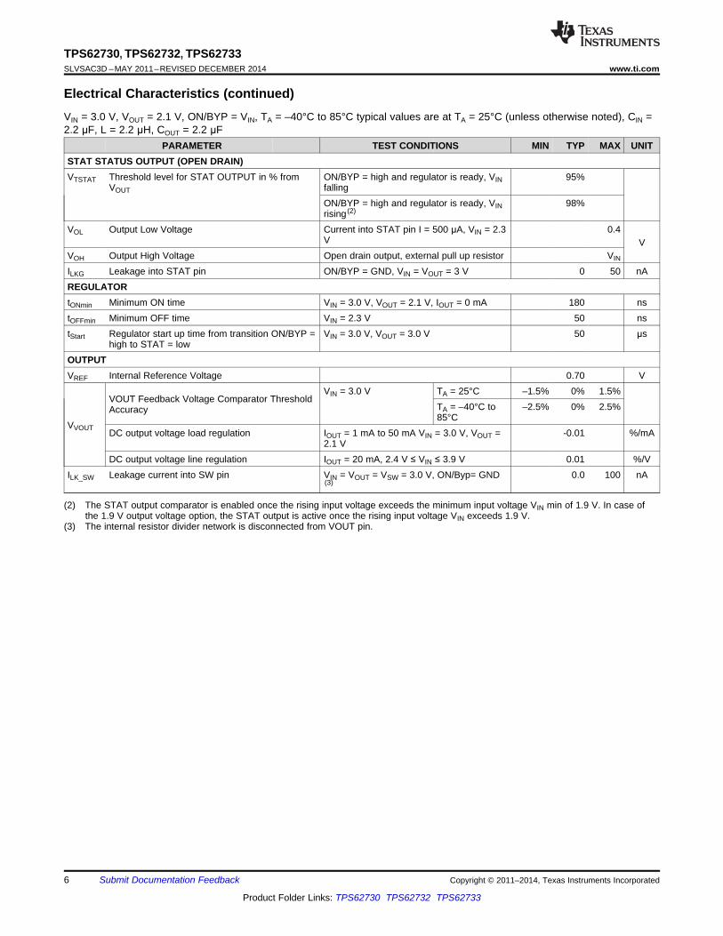
PARAMETER TEST CONDITIONS MIN TYP MAX UNITSTAT STATUS OUTPUT (OPEN DRAIN)VTSTAT Threshold level for STAT OUTPUT in % from ON/BYP = high and regulator is ready, VIN 95%
VOUT fallingON/BYP = high and regulator is ready, VIN 98%rising (2)
VOL Output Low Voltage Current into STAT pin I = 500 μA, VIN = 2.3 0.4V V
VOH Output High Voltage Open drain output, external pull up resistor VIN
ILKG Leakage into STAT pin ON/BYP = GND, VIN = VOUT = 3 V 0 50 nAREGULATORtONmin Minimum ON time VIN = 3.0 V, VOUT = 2.1 V, IOUT = 0 mA 180 nstOFFmin Minimum OFF time VIN = 2.3 V 50 nstStart Regulator start up time from transition ON/BYP = VIN = 3.0 V, VOUT = 3.0 V 50 μs
high to STAT = lowOUTPUTVREF Internal Reference Voltage 0.70 V
VIN = 3.0 V TA = 25°C –1.5% 0% 1.5%VOUT Feedback Voltage Comparator Threshold
TA = –40°C to –2.5% 0% 2.5%Accuracy85°C
VVOUT DC output voltage load regulation IOUT = 1 mA to 50 mA VIN = 3.0 V, VOUT = -0.01 %/mA2.1 V
DC output voltage line regulation IOUT = 20 mA, 2.4 V ≤ VIN ≤ 3.9 V 0.01 %/VILK_SW Leakage current into SW pin VIN = VOUT = VSW = 3.0 V, ON/Byp= GND 0.0 100 nA
(3)
(2) The STAT output comparator is enabled once the rising input voltage exceeds the minimum input voltage VIN min of 1.9 V. In case ofthe 1.9 V output voltage option, the STAT output is active once the rising input voltage VIN exceeds 1.9 V.
(3) The internal resistor divider network is disconnected from VOUT pin.
TPS62730, TPS62732, TPS62733SLVSAC3D –MAY 2011–REVISED DECEMBER 2014 www.ti.com
9 Detailed Description
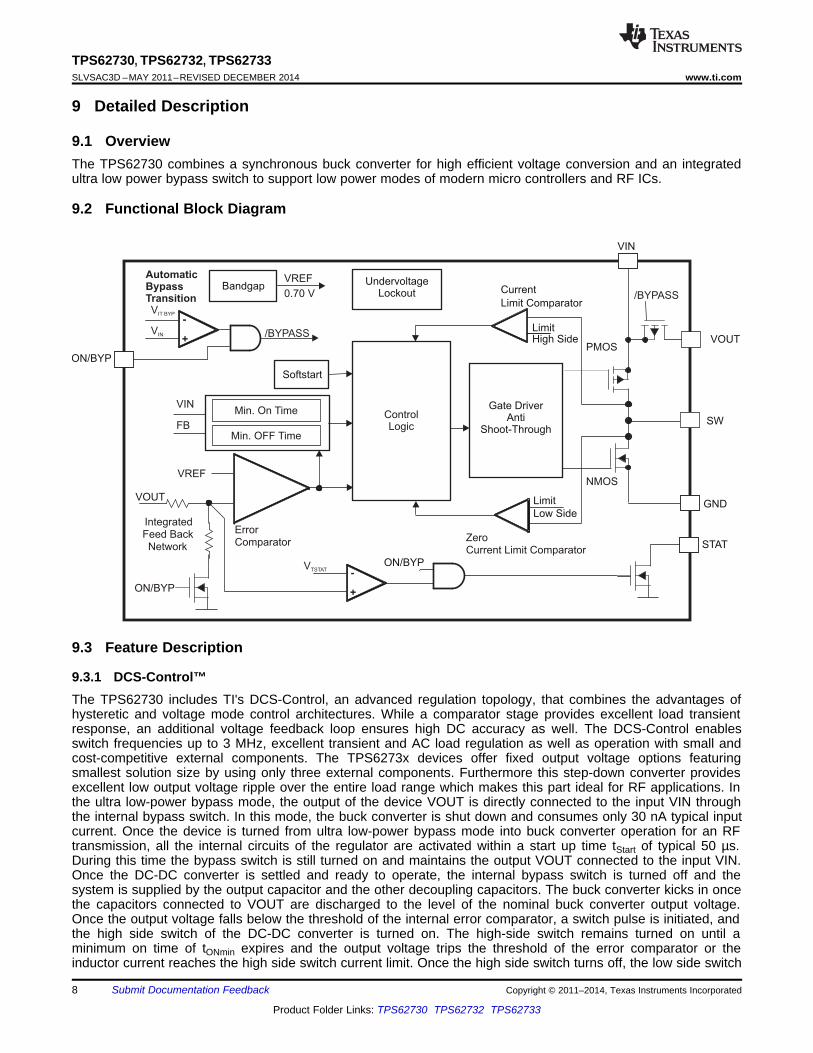
9.1 OverviewThe TPS62730 combines a synchronous buck converter for high efficient voltage conversion and an integratedultra low power bypass switch to support low power modes of modern micro controllers and RF ICs.
9.2 Functional Block Diagram
9.3 Feature Description
9.3.1 DCS-Control™The TPS62730 includes TI's DCS-Control, an advanced regulation topology, that combines the advantages ofhysteretic and voltage mode control architectures. While a comparator stage provides excellent load transientresponse, an additional voltage feedback loop ensures high DC accuracy as well. The DCS-Control enablesswitch frequencies up to 3 MHz, excellent transient and AC load regulation as well as operation with small andcost-competitive external components. The TPS6273x devices offer fixed output voltage options featuringsmallest solution size by using only three external components. Furthermore this step-down converter providesexcellent low output voltage ripple over the entire load range which makes this part ideal for RF applications. Inthe ultra low-power bypass mode, the output of the device VOUT is directly connected to the input VIN throughthe internal bypass switch. In this mode, the buck converter is shut down and consumes only 30 nA typical inputcurrent. Once the device is turned from ultra low-power bypass mode into buck converter operation for an RFtransmission, all the internal circuits of the regulator are activated within a start up time tStart of typical 50 µs.During this time the bypass switch is still turned on and maintains the output VOUT connected to the input VIN.Once the DC-DC converter is settled and ready to operate, the internal bypass switch is turned off and thesystem is supplied by the output capacitor and the other decoupling capacitors. The buck converter kicks in oncethe capacitors connected to VOUT are discharged to the level of the nominal buck converter output voltage.Once the output voltage falls below the threshold of the internal error comparator, a switch pulse is initiated, andthe high side switch of the DC-DC converter is turned on. The high-side switch remains turned on until aminimum on time of tONmin expires and the output voltage trips the threshold of the error comparator or theinductor current reaches the high side switch current limit. Once the high side switch turns off, the low side switch
TPS62730, TPS62732, TPS62733www.ti.com SLVSAC3D –MAY 2011–REVISED DECEMBER 2014
Feature Description (continued)rectifier is turned on and the inductor current ramps down until the high side switch turns on again or the inductorcurrent reaches zero. The converter operates in the PFM (pulse frequency modulation) mode during light loads,which maintains high efficiency over a wide load current range. In PFM mode, the device starts to skip switchpulses and generates only single pulses with the on time tONmin. The PFM mode of TPS62730 is optimized forlow output ripple voltage if small external components are used.
The on time tONmin can be estimated to:
where• tONmin: High side switch on time [ns]• VIN: Input voltage [V]• VOUT: Output voltage [V]• (1)
Therefore, the peak inductor current in PFM mode is approximately:
where• VIN: Input voltage [V]• VOUT: Output voltage [V]• L : Inductance [μH]• ILPFMpeak : PFM inductor peak current [mA] (2)
9.3.2 ON/BYP Mode SelectionThe DC-DC converter is activated when ON/BYP is set high. For proper operation, the ON/BYP pin must beterminated and may not be left floating. This pin is controlled by the RF transceiver or micro controller for propermode selection. Pulling the ON/BYP pin low activates the ultra low-power bypass mode with typical 30-nAcurrent consumption. In this mode, the internal bypass switch is turned on and the output of the DC-DC converteris connected to the battery VIN. All other circuits like the entire internal-control circuitry, the High Side and LowSide MOSFETs of the DC-DC output stage are turned off as well the internal resistor feedback divider isdisconnected. The ON/BYP must be controlled by a microcontroller for proper mode selection. In case ofCC2540, connect this to the power down signal which is output on one of the P1.x ports (see CC2540 userguide).
9.3.3 STAT Open-Drain OutputThe STAT output is active when the device is enabled (EN/BYP = high) and indicates the status of the outputvoltage. The STAT output is a open-drain output with active low level and needs a external pullup resistor toindicate a high level. It is driven by an internal comparator which monitors the output voltage VOUT. The STAT pinis tied to low level, if the output voltage VOUT is considered as valid and exceeding the threshold VTSTAT (95% ofVOUT for falling VIN and 98% of VOUT for rising VIN). The pin is high impedance with the ON/BYP pin set to lowlevel or VOUT is below the VTSTAT threshold. If not used, the STAT pin can be left open. See Figure 6 andFigure 7.
9.4.1 Start-UpOnce the device is supplied with a battery voltage, the bypass switch is activated. If the ON/BYP pin is set tohigh, the device operates in bypass mode until the DC-DC converter has settled and can kick in. During start-up,high peak currents can flow over the bypass switch to charge up the output capacitor and the additionaldecoupling capacitors in the system.
9.4.2 Automatic Transition from DC-DC to Bypass OperationWith the ON/BYP pin set to high, the TPS62730 is active and features an automatic transition between DC-DCand bypass mode to reduce the output ripple voltage to zero. Once the input voltage comes close to the outputvoltage of the DC-DC converter, the DC-DC converters operates close to 100% duty cycle operation. At thisoperating condition, the switch frequency would start to drop and would lead to increased output ripple voltage.The internal bypass switch is turned on once the battery voltage at VIN trips the Automatic Bypass TransitionThreshold VIT BYP for falling VIN. The DC-DC regulator is turned off and therefore it generates no output ripplevoltage. Due to the output is connected through the bypass switch to the input, the output voltage follows theinput voltage minus the voltage drop across the internal bypass switch. In this mode the current consumption ofthe DC-DC converter is reduced to typically 23 µA. Once the input voltage increases and trips the bypassdeactivation threshold VIT BYP for rising VIN, the DC-DC regulator turns on and the bypass switch is turned off.See Figure 7 and Figure 24.
9.4.3 Internal Current LimitThe TPS62730 integrates a High Side and Low Side MOSFET current limit to protect the device against heavyload or short circuit when the DC-DC converter is active. The current in the switches is monitored by current limitcomparators. When the current in the High Side MOSFET reaches its current limit, the High Side MOSFET isturned off and the Low Side MOSFET is turned on to ramp down the current in the inductor. The High SideMOSFET switch can only turn on again, once the current in the Low Side MOSFET switch has fallen below thethreshold of its current limit comparator. The bypass switch does not feature a current limit to support lowestcurrent consumption.
TPS62730, TPS62732, TPS62733www.ti.com SLVSAC3D –MAY 2011–REVISED DECEMBER 2014
10 Application and Implementation
NOTEInformation in the following applications sections is not part of the TI componentspecification, and TI does not warrant its accuracy or completeness. TI’s customers areresponsible for determining suitability of components for their purposes. Customers shouldvalidate and test their design implementation to confirm system functionality.
10.1 Application InformationThe TPS62730 is a high-frequency synchronous step down DC-DC converter optimized for ultra low-powerwireless applications. The device is optimized to supply TI's Low-Power Wireless sub 1-GHz and 2.4-GHz RFtransceivers and system-on-chip (SoC) solutions.
10.2 Typical Application
Figure 8. Typical Application
10.2.1 Design RequirementsThe TPS6273x is a highly integrated DC-DC converter. The output voltage is internally fixed and does not requireand external feedback divider network. For proper operation only a input- and output capacitor and an inductor isrequired. Table 1 shows the components used for the application characteristic curves.
Table 1. List of ComponentsREFERENCE DESCRIPTION VALUE MANUFACTURER DIMENSIONS
Step-down converter with bypassTPS62730 Texas Instruments 1.5 x 1.0 x 0.55 mmmodeCeramic capacitor 0402 X5R 6.3VCIN, COUT 2.2 µF Murata 1.0 x 0.5 x 0.5 mmGRM155R60J225
L Inductor MIPSZ2012 2R2 2.2 µH FDK 2.0 x 1.2 x 1.0 mm
10.2.2 Detailed Design Procedure
10.2.2.1 Output Filter Design (Inductor and Output Capacitor)The TPS62730 is optimized to operate with effective inductance values in the range of 1.5 μH to 3 μH and witheffective output capacitance in the range of 1.0 μF to 10 μF. The internal compensation is optimized to operatewith an output filter of L = 2.2 μH and COUT = 2.2 μF, which gives and LC output filter corner frequency of:
TPS62730, TPS62732, TPS62733SLVSAC3D –MAY 2011–REVISED DECEMBER 2014 www.ti.com
10.2.2.2 Inductor SelectionThe inductor value affects its peak-to-peak ripple current, the PWM-to-PFM transition point, the output voltageripple and the efficiency. The selected inductor must be rated for its DC resistance and saturation current. Theinductor ripple current (ΔIL) decreases with higher inductance and increases with higher VI N or VO UT. Equation 4calculates the maximum inductor current under static load conditions. The saturation current of the inductorshould be rated higher than the maximum inductor current as calculated with Equation 5.
where• f = Switching Frequency• L = Inductor Value• ΔIL= Peak-to-Peak inductor ripple current (4)
where• ΔIL= Peak-to-Peak inductor ripple current• ILmax = Maximum Inductor current (5)
In high-frequency converter applications, the efficiency is essentially affected by the inductor AC resistance (thatis, quality factor) and to a smaller extent by the inductor DCR value. To achieve high efficiency operation, careshould be taken in selecting inductors featuring a quality factor above 25 at the switching frequency. Increasingthe inductor value produces lower RMS currents, but degrades transient response. For a given physical inductorsize, increased inductance usually results in an inductor with lower saturation current.
The total losses of the coil consist of both the losses in the DC resistance, R(DC), and the following frequency-dependent components:• The losses in the core material (magnetic hysteresis loss, especially at high switching frequencies)• Additional losses in the conductor from the skin effect (current displacement at high frequencies)• Magnetic field losses of the neighboring windings (proximity effect)• Radiation losses
The following inductor series from different suppliers have been used with the TPS62730 converters.
Table 2. List of InductorsINDUCTANCE DIMENSIONS INDUCTOR TYPE SUPPLIER
10.2.2.3 DC-DC Output Capacitor SelectionThe DCS-Control scheme of the TPS62730 allows the use of tiny ceramic capacitors. Ceramic capacitors withlow ESR values have the lowest output voltage ripple and are recommended. The output capacitor requireseither an X7R or X5R dielectric. Y5V and Z5U dielectric capacitors, aside from their wide variation in capacitanceover temperature, become resistive at high frequencies. At light load currents the converter operate in powersave mode and the output voltage ripple is dependent on the output capacitor value and the PFM peak inductorcurrent.
10.2.2.4 Additional Decoupling CapacitorsIn addition to the output capacitor there are further decoupling capacitors connected to the output of theTPS62730. These decoupling capacitor are placed closely at the RF transmitter or micro controller. The totalcapacitance of these decoupling capacitors should be kept to a minimum and should not exceed the values givenin the reference designs, see Figure 31 and Figure 32. During mode transition from DC-DC operation to bypassmode the capacitors on the output VOUT are charged up to the battery voltage VIN through the internal bypass
TPS62730, TPS62732, TPS62733www.ti.com SLVSAC3D –MAY 2011–REVISED DECEMBER 2014
switch. During mode transition from bypass mode to DC-DC operation, these capacitors must be discharged bythe system supply current to the nominal output voltage threshold until the DC-DC converter will kick in. Thecharge change in the output and decoupling capacitors can be calculated according to Equation 6. The energyloss due to charge and discharge of the output and decoupling capacitors can be calculated according toEquation 7.
where• dQCOUT_CDEC : Charge change needed to charge up and discharge the output and decoupling capacitors from
VOUT_DC_DC to VIN and vice versa• CCOUT_CDEC: Total capacitance on the VOUT pin of the device, includes output and decoupling capacitors• VIN: Input (battery) voltage• VOUT_DC_DC: nominal DC-DC output voltage VOUT (6)
where• CCOUT_CDEC: Total capacitance on the VOUT pin of the device, includes output and decoupling capacitors• VIN: Input (battery) voltage• VOUT_DC_DC: nominal DC-DC output voltage VOUT (7)
10.2.2.5 Input Capacitor SelectionBecause of the nature of the buck converter having a pulsating input current, a low ESR input capacitor isrequired for best input voltage filtering to ensure proper function of the device and to minimize input voltagespikes. For most applications a 2.2 µF to 4.7 µF ceramic capacitor is recommended. The input capacitor can beincreased without any limit for better input voltage filtering.
Table 3 shows a list of tested input/output capacitors.
10.2.2.5.1 Input Buffer Capacitor Selection
In addition to the small ceramic input capacitor a larger buffer capacitor CBuf is recommended to reduce voltagedrops and ripple voltage. When using battery chemistries like Li-SOCl2, Li-SO2, Li-MnO2, the impedance of thebattery must be considered. These battery types tend to increase their impedance depending on dischargestatus and often can support output currents of only a few mA. Therefore a buffer capacitor is recommended tostabilize the battery voltage during DC-DC operations (for example, for an RF transmission). A voltage drop onthe input of the TPS62730 during DC-DC operation impacts the advantage of the step-down conversion forsystem power reduction. Furthermore the voltage drops can fall below the minimum recommended operatingvoltage of the device and leads to an early system cut off. Both impacts effects reduce the battery life time. Toachieve best performance and to extract most energy out of the battery, a good procedure is to design the selectthe buffer capacitor value for an voltage drop below 50 mVpp during DC-DC operation. The capacitor valuestrongly depends on the used battery type, as well the current consumption during an RF transmission as wellthe duration of the transmission.
Table 3. List of CapacitorCAPACITANCE [μF] SIZE CAPACITOR TYPE SUPPLIER
2.2 0402 GRM155R60J225 Murata
10.2.2.6 Checking Loop StabilityThe first step of circuit and stability evaluation is to look from a steady-state perspective at the following signals:• Switching node, SW• Inductor current, IL• Output ripple voltage, VOUT(AC)
Basic signals must be measured when evaluating a switching converter. When the switching waveform showslarge duty cycle jitter or the output voltage or inductor current shows oscillations, the regulation loop may beunstable. This is often a result of board layout and/or L-C combination.
TPS62730, TPS62732, TPS62733SLVSAC3D –MAY 2011–REVISED DECEMBER 2014 www.ti.com
As a next step in the evaluation of the regulation loop, the load transient response is tested. The time betweenthe application of the load transient and the turn on of the High Side MOSFET, the output capacitor must supplyall of the current required by the load. VOUT immediately shifts by an amount equal to ΔI(LOAD) x ESR, where ESRis the effective series resistance of COUT. ΔI(LOAD) begins to charge or discharge CO generating a feedback errorsignal used by the regulator to return VOUT to its steady-state value. The results are most easily interpreted whenthe device operates in PWM mode.
During this recovery time, VOUT can be monitored for settling time, overshoot or ringing that helps judge theconverter’s stability. Without any ringing, the loop has usually more than 45° of phase margin.
Because the damping factor of the circuitry is directly related to several resistive parameters (for example,MOSFET rDS(on)) that are temperature dependant, the loop stability analysis must be done over the input voltagerange, load current range, and temperature range.
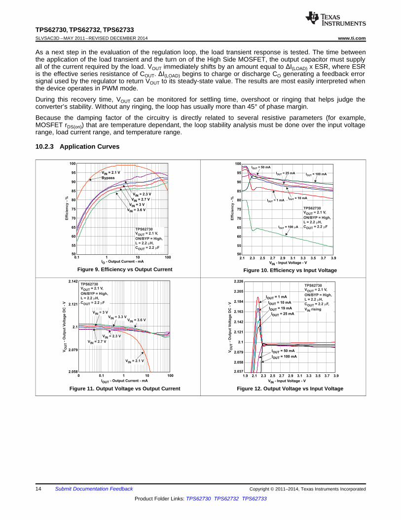
10.2.3 Application Curves
Figure 9. Efficiency vs Output Current Figure 10. Efficiency vs Input Voltage
Figure 11. Output Voltage vs Output Current Figure 12. Output Voltage vs Input Voltage
TPS62730, TPS62732, TPS62733www.ti.com SLVSAC3D –MAY 2011–REVISED DECEMBER 2014
11 Power Supply RecommendationsThe power supply to the TPS62730 must have a current rating according to the supply voltage, output voltageand output current of the TPS62730.
12 Layout
12.1 Layout GuidelinesAs for all switching power supplies, the layout is an important step in the design. Especially RF designs demandcareful attention to the PCB layout. Care must be taken in board layout to get the specified performance. If thelayout is not carefully done, the regulator could show poor line and/or load regulation, stability issues as well asEMI problems and interference with RF circuits. It is critical to provide a low inductance, impedance ground path.Therefore, use wide and short traces for the main current paths. The input capacitor should be placed as closeas possible to the IC pins as well as the inductor and output capacitor. Use a common Power GND node and adifferent node for the Signal GND to minimize the effects of ground noise. Keep the common path to the GNDPIN, which returns the small signal components and the high current of the output capacitors as short aspossible to avoid ground noise. The VOUT line should be connected to the output capacitor and routed awayfrom noisy components and traces (for example, SW line).
TPS62730, TPS62732, TPS62733SLVSAC3D –MAY 2011–REVISED DECEMBER 2014 www.ti.com
13 Device and Documentation Support
13.1 Device Support
13.1.1 Third-Party Products DisclaimerTI'S PUBLICATION OF INFORMATION REGARDING THIRD-PARTY PRODUCTS OR SERVICES DOES NOTCONSTITUTE AN ENDORSEMENT REGARDING THE SUITABILITY OF SUCH PRODUCTS OR SERVICESOR A WARRANTY, REPRESENTATION OR ENDORSEMENT OF SUCH PRODUCTS OR SERVICES, EITHERALONE OR IN COMBINATION WITH ANY TI PRODUCT OR SERVICE.
13.2 Related LinksThe table below lists quick access links. Categories include technical documents, support and communityresources, tools and software, and quick access to sample or buy.
Table 4. Related LinksTECHNICAL TOOLS & SUPPORT &PARTS PRODUCT FOLDER SAMPLE & BUY DOCUMENTS SOFTWARE COMMUNITY
TPS62730 Click here Click here Click here Click here Click hereTPS62732 Click here Click here Click here Click here Click hereTPS62733 Click here Click here Click here Click here Click here
13.3 TrademarksBluetooth is a trademark of Bluetooth SIG.All other trademarks are the property of their respective owners.
13.4 Electrostatic Discharge CautionThese devices have limited built-in ESD protection. The leads should be shorted together or the device placed in conductive foamduring storage or handling to prevent electrostatic damage to the MOS gates.
13.5 GlossarySLYZ022 — TI Glossary.
This glossary lists and explains terms, acronyms, and definitions.
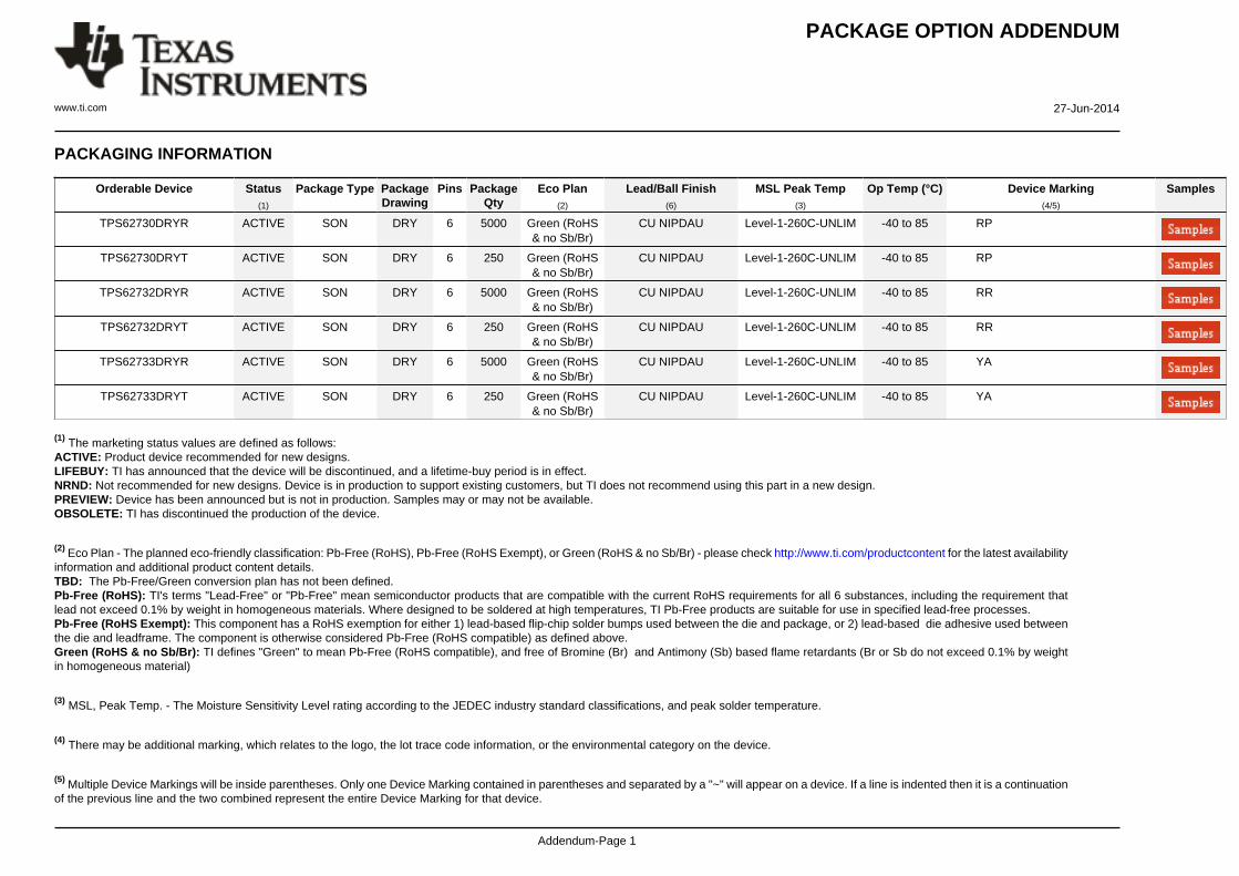
14 Mechanical, Packaging, and Orderable InformationThe following pages include mechanical, packaging, and orderable information. This information is the mostcurrent data available for the designated devices. This data is subject to change without notice and revision ofthis document. For browser-based versions of this data sheet, refer to the left-hand navigation.
TPS62730DRYR ACTIVE SON DRY 6 5000 Green (RoHS& no Sb/Br)
CU NIPDAU Level-1-260C-UNLIM -40 to 85 RP
TPS62730DRYT ACTIVE SON DRY 6 250 Green (RoHS& no Sb/Br)
CU NIPDAU Level-1-260C-UNLIM -40 to 85 RP
TPS62732DRYR ACTIVE SON DRY 6 5000 Green (RoHS& no Sb/Br)
CU NIPDAU Level-1-260C-UNLIM -40 to 85 RR
TPS62732DRYT ACTIVE SON DRY 6 250 Green (RoHS& no Sb/Br)
CU NIPDAU Level-1-260C-UNLIM -40 to 85 RR
TPS62733DRYR ACTIVE SON DRY 6 5000 Green (RoHS& no Sb/Br)
CU NIPDAU Level-1-260C-UNLIM -40 to 85 YA
TPS62733DRYT ACTIVE SON DRY 6 250 Green (RoHS& no Sb/Br)
CU NIPDAU Level-1-260C-UNLIM -40 to 85 YA
(1) The marketing status values are defined as follows:ACTIVE: Product device recommended for new designs.LIFEBUY: TI has announced that the device will be discontinued, and a lifetime-buy period is in effect.NRND: Not recommended for new designs. Device is in production to support existing customers, but TI does not recommend using this part in a new design.PREVIEW: Device has been announced but is not in production. Samples may or may not be available.OBSOLETE: TI has discontinued the production of the device.
(2) Eco Plan - The planned eco-friendly classification: Pb-Free (RoHS), Pb-Free (RoHS Exempt), or Green (RoHS & no Sb/Br) - please check http://www.ti.com/productcontent for the latest availabilityinformation and additional product content details.TBD: The Pb-Free/Green conversion plan has not been defined.Pb-Free (RoHS): TI's terms "Lead-Free" or "Pb-Free" mean semiconductor products that are compatible with the current RoHS requirements for all 6 substances, including the requirement thatlead not exceed 0.1% by weight in homogeneous materials. Where designed to be soldered at high temperatures, TI Pb-Free products are suitable for use in specified lead-free processes.Pb-Free (RoHS Exempt): This component has a RoHS exemption for either 1) lead-based flip-chip solder bumps used between the die and package, or 2) lead-based die adhesive used betweenthe die and leadframe. The component is otherwise considered Pb-Free (RoHS compatible) as defined above.Green (RoHS & no Sb/Br): TI defines "Green" to mean Pb-Free (RoHS compatible), and free of Bromine (Br) and Antimony (Sb) based flame retardants (Br or Sb do not exceed 0.1% by weightin homogeneous material)
(3) MSL, Peak Temp. - The Moisture Sensitivity Level rating according to the JEDEC industry standard classifications, and peak solder temperature.
(4) There may be additional marking, which relates to the logo, the lot trace code information, or the environmental category on the device.
(5) Multiple Device Markings will be inside parentheses. Only one Device Marking contained in parentheses and separated by a "~" will appear on a device. If a line is indented then it is a continuationof the previous line and the two combined represent the entire Device Marking for that device.
(6) Lead/Ball Finish - Orderable Devices may have multiple material finish options. Finish options are separated by a vertical ruled line. Lead/Ball Finish values may wrap to two lines if the finishvalue exceeds the maximum column width.
Important Information and Disclaimer:The information provided on this page represents TI's knowledge and belief as of the date that it is provided. TI bases its knowledge and belief on informationprovided by third parties, and makes no representation or warranty as to the accuracy of such information. Efforts are underway to better integrate information from third parties. TI has taken andcontinues to take reasonable steps to provide representative and accurate information but may not have conducted destructive testing or chemical analysis on incoming materials and chemicals.TI and TI suppliers consider certain information to be proprietary, and thus CAS numbers and other limited information may not be available for release.
In no event shall TI's liability arising out of such information exceed the total purchase price of the TI part(s) at issue in this document sold by TI to Customer on an annual basis.
IMPORTANT NOTICETexas Instruments Incorporated and its subsidiaries (TI) reserve the right to make corrections, enhancements, improvements and otherchanges to its semiconductor products and services per JESD46, latest issue, and to discontinue any product or service per JESD48, latestissue. Buyers should obtain the latest relevant information before placing orders and should verify that such information is current andcomplete. All semiconductor products (also referred to herein as “components”) are sold subject to TI’s terms and conditions of salesupplied at the time of order acknowledgment.TI warrants performance of its components to the specifications applicable at the time of sale, in accordance with the warranty in TI’s termsand conditions of sale of semiconductor products. Testing and other quality control techniques are used to the extent TI deems necessaryto support this warranty. Except where mandated by applicable law, testing of all parameters of each component is not necessarilyperformed.TI assumes no liability for applications assistance or the design of Buyers’ products. Buyers are responsible for their products andapplications using TI components. To minimize the risks associated with Buyers’ products and applications, Buyers should provideadequate design and operating safeguards.TI does not warrant or represent that any license, either express or implied, is granted under any patent right, copyright, mask work right, orother intellectual property right relating to any combination, machine, or process in which TI components or services are used. Informationpublished by TI regarding third-party products or services does not constitute a license to use such products or services or a warranty orendorsement thereof. Use of such information may require a license from a third party under the patents or other intellectual property of thethird party, or a license from TI under the patents or other intellectual property of TI.Reproduction of significant portions of TI information in TI data books or data sheets is permissible only if reproduction is without alterationand is accompanied by all associated warranties, conditions, limitations, and notices. TI is not responsible or liable for such altereddocumentation. Information of third parties may be subject to additional restrictions.Resale of TI components or services with statements different from or beyond the parameters stated by TI for that component or servicevoids all express and any implied warranties for the associated TI component or service and is an unfair and deceptive business practice.TI is not responsible or liable for any such statements.Buyer acknowledges and agrees that it is solely responsible for compliance with all legal, regulatory and safety-related requirementsconcerning its products, and any use of TI components in its applications, notwithstanding any applications-related information or supportthat may be provided by TI. Buyer represents and agrees that it has all the necessary expertise to create and implement safeguards whichanticipate dangerous consequences of failures, monitor failures and their consequences, lessen the likelihood of failures that might causeharm and take appropriate remedial actions. Buyer will fully indemnify TI and its representatives against any damages arising out of the useof any TI components in safety-critical applications.In some cases, TI components may be promoted specifically to facilitate safety-related applications. With such components, TI’s goal is tohelp enable customers to design and create their own end-product solutions that meet applicable functional safety standards andrequirements. Nonetheless, such components are subject to these terms.No TI components are authorized for use in FDA Class III (or similar life-critical medical equipment) unless authorized officers of the partieshave executed a special agreement specifically governing such use.Only those TI components which TI has specifically designated as military grade or “enhanced plastic” are designed and intended for use inmilitary/aerospace applications or environments. Buyer acknowledges and agrees that any military or aerospace use of TI componentswhich have not been so designated is solely at the Buyer's risk, and that Buyer is solely responsible for compliance with all legal andregulatory requirements in connection with such use.TI has specifically designated certain components as meeting ISO/TS16949 requirements, mainly for automotive use. In any case of use ofnon-designated products, TI will not be responsible for any failure to meet ISO/TS16949.Products ApplicationsAudio www.ti.com/audio Automotive and Transportation www.ti.com/automotiveAmplifiers amplifier.ti.com Communications and Telecom www.ti.com/communicationsData Converters dataconverter.ti.com Computers and Peripherals www.ti.com/computersDLP® Products www.dlp.com Consumer Electronics www.ti.com/consumer-appsDSP dsp.ti.com Energy and Lighting www.ti.com/energyClocks and Timers www.ti.com/clocks Industrial www.ti.com/industrialInterface interface.ti.com Medical www.ti.com/medicalLogic logic.ti.com Security www.ti.com/securityPower Mgmt power.ti.com Space, Avionics and Defense www.ti.com/space-avionics-defenseMicrocontrollers microcontroller.ti.com Video and Imaging www.ti.com/videoRFID www.ti-rfid.comOMAP Applications Processors www.ti.com/omap TI E2E Community e2e.ti.comWireless Connectivity www.ti.com/wirelessconnectivity


![Modeling Power in Electric Vehicles - Department of ...web.eecs.utk.edu/~dcostine/ECE620/Fall2014/lectures/EVSeminar.pdf · 0.5 1 1.5 2 2.5 3 Bypass Converter Losses [W] Bypass Converter](https://static.documents.pub/doc/80x56/5c0974ef09d3f24b368b8600/modeling-power-in-electric-vehicles-department-of-webeecsutkedudcostineece620fall2014lectures.jpg)


