19
Lars Kirchner Linde Engineering Pullach, May 2009 CCT 2009 Presentation Stepwise Extension of a Gas Cleanup for IGCC Application

Lars KirchnerLinde EngineeringPullach, May 2009
CCT 2009 PresentationStepwise Extension of a Gas Cleanup for IGCC Application

Linde AG Engineering Division 2
CO2-Concentration in the atmosphere since the industrialisation

Linde AG Engineering Division 3
Power Generation and CO2 Sequestration – Post Combustion Capture(Linde’s involvement)
Power Plant Scenarios with CO2 Sequestration— Post Combustion Capture
— Oxyfuel Technology
— Precombustion Capture and Integrated Gasification Combined Cycle (IGCC)
CO2 Rich Flue Gas
Virtually CO2 Free Flue GasCO2 to Sequestration
— Relatively minor modifications to conventional technology.
— Linde is involved in extensive R&D work.
Air
Feedstock
SteamCombustion&
Steam Generation
Power Generation&
Heat Recovery
Scrubbing System
Linde Portfolio
Linde AG Engineering Division 4
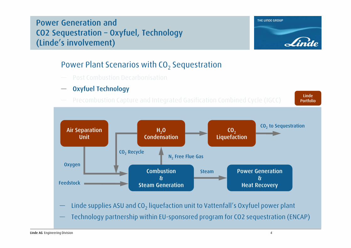
Power Generation and CO2 Sequestration – Oxyfuel, Technology(Linde’s involvement)
CO2 Rich Flue Gas
Virtually CO2 Free Flue GasCO2 to Sequestration
— Relatively minor modifications to conventional technology.
— Linde is involved in extensive R&D work.
Air
Feedstock
SteamCombustion&
Steam Generation
Power Generation&
Heat Recovery
Scrubbing System
N2 Free Flue Gas
CO2 to Sequestration
— Linde supplies ASU and CO2 liquefaction unit to Vattenfall’s Oxyfuel power plant
— Technology partnership within EU-sponsored program for CO2 sequestration (ENCAP)
Oxygen
Feedstock
SteamCombustion&
Steam Generation
Power Generation&
Heat Recovery
H2O Condensation
CO2 Liquefaction
CO2 Recycle
Air Separation Unit
Power Plant Scenarios with CO2 Sequestration— Post Combustion Decarbonisation
— Oxyfuel Technology
— Precombustion Capture and Integrated Gasification Combined Cycle (IGCC)Linde
Portfolio

Linde AG Engineering Division 5
Power Generation and CO2 Sequestration – Precombustion Capture
N2 Free Flue Gas
CO2 to Sequestration
— Linde supplies ASU and CO2 liquefaction unit to Vattenfall’s Oxyfuel power plant
— Technology partnership within EU-sponsored program for CO2 sequestration (ENCAP)
Oxygen
Feedstock
SteamCombustion&
Steam Generation
Power Generation&
Heat Recovery
H2O Condensation
C2O Liquefaction
CO2 Recycle
Air Separation Unit
Raw Synthesis Gas
CO2 to Sequestration
— Linde provides all technologies within gasification island & syngas conditioning
— Linde is involved in various IGCC projects including CO2 sequestration
Oxygen
FeedstockGasification
Power Generation&
Heat Recovery
Shift C02 RecoveryAir Separation Unit
Conditioned Synthesis Gas
Power Plant Scenarios with CO2 Sequestration— Post Combustion Decarbonisation
— Oxyfuel Technology
— Precombustion Capture and Integrated Gasification Combined Cycle (IGCC)Linde
Portfolio

Linde AG Engineering Division 6
Block Flow Diagram Syngas Generation for IGCC Plant
Sulfur
AirSeparation
AirSeparation
GasificationGasification HeatRecovery
HeatRecovery
Sulphur & CO2Removal
SulphurRecoverySulphur
Recovery
HPOxygen
Syngas
Super-heaterSuper-heater
Air
Slag
Coal/Coke
COShift
Tail Gas
Superheated Steam
Steam
Steam
Steam
Nitrogen
CO2Compression
to Sequestration
Compressor

Linde AG Engineering Division 7
General Information about the Rectisol® Process
Linde’s Rectisol® Wash ProcessLinde’s Rectisol® Wash Unit in Jilin, China

Linde AG Engineering Division 8
Linde’s Rectisol® Installations
50 References worldwide21 New contracts since 2003

Linde AG Engineering Division 9
What is Rectisol®?
→ Rectisol® was developed jointly by Linde and Lurgi in the late 50th
and has been improved ever since
→ Rectisol® is a physical wash process where acid gas compounds
are dissolved in methanol
→ Linde owns and operates 3 plants (Singapore and
the United States)
→ Each Rectisol® Wash Unit is individually designed according to customer’s
needs and requirements
→ Handling always requires site specific adaptation
Methanol Molecule
Characteristics of Rectisol®

Linde AG Engineering Division 10
Trace Component Handling in Rectisol®
Main Components in the Feedgas→ H2→ CO
Acid Components in the Feedgas
→ CO2→ H2S→ COS
Impurities in the Feedgas
→ HCN→ NH3→ Metal Carbonyls
→ H2O
⇒ Shall remain in the Feedgas
⇒ To be removed within the Process
⇒ Can be handled safelyby Rectisol®
Linde AG Engineering Division 11
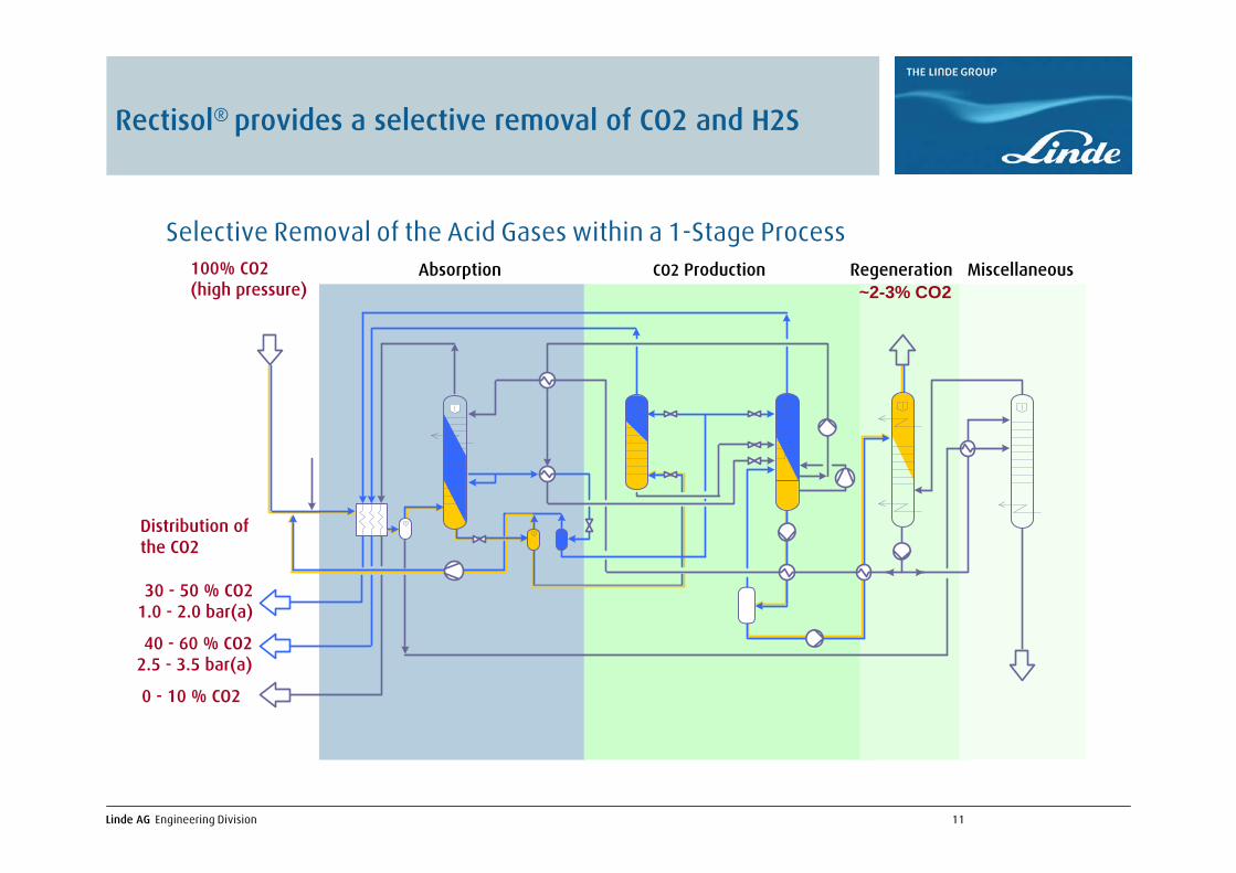
Rectisol® provides a selective removal of CO2 and H2S
Selective Removal of the Acid Gases within a 1-Stage ProcessAbsorption CO2 Production Regeneration Miscellaneous100% CO2
(high pressure)
0 - 10 % CO2
40 - 60 % CO22.5 - 3.5 bar(a)
30 - 50 % CO21.0 - 2.0 bar(a)
~2-3% CO2
Distribution of the CO2
Linde AG Engineering Division 12
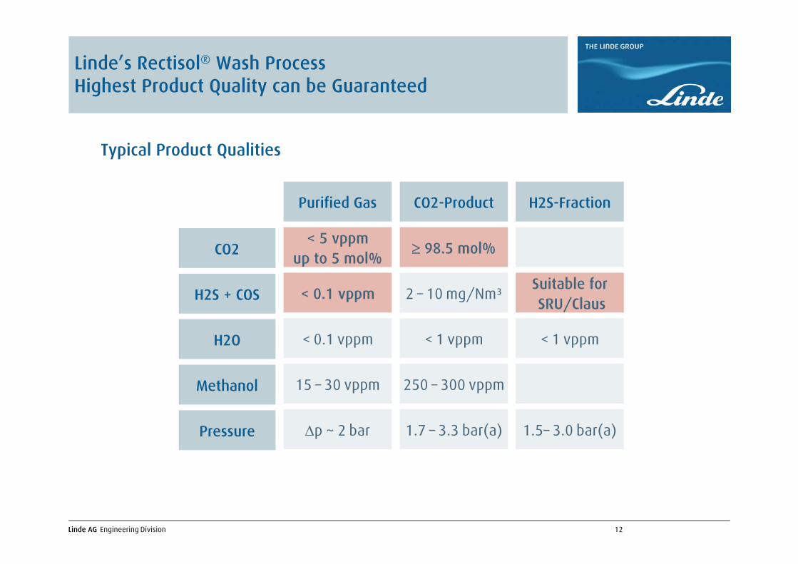
≥ 98.5 mol%
Suitable forSRU/Claus
< 1 vppm
1.5– 3.0 bar(a)
< 1 vppm
250 – 300 vppm
1.7 – 3.3 bar(a)
2 – 10 mg/Nm³
Purified Gas CO2-Product H2S-Fraction
CO2
H2S + COS
H2O
Methanol
Pressure
< 5 vppmup to 5 mol%
< 0.1 vppm
< 0.1 vppm
15 – 30 vppm
Δp ~ 2 bar
Typical Product Qualities
Linde’s Rectisol® Wash ProcessHighest Product Quality can be Guaranteed

Linde AG Engineering Division 13
→ Process and apparatus to achieve high H2S enrichment→ Process and apparatus to handle carbonyl loaded methanol→ Process and apparatus to increase of the CO2 product recovery→ Process and apparatus for usage of a semi-lean Solvent for 1-stage selective
CO2 Removal→ Apparatus to reduce the column height
Despite Rectisol® is already a mature and proven process, Linde is still improving itThe most recently filed patents are:
Linde’s Technology Improvements of the Rectisol® Process
Linde had more than 20 Rectisol® projects in the last three years and higher product purity requirements combined with lower quality feeds drove theinnovation process
Linde AG Engineering Division 14
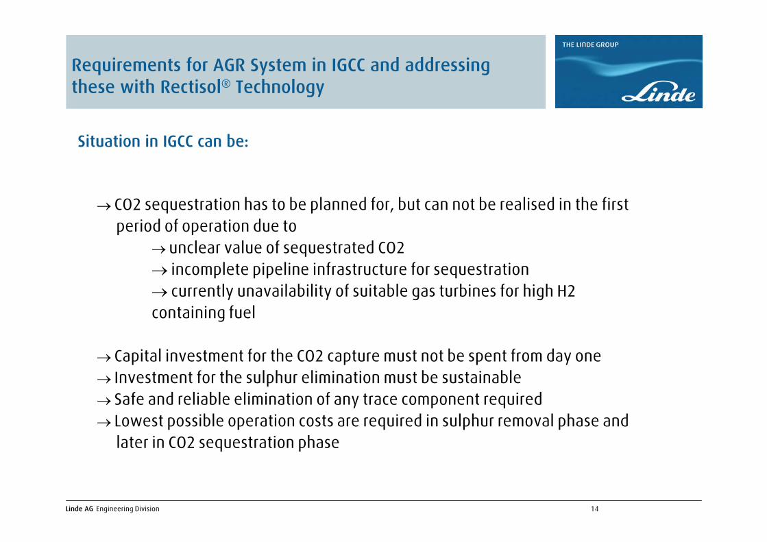
→ CO2 sequestration has to be planned for, but can not be realised in the first period of operation due to
→ unclear value of sequestrated CO2→ incomplete pipeline infrastructure for sequestration→ currently unavailability of suitable gas turbines for high H2 containing fuel
→ Capital investment for the CO2 capture must not be spent from day one→ Investment for the sulphur elimination must be sustainable→ Safe and reliable elimination of any trace component required→ Lowest possible operation costs are required in sulphur removal phase and
later in CO2 sequestration phase
Situation in IGCC can be:
Requirements for AGR System in IGCC and addressing these with Rectisol® Technology
Linde AG Engineering Division 15
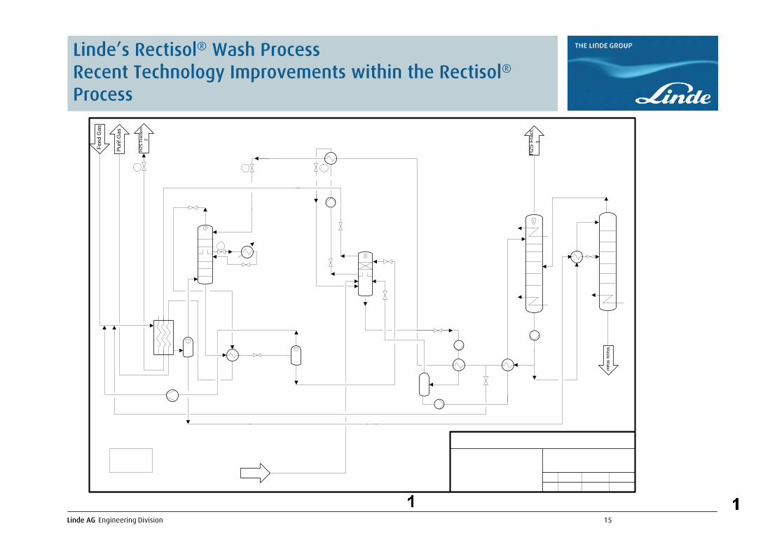
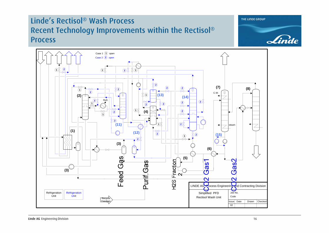
Linde’s Rectisol® Wash ProcessRecent Technology Improvements within the Rectisol®Process
Waste W
ater
H2S
Fra
ct.
1
Pur
if.G
as
Feed
Gas
H2S
Fra
ctio
n2
Linde AG Engineering Division 16
Linde’s Rectisol® Wash ProcessRecent Technology Improvements within the Rectisol®Process
steam
C.W.
Refr.
(1)
LINDE AG Process Engineering and Contracting Division
Simplified PFD Job No.Code
Issue Date Drawn Checked
Rectisol Wash Unit
02
(7)1
Case 1 1 open
2 openCase 2
1
2
2
2
21
1
2
1
1
2
2
2
(2)
(3)
(4)
(5)
(6)
(8)
(11)
RecycleFeedgas
2
1
2
2
1
2
2
2
2
2
1
21
2
2
(3)
(12)
(13)
(15)
(14)
RefrigerationUnit
RefrigerationUnit
Linde AG Engineering Division 17
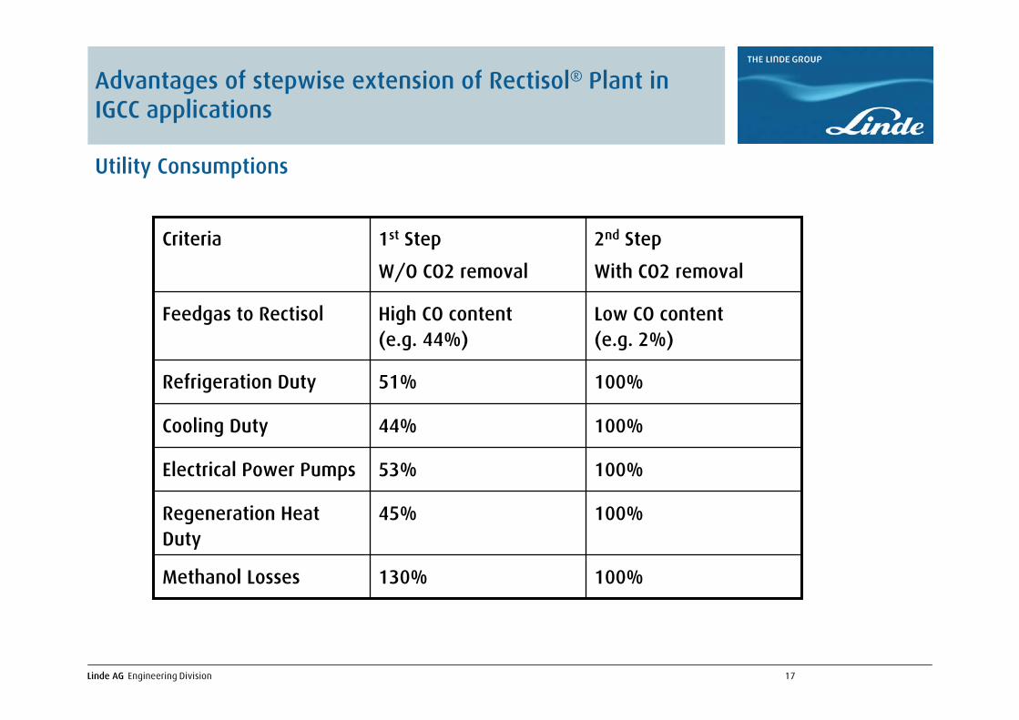
Advantages of stepwise extension of Rectisol® Plant in IGCC applications
Utility Consumptions
100%130%Methanol Losses
100%45%Regeneration Heat Duty
100%53%Electrical Power Pumps
100%44%Cooling Duty
100%51%Refrigeration Duty
Low CO content(e.g. 2%)
High CO content(e.g. 44%)
Feedgas to Rectisol
2nd Step
With CO2 removal
1st Step
W/O CO2 removal
Criteria

Linde AG Engineering Division 18
Advantages of stepwise extension of Rectisol® Plant in IGCC applications
Invest Cost Comparison
100%70%Construction Cost
100%75%Total installed Cost
100%70%Bulk Material Cost
100%76%Equipment Cost
2nd Step
With CO2 removal
1st Step
W/O CO2 removal
Criteria

Linde AG Engineering Division 19
Thank you for your attention
Chinese stamp showing Rectisol® and Nitrogen Wash Unit in Urumuqi


