65
Stereo and Multiview Yao Wang Polytechnic School of Engineering, New York University © Yao Wang, 2015 EL-GY 6123: Image and Video Processing 1
Stereo and Multiview
Yao Wang Polytechnic School of Engineering, New York University
© Yao Wang, 2015 EL-GY 6123: Image and Video Processing 1

© Yao Wang, 2015 EL-GY 6123: Image and Video Processing 2
Outline
• Depth perception • Depth from disparity • Depth sensors • View synthesis • Stereo and multiview video display • Stereo and multiview video compression
– MPEG2 multiview – H264 multiview coding (MVC) extension – HEVC multiview video + depth (MVD) extension
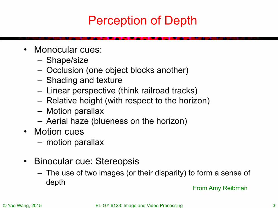
Perception of Depth
• Monocular cues: – Shape/size – Occlusion (one object blocks another) – Shading and texture – Linear perspective (think railroad tracks) – Relative height (with respect to the horizon) – Motion parallax – Aerial haze (blueness on the horizon)
• Motion cues – motion parallax
• Binocular cue: Stereopsis – The use of two images (or their disparity) to form a sense of
depth
© Yao Wang, 2015 EL-GY 6123: Image and Video Processing 3
From Amy Reibman

© Yao Wang, 2015 EL-GY 6123: Image and Video Processing 4
Depth Perception by Stereopsis
• Human eye perceives depth by having two eyes with slightly shifted views – The shift is called “disparity” – Perceived depth depends on the the “disparity” – Such depth perception is called “stereopsis”…

© Yao Wang, 2015 EL-GY 6123: Image and Video Processing 5
A Visual Experiment
Try to look at the left and right images using your left and right eyes separately while try to merge the two images into one. Can you tell which ball is closer?
Pictures generated by ray-tracing. Courtesy of Rushang Wang
How do we deduce depth from stereo views?
• Depth from disparity
© Yao Wang, 2015 EL-GY 6123: Image and Video Processing 6
© Yao Wang, 2015 EL-GY 6123: Image and Video Processing 7
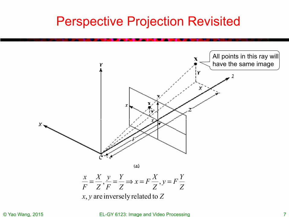
Perspective Projection Revisited
ZyxZYFy
ZXFx
ZY
Fy
ZX
Fx
torelatedinversely are ,
,, ==⇒==
All points in this ray will have the same image

© Yao Wang, 2015 EL-GY 6123: Image and Video Processing 8
Parallel Camera Configuration
i) Only horizontal disparity ii) Disparity is inversely proportional to Z iii) Range of disparity increases with B

Disparity and Depth
© Yao Wang, 2015 EL-GY 6123: Image and Video Processing 9
Negative disparity: Object in front of the screen
Positive disparity Object behind the screen
From Amy Reibman
© Yao Wang, 2015 EL-GY 6123: Image and Video Processing 10
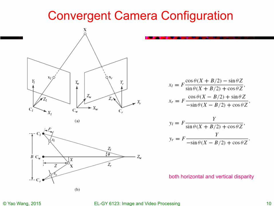
Convergent Camera Configuration
• See text
both horizontal and vertical disparity

© Yao Wang, 2015 EL-GY 6123: Image and Video Processing 11
Example Images (Converging Camera)
Notice the keystone effect Can get a better depth perception of objects closer to the camera than with the parallel set up But when displayed using a parallel projection system and viewed by the human eye, the vertical disparity causes perceptual discomfort. Geometric correction is needed before displaying these images.
© Yao Wang, 2015 EL-GY 6123: Image and Video Processing 12
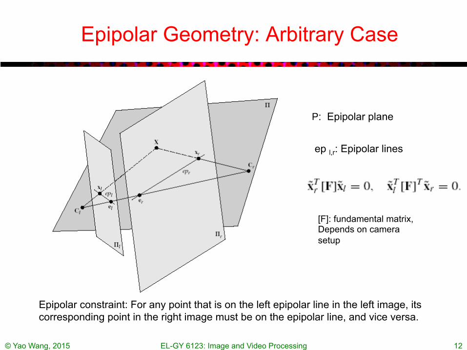
Epipolar Geometry: Arbitrary Case
P: Epipolar plane
ep l,r: Epipolar lines
Epipolar constraint: For any point that is on the left epipolar line in the left image, its corresponding point in the right image must be on the epipolar line, and vice versa.
[F]: fundamental matrix, Depends on camera setup

© Yao Wang, 2015 EL-GY 6123: Image and Video Processing 13
Epipolar Geometry: Parallel Case
• Epipolar constraint: the corresponding left and right image points should be on the same horizontal line (only horizontal disparity exists)
Rectification: creation of images as if acquired from parallel cameras

© Yao Wang, 2015 EL-GY 6123: Image and Video Processing 14
Disparity Estimation
• Disparity Estimation Problem: – For each point in one (anchor) image, find its corresponding point in the other
(target) image – Similar to motion estimation problem – Parallel configuration: only horizontal disparity needs to be estimated. – Difficulty: disparity range may be very large for objects nearby (up to 40-50
pixels); occlusion areas are prevalent (area appearing only in one view); depth discontinuity are prevalent (must apply smoothness criterion judiciously!); intensity matching does not work in flat surface area.
• Constraints for disparity estimation • Dense disparity estimation • Block-based disparity estimation • Mesh-based disparity estimation • Line-by-line estimation using dynamic programing • 3D structure estimation
© Yao Wang, 2015 EL-GY 6123: Image and Video Processing 15
Constraints for Disparity Estimation
• Epipolar constraints: – For parallel set up: two corresponding points are in the same
line, only horizontal disparity need to be searched – For an arbitrary camera set up: given x_r, possible x_l sits on a
line (epipolar line)
• Ordering constrain (for points at the same depth)t: – If two points in the right image are such that – Then the corresponding two points in the left image satisfy
• Models for disparity functions

© Yao Wang, 2015 EL-GY 6123: Image and Video Processing 16
Models for Disparity Functions
• Affine model for plane surface, parallel set-up: – If an imaged object has a plane surface
then the disparity function for points on the surface satisfies affine model:
(Proof: HW!) • For an arbitrary scene, we can divide the reference (right) image
into small blocks so that the object surface corresponding to each block is approximately flat. Then the disparity function over each block can be modeled as affine.
• Using similar approach, can derive models for curved surfaces (higher order polynomial)
© Yao Wang, 2015 EL-GY 6123: Image and Video Processing 17
Block-Based Disparity Estimation
• Following the method for block-based motion estimation – Divide the anchor image (e.g. right image) into regular blocks – Assume disparity function over each block is constant or an
affine function – Determine the constant or the affine parameters – For parallel set up: Only1 horizontal disparity or 3 affine
parameters
• Difference from motion estimation – Constant disparity model is less effective than constant motion
model even over small blocks – Affine model is quite good – Need a large search range to account for disparities in objects
nearby – Occlusion is more prevalent and need to be handled effectively

Dense Disparity Estimation
• Estimate the disparity at every pixel • Can be solved by using block-based approach by
putting a block surrounding each pixel
© Yao Wang, 2015 EL-GY 6123: Image and Video Processing 18

Challenges of disparity estimation
© Yao Wang, 2015 EL-GY 6123: Image and Video Processing 19
Ground truth depth image
White: flat texture Black: occluded region in another view
White: depth discontinuity region Black: occluded region in another view

Imposing constraints between estimated disparity in adjacent blocks/pixels
• Independent estimation at each block/pixel may lead to conflicting estimates
• Smoothness constraint: similar to motion estimation, may add a penalty term to the cost function to discourage significant difference between disparity of nearby pixels
© Yao Wang, 2015 EL-GY 6123: Image and Video Processing 20
To relax smooth constraint near image edges (where depth discontinuity is more likely):
© Yao Wang, 2015 EL-GY 6123: Image and Video Processing 21
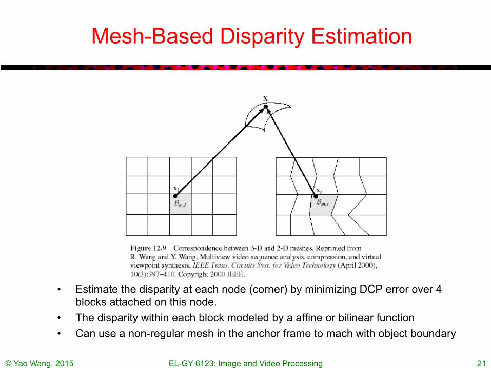
Mesh-Based Disparity Estimation
• Estimate the disparity at each node (corner) by minimizing DCP error over 4 blocks attached on this node.
• The disparity within each block modeled by a affine or bilinear function • Can use a non-regular mesh in the anchor frame to mach with object boundary

© Yao Wang, 2015 EL-GY 6123: Image and Video Processing 22

© Yao Wang, 2015 EL-GY 6123: Image and Video Processing 23
Intra-line edge matching using dynamic programing
Each point in the graph corresponds to one pair of left edge and right edge, with a corresponding matching cost. The problem is to find a path that has the minimal total cost. Because of the ordering constraint, the path cannot go backwards. The minimal cost path can be determined using dynamic programming.

Considering Occlusion in the Dynamic Programming Approach
© Yao Wang, 2015 EL-GY 6123: Image and Video Processing 24
M: matching L: appearing only in left R: appearing only in right
From [Scharstein02]
© Yao Wang, 2015 EL-GY 6123: Image and Video Processing 25
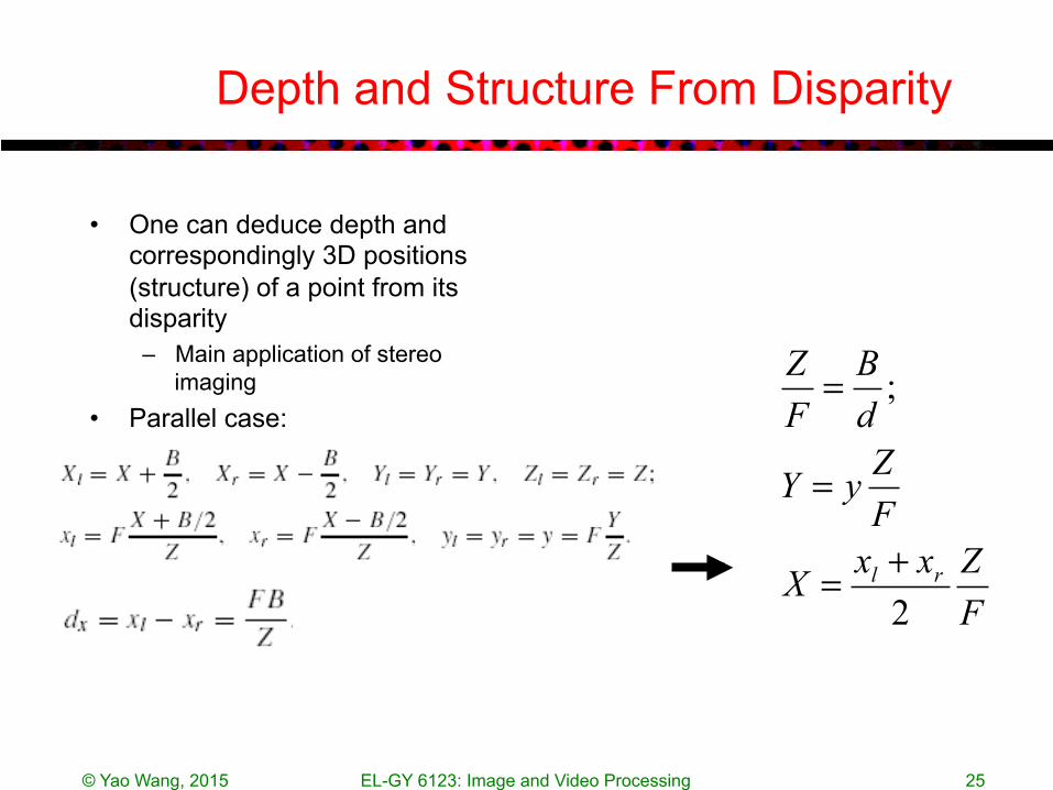
Depth and Structure From Disparity
• One can deduce depth and correspondingly 3D positions (structure) of a point from its disparity
– Main application of stereo imaging
• Parallel case:
FZxxX
FZyY
dB
FZ
rl
2
;
+=
=
=
© Yao Wang, 2015 EL-GY 6123: Image and Video Processing 26
Joint Motion and Structure Estimation
• Structure estimation: – Given nodes in one view, determine corresponding nodes in
another view – Based on the disparity at each node, determine the depth and
consequently 3D coordinate of the corresponding 3D point
• Motion estimation – Given nodes in a previous frame, find corresponding nodes in
the current frame, in both views
• Joint structure and motion estimation in video – Perform structure ad motion estimation jointly to minimize both
MCP and DCP errors – Still a challenging research problem

3D Camera / Depth Sensing
• Stereo camera – Depth from disparity, possibly with built-in algorithm for depth
estimation
• Depth camera – Time-of-flight (ToF): Shine a pulsed or modulated laser beam
(at ultraviolet, visible or infrared freq) to the imaged object and measure the total time the light travels for each pixel position. From round trip travel time, deduce the distance.
– LIDAR: a special ToF camera targeted for outdoor long distance observation (e.g. environment, urban mapping), typically by scanning the scene in raster order
• Microsoft Kinect: contain a depth sensor, a color camera, and a microphone array – Uses structured light illumination to deduce depth
© Yao Wang, 2015 EL-GY 6123: Image and Video Processing 27
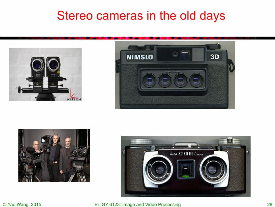
Stereo cameras in the old days
© Yao Wang, 2015 EL-GY 6123: Image and Video Processing 28

New 3D cameras: standalone, on laptop, smartphones
© Yao Wang, 2015 EL-GY 6123: Image and Video Processing 29

© Yao Wang, 2015 EL-GY 6123: Image and Video Processing 30
Intel, led by Brian Krzanich, says its RealSense technology is now small enough to fit in a smartphone, April 2015

Lidar in commercial applications
© Yao Wang, 2015 EL-GY 6123: Image and Video Processing 31
http://en.wikipedia.org/wiki/Lidar

How Kinect Deduce Depth?
– Project a speckle pattern of infrared light onto the scene
– Capture the reflected pattern – Compare the projected pattern and
reflected pattern to deduce depth
© Yao Wang, 2015 EL-GY 6123: Image and Video Processing 32
Information in following slides from [Hoiem-LectureNote] courses.engr.illinois.edu/cs498dh/fa2011/lectures/Lecture%2025%20-%20How%20the%20Kinect%20Works%20-%20CP%20Fall%202011.pdf

© Yao Wang, 2015 EL-GY 6123: Image and Video Processing 33
from [Hoiem-LectureNote]

Depth from Projector-Sensor
© Yao Wang, 2015 EL-GY 6123: Image and Video Processing 34
from [Hoiem-LectureNote]
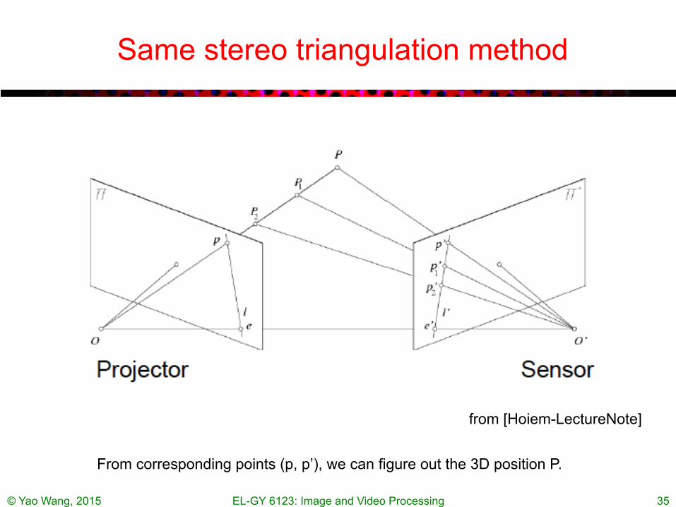
Same stereo triangulation method
© Yao Wang, 2015 EL-GY 6123: Image and Video Processing 35
From corresponding points (p, p’), we can figure out the 3D position P.
from [Hoiem-LectureNote]

Book vs. No Book: Depth by Matching Dots
© Yao Wang, 2015 EL-GY 6123: Image and Video Processing 36 from [Hoiem-LectureNote]

Book vs. No Book: Depth by Matching Dots
© Yao Wang, 2015 EL-GY 6123: Image and Video Processing 37

Natural light vs. projected IR stereo
© Yao Wang, 2015 EL-GY 6123: Image and Video Processing 38
From [Hoiem-Lecture]
© Yao Wang, 2015 EL-GY 6123: Image and Video Processing 39
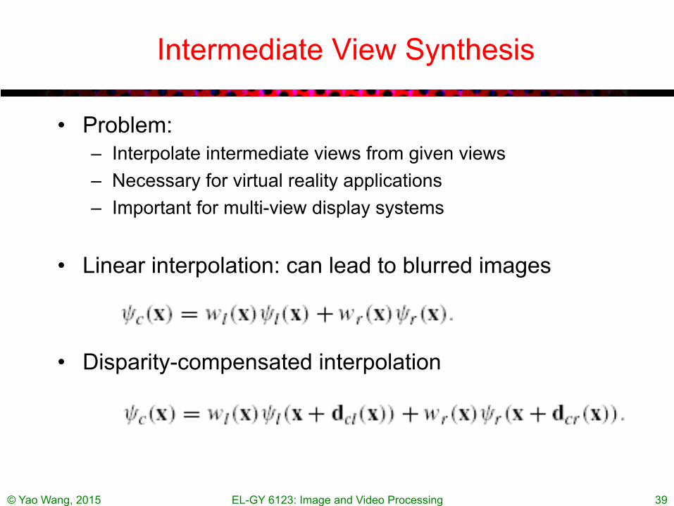
Intermediate View Synthesis
• Problem: – Interpolate intermediate views from given views – Necessary for virtual reality applications – Important for multi-view display systems
• Linear interpolation: can lead to blurred images
• Disparity-compensated interpolation
© Yao Wang, 2015 EL-GY 6123: Image and Video Processing 40
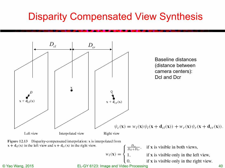
Disparity Compensated View Synthesis
clD crD
Baseline distances (distance between camera centers): Dcl and Dcr
© Yao Wang, 2015 EL-GY 6123: Image and Video Processing 41
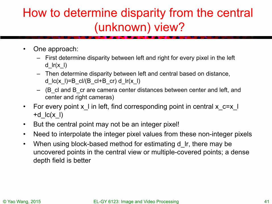
How to determine disparity from the central (unknown) view?
• One approach: – First determine disparity between left and right for every pixel in the left
d_lr(x_l) – Then determine disparity between left and central based on distance,
d_lc(x_l)=B_cl/(B_cl+B_cr) d_lr(x_l) – (B_cl and B_cr are camera center distances between center and left, and
center and right cameras) • For every point x_l in left, find corresponding point in central x_c=x_l
+d_lc(x_l) • But the central point may not be an integer pixel! • Need to interpolate the integer pixel values from these non-integer pixels • When using block-based method for estimating d_lr, there may be
uncovered points in the central view or multiple-covered points; a dense depth field is better

© Yao Wang, 2015 EL-GY 6123: Image and Video Processing 42
Mesh-Based Interpolation of Disparity Field
No uncovered or multiple covered pixels in central view!

© Yao Wang, 2015 EL-GY 6123: Image and Video Processing 43
Mesh-Based View Synthesis Result
© Yao Wang, 2015 EL-GY 6123: Image and Video Processing 44
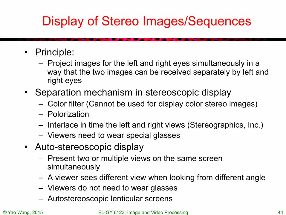
Display of Stereo Images/Sequences
• Principle: – Project images for the left and right eyes simultaneously in a
way that the two images can be received separately by left and right eyes
• Separation mechanism in stereoscopic display – Color filter (Cannot be used for display color stereo images) – Polorization – Interlace in time the left and right views (Stereographics, Inc.) – Viewers need to wear special glasses
• Auto-stereoscopic display – Present two or multiple views on the same screen
simultaneously – A viewer sees different view when looking from different angle – Viewers do not need to wear glasses – Autostereoscopic lenticular screens
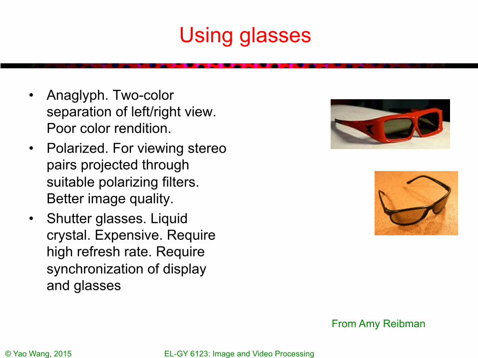
Using glasses
• Anaglyph. Two-color separation of left/right view. Poor color rendition.
• Polarized. For viewing stereo pairs projected through suitable polarizing filters. Better image quality.
• Shutter glasses. Liquid crystal. Expensive. Require high refresh rate. Require synchronization of display and glasses
© Yao Wang, 2015 EL-GY 6123: Image and Video Processing
From Amy Reibman

Autostereoscopic display principle
http://en.wikipedia.org/wiki/Parallax_barrier
• The viewer must be positioned in a well-defined spot to experience the 3D effect
• The effective horizontal pixel count viewable for each eye is reduced by one half
the effective horizontal pixel count viewable for each eye is reduced by one half
© Yao Wang, 2015 EL-GY 6123: Image and Video Processing
From Amy Reibman

3D-ready consumer TVs
• Display stereo pairs in time-sequential manner • Active shutter glasses
• Options – 3D DLP technology from TI (Samsung & Mitsubishi) – 3D plasma (Samsung)
EL-GY 6123: Image and Video Processing 47 © Yao Wang, 2015
From Amy Reibman
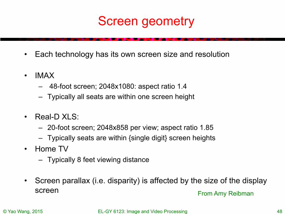
Screen geometry
• Each technology has its own screen size and resolution
• IMAX – 48-foot screen; 2048x1080: aspect ratio 1.4 – Typically all seats are within one screen height
• Real-D XLS: – 20-foot screen; 2048x858 per view; aspect ratio 1.85 – Typically seats are within {single digit} screen heights
• Home TV – Typically 8 feet viewing distance
• Screen parallax (i.e. disparity) is affected by the size of the display screen
© Yao Wang, 2015 EL-GY 6123: Image and Video Processing 48
From Amy Reibman

Mismatch in screen sizes and viewing distances (movie theater vs. home)
Objects appear to be in a puppet theater: small and close together
Same screen angle, smaller disparity. Result: different object size and distance
Real-life, and original intended screen size:
© Yao Wang, 2015 EL-GY 6123: Image and Video Processing 49
From Amy Reibman

Adaptation of disparity for different screen sizes
Same screen angle, shifted disparity. Result: same object size
Now, the object appears the correct size. However, objects are almost always behind the screen. Causing conflict of converging and accommodation
One way to “fix”: Shift one image relative to the other
Real-life, and original screen size:
© Yao Wang, 2015 EL-GY 6123: Image and Video Processing 50
From Amy Reibman
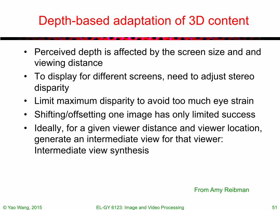
Depth-based adaptation of 3D content
• Perceived depth is affected by the screen size and and viewing distance
• To display for different screens, need to adjust stereo disparity
• Limit maximum disparity to avoid too much eye strain • Shifting/offsetting one image has only limited success • Ideally, for a given viewer distance and viewer location,
generate an intermediate view for that viewer: Intermediate view synthesis
© Yao Wang, 2015 EL-GY 6123: Image and Video Processing 51
From Amy Reibman

© Yao Wang, 2015 EL-GY 6123: Image and Video Processing 52
Coding of Stereo Sequences
• Simulcast: – Code each view independently
• Extension from block-based hybrid code: – Code one view using a standard video coder, using MCP
between successive frames in this view – Code the other view by using both DCP between views at the
same frame and MCP in the same view – MPEG-2 Multiview profile
• Mixed resolution – Code one view at the desired spatial/temporal resolution – Code another view with reduced spatial/temporal resolution
• More advanced, object-based approach
© Yao Wang, 2015 EL-GY 6123: Image and Video Processing 53
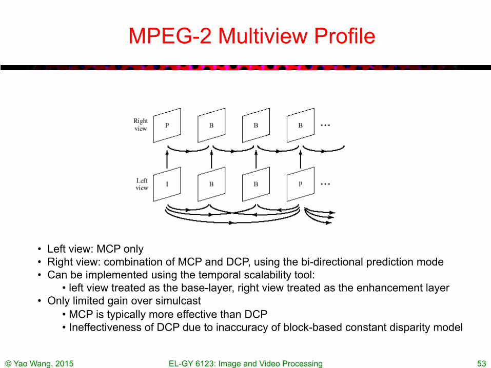
MPEG-2 Multiview Profile
• Left view: MCP only • Right view: combination of MCP and DCP, using the bi-directional prediction mode • Can be implemented using the temporal scalability tool:
• left view treated as the base-layer, right view treated as the enhancement layer • Only limited gain over simulcast
• MCP is typically more effective than DCP • Ineffectiveness of DCP due to inaccuracy of block-based constant disparity model
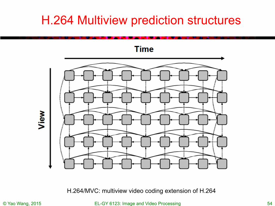
H.264 Multiview prediction structures
© Yao Wang, 2015 EL-GY 6123: Image and Video Processing 54
H.264/MVC: multiview video coding extension of H.264
HEVC Multiview Video + Depth (MVD)
• Two or more views • Assuming depth map at each view is available • Depth coding enable virtual view generation between
every two coded views • Allow encoding/decoding of color frames only • Coding of dependent views using DCP, inter-view
motion prediction, and inter-view residual prediction • Depth map coded using new intra-coding modes,
modified motion compensation and motion vector coding, and motion parameter inheritance from the associated video component
© Yao Wang, 2015 EL-GY 6123: Image and Video Processing 55
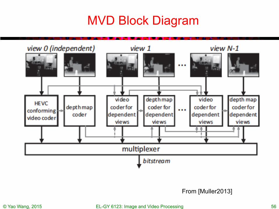
MVD Block Diagram
© Yao Wang, 2015 EL-GY 6123: Image and Video Processing 56
From [Muller2013]

l Brighter objects closer, dark objects further away
Examples of depth maps
JBoyce, 2011
© Yao Wang, 2015 EL-GY 6123: Image and Video Processing 57
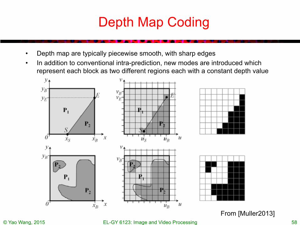
Depth Map Coding
• Depth map are typically piecewise smooth, with sharp edges • In addition to conventional intra-prediction, new modes are introduced which
represent each block as two different regions each with a constant depth value
© Yao Wang, 2015 EL-GY 6123: Image and Video Processing 58
From [Muller2013]

Barriers to mass market
• Data and delivery format • Quality of 3D video production
– Content creators must be aware of 3D videography – Re-purposing of 3D content from cinema into the homes – 2D->3D conversion: converting old 2D movie to 3D
• Human factors – Stereoscopic glasses are no fun – Auto-stereoscopic has its own issues – Avoid objectionable 3D effects
© Yao Wang, 2015 EL-GY 6123: Image and Video Processing 59
From Amy Reibman
Additional perceptual issues
• Both too much depth and too many fast changes of depth cause visual fatigue
• Conflicting depth information causes visual fatigue – Accommodation and vergence are linked when scanning the
scene (but can be decoupled over time) – Compression, aliasing, other impairments (like keystoning) can
make fusing more difficult – Screen or glasses scratch or dust
• Cross-talk – Left eye sees some of what Right eye should see – Stronger in high-contrast and large-disparity areas – (But fusing is easier in high-contrast areas)
© Yao Wang, 2015 EL-GY 6123: Image and Video Processing 60
From Amy Reibman
© Yao Wang, 2015 EL-GY 6123: Image and Video Processing 61
Summary
• Human perception of depth • Principle in stereo imaging:
– Relation between depth and disparity for parallel set-up and other more general camera set-ups.
– Epipolar constraint for an arbitrary set-up • Disparity estimation:
– Formulation as an optimization problem similar to motion estimation – Block-based approach – Mesh-based approach: regular mesh vs. adaptive mesh – Dynamic programming: not required – Joint motion and structure estimation: not required
• 3D cameras: difference ways of depth sensing • Intermediate view synthesis • Stereo/multiview sequence coding
– Extension from standard video coder: Joint MCP and DCP – Multiview + Depth coding
• Stereo image/video display
© Yao Wang, 2015 EL-GY 6123: Image and Video Processing 62
Homework
• Review questions – Describe briefly how the human being deduce depth from disparity. A
far away object has small or large disparity? – Describe how a stereo camera deduce depth – Describe how Kinect camera deduce depth – Describe 3 different ways of depth sensing for 3D imaging – Describe the general principle of intermediate view synthesis – Describe briefly how to code a stereo video using both motion
compensated prediction and disparity compensated prediction • Written Homework
– Prob. 12.1 – Prob. 12.2

Computer Assignment (Optional)
• Write a program that can estimate the horizontal disparity map between two stereo images captured using parallel set up. To estimate the disparity at each pixel, apply EBMA over a block centered at this pixel. Apply your program to any stereo image pair you can download (e.g. from Middlebury stereo database).
• Prob. 12.9 • Prob. 12.11
© Yao Wang, 2015 EL-GY 6123: Image and Video Processing 63

Recommended Readings
• [Wang2002]: Chap 12 • Depth estimation from stereo images:
– D. Scharstein and R. Szeliski. A taxonomy and evaluation of dense two-frame stereo correspondence algorithms. IJCV 2002.
http://vision.middlebury.edu/stereo/taxonomy-IJCV.pdf http://vision.middlebury.edu/stereo/ (an excellent website)
– Y. Ohta and T. Kanade. Stereo by intra- and interscanline search using dynamic programming. IEEE TPAMI, 7(2):139–154, 1985.
• Kinect – Derek Hoiem, Lecture note on Kinect,
courses.engr.illinois.edu/cs498dh/fa2011/lectures/Lecture%2025%20-%20How%20the%20Kinect%20Works%20-%20CP%20Fall%202011.pdf
© Yao Wang, 2015 EL-GY 6123: Image and Video Processing 64

Recommended Readings
• Stereo and multiview coding – A Vetro, T Wiegand, GJ Sullivan, Overview of the stereo and multiview video
coding extensions of the H. 264/MPEG-4 AVC standard, Proceedings of the IEEE, 2011, 99 (4):626-642.
– Muller, K.; Schwarz, H.; Marpe, D.; Bartnik, C.; Bosse, S.; Brust, H.; Hinz, T.; Lakshman, H.; Merkle, P.; Rhee, F.H.; Tech, G.; Winken, M.; Wiegand, T., "3D High-Efficiency Video Coding for Multi-View Video and Depth Data," Image Processing, IEEE Transactions on , vol.22, no.9, pp.3366,3378, Sept. 2013
• Stereo and autostereoscopic display – A. Woods, T. Docherty, and R. Koch, “Image distortions in
stereoscopic video systems”, Proceedings SPIE Stereoscopic Displays and Applications IV, vol. 1915, San Jose, CA, Feb. 1993.
– Dodgson, N.A., "Autostereoscopic 3D Displays," IEEE Computer Magazine, vol.38, no.8, pp.31,36, Aug. 2005
– Lecture note by Neil Dodgson, multi-view autostereoscopic display http://www.cl.cam.ac.uk/~nad10/pubs/Stanford3D-2011.pdf
© Yao Wang, 2015 EL-GY 6123: Image and Video Processing 65


![arXiv:1609.05561v1 [cs.CV] 18 Sep 2016 · Keywords: Multiview Stereo, 3D reconstruction, 3D curve networks, Junctions 1 Introduction The automated 3D reconstruction of general scenes](https://static.documents.pub/doc/80x56/5e4c62ff0a5bf5223055b795/arxiv160905561v1-cscv-18-sep-2016-keywords-multiview-stereo-3d-reconstruction.jpg)


