Ken Kamrin and Martin Z. BazantDepartment of Mathematics, Massachusetts Institute of Technology, Cambridge, Massachusetts 01239, USA
�Received 15 September 2006; published 11 April 2007�
There have been many attempts to derive continuum models for dense granular flow, but a general theory isstill lacking. Here, we start with Mohr-Coulomb plasticity for quasi-two-dimensional granular materials tocalculate �average� stresses and slip planes, but we propose a “stochastic flow rule” �SFR� to replace theprinciple of coaxiality in classical plasticity. The SFR takes into account two crucial features of granularmaterials—discreteness and randomness—via diffusing “spots” of local fluidization, which act as carriers ofplasticity. We postulate that spots perform random walks biased along slip lines with a drift direction deter-mined by the stress imbalance upon a local switch from static to dynamic friction. In the continuum limit�based on a Fokker-Planck equation for the spot concentration�, this simple model is able to predict a varietyof granular flow profiles in flat-bottom silos, annular Couette cells, flowing heaps, and plate-draggingexperiments—with essentially no fitting parameters—although it is only expected to function where material isat incipient failure and slip lines are inadmissible. For special cases of admissible slip lines, such as platedragging under a heavy load or flow down an inclined plane, we postulate a transition to rate-dependentBagnold rheology, where flow occurs by sliding shear planes. With different yield criteria, the SFR provides ageneral framework for multiscale modeling of plasticity in amorphous materials, cycling between continuumlimit-state stress calculations, mesoscale spot random walks, and microscopic particle relaxation.
For centuries, engineers have described granular materialsusing continuum solid mechanics �1–3�. Dense granular ma-terials behave like rigid solids at rest, and yet are easily setinto liquidlike, quasisteady motion by gravity or movingboundaries, so the classical theory is Mohr-Coulomb plastic-ity �MCP�, which assumes a frictional yield criterion. Thesimplest model is the two-dimensional “Ideal Coulomb Ma-terial” at limit state, where the maximum ratio of shear tonormal stress is everywhere equal to a constant �the internalfriction coefficient�, whether or not flow is occurring. Thismodel is believed to describe stresses well in static or flow-ing granular materials, but, as we explain below, it fails topredict flow profiles, when combined with the usual coaxialflow rule of continuum plasticity. Indeed, it seems continuummechanics has not yet produced a simple and robust modelfor granular flow.
In recent years, the sense that there is new physics to bediscovered has attracted a growing community of physiciststo the study of granular materials �4–9�. Unlike the engi-neers, their interest is mostly at the discrete particle level,motivated by the breakdown of classical statistical mechan-ics and hydrodynamics due to strong dissipation and long-lasting, frictional contact networks. Dense granular materialsexhibit many interesting collective phenomena, such as forcechains, slow structural relaxation, and jamming. Similar non-equilibrium phenomena occur in glasses, foams, and emul-sions, as in granular materials, so it is hoped that a generalnew statistical theory may emerge. Presumably from such amicroscopic basis, continuum models of glassy relaxationand dense granular flow could be systematically derived, justas dissipative hydrodynamics for granular gases can be de-rived from kinetic theory with inelastic collisions �10�.
This dream has not yet been achieved, but many empiricalcontinuum models have been proposed �4,9,11�. The diffi-
culty in describing dense granular flow is evidenced by theremarkable diversity of physical postulates, which include:coupled static and rolling phases �12–15�, Bagnold rheology�16� based on “granular eddies” �17�, granular temperature-dependent viscosity �18�, density-dependent viscosity�19,20�, nonlocal stress propagation along arches �21�, self-activated shear events due to nonlocal stress fluctuations�22,23�, free-volume diffusion opposing gravity �24–28�,“shear transformation zones” coupled to free-volume kinet-ics �29,30�, and partial fluidization governed by a Landau-like order parameter �31,32�. Each of these theories can fit asubset of the experimental data �33�, usually only for a spe-cific geometry for which it was designed, such as a flowingsurface layer �12–15,31�, inclined plane �16,17�, Couette cell�19,20�, inclined chute �22,23�, or wide silo �24–28�, andnone seems to have very broad applicability. For example,we are not aware of a single model, from physics or engi-neering, which can predict velocity profiles in both drainingsilos and annular Couette cells, even qualitatively.
The theory of partial fluidization of Aranson and Tsimringhas arguably had the most success in describing multipleflows within a single theoretical framework �31,32�. Al-though setting boundary conditions for the order parameterusually requires additional ad hoc assertions, the model isnonetheless able to reproduce known flow behavior in in-clined chutes, avalanches, rotating drums, and simple shearcells without many fitting parameters. It also describes someunsteady flows. However, the theory lacks any clear micro-scopic foundation and is not directly coupled to a constitu-tive stress model for static materials. As such, it has onlybeen applied to problems with very simple solid stress fields,limiting its current applicability to flows that depend on onlyone spatial variable.
In an attempt to describe arbitrary geometries, such assilos and Couette cells, we take the view that the engineersmay already have a reasonable continuum description of the
mean stresses, so we start with Mohr-Coulomb plasticity.However, discreteness and randomness clearly need to betaken into account in a granular material. For static stresses,quenched randomness in material properties is known to leadto statistical slip-line blurring in “stochastic plasticity” �34�,but this says nothing about how plastic yielding actually oc-curs.
To describe yielding dynamics, we propose a “stochasticflow rule” �SFR� where local fluidization �stick-slip transi-tion� propagates randomly along blurred slip lines. We buildon the recently proposed spot model for random-packing dy-namics �27� by viewing “spots” of free volume as carriers ofplasticity in granular materials, analogous to dislocations incrystals. Multiscale spot simulations can reproduce quite re-alistic flowing packings in silo drainage �28�; here, we intro-duce a mechanical basis for spot motion from MCP, whichleads to a theory of considerable generality for bulk granularflows.
The paper is organized as follows. Since plasticity is un-familiar to most physicists, we begin by reviewing key con-cepts from MCP in Sec. II, both for stresses and for denseflows. In Sec. III, we highlight various shortcomings of theclassical theory, many of which we attribute to the coaxialflow rule. We then introduce the general spot-based SFR anda specific simplification to be used for granular flow in Sec.IV. Next we apply the theory to four prototypical examples:Silo, Couette, heap, and plate-dragging flows in Sec. V. Thenin Sec. VI, we explain how the last two examples indicate asmooth transition from the SFR to Bagnold rheology, whenslip lines become admissible, and we present a simple com-posite theory, which extends the applicability of the model tovarious shear flows. In Sec. VII, we conclude by furtherclarifying the range of applicability of the SFR and possibleextensions to other granular flows and different materials.
II. CONCEPTS FROM CONTINUUM MECHANICS
A. Mohr-Coulomb plasticity: Stresses
In the eighteenth century, it was Coulomb, as a militaryengineer designing earthen fortresses, who introduced theclassical model of a granular material, which persists to thepresent day: A continuous medium with a frictional yieldcriterion. His ideas were expressed in general continuum-mechanical terms by Mohr a century later, and a modernmathematical formulation of “Mohr-Coulomb plasticity”�MCP�, which we also use below, is due to Sokolovskii �2�.Although other mechanical models exist, such as Drucker-Prager plasticity �35�, MCP is perhaps the simplest and mostwidely used for granular materials in engineering �1�. Assuch, we choose to build our model of dense granular flowon the MCP description of stresses, as a reasonable and time-tested first approximation.
We begin in this section by reviewing relevant conceptsfrom MCP, e.g. following Nedderman �1�. The fundamentalassumption is that a granular material can be treated as an“ideal Coulomb material” �ICM�, i.e., a rigid-plastic continu-ous media which yields according to a Coulomb yield crite-rion
��/�� = � � tan � , �1�
where � is the shear stress, � is normal stress, and � theinternal friction angle, akin to a standard friction law with nocohesion. Throughout, we accept the common tensorial con-ventions for stresses with the key exception that normalstresses are deemed positive in compression. This is a stan-dard modification in the study of noncohesive granular ma-terials since granular assemblies cannot support tension. Wewill also focus entirely on quasi-two-dimensional �2D� ge-ometries.
Consider a small material element in static equilibriumand with no body forces present �see Fig. 1�. The normalstresses �xx and �yy can differ and the shear stresses �xy and�yx must be equal in order to balance moments. Likewise thevariable �yx is redundant and will not be used again in thispaper. To determine the stresses along any angle within thiselement, we place a new boundary within the material atsome desired angle � and observe force balance on thewedge that remains �see Fig. 2�. After algebraic simplifica-tion, this gives
�� =1
2��xx + �yy� +
1
2��xx − �yy�cos 2� − �xy sin 2� ,
FIG. 1. Stresses on a material element. All vectors are pointingin the positive direction as per our sign convention.
FIG. 2. Force diagram for a wedge. Hypotenuse length assignedto unity.
KEN KAMRIN AND MARTIN Z. BAZANT PHYSICAL REVIEW E 75, 041301 �2007�
041301-2
�� =1
2��xx − �yy�sin 2� + �xy cos 2� .
Now define
p =1
2��xx + �yy� ,
tan 2� =− 2�xy
�xx − �yy,
R =���xx − �yy
22
+ �xy2 ,
which allows us to write
�� = p + R cos�2� − 2�� , �2�
�� = R sin�2� − 2�� . �3�
This implies that for all angles �, the locus of tractionstresses ��� ,��� is a circle centered at �p ,0� with radius R.This circle is referred to as “Mohr’s circle.”
We have just derived Mohr’s circle without accounting forthe possible effects of body forces acting on the materialelement and gradients in the stress field. Adjusting for theseeffects, however, would change the results only negligibly asthe element gets small in size. If we were to apply the sameforce-balancing analysis to a differentially small material el-ement with a body force and stress gradients, we would findthat the stress differences on the walls and the inclusion ofthe differentially small body force within only add differen-tially small terms to the equations for �� and ��. Thus we canalways use Mohr’s Circle to obtain traction stresses along adesired angle.
To ultimately define a full stress state for the materialelement, we need one more equation—we have three stressvariables and only two force balance equations:
��xx
�x−
��xy
�y= Fbody
x , �4�
��yy
�y−
��xy
�x= Fbody
y . �5�
We say a material element is at incipient failure if the yieldcriterion is fulfilled along some direction and �� /���� alongall others. A material in which incipient failure occurs ever-where is said to be at a limit state. In a limit state, the Mohr’scircle at every point in the material must be tangent to thelocus �� /��=�. As can be seen by applying trigonometry inFig. 3, this requirement means that R= p sin �, enabling us toparametrize the stresses in terms of p and � only, therebyclosing the equations. For this reason, we restrain our anlysisto limit-state materials and refer to p and � as the stressparameters or Sokolovskii variables. �The limit-state stresstreatment described here is also known as “slip-line theory;”to avoid possible confusion, we specify this is not equivalentto limit analysis plasticity concerned with upper and lowercollapse limits.�
Solving for the original stress variables in terms of thestress parameters gives
�xx = p�1 + sin � cos 2�� , �6�
�yy = p�1 − sin � cos 2�� , �7�
�xy = − p sin � sin 2� . �8�
Using these expressions, we rewrite Eqs. �4� and �5�:
�1 + sin � cos 2��px − 2p sin � sin 2��x + sin � sin 2�py
+ 2p sin � cos 2��y = Fbodyx ,
sin � sin 2�px + 2p sin � cos 2��x + �1 − sin � cos 2��py
+ 2p sin � sin 2��y = Fbodyy .
These will be referred to as the “stress balance equations.”They form a hyperbolic system and thus can be solved usingthe method of characteristics. The system reduces to the fol-lowing two characteristic equations:
dp � 2p�d� = Fbodyy �dy � �dx� + Fbody
x �dx ± �dy�
along curves fulfilling
dy
dx= tan�� � � . �9�
To solve the stress balance equations, mesh the two familiesof characteristic curves in the bulk, then march from theboundaries in, progressively applying the two differential re-lationships above to approximate the stress parameters ateach intersection point in the mesh. More on this can befound in �36�. Other ways to solve the stress balance equa-tions include the two-step Lax-Wendroff method �37� and theGalerkin method �38�.
We return now to Mohr’s circle for a discussion of thestress properties within a differential material element. Equa-tions �2� and �3� show that Mohr’s circle can be used as aslide rule to determine the stresses along any angle �: Onearrives at the point ��� ,��� by starting at ��xx ,�xy� and trav-eling counterclockwise around Mohr’s circle for 2� radians�see Fig. 3�. Also note on the diagram that the stresses alongthe x and y directions lie along a diameter of Mohr’s circle;any two material directions differing by an angle of /2 lie
FIG. 3. Using Mohr’s circle jointly with the Coulomb internalyield locus ��= ±��� to determine the traction stresses along anyplane within a material element.
STOCHASTIC FLOW RULE FOR GRANULAR MATERIALS PHYSICAL REVIEW E 75, 041301 �2007�
041301-3
along a diameter of the corresponding Mohr’s circle dia-gram. Utilizing this property in reverse is perhaps the easiestway to draw Mohr’s circle in the first place; draw the uniquecircle for which ��xx ,�xy� and ��yy ,−�xy� are end points of adiameter.
Let ��1 ,0� and ��3 ,0� be the points of intersection be-tween Mohr’s circle and the � axis, where �1��3. Thesepoints correspond to the two lines within a material elementalong which the shear stress vanishes and the normal stress ismaximal or minimal. �1 ��3� is called the major �minor�principal stress and the line on which it acts is called themajor �minor� principal plane.
Mohr’s circle shows that the major principal plane occursat an angle � counterclockwise from the vertical �see Fig. 3�.Thus the major principal stress points along an angle � coun-terclockwise from the horizontal. This is the standard physi-cal interpretation of �. One might think of � as the anglefrom the horizontal along which a force chain would be pre-dicted to lie.
By right-triangle geometry, a line segment connecting thecenter of Mohr’s circle to a point of tangency with the inter-nal yield locus would make an angle of /2−� with the �axis. Each point of tangency represents a direction alongwhich the yield criterion is met, i.e., a slip line. Mohr’s circleindicates that the slip lines are angled � /2−�� /2 up anddown from the minor principal plane. But since the majorand minor principal planes are orthogonal, the major princi-pal stress points along the minor principal plane. Defining= /4−� /2, we deduce that slip lines occur along theangles �± measured counterclockwise from the horizontal.Looking back at the characteristic equations, we see that theslip lines and the characteristic curves coincide. This meansthat information from the boundary conditions propagatesalong the slip lines to form a full solution to the stress bal-ance equations. �See Fig. 4�.
It is worth noting that the stress balance equations arewritten for static materials and do not appear to account for
dynamic behavior like dilatancy and convection stresses. Thetheory of critical state soil mechanics �39� was the first torigorously approach the issue of dilatancy �see the Appen-dix�. It concludes that when material attains a flow state inwhich the density field stops changing in time, all points inthe flow lie along a critical state line of the form �� /��=� for� constant. Since this exactly mirrors the Coulomb yield cri-terion, we can keep the stress balance equations and utilize�=� �as in �40��. As for convection, adding the u ·�u terminto the stress equations couples the stresses to the velocityand makes the problem very difficult to solve. The practiceof ignoring convection is justified by our slow-flow require-ment and is commonly used and validated in basic solidmechanics literature �1–3�. So we conclude that dynamic ef-fects in flowing materials do not preclude the use of thestress balance equations in slow, steady flows.
B. Mohr-Coulomb plasticity: Flow rules
To calculate flow, we assert incompressibility and a flowrule—the flow rule is a constitutive law chosen to reflect thegeneral behavior of the material at hand. The continuousnature of the ICM assumption suggests that symmetry shouldbe kept with respect to the principal stress planes. Based onthis, Jenike proposed adopting the coaxial flow rule. Theprinciple of coaxiality claims that material should flow byextending along the minor principal stress direction and con-tracting along the major principal stress direction; the prin-cipal planes of stress are aligned with the principal planes ofstrain rate. The intuition for this constitutive rule is shown inFig. 5. Mathematically, this means that in a reference framewhere the minor and major principal stress directions are thebasis, the strain-rate tensor should have no off-diagonal com-ponents, i.e.,
R�ER�T �10�
is diagonal, where R� rotates counterclockwise by � and E isthe strain-rate tensor
E =1
2��u + ��u�T� , �11�
where u= �u ,v� is the velocity. Calculating the �1,2� compo-nent of the matrix in Eq. �10� and setting it to zero gives theequation of coaxiality,
FIG. 4. Important lines intersecting each material point: �a� Ma-jor principal plane/minor principal stress direction; �b� minor prin-cipal plane/major principal stress direction; �c�, �d� slip lines.
FIG. 5. �Color online� Sketch of the coaxial flow rule.
KEN KAMRIN AND MARTIN Z. BAZANT PHYSICAL REVIEW E 75, 041301 �2007�
041301-4
�u
�y+
�v�x
= � �u
�x−
�v�ytan 2� . �12�
This flow rule has played a dominant role in the developmentof continuum plasticity theory and will be closely analyzedin this work.
Coaxiality with incompressibility comprises another hy-perbolic system of equations enabling the velocity field to besolved via characteristics:
du + tan�� � /4�dv = 0
along curves fulfilling
dy
dx= tan�� � /4� . �13�
So, given ��x ,y� from the stress balance equations, informa-tion about the flow travels from the boundaries into the bulkalong curves rotated /4 off from the principal stressplanes—using Mohr’s circle, we observe that these are thelines for which the shear stress is maximal �and the normalstresses are equal�.
Other flow rules have been suggested instead of coaxial-ity. Of specific note, Spencer �41� has proposed the double-shearing flow rule. Unlike coaxiality which can be under-stood as a simultaneous equal shearing along both slip-linefamilies, double-shearing allows the shearing motion to beunequally distributed between the two families in such a waythat the flow remains isochoric. For steady flows, the double-shearing flow rule is
sin 2�� �u
�x−
�v�y − cos 2�� �v
�x+
�u
�y
= sin �� �v�x
−�u
�y− 2u · �� . �14�
It can be seen that when the material neighboring a particlerotates in sync with the rotation of the principal planes �i.e.,as tracked by the rate of change of ��, the right side goes tozero and the rule matches coaxiality. Under double shearing,the characteristics of stress and velocity align, easing manyaspects of the numerics. Some recent implementations ofgranular plasticity have utilized principles of double shearing�42�. Though in this paper we deal primarily with the com-parison of coaxiality to our new theory, this equation will bementioned again in a later section.
C. Rate-independence concept
We now more fully address the conceptual basis for theflow theory just introduced. The theory is fundamentally dif-ferent from traditional fluids where force balance �includingconvection and viscous stresses in the case of Newtonianfluids� can be used alongside incompressibility to fully de-termine the fluid velocity and pressure fields. Unlike a fluid,granular materials can support a static shear stress and thusforce balance plus incompressibility alone is an undercon-strained system. Rather, the stress constitutive law for granu-lar material is presumed to be rate independent in the slow,quasistatic regime we study.
This concept is best understood tensorially. We can re-write the equations of coaxiality and incompressibilityequivalently as
E = �T0, �15�
where
T = stress tensor = �− �xx �xy
�xy − �yy , �16�
T0 = T −1
2�trT�I = deviatoric stress tensor, �17�
and � is a multiplier which can vary in space. Equation �12�is merely the ratio of the �1,2� component and the differenceof the �2,2� and �1,1� components of Eq. �15�, thus cancelling�, and incompressibility is automatic since we relate to thedeviatoric stress tensor. Equation �15� gives a simple andhighly general form for plastic material deformation appli-cable to a broad range of deformable materials and so it isideal for illustrating the role of rate dependency. In MCP, wesolve for T0 a priori from the stress balance equations. �adds the extra degree of freedom necessary to make sure thestrain-rate field is actually compatible with a real velocityfield—� is not any specific function of the stress or strain-rate variables and it adjusts to fit different velocity boundaryconditions. Thus the stress alone does not imply the strainrate and vice versa.
Supposing, on the other hand, that we were dealing with arate-dependent �i.e., viscoplastic� material like Newtonianfluid, the above tensorial equation would still apply but wecannot claim to know T0 in advance since material motionchanges the stresses. Instead we prescribe a functional formfor �, like �=viscosity−1=const, and write the force balance
equations in terms of E. Thus E is computed very differentlyfor the two cases: in the rate-independent case, Eq. �15� issolved using a known form for T0 and in the rate-dependentcase, Eq. �15� is solved using a known form for �.
The physical intuition for rate-independent flow can beeasily understood with an example. Suppose we slide twofrictional blocks against each other at two different nonzerosliding rates. In most rudimentry dry friction laws, the shearstress required to slide one block against another is propor-tional to the normal stress—there is no mention whatsoeverof the rate of sliding. Thus the two sliding rates are modeledto be attainable with the same shear stress and likewise thestress-strain relationship is deemed rate independent. Forslow granular flows with long-lasting interparticle contacts,comparisons with this example are especially instructive.
III. SHORTCOMINGS OF MOHR-COULOMBPLASTICITY
The use of the stress balance equations with incompress-ibility and the coaxial flow rule will be referred hitherto asMohr-Coulomb plasticity �MCP�. The theory has the benefitof being founded on mechanical principles, but does havesome marked drawbacks. We point out a few as follows.
STOCHASTIC FLOW RULE FOR GRANULAR MATERIALS PHYSICAL REVIEW E 75, 041301 �2007�
041301-5
�a� The theory frequently predicts highly discontinuousvelocity fields.
�b� The coaxial flow rule is conceptually troubling insome simple geometries.
�c� The assumption of limit-state stresses is overreaching.�d� MCP is a continuum theory and thus cannot model
discreteness and randomness.
We will now discuss these four points in detail.
A. Discontinuous “shocks” in stress and velocity
MCP’s two stress PDE’s and two flow PDEs are eachfully hyperbolic systems meaning that continuous solutionsdo not necessarily exist for arbitrary choices of the boundaryconditions. Instead, discontinuous solutions are constructedutilizing intuitive jump conditions. For stresses, a jump in thestress parameters across a discontinuity line is only allow-able if such a jump places no net forces on a small controlvolume surrounding the line thereby ensuring particle stabil-ity. This means the normal and shear stresses along the di-rection of the discontinuity must be the same on both sides ofthe discontinuity. However, the normal stress along the per-pendicular direction can have a jump upon crossing the dis-continuity as this places no net force on the control volume�see Fig. 6�.
In terms of the stress parameters, this means that p and �can jump as long as
�1 + sin � cos�2� − 2�B���1 + sin � cos�2� − 2�A��
=sin�2� − 2�B�sin�2� − 2�A�
=pA
pB , �18�
where � is the angle from the vertical along which the stressdiscontinuity lies.
As for velocity, incompressibility forces us to impose asimpler jump rule in that the component tangent to the ve-locity discontinuity is the only one allowed to jump. We notethat whenever a stress shock exists, the jump in the stressparameters will usually place a jump in the flow rule andmay cause a velocity discontinuity to form coincident withthe stress shock. A velocity discontinuity can form evenwhen the stress field is smooth since the velocity PDEs arethemselves hyperbolic. �It is worth noting that when shocksare allowed in the solution, multiple solutions sometimes
arise to the same problem; introduction of the so-called “en-tropy condition” can be used to choose the best of the pos-sible solutions �1,43�.� Overall, the MCP equations are math-ematically very poorly behaved, and have also been shownto give violent instabilities and finite-time singularities�44,45�.
Aside from its mathematical difficulties, MCP theory alsodoes not match experiments or our everyday experience ofgranular flows. In particular, MCP commonly predicts com-plicated patterns of velocity discontinuities in situationswhere experiments indicate smooth flow in steady state. InFig. 7, the numerically determined stress field for a wedgehopper with only slightly nonradial boundary conditions onthe top surface exhibits a fanlike array of shocks �92�. Theassociated velocity field �not shown� will at best exhibit asimilar pattern of discontinuities and at worse add even morediscontinuities. Such a broken velocity field is clearly un-physical. As the grain size becomes very small �sands�, dis-continuous velocity fields with no relationship to the stressfield have been observed, but these are only temporary; theshocks commonly blur away immediately after the onset offlow, which has been attributed to some instability mecha-nism �46�. Literature on the topic �1� is quick to concede thatinfinitessimally sharp velocity jumps are physically nonsen-sical and should be understood as being spread over at leasta few particle widths. Below, we will see that our modelnaturally provides a mechanism for the blurring of velocityshocks even in the presence of a stress shock, with largevelocity variations occurring only at the scale of several par-ticle diameters.
Typically, to avoid the task of having to track or captureshocks in the various fields, approximations to MCP are in-voked which give continuous solutions either by altering theboundary conditions or simplifying the PDE’s. Smooth stressapproximations are especially useful when attempting tosolve for the velocity field—tracking flow shocks comingfrom both a discontinuous stress field and hyperbolicity inthe velocity equations is an enormous job. To our knowledge,
FIG. 6. Stresses on a control volume intersected by a disconti-nuity. Note how a jump in �� places no net force on the controlvolume.
FIG. 7. Numerical solution to MCP in a wedge hopper withnonradial stresses on the top boundary. Normal stress in the radialdirection displayed �92�.
KEN KAMRIN AND MARTIN Z. BAZANT PHYSICAL REVIEW E 75, 041301 �2007�
041301-6
a full solution to MCP has never been obtained either nu-merically or analytically in cases where the underlying stressfield has shocks. Instead, shock-free approximate solutionshave mostly been pursued.
Arguably, the two most successful and commonly usedresults of MCP are actually approximations, not full solu-tions. The Jenike Radial Solution �40,47� for wedge hopperflow solves the MCP equations exactly, and with no discon-tinuities, but does not allow for a traction free top surface. Itis a similarity solution of the form
p = rf��� , �19�
� = g��� , �20�
v� = −h���
rr , �21�
which reduces the four MCP PDE’s to a system of threeODE’s with �r ,�� the position �r=distance from the hopperapex and � is measured anticlockwise from the vertical�.Though this solution enables the material to obey a wallyield criterion along the hopper walls, the stress parametersat the top surface have very little freedom. This is why mostclaim the radial solution to only hold near the orifice, con-siderably away from the actual top surface.
Another commonly used simplification is called themethod of differential slices, although it only applies tostresses and not flow �our focus here�. Originally proposedby Janssen in 1895 and significantly enhanced since then, itis used to determine wall stresses in bins and containers. Themethod makes some very far-reaching assumptions about theinternal stresses: p is presumed to only depend on height andthe � field is assumed to be identically /2 or 0. Theseassumptions reduce the stress balance equations to one ODEand ultimately give the famous result that wall stresses in-crease up to a certain depth and then saturate to a constantvalue. �This saturation behavior is not a byproduct of theapproximation; the discontinuous, full solution to the stressbalance equations in a bin also gives similar stress saturationbehavior.� While this effect has been verified extensively inexperiment, the underlying assumptions clearly cannot holdsince, for example, the walls exert an upward shear stress onthe material which contradicts the assumption about � �1�.
In summary, the equations of MCP theory have very lim-ited applicability to granular flows. There are very few, ifany, solutions available �either numerical or analytical� formany important geometries such as planar or annular Cou-ette cells, vertical chutes, inclined places, etc. In the case ofsilos, MCP has been used extensively to describe stresses,although the equations are difficult to solve and poorly be-haved from a mathematical point of view, as noted above.There have also been some attempts to use MCP to describegranular drainage from silos, in conjunction with the coaxialflow rule, but this approach has met with little success, as wenow elaborate.
B. Physical difficulties with coaxiality
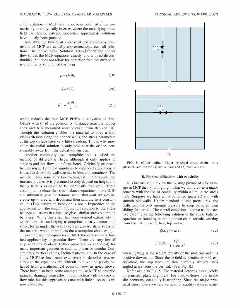
It is instructive to review the existing picture of silo drain-age in MCP theory, to highlight what we will view as a majorconcern with the use of coaxiality within a limit-state stressfield. Suppose we have a flat-bottomed quasi-2D silo withsmooth sidewalls. Under standard filling procedures, thewalls provide only enough pressure to keep particles fromsliding farther out. These wall conditions, known as the “ac-tive case,” give the following solution to the stress balanceequations as found by marching down characteristics startingfrom the flat, pressure free, top surface:
��x,y� = /2, �22�
p�x,y� =fgy
1 + sin �, �23�
where fg� g is the weight density of the material and y ispositive downward. Since the � field is identically /2 ev-erywhere, the slip lines are thus perfectly straight linesangled at ± from the vertical. �See. Fig. 8.�
Refer again to Fig. 5. The material deforms based solelyon principal plane alignment. For a slow, dense flow in thesilo geometry, coaxiality is troubling. Since the major prin-cipal stress is everywhere vertical, coaxiality requires mate-
FIG. 8. �Color online� Major principal stress chains in aquasi-2D silo for the �a� active case and �b� passive case.
STOCHASTIC FLOW RULE FOR GRANULAR MATERIALS PHYSICAL REVIEW E 75, 041301 �2007�
041301-7
rial to stretch horizontally, thus making it geometrically im-possible for it to converge and exit through the silo orifice.This apparent paradox has traditionally been handled by as-serting a sudden change in wall stresses that occurs once theorifice opens, such that the walls drive the flow, not gravity�1�. The silo is claimed to enter a “passive state” where thewalls are squeezing �see Fig. 8 the material through the ori-fice. Even with this questionable assumption, the solutionpredicted by Eq. �12� is unrealistic; it predicts the only non-stagnant regions in the silo are two narrow, straight channelswhich converge on the silo opening and are angled at ±45°from the vertical.
Coaxiality can also violate principles of thermodynamics.The equation itself only ensures there is no shear strain ratein the principal stress reference frame and actually does notdirectly enforce that of the two principal strain-rate axes, theaxis of maximal compression �i.e., the major principal strain-rate direction� must align with the major principal stress di-rection, as was the physical intuition shown in Fig. 5. Coaxi-ality just as easily admits solutions for which the minorprincipal stresses align with the major principal strain rate.When this happens, the plastic power dissipated per unit vol-ume can be written
P = T:E = �− �1 0
0 − �3:���� 0
0 − ��� = �����3 − �1� � 0,
where A :B=�AijBij and ±��� are the principal strain-ratevalues. This type of behavior violates the second law of ther-modynamics as it implies that material deformation doeswork on the system and likewise is nondissipative. In moreadvanced plasticity theories, the thermodynamic inequality isupheld by requiring � in Eq. �15� to be non-negative, but inthe basic limit-state framework we discuss, this constraintcannot be directly enforced.
We should briefly mention that in constructing the limit-state stress field for the discharging silo, we have used as aboundary condition that flow ensues when the pressure pabove the hole drops differentially from the value it takeswhen the hole is closed. This claim allows us to preserve thecontinuous stress field described in Eqs. �22� and �23� forslow, quasistatic flow.
C. Incipient yield everywhere
The fundamental assumption of a limit-state stress field atincipient yield everywhere is also questionable. Granularflows can contain regions below the yield criterion withinwhich the plastic strain rate must drop to zero. For examplein drainage from a wide silo with a small orifice, the lowerregions far from the orifice are completely stagnant �48,49�,and thus can hardly be considered to be at incipient yield. Infact, discrete-element simulations show that grains in thisregion essentially do not move from their initial, static pack-ing �28�. Simulations also reveal that high above the orifice,where the shear rate is reduced, the packing again becomesnearly rigid �50�, suggesting that the yield criterion is notmet there either. As the silo example illustrates, a more gen-
eral description of stresses coming from an elastoplasticitytheory may be necessary to properly account for subyieldmaterial �3,51�.
Elastoplasticity also alleviates another major concern withMCP which is that it is only well-defined in two dimensions.Three-dimensional stress tensors have six free variables, toomany to be uniquely described by just force balance andincipient failure �altogether only four equations�. We men-tion in passing that extensions of MCP to axisymmetricthree-dimensional situations have been developed. For ex-ample, the Har Von Karman hypothesis, which assumes thatthe intermediate principal stress �2, where �1��2��3, isidentical to either �1 or �3, is frequently utilized in solvingfor conical hopper flow. However, elastoplasticity can handlethree dimensions without this hypothesis, while also allow-ing for stress states below the yield criterion in differentregions.
D. Neglect of discreteness and randomness
Beyond its practical limitations and mathematical difficul-ties, the most basic shortcomings of MCP are in its assump-tions. Above all, a granular material is not continuous. Themicroscopic grains composing it are usually visible to thenaked eye, and significant variations in the velocity oftenoccur across a distance of only several particle lengths, e.g.,in shear bands and boundary layers. Of course, the generaltheory of deterministic continuum mechanics is only ex-pected to apply accurately when the system can be brokeninto “representative volume elements” �RVE’s� of size L ful-filling d�L�Lmacro for d the microscale �particle size� andLmacro the size of the system �52�, which is clearly violated inmany granular flows. Therefore, the discrete, random natureof the particle packing must play an important role in thedeformation process. To incorporate this notion coherently, itmay be useful to seek out a dominant mesoscale object as asubstitute for the RVE, upon which mechanical flow ideasapply, but in a nondeterministic, stochastic fashion �see Fig.9�. This concept is somewhat comparable to the “stochasticvolume element” in the theory of plasticity of heterogeneousmaterials �34�. In that setting, it is known that �what physi-cists would call “quenched”� randomness in material proper-ties leads to blurring of the slip lines, but, to our knowledge,this effect has not been considered in MCP for granular ma-terials.
More importantly, however, since the mesoscale shouldonly be a few grains in width, there must also be randomnessin the dynamics of yielding to an applied stress or bodyforce, since the theoretical concept of a continuous slip lineis incompatible with the reality of a discrete, random pack-ing. A stochastic response also seems fundamentally moreconsistent with the assumption of inicipient yield: If the ma-terial is just barely in equilibrium, it must be very sensitiveto small, random fluctuations, causing localized yielding.
We conclude that the shortcomings of MCP may be re-lated to the deterministic coaxial flow rule, so we now pro-ceed to replace it with a more physically appropriate stochas-tic flow rule. The Mohr-Coulomb description of stresses ismore clearly grounded in principles of solid mechanics and
KEN KAMRIN AND MARTIN Z. BAZANT PHYSICAL REVIEW E 75, 041301 �2007�
041301-8
is widely used in silo engineering, so we will assume that itstill holds, on average, in the presence of slow flows, as afirst approximation.
IV. STOCHASTIC FLOW RULE
A. Diffusing “spots” of plastic deformation
It has been noted in a variety of experiments that densegranular flows can have velocity profiles which ressemblesolutions to a diffusion equation. By far the best example isdrainage from a wide silo, which has a well-known Gaussianprofile near the orifice, spreading vertically as the square rootof the height �with parabolic streamlines� in a range of ex-periments �26,48,49,53,54�. Recently, experiments in thesplit-bottom Couette geometry have demonstrated preciseerror-function profiles of the velocity spreading upward fromthe shearing circle, albeit with more complicated scaling�55�. Shear bands, when they exist, tend to be exponentiallylocalized near moving rough walls, but we note that these toocan be viewed as solutions to a steady drift-diffusion equa-tion with drift directed toward the wall.
It seems, therefore, that a successful flow rule for densegranular materials could be based on a stochastic process ofdeformation, consistent with our general arguments abovebased on discreteness and randomness. This begs the ques-tion: What is the diffusing carrier of plastic deformation? Incrystals, plasticity is carried by dislocations, but it is notclear that any such defects might exist in an amorphous ma-terial. The Gaussian velocity profile of granular drainage wasfirst explained independently by Litwiniszyn �24,56� andMullins �25� as being due to the diffusion of voids upwardfrom the orifice, exchanging with particles to cause down-ward motion. However, this model cannot be taken literally,since granular flows have nearly uniform density with essen-tially no voids and with far less cage breaking than the modelwould predict.
Instead, the starting point for our theory lies in the workof Bazant �27�, who proposed a general model for the flow of
amorphous materials �dense random packings� based on dif-fusing “spots” of cooperative relaxation, as illustrated in Fig.10. The basic idea is that each random spot displacementcauses a small blocklike displacement of particles in the op-posite direction. This flow mechanism takes into account thetendency of each particle to move together with its cage offirst neighbors, so we would expect the size of a spot to lie inthe range three to five particle diameters, Ls3−5d, forsimple cohesionless materials. This expectation has beenconfirmed in dense silo drainage as the length scale for spa-tial velocity correlations in the experiments of Choi et al.�49,57� using glass beads �data shown in Fig. 11� as well asthe discrete-element simulations of Rycroft et al. �28� using avariety of force laws with monodisperse spheres. Althoughother material properties, such as grain shape and contactfriction, could increase velocity correlations as suggested inRef. �58�, for purposes of illustration and comparison to avariety of experiments below, we will view Ls=3−5d as thetypical range of spot sizes in this paper. In continuum me-chanics terminology, we are proposing the spot as an appro-priate mesoscale replacement for the RVE, which reflectsvelocity correlations resulting from cooperative displace-ments of the particles.
A major motivation for our work comes from the recentdemonstration by Rycroft et al. that the spot model can beused as a basis for realistic multiscale simulations of densegranular drainage in a wide silo, assuming that spots performupward random walks, biased uniformly by gravity �28�. Us-ing only five fitting parameters �the size, volume, diffusivity,drift speed, and creation rate of spots�, the spot simulationswere able to accurately reproduce the statistical dynamics ofseveral hundred thousand frictional, viscoelastic spheres indiscrete-element simulations of drainage from a wide silo.This suggests that a general understanding of dense granularflows may come from a mechanical theory of spot dynamics.
B. General form of the flow rule
In this work, we propose such a mechanical theory, basedon the assumption that MCP provides a reasonable descrip-tion of the mean quasi-static stresses in slow dense granularflows. The key idea is to replace the coaxial flow rule with a“stochastic flow rule” based on mechanically biased spot dif-fusion. In the continuum approximation, the general form ofthe flow rule thus consists of two steps �27�: �i� A Fokker-Planck �drift-diffusion� equation is solved for the probabilitydensity �or concentration� of spots, s�r , t�:
� s
�t+
�
�x� �D1� s� =
�
�x�
�
�x� �D2�� s� , �24�
where �D1�� is the drift vector and �D2
��� the diffusivity tensorof spots, determined by the stress field �below�; and �ii� themean drift velocity of particles u= �u�� is constructed to op-pose the local flux of spots:
u� = − dr�w�r,r���D1��r�,t� s�r�,t�
−�
�x� �D2���r�,t� s�r�,t��� , �25�
where w�r ,r�� is the �dimensionless� spot “influence func-
FIG. 9. �Color online� A mesoscale object containing a smallnumber of randomly packed, discrete grains, which controls thedynamics of dense granular flow, analogous to the “representativevolume element” in classical continuum mechanics.
STOCHASTIC FLOW RULE FOR GRANULAR MATERIALS PHYSICAL REVIEW E 75, 041301 �2007�
041301-9
tion” specifying how much a particle at r moves in responseto a spot displacement at r�. Without making the continuumapproximation, the same physical picture can also be thebasis for a multiscale model, alternating between macro-scopic continuum stress computation and discrete spot-driven random-packing dynamics �28�.
The mean flow profile �25� is derived from a nonlocalstochastic partial differential equation for spot-driven particledynamics, in the approximation that spots do not interactwith each other �27�. Here, we have assumed the centeredStratonovich definition of stochastic differentials �59�, whichmeans physically that the spot influence is centered on itsdisplacement. In contrast, Bazant used the one-sided reverse-Îto definition, where the spot influence is centered on the endof its displacement, which leads to an extra factor of two inthe last term �27�. This choice is mathematically unrestricted�the “stochastic dilemna” �59��, but we find the centered defi-nition to be a somewhat more reasonable physical hypoth-esis. Rycroft et al. have also found that the centered defini-tion produces more realistic flowing random packings inmultiscale spot simulations of granular drainage, when com-pared to full discrete-element simulations �28�. If we use thesimple approximation w���r−r��� in the integral for par-ticle velocity, the Stratonovich interpretation has the benefitof automatically upholding volume conservation.
Without even specifying how local stresses determinespot dynamics, the general form of the flow rule �25� predicts
FIG. 10. Spots as carriers of plastic deformation in amorphousmaterials. �a� Cartoon of basic spot motion. A spot of local fluidi-zation, carrying some free volume, moves to the upper right causinga cooperative displacement of particles, on average to the lower left,opposing the spot displacement. �b� In silo drainage, spots are in-jected at the orifice and perform random walks biased upward bygravity, causing downward motion of particles. �c� In other situa-tions, we conjecture that spots are created during initial shear dila-tion and perform random walks biased by local stress imbalancesand body forces during steady flow.
FIG. 11. �Color online� Spatial velocity correlations in silodrainage experiments as in Refs. �49,57� with glass beads �d=3 mm� obtained high-speed digital-video particle tracking. Thecorrelation coefficient of instantaneous displacements of a pair ofdifferent particles is plotted as a function of their separation, aver-aged over all pairs and all times in the video. �Reproduced fromRef. �57�, courtesy of the authors.�
KEN KAMRIN AND MARTIN Z. BAZANT PHYSICAL REVIEW E 75, 041301 �2007�
041301-10
continuous velocity fields, even when the mean stresses arediscontinuous. For example, shocks in the MCP stress fieldmay lead to discontinuities in the spot drift vector, D1, andthus the spot flux. However, due to the nonlocal nature of thespot model, the particle flux is a convolution of the spot fluxwith the spot influence function, thus preserving a continu-ous velocity field, which varies at scales larger than the spotsize, Ls. This is a direct consequence of the geometry ofdense random packings: The strong tendency for particles tomove with their nearest neighbors smears velocity changesover at least one correlation length.
In the simplest approximation, the spot influence is trans-lationally invariant, w=w�r−r��, so that spots everywhere inthe system have the same size and shape. The spot influencedecays off for r�Ls, as a Gaussian among other possibilities.
In Eq. �25� we allow for the likelihood that the spot in-fluence may not be translationally and rotationally invariant,e.g., since the local stress state always breaks symmetry. Thisis actually clear in the experimental measurements of Fig. 11,where velocity correlations are more short-ranged, withoutroughly half the decay length, in the vertical direction �par-allel to gravity� compared to the horizontal �transverse� di-rection. This suggests that spots are generally nonsphericaland may be more elongated in the directions transverse totheir drift �or the body force�. If anisotropy in the spot influ-ence were taken into account, it would also be natural toallow for an anisotropic spot diffusivity tensor, which de-pends on the local stress state. However, such effects seem tobe small in the granular flows we consider below, which arewell described by a much simpler model.
Another likely possibility is that spots come in a range ofshapes and sizes. There could be a statistical distribution ofregions of local fluidization or plastic yield related to thelocal packing and stress state. It is thus more reasonable tothink of the spot influence function w�r ,r�� as averagingover this distribution, just as a spatial velocity correlationmeasurement averages over a large number of collective re-laxations. One advantage of taking the continuum limit of aFokker-Planck equation �24� in applying the SFR is that suchdetails are buried in the coefficients, which could in principlebe derived systematically from any microscopic statisticalmodel, or simply viewed as a starting point for further physi-cal hypotheses �as we do below�.
Finally, we mention that there are also surely some non-trivial interactions between spots, which would make theSFR nonlinear and could lead to interesting new phenomena,such as spontaneous pattern formation. For example, spotsmay have a medium range attraction, since it is more difficultto propagate particle rearrangements and plastic deformationinto less dense, less mobile regions; there could also be ashort range repulsion if the spot density gets too high, sincegrains will collapse into overly dilated regions. Such effectsmay be responsible for intermittent density waves in draininghoppers with narrow orifices �60,61�, and perhaps even shearbanding in other amorphous materials, such as metallicglasses, with a different plastic yield criterion. However, wewill see that the hypothesis of noninteracting spots alreadyworks rather well in cases of steady, dense granular flows.
C. Simple model for steady flows
Due to efficient dissipation by friction, granular materialssubjected to steady forcing typically relax very quickly to asteady flowing state. For example, when a silo’s orifice isopened, a wave of reduced density �spots� progates upward,leaving in its wake a nearly steady particle flow, which weassociate with a steady flow of spots. This initial densitywave can be seen very clearly in discrete-element simula-tions of various hopper-silo geometries �50�. For a narroworifice, we have noted that intermittent flows with densitywaves can be observed �60,61�, but typical drainage flowsare rather steady in time �49,57�. Similarly, when a roughinner cylinder is set into uniform rotation in a Couette cell,shear dilation propagates outward, raising the level of thepacking, until a steady flow profile is reached. We interpretthis initial dilation as signaling the creation of spots on thecylinder, which quickly reach a steady distribution in thebulk.
Hereafter, we focus on describing steady flow profiles,with equilibrium spot densities. For simplicity, let us assumeisotropic spot diffusion, D��=D2���, since fluctuations aredominated by the �largely isotropic� geometry of dense ran-dom packings. Using the spot size Ls as the natural lengthscale, we can express the spot drift speed, �D1�=Ls /�t1, anddiffusivity, D2=Ls
2 /2�t2, in terms of the times, �t1 and �t2,for drift and diffusion to reach this length.
The flow profile of a draining silo, normalized by theoutflow speed, is approximately constant over a wide rangeof flow speeds, as has recently been verified to great preci-sion in the experiments of Choi et al. �57�. Not only is themean velocity profile independent of flow rate �over an orderof magnitude in mean velocity�, but fluctuations about themean, such as vertical and horizontal diffusion and measuresof “cage breaking,” also depend only on the distancedropped, and not explicitly on time �or some measure of“granular temperature”�. In statistical terms, changing theflow rate is like watching the same movie at a differentspeed, so that the random packing goes through a similarsequence of geometrical configurations regardless of the ve-locity. Similar features have also been observed in shearingexperiments in Couette cells �62� and numerical simulationsof planar shear �63�.
The experimental and simulational evidence, therefore,prompts the crucial approximation that �t1 /�t2=const so asto uphold statistical invariance of the particle trajectories un-der changing the overall flow rate. This can be justified ifspots perform random walks with displacements selectedfrom a fixed distribution, set by the geometry of the randompacking �27�. Here, we make the stronger assumption thatthe characteristic length of these random walks is the spotsize Ls, so that �t1=�t2��t. Our physical picture is that aspot represents a “cell” of localized fluidization �or plasticyield� of typical size Ls, which triggers further fluidizationahead of it and randomly propagates to a neighboring cell ofsimilar extent. This picture is also consistent with the inter-pretation of Ls as a velocity correlation length above.
With these hypotheses, the Fokker-Planck equation �24�takes the simple time-independent form,
STOCHASTIC FLOW RULE FOR GRANULAR MATERIALS PHYSICAL REVIEW E 75, 041301 �2007�
041301-11
� · �ds s� =Ls
2�2 s, �26�
where ds�r�=D1 / �D1� is the spot drift direction, determinedby the mechanics of plastic yielding �below�. The flow fieldis then
u = −Ls
�t dr�w�r,r���ds�r�� s�r�� −
Ls
2� s�r�� .
�27�
Equations �26� and �27� define a simplified stochastic flowrule, with only one parameter, Ls, which need not be fitted toany flow profile. Instead, it can be measured independentlyas the velocity correlation length, which may be viewed as adynamical material property.
D. Mechanical theory of spot drift
The main contribution of this paper is a simple theoryconnecting the spot drift direction to the stresses in MCP.The basic idea is to view the displacement of a spot as beingdue to a local event of material failure or fluidization. Tomake a quantitative prediction, we first define a cell of thematerial as the roughly diamond shaped region encompassedby two intersecting pairs of slip lines, separated by Ls. Whena spot passes through this cell, it fluidizes the material andthus locally changes the friction coefficient from the staticvalue � to the kinetic value �k. This upsets the force balanceon the cell and may cause a perturbative net force to occur.
The force diagram for a material cell occupied by a spotcan be broken into the sum of two diagrams �Fig. 12�, onewhich is the static diagram multiplied by �k /� and onewhich contains only normal contact force contributions and abody force term. MCP requires the static diagram to be bal-anced, thus the latter is the only cause for a net force. Awell-known corollary of the divergence theorem enables usto express the surface integral of normal contact stresses interms of a gradient of p giving
F� net = �1 −�k
��F� body − cos2 ��� p� �28�
as an effective force per unit area which pulls on a cell as itis fluidized by a passing spot, causing the spot to preferen-tially drift in the opposite direction.
A spot cannot move in an arbitrary direction, however,since the material is at incipient yield only along the two sliplines. Therefore, the net force is constrained to pull the ma-terial cell along one of the slip lines. The spot drift direction
is then obtained by projecting �minus� the force, −F� net, ontothe slip lines and averaging these two projection vectors withequal weight:
���±� = − �F� net · n�±�n�±, �29�
ds =���+� + ���−�
����+� + ���−��, �30�
where n�= �cos � , sin ��. With a formula for ds now deter-mined, the SFR as stated in Eqs. �26� and �27� is now fullydefined and ready for use.
This continuum mechanical theory of spot drift also helpsus understand the sources of spot diffusion. As noted aboveand sketched in Fig. 9, a material cell is a small fragment ofa random packing, which is unlikely to be able to accomo-date shear strain precisely along the slip lines of the meancontinuum stress field. Instead, the instantaneous slip linesare effectively blurred by the discrete random packing. Still,we preserve the picture of spots moving along slip lines in
constructing ds, but represent the additonal bluriness in theslip-line field by enforcing isotropic spot diffusivity.
E. Frame indifference
Finally, we must check that our flow rule satisfies frameindifference; solving for flow in different rigidly moving ref-
FIG. 12. �Color online� �a� Material cell in static equilibrium.�b� A spot enters the cell fluidizing the material. In the force dia-gram, this means � decreases to �k. �c� The force diagram for thefluidized material cell is best analyzed by breaking it into the sumof two diagrams.
KEN KAMRIN AND MARTIN Z. BAZANT PHYSICAL REVIEW E 75, 041301 �2007�
041301-12
erence frames cannot give different answers in a fixed refer-ence frame. Since the SFR is a 2D steady-state flow rule, theonly flows we need to check for indifference are those withrotational-translational symmetry. In these cases, the particlevelocity is a function of only one spatial variable and Eq.�26� for s becomes a second-order ODE. In solving theboundary value problem, we must ensure that grains alongthe walls have a velocity vector tangent to the walls. Thisconstrains one of the two degrees of freedom in the set ofpossible solutions for s. Since Eq. �26� is homogeneous, theother degree of freedom must come out as a multiplicativeundetermined constant. Thus the velocity profile is unique upto a multiplicative constant.
With only one constant, we cannot match boundary con-ditions for particle speed along more than one wall in gen-eral. So to solve for a flow between two walls, we must addrigid-body motions to the reference frame of the observeruntil we have the unique frame for which a solution existsmatching both boundary conditions. This is an unexpectedand welcome bonus of the SFR. Most flow rules in con-tinuum mechanics enforce material frame indifference di-rectly, i.e., the flow rule itself is derived to be automaticallysatisfied by any rigid-body motion, ensuring the same resultsindependent of reference frame. Coaxiality achieves this byrelating stress information only to strain-rate variables forinstance. The SFR, however, upholds frame indifference in-directly in that the solution does not exist unless the problemis solved in exactly one “correct” frame of reference.
We have thus integrated the spot concept with the theoryof plastic stresses treating spots as the “carriers of plasticity.”We note that up to our granular-specific determination of thedrift direction, the SFR principle can be applied to any amor-phous isotropic material with a small characteristic lengthscale �dominant randomness� and a yield criterion.
V. APPLICATIONS TO GRANULAR FLOW
The stochastic flow rule is quite general and in principlecan be applied to any limit-state plasticity model of stresses,with different choices of the yield function to describe dif-ferent materials. In this section, we apply the simplest SFR�26� and �27� to granular materials with MCP stresses andcompare its predictions to a wide range of existing experi-mental data for steady dense flows. In calculating stresses,we assume a typical friction angle of �=30°. It is known thatfor spherical grains, the friction angle usually lies in a some-what narrow range of about 20°–30° and can be as large as50° for some anisotropic, highly angular materials �1�. In theexamples we consider, however, varying the � value in thisrange has very little macroscopic effect in our model.
The spot size Ls has a much larger effect, so we focus onits role in a variety of dense flows. We emphasize that we donot fit Ls to any flow profile below. Instead, we simply usethe range Ls=3−5d for dense flowing sphere packings in-ferred independently from spatial velocity correlations in silodrainage experiments �57� and simulations �28� �see Fig. 11�.This is consistent with our view of the correlation length, Ls,as a fundamental geometrical property of a flowing granularmaterial.
Without any fitting parameters, we will apply the simpleSFR to several prototypical flows. Each has different forcingand symmetries and, to our knowledge, they cannot be si-multaneously described by any existing model. Our first ex-ample is granular drainage to a small orifice in a wide flat-bottomed silo, driven entirely by gravity. Our secondexample is shear flow in an annular Couette cell driven by amoving rough inner cylinder, where gravity plays no role.Our third example is the dragging of a loaded plate over asemi-infinite material at rest, which combines gravitationalforces and boundary forcing. Lastly we apply the SFR to acanonical free-surface flow, the continuous avalanching of agranular heap. The transition to a rapidly flowing surfaceshear layer on a heap will also lead us into a discussion ofhow rate-dependent effects, such as Bagnold rheology, maynaturally extend into our model.
Throughout our treatment of the various examples, thefirst step will be to solve Eq. �26� to obtain the “uncon-volved” velocity field
u* = − Lsds s +Ls
2
2� s, �31�
which corresponds to the SFR velocity �27� for a pointlikeinfluence function w=���r−r� � �. For the most part, u* is the“skeleton” for the full solution u because convolving u* witha general spot influence merely blurs out the sharper featuresof u*. In some situations with wide shear zones, such as siloflow, the convolution has only a minor effect, but in otherswith narrow shear bands, at the scale of the spot size, theconvolution step is essential for self-consistency and accu-racy.
A. Silos
The flow profile in a flat-bottom silo geometry is wellknown for its striking similarity to the fundamental solutionof the diffusion equation. As noted above, early models ofsilo flow explained this based on the upward diffusion ofvoids from the orifice �24,25,56�. Without reference to a spe-cific microscopic mechanism, Nedderman and Tüzun laterderived the same equations based on a continuum constitu-tive law �1,26�. They asserted that the horizontal velocitycomponent u is proportional to the horizontal gradient of thedownward velocity component v,
u = b�v�x
, �32�
since particles should drift from regions of slow, dense flowtoward regions of faster, less dense �more dilated� flow. As-suming small density fluctuations, mass conservation appliedto the 2D velocity field, u= �u ,−v� then yields the diffusionequation for the downward velocity,
�v�z
= b�2v�x2 , �33�
where the vertical direction z acts like “time.” The diffusivityb is thus really a “diffusion length,” to be determined em-pirically. An advantage of the continuum formulation is that
STOCHASTIC FLOW RULE FOR GRANULAR MATERIALS PHYSICAL REVIEW E 75, 041301 �2007�
041301-13
it avoids the paradox �resolved by the spot model �27�� thatthe classical picture of void random walks requires b�d,while experiments invariably show b�d.
Solving the kinematic model in the wide flat-bottomedsilo geometry with a point orifice gives the familiar Greenfunction for the diffusion equation,
v�x,z� =e−x2/4bz
�4bz. �34�
This gives an excellent match to experimental data close tothe orifice �e.g., see Fig. 13 �93��, although the fit graduallygets worse with increasing height, as the flow becomessomewhat more pluglike. Nevertheless, Gaussian fits of ex-perimental data have provided similar estimates of b=1.3d�57�, 1.3–2.3d �49�, 2.3d �26�, 3.5d �48�, and 2d−4d �54� fora variety of granular materials composed of monodispersespheres.
We now apply our theory to this flow geometry and seehow it connects to the kinematic model. Applying Eq. �30�using the stress field described by Eqs. �22� and �23� gives
uniform upward spot drift; F� net comes out as pointing uni-formly downward and the slip lines are symmetric about thevertical �see Fig. 14�. The SFR �26� then reduces to
� s
�z=
Ls
2� �2 s
�x2 +�2 s
�z2 , �35�
although we emphasize that this form applies only when thewalls are smooth or equivalently when the silo width is large.The last term, which represents vertical diffusion of spots�relative to the mean upward drift�, makes this equation forthe spot density differ somewhat from the simple diffusionequation for the downward velocity of the kinematic model.Consistent with our model, vertical diffusion, with a similar�but not identical� diffusion length as horizontal diffusion,has been observed in recent silo-drainage experiments�49,57�.
The general solution of Eq. �35� can be expressed as aFourier integral,
s =1
2
−�
�
eikxA�k�e�z/Ls��1−�1+Ls2k2�dk , �36�
where A�k� is the Fourier transform of the spot density at thebottom �z=0�. The narrowest possible orifice allowing forflow is the case of a point source of spots, s�x ,0����x�,A�k��1 �which is also the Green function�. Convolution witha spot influence function of width Ls produces a downwardvelocity profile on the orifice of width Ls. Unlike the kine-matic model �or any other continuum model which does notaccount for the finite grain size�, our theory thus predicts thatflow cannot occur unless the orifice is at least as wide as onespot, Ls=3−5d.
The details of flow very close to the orifice, z=O�Ls�, arecontrolled by the choice of boundary condition, reflecting thedynamics of dilation, contact breaking, and acceleration atthe orifice, which are not described by our bulk dense-flowmodel. Rather than speculate on the form of this boundarycondition, we focus on the bulk region slightly farther fromthe orifice. For z�Ls �and Lsk�1�, the vertical diffusionterm becomes unimportant, and the Green function tends to aGaussian
FIG. 13. �Color online� The mean velocityprofile in a wide quasi-2D silo of 3 mm glassbeads from Ref. �49�. Horizontal slices of thedownward velocity component near the orifice,indicated in the complete flow profile on the left,are shown on the right, and compared to the pre-dictions of the kinematic model with two choicesof the parameter b. The stochastic flow rule forMCP for a wide silo �without sidewalls� gives asimilar velocity field with b1.5−2.5d �93�.
FIG. 14. �Color online� The flat-bottomed silo geometry. Theintersecting black lines represent the slip-line field as determinedfrom solving the stress balance equations of MCP, and the red vec-tor field is the spot drift direction, as determined from the SFR. Inthis highly symmetric geometry, the spot drift precisely opposes the
gravitational body force, d=−g.
KEN KAMRIN AND MARTIN Z. BAZANT PHYSICAL REVIEW E 75, 041301 �2007�
041301-14
v�x,z� �e−x2/2�v
2�z�
�2�v2�z�
, �37�
where the variance is
�v2�z� � Lsz + O�Ls
2� . �38�
�The second term is an offset from convolution with the spotinfluence function, which also depends on the choice ofboundary conditions.�
There has been no prior theoretical prediction of the ki-nematic parameter b, which we interpret as the spot diffusionlength �27�. Comparing Eqs. �34� and �37�, we obtain b=Ls /2=1.5–2.5d without any fitting, beyond the indepen-dent determination of Ls from velocity correlations. This pre-diction is in excellent agreement with the experimental mea-surements listed above. However, the model does not predictthe apparent increase of b with height, as the flow becomesmore plug like. This may be due to the breakdown of theassumption of incipient yield higher in the silo, where theshear is greatly reduced, and it may require modeling stressesmore generally with elastoplasticity.
In any case, we are not aware of any other model of siloflow with a plausible basis in mechanics. It is noteworthythat we assume active silo stresses �driven by gravity�, astypically assumed in a quasistatic silo. As a result, we do notrequire a sudden switch to passive stresses �driven by theside walls� upon flow initiation, as in existing plasticity theo-ries based on the coaxial flow rule �1�. Our use of the stan-dard MCP model for stresses in quasistatic silos also sug-gests that the SFR may predict reasonable dependences onthe geometry of the silo or hopper, wall roughness, and othermechanical parameters. In contrast, the kinematic model failsto incorporate any mechanics, and, not surprisingly, fails todescribe flows in different silo-hopper geometries in experi-ments �49�. Testing our model in the same way would be aninteresting direction for future work, since it has essentiallyno adjustable parameters.
B. Couette cells
The key benefit of our model is versatility; we will nowtake exactly the same model, which is able to describe widesilo flows driven by gravity, and apply it to Taylor-Couetteshear flows in annular cells driven by a moving boundary.The granular material is confined between vertical rough-walled concentric cylinders and set into motion by rotatingthe inner cylinder. The flow field has been characterized ex-tensively in experiments and simulations, and several theo-ries have been proposed for this particular geometry�19,20,33,64�. For example, a good fit of experimental datafor Couette cells can be obtained by postulating a density-and temperature-dependent viscosity in a fluid mechanicaltheory �20�, but it is not clear that the same model can de-scribe any other geometries, such as silos, hoppers, or othershear flows.
To solve for the MCP stresses in the annular Couette ge-ometry, we first convert the stress balance equations to polarcoordinates �r ,�� and require that p and � obey radial sym-metry. This gives the following pair of ODEs:
��*
�r= −
sin 2�*
r�cos 2�* + sin ��, �39�
��
�r= −
2 sin �
r�cos 2�* + sin ��, �40�
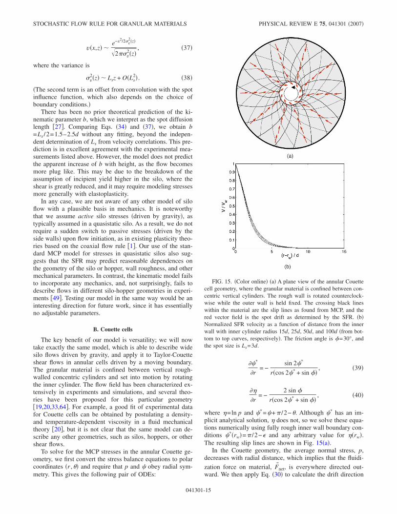
where �=ln p and �*=�+ /2−�. Although �* has an im-plicit analytical solution, � does not, so we solve these equa-tions numerically using fully rough inner wall boundary con-ditions �*�rw�= /2− and any arbitrary value for ��rw�.The resulting slip lines are shown in Fig. 15�a�.
In the Couette geometry, the average normal stress, p,decreases with radial distance, which implies that the fluidi-
zation force on material, F� net, is everywhere directed out-ward. We then apply Eq. �30� to calculate the drift direction
FIG. 15. �Color online� �a� A plane view of the annular Couettecell geometry, where the granular material is confined between con-centric vertical cylinders. The rough wall is rotated counterclock-wise while the outer wall is held fixed. The crossing black lineswithin the material are the slip lines as found from MCP, and thered vector field is the spot drift as determined by the SFR. �b�Normalized SFR velocity as a function of distance from the innerwall with inner cylinder radius 15d, 25d, 50d, and 100d �from bot-tom to top curves, respectively�. The friction angle is �=30°, andthe spot size is Ls=3d.
STOCHASTIC FLOW RULE FOR GRANULAR MATERIALS PHYSICAL REVIEW E 75, 041301 �2007�
041301-15
ds�r� by projecting the vector F� net onto slip lines, and imple-ment the SFR, exploiting symmetry which allows only a
nonzero velocity in the � direction. This implies
u* · r = 0 = − Ls�ds · r� s +Ls
2
2
� s
�r, �41�
which yields a solution for s up to a scalar factor. We thenuse s to calculate the � component of the �unconvolved�velocity once again using the SFR equation,
u* · � = − Ls�ds · �� s. �42�
It turns out, as we may have expected, that u* has a shearband at the inner wall with nearly exact exponential decay.The length scale of this decay is the spot size, Ls, since thisis the velocity correlation length, beyond which the inadmis-sible shear at the inner cylinder can be effectively dissipatedby the material.
The thinness of the shear band requires that, for consis-tency, we must take into account the finite spot size in recon-structing the velocity field through the convolution integral�27�. For simplicity we will use a uniform spot influencefunction, i.e.,
w�r� =4
Ls2H�Ls
2− �r� , �43�
where H�x� is the Heaviside step function. To evaluate theintegral �27�, we also must make a hypothesis about howspots operate when they overlap one of the walls. Randompacking dynamics near walls is different than in the bulk andsensitive to surface roughness, and further detailed analysisof experiments and simulations will be required to elucidatethe collective mechanism�s�. Here, the precise shape of spotsnear the wall has little effect, except to flatten out the spikein velocity that occurs near the wall in the unconvolved ve-locity u*. As a simple first approximation, used hereafter inthis paper, we will view the space beyond each boundary ascontaining a bath of nondiffusive spots at uniform concen-tration whose flux is such that the particle velocity invoked“inside” the boundaries directly mimics the rigid motion ofthe walls. This effectively “folds” part of the spot influenceback into the granular material when it overlaps with thewall. The resulting velocity field is shown in Fig. 15�b�,where normalized velocity is shown versus distance from theinner cylinder wall for Ls=3d for a wide range of inner cyl-inder radii.
The predicted flow field—without any fitting—is in strik-ing agreement with a large set of data from experimental anddiscrete-element simulations for different cylinder radii andgrain sizes �19,33,64,66�. As shown in Figure 16, the experi-mental data compiled by GDR Midi �33� falls almost entirelywithin the predicted SFR velocity profiles, by setting the spotsize to the same typical range of correlation lengths, Ls=3−5d, measured independently in a quasi-2D silo �Fig. 11�.Viewing the data on a semilog plot shows that the agreementextends all the way into the tail of the velocity distribution.We emphasize that the same simple theory, with the samerange of Ls values, also accurately predicts silo flows above,
as well as other situations below. Unifying all of this data ina single simple theory without any empirical fitting consti-tutes a stringent quantitative test.
It is interesting to note the behavior close to the wall,especially in thin Couette cells. In experiments �33�, annularflow profiles are known to have a Gaussian correction termwhen the thickness of the cell becomes non-negligible interms of particle size. This slight flattening near the wall isapparent in our model as well and is a by-product of con-volving with the spot influence. We thus interpret this featureas another sign of the strongly correlated motion of particles,primarily with the “cage” of nearest neighbors, as approxi-mately described by the spot mechanism. In this calculation,we used a uniform spot influence, but have noticed relatively
FIG. 16. �Color online� Theory versus experiment for the nor-malized velocity in annular Couette cells on �a� linear and �b� semi-log plots. The dashed curve is the predicted SFR velocity field withLs=3d, while the solid line is for Ls=5d; both curves are for aninner cylinder radius of rw=80d and �=30°. Experimental mea-surements �points� for a wide range of inner and outer cylinder radiiare shown from the compilation of data shown in Fig. 3c of �33�.�The experimental data is courtesy of Midi and originates from thework of �65–68�.�
KEN KAMRIN AND MARTIN Z. BAZANT PHYSICAL REVIEW E 75, 041301 �2007�
041301-16
little sensitivity of the predicted flow profile, for differentstrongly localized influence functions, such as a Gaussian,
w�e−2r2/Ls2. A detailed comparison of the model to experi-
mental data may provide fundamental insights into the spotinfluence, and thus the collective dynamics of random pack-ings, near a rough wall at the discrete particle level.
The experimental results shown in Fig. 16 come fromapparati with inner wall radii ranging from 14d−100d. Therelatively small variations in the data sets over such a largerange of inner radii clearly indicates that the inner wall ra-dius is not a crucial length scale in the flow. The plottedtheoretical prediction uses an inner radius of 80d, but, ascan be seen in Fig. 15�b�, our results depend only minimallyon the inner cylinder radius. Indeed, the mesoscale correla-tion length of Ls=3−5d is the dominant length scale in ourtheory for this geometry.
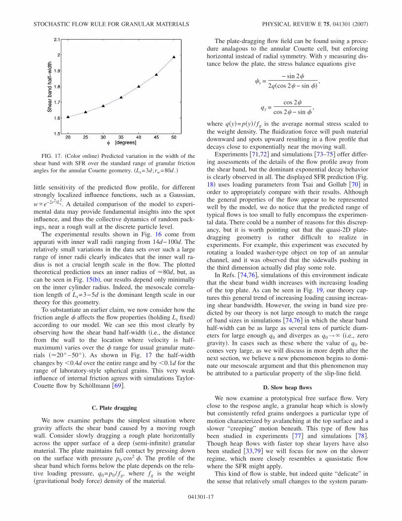
To substantiate an earlier claim, we now consider how thefriction angle � affects the flow properties �holding Ls fixed�according to our model. We can see this most clearly byobserving how the shear band half-width �i.e., the distancefrom the wall to the location where velocity is half-maximum� varies over the � range for usual granular mate-rials �20° –50° �. As shown in Fig. 17 the half-widthchanges by �0.4d over the entire range and by �0.1d for therange of laboratory-style spherical grains. This very weakinfluence of internal friction agrees with simulations Taylor-Couette flow by Schöllmann �69�.
C. Plate dragging
We now examine perhaps the simplest situation wheregravity affects the shear band caused by a moving roughwall. Consider slowly dragging a rough plate horizontallyacross the upper surface of a deep �semi-infinite� granularmaterial. The plate maintains full contact by pressing downon the surface with pressure p0 cos2 �. The profile of theshear band which forms below the plate depends on the rela-tive loading pressure, q0= p0 / fg, where fg is the weight�gravitational body force� density of the material.
The plate-dragging flow field can be found using a proce-dure analagous to the annular Couette cell, but enforcinghorizontal instead of radial symmetry. With y measuring dis-tance below the plate, the stress balance equations give
�y =− sin 2�
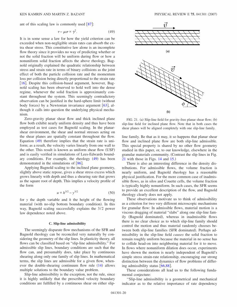
2q�cos 2� − sin ��,
qy =cos 2�
cos 2� − sin �,
where q�y�= p�y� / fg is the average normal stress scaled tothe weight density. The fluidization force will push materialdownward and spots upward resulting in a flow profile thatdecays close to exponentially near the moving wall.
Experiments �71,72� and simulations �73–75� offer differ-ing assessments of the details of the flow profile away fromthe shear band, but the dominant exponential decay behavioris clearly observed in all. The displayed SFR prediction �Fig.18� uses loading parameters from Tsai and Gollub �70� inorder to appropriately compare with their results. Althoughthe general properties of the flow appear to be representedwell by the model, we do notice that the predicted range oftypical flows is too small to fully encompass the experimen-tal data. There could be a number of reasons for this discrep-ancy, but it is worth pointing out that the quasi-2D plate-dragging geometry is rather difficult to realize inexperiments. For example, this experiment was executed byrotating a loaded washer-type object on top of an annularchannel, and it was observed that the sidewalls pushing inthe third dimension actually did play some role.
In Refs. �74,76�, simulations of this environment indicatethat the shear band width increases with increasing loadingof the top plate. As can be seen in Fig. 19, our theory cap-tures this general trend of increasing loading causing increas-ing shear bandwidth. However, the swing in band size pre-dicted by our theory is not large enough to match the rangeof band sizes in simulations �74,76� in which the shear bandhalf-width can be as large as several tens of particle diam-eters for large enough q0 and diverges as q0→� �i.e., zerogravity�. In cases such as these where the value of q0 be-comes very large, as we will discuss in more depth after thenext section, we believe a new phenomenon begins to domi-nate our mesoscale argument and that this phenomenon maybe attributed to a particular property of the slip-line field.
D. Slow heap flows
We now examine a prototypical free surface flow. Veryclose to the respose angle, a granular heap which is slowlybut consistently refed grains undergoes a particular type ofmotion characterized by avalanching at the top surface and aslower “creeping” motion beneath. This type of flow hasbeen studied in experiments �77� and simulations �78�.Though heap flows with faster top shear layers have alsobeen studied �33,79� we will focus for now on the slowerregime, which more closely resembles a quasistatic flowwhere the SFR might apply.
This kind of flow is stable, but indeed quite “delicate” inthe sense that relatively small changes to the system param-
FIG. 17. �Color online� Predicted variation in the width of theshear band with SFR over the standard range of granular frictionangles for the annular Couette geometry. �Ls=3d ;rw=80d . �
STOCHASTIC FLOW RULE FOR GRANULAR MATERIALS PHYSICAL REVIEW E 75, 041301 �2007�
041301-17
eters �i.e., flow rate, height of the flowing layer� can invokelarge changes to the qualitative flow profile especially in thetop layers �78�. We will describe and attempt to explain thiseffect more in the next section.
The heap geometry is depicted in Fig. 20 along with thecorresponding spot drift field and slip-line field. Any gravitydriven free surface flow problem for which the stresses andflow are approximately invariant in the direction parallel tothe surface will have limit-state stresses that obey the follow-ing relations:
� = − , �44�
p =fgy
cos �, �45�
where y is the depth measured orthogonally from the freesurface. Note that in limit-state theory, for self-consistency,the static angle of repose is identical to the internal frictionangle �, which is a reasonable assertion but still debated inthe community. �By “static repose angle” we refer to theangle of inclination below which a flowing system jams; insimulations of flow down a rough inclined plane, it has beenshown that this angle does vary in a narrow range dependingon the height of the flow �78,80�.� Applying Eq. �30� to theseequations gives a simple expression for the spot drift vector:
ds =�1 + sin2 �,− sin � cos ����1 + sin2 �,− sin � cos ���
. �46�
We may then apply the SFR, which simplifies upon requiringthat the flow run parallel to the free surface �i.e., u*= �−u ,0��.
Since the drift field is uniform, we obtain an analyticalsolution for the unconvolved velocity:
u = u�0�exp�− y sin 2�
Ls
� 2
5 − 3 cos 2� . �47�
Thus our model predicts that the velocity decays exponen-tially off the free surface. In cases like these, where theboundary of the flow makes no contact with a rigid wall, it isless clear how the spots �and free volume� might behave near
FIG. 18. �Color online� �a� The plate-dragging geometry. Thetop wall drags along the top of a bed of granular material. Thecrossing black lines within the material are the slip lines as foundfrom MCP, and the vector field is the spot drift as determined by theSFR. �b� Theory against experiment for the plate dragging geom-etry. Theory: L=3 �---�; L=5 �—�. Experiment ��� courtesy of theauthors of �70�.
FIG. 19. �Color online� Plot of theoretical shear band half-widthvs relative loading pressure q0= p�y=0� / fg of the top plate �wherefg is the weight density�. The calculation assumes Ls=5d.
KEN KAMRIN AND MARTIN Z. BAZANT PHYSICAL REVIEW E 75, 041301 �2007�
041301-18
the flowing free surface. To avoid addressing this issue indetail, we neglect convolution with the spot influence func-tion and simply assume uu*.
In their experiments on slow heap flow, Lemieux andDurian �77� have shown that the velocity profile in the flow-ing top layers is indeed well approximated by an exponentialdecay. Furthermore, they found the flow in this regime to becontinuous and stable. The decay law they obtained is
u/u�0� exp�−y
4.5d ,
which is very close to our predicted solution for Ls=3d:
u/u�0� = exp�−y
4.58d .
Silbert et al. �78� report finding a similar decay profile at lowflow rates in simulations of flow down a rough inclinedplane, although the avalanching at the surface was intermit-tent. Komatsu et al. �79� have conducted faster heap flowexperiments �discussed below in more detail� and found anexponentially decaying region of much smaller decay length,1.4d, beneath the rapid flowing top layer �see Fig. 23�. We
note that this flow is qualitatively different than the slowerheap flows we attempt to describe here in which the decaybehavior persists to the surface and is measured in the toplayers. In conclusion, we have demonstrated a fourth, quali-tatively different situation where the same simple MCP-SFRtheory predicts the flow profile, without adjusting any param-eters.
VI. TRANSITION FROM THE SFR TO BAGNOLDRHEOLOGY
A. Breakdown of the SFR
In the last two examples, plate dragging and slow heapflow, there are limits where the SFR fails to predict the ex-perimental flow profiles. In this section, we will explain whythe breakdown of the SFR is to be expected in these casesand others, whenever slip lines approach “admissibility” andcoincide with shear planes. In this singular limit of the SFR,we postulate a transition to Bagnold rheology. The stochasticspot-based mechanism for plastic yielding is thus replacedby a different physical mechanism, the free sliding alongshear planes.
For example, consider the case of plate dragging above.At large relative loading, the flow field resembles that of azero-gravity horizontal shear cell �between shearing flatplates�, and it appears that the SFR breaks down: With body
forces and �p both going to 0, Eq. �30� gives F� net=0 imply-ing that spots have no drift and consequently the only SFRsolution is u=0.
Problems also occur with flow down a rough inclinedplane: Slightly increasing the flow rate �and consequently theflow height� or inclination angle causes the velocity vs depthrelationship to exit the exponential decay regime detailedabove and undergo significant changes, passing first througha regime of linear dependence �81,82� to a regime resem-bling a 3/2 power-law of depth �80,83–85� opposite in con-cavity to the exponential decay regime.
Why does the velocity profile for inclined plane flow un-dergo many different qualitative regimes depending deli-cately on system parameters, while others �e.g., silos, annularcells� appear to be only weakly affected and almost alwaysexhibit the same �normalized� velocity profile? Tall inclinedplane flows and zero-gravity planar shear flows have beensuccessfully described in multiple experiments and simula-tions �63,80,83,84,86� by the empirical scaling law of Bag-nold �16�. In this section, we suggest a means to reconcileand perhaps eventually combine these theories into a coher-ent whole.
B. Bagnold rheology
Let us briefly review Bagnold’s classical theory of granu-lar shear flow. In its original form, “Bagnold scaling” ex-presses a particular rate dependency for granular flow when-ever the solid fraction is uniform throughout:
� � �2. �48�
where � is the rate of simple shear. To account as well forstatic stresses arising from the internal friction, a related vari-
FIG. 20. �Color online� �a� The heap flow setup. �b� The dashedrectangle in �a� is enlarged; the slip-line field from MCP is plottedalong with the drift field from the SFR.
STOCHASTIC FLOW RULE FOR GRANULAR MATERIALS PHYSICAL REVIEW E 75, 041301 �2007�
041301-19
ant of this scaling law is commonly used �87�:
� − �� � �2. �49�
It is in some sense a law for how the yield criterion can beexceeded when non-negligible strain rates can absorb the ex-tra shear stress. This constitutive law alone is an incompleteflow theory since it provides no way of predicting whether ornot the solid fraction will be uniform during flow or how anonuniform solid fraction affects the above rheology. Bag-nold originally explained the quadratic relationship betweenstress and strain rate in terms of binary collisions as the jointeffect of both the particle collision rate and the momentumloss per collision being directly proportional to the strain rate�16�. Despite this collision-based argument, however, Bag-nold scaling has been observed to hold well into the denseregime, whenever the solid fraction is approximately con-stant throughout the system. This seemingly contradictoryobservation can be justified in the hard-sphere limit �withoutbody forces� by a Newtonian invariance argument �63�, al-though it calls into question the underlying physical mecha-nism.
Zero-gravity planar shear flow and thick inclined planeflow both exhibit nearly uniform density and thus have beenemployed as test cases for Bagnold scaling. In the planar-shear environment, the shear and normal stresses acting onthe shear planes are spatially constant throughout the flow.Equation �49� therefore implies that the strain rate is uni-form; as a result, the velocity varies linearly from one wall tothe other. This result is known as uniform shear flow �USF�and is easily verified in simulations of Lees-Edwards bound-ary conditions. For example, the rheology �49� has beendemonstrated in the simulations of �86�.
Applying Bagnold scaling to the inclined plane geometry,slightly above static repose, gives a shear stress excess whichgrows linearly with depth and thus a shearing rate that growsas the square root of depth. This implies a velocity profile ofthe form
u � h3/2 − y3/2 �50�
for y the depth variable and h the height of the flowingmaterial �with no-slip bottom boundary condition�. In thisway, Bagnold scaling successfully explains the 3/2 powerlaw dependence noted above.
C. Slip-line admissibility
The seemingly disparate flow mechanisms of the SFR andBagnold rheology can be reconciled very naturally by con-sidering the geometry of the slip lines. In plasticity theory, allflows can be classified based on “slip-line admissibility.” Foradmissible slip lines, boundary conditions are such that theflow can, and presumably does, take place by continuousshearing along only one family of slip lines. In mathematicalterms, the slip lines are admissible for a given flow, when-ever the double-shearing continuum flow rule �14� allowsmultiple solutions to the boundary value problem.
Slip-line admissibility is the exception, not the rule, sinceit is highly unlikely that the prescribed velocity boundaryconditions are fulfilled by a continuous shear on either slip-
line family. Be that as it may, it so happens that planar shearflow and inclined plane flow are both slip-line admissible.This special property is shared by no other flow geometrystudied in this paper, or, to our knowledge, elsewhere in thegranular materials community. �Contrast the slip lines in Fig.21 with those in Figs. 14 and 15.�
There is also an interesting difference in the density dis-tributions. For admissible flows, the volume fraction isnearly uniform, and Bagnold rheology has a reasonablephysical justification. For the more common case of inadmis-sible flows, as in silos and Couette cells, the volume fractionis typically highly nonuniform. In such cases, the SFR seemsto provide an excellent description of the flow, and Bagnoldrheology clearly does not apply.
These observations motivate us to think of admissibilityas a criterion for two very different microscopic mechanismsfor granular flow: In admissible flows, material motion is aviscous dragging of material “slabs” along one slip-line fam-ily �Bagnold dominated�, whereas in inadmissible flowsthere is no clear choice as to which slip-line family shouldcontrol the motion and thus material randomly chooses be-tween both slip-line families �SFR dominated�. Perhaps ad-missibility in the slip-line field causes the solid fraction toremain roughly uniform because the material in no sense hasto collide head-on into neighboring material for it to move.In flows where nonuniform dilation does occur, experimentshave shown the motion is nearly independent of Bagnold’ssimple stress strain-rate relationship, encouraging our strongdistinction between the dynamics of flow problems of differ-ing admissibility status �66,88�.
These considerations all lead us to the following funda-mental conjecture:
‘‘Slip-line admissibility is a geometrical and mechanicalindicator as to the relative importance of rate dependency
FIG. 21. �a� Slip-line field for gravity-free planar shear flow; �b�slip-line field for inclined plane flow. Note that in both cases theshear planes will be aligned completely with one slip-line family.
KEN KAMRIN AND MARTIN Z. BAZANT PHYSICAL REVIEW E 75, 041301 �2007�
041301-20
�Bagnold rheology� over rate independency �SFR� in a densegranular flow.’’
This means that a flow which has an admissible limit-statestress field will be dominated by rate-dependent effects whenthe yield criterion is only slightly exceeded.
D. Redistribution of excess shear stress
A more rigoruous physical justification of our conjecturecan be made utilizing limit-state stresses and observing theeffect of pushing the system above yield. Bagnold rheologyis a statement connecting the shear stress excess �i.e., amountby which � exceeds ��� along a shear plane to the rate ofsimple shear along the plane. We must emphasize that shearplanes and slip lines are not equivalent terms; slip lines aredefined by the quasistatic stresses as lines along which �−��=0, whereas shear planes are defined entirely by thevelocity profile. In an admissible system, the shear planescoincide with one slip-line family. In inadmissible systems,the shear planes almost everywhere do not coincide with sliplines.
With admissible slip lines, excess shear stress tends to beuniformly distributed throughout the system, resulting in glo-bal Bagnold rheology. For example, consider a zero-gravityplanar shear cell. If we were to apply additional shear stressto the body in a manner aligned with the admissible slip-linefamily, e.g., by increasing the wall shear stress above yieldby some amount ��, that additional shear stress would dis-tribute itself within the material precisely along the slip lines.Every horizontal slip line within the bulk would thus receivea boost in shear stress of size ��. In limit-state theory theslip lines have the highest possible �−�� value a quasistaticmaterial element can take—zero. Adding �� additonal shearstress to the slip lines means that � will maximally exceed�� precisely along the slip lines, and, by admissibility, everyshearing plane. As a result, there will be a Bagnold contri-bution everywhere. Similarly, if we took a limit-state in-clined plane geometry and increased the tilt angle someamount, an analagous boost in shear stress along the admis-sible slip-line family would occur causing � to exceed ��precisely along all the shear planes.
In contrast, with inadmissible slip lines, excess shearstress tends to remain localized where it is applied, and theSFR dominates the rest of the flow. For example, considerannular Couette flow. As can be seen in Fig. 15, the slip linesonly coincide with the shear planes �which in this case areconcentric circles� along the inner wall of the cell. If theinner wall were given an increase �� in applied shear stress,torque balancing requires the shear stress along any concen-tric circle within the material to receive a boost of �� ·rw /r.Suppose the shear cell has inner wall radius 40d and theboost in wall shear is significant, say ��=�w /10. Solving for�−�� along the shear planes in this situation gives a verydifferent result than in the previous case—here � will onlyexceed �� along the shear planes that are less than 1.4d offthe inner wall. So, regardless of whether the density is or isnot uniform, Bagnold scaling would at best only apply in analmost negligibly thin region near the wall. If the wall fric-tion were less than fully rough, this region would furtherdecrease.
E. Simple composite theory
The preceding discussion indicates that, in general, onecan use the admissibility status of the system to choosewhether or not the flow should obey the SFR or Bagnoldrheology, or perhaps some combination of the two. Indeed, itseems reasonable that when slip lines are approaching ad-missibility �e.g., plate-dragging with high q0� or when anadmissible system is only slightly pushed above yield �e.g.,inclined plane flow near static repose� we must account forcontributions from both effects simultaneously. It is beyondthe scope of this paper to postulate the precise microscopicdynamics �and derive corresponding continuum equations�for this regime, but we can at least give a sense of how themore general theory might look.
In general, we envision a smooth transition from rate-independent SFR dynamics to rate-dependent Bagnold dy-namics controlled by the distribution of shear stress excess.This implies the coexistence of �at least� two different mi-croscopic mechanisms: SFR and admissible shear. The SFRcontribution would derive from the usual spot-based, quasi-static stochastic dynamics; the Bagnold contribution wouldcome from a rate-dependent shearing motion along the ap-propriate slip-line family whenever there is a small excessshear stress �beyond the limit state� which causes shear stressexcess along the shear planes within.
The two mechanisms should have different statistical sig-natures. For shear deformation along admissible slip lines,we would expect anisotropic velocity correlations. In the di-rection perpendicular to the shear plane, the correlationlength should be somewhat shorter than the typical spot size,since slip-line admissibility allows flow to occur with lessdrastic local rearrangements, farther from jamming. In thedirections parallel to the shear plane, however the correlationlength could be longer, since material slabs sliding alongshear planes may develop more rigid, planar regions. Itwould certainly be interesting to study velocity correlationsin heap flows at different inclinations and plate-dragging ex-periments under different loads to shed more light on themicroscopic mechanisms involved in the SFR to Bagnoldtransition.
For the remainder of this section, we make a first attemptat a composite model, simply a linear superposition of SFRand Bagnold velocity fields:
u = �uSFR + �uBag, �51�
which could have its microscopic basis in a random compe-tition between the two mechanisms, when slip lines are nearadmissibility. Here, uSFR is an SFR solution for the flow,using the limit-state stress field everywhere, and uBag is ob-tained from the excess shear stress on a boundary by inte-grating the Bagnold strain rate �=��−�� over those shearplanes for which �−�� has been boosted above zero. �Notethat we ignore the condition of uniform density for Bagnoldrheology since we conjecture that uniform density is actuallya geometric consequence of slip-line admissibility and willarise naturally whenever Bagnold rheology dominates theflow.�
STOCHASTIC FLOW RULE FOR GRANULAR MATERIALS PHYSICAL REVIEW E 75, 041301 �2007�
041301-21
A reasonable first approximation is that the SFR and Bag-nold solutions individually fulfill the necessary boundaryconditions for the velocity profile since, under the right cir-cumstances, either can be made to dominate the other. Theconstant � is the Bagnold proportionality constant whichmay depend on the density of the flow among other param-eters �86�. Since the SFR is a rate-independent flow model,uSFR can always be multiplied by a positive constant �ob-serve that Eq. �26� is homogeneous in s�, and thus we allowthe scalar multiple �. Given some determinable form for �,� is chosen such that u fits the velocity boundary conditions.This seems reasonable for moving walls �as in plate drag-ging�, but not for free surfaces, whose boundary velocityshould also be predicted by the theory. In such cases, where� is not clearly defined in this simple model, one could useother empirical relations, such as the Pouliquen flow rule forinclined plane flows �83�, to deduce the free boundary veloc-ity, and thus �.
F. Some applications of the composite theory
Using our very simple composite theory, we will nowrevisit a few geometries that were troublesome for the SFRalone. Extending the theory with a smooth transition to Bag-nold scaling controlled by slip-line admissibility seems toresolve the experimental puzzles and capture the basic phys-ics of granular shear flows. In the cases we consider below,we do not change the value of � as we increase the shearstress excess; this way the relative importance of Bagnoldeffects are easier to isolate.
1. Planar shear cell
In a zero-gravity planar shear cell, uSFR=0, but the Bag-nold solution for any amount of shear stress excess is of theform uBag=ky, and thus the composite solution, regardless ofthe values � and �, is a homogeneous flow between the tworough plates. The lack of a “background” SFR solution inthis case may explain why Bagnold rheology is almost ex-actly observed in simulations of this geometry over a widerange of strain rates �63�.
2. Rough inclined plane
For flow down a rough inclined plane, the SFR solution isan exponential decay �47�, and the Bagnold solution is a 3/2power law �50�. When the material is only slightly abovestatic repose, a shear stress excess along the shear planes willexist but will be very small; it goes as ��� for an incline ��above static repose �87�. As a result, uBag will be small inmagnitude, and the SFR solution will show through as the“creeping flow” with exponential decay. As �� increases, theincreased shear stress excess will cause the Bagnold contri-bution to increase, and the flow will eventually morph intothe 3/2 power law dependence of pure Bagnold scaling. Inbetween, where both contributions are of similar magnitude,the superposition of the two flow fields gives a predictedprofile that appears approximately linear, since the SFR andBagnold solutions are of opposite concavity. Thus the com-posite SFR-Bagnold formulation appears to be able to ex-plain the various flow regimes in inclined plane flow, which
have been observed in experiments and simulations �see Fig.22�.
Recent experimental work of Pouliquen �89� seems tosupport this analysis; it is found that inclined plane flowoccurring at lower inclination angles exhibits spatial velocitycorrelations near the typical spot size �as the SFR wouldimply�, but as inclination increases, the correlation lengthappears to decrease, an effect we might attribute to an in-creased dominance of Bagnold scaling �a phenomenon notgoverened by a correlation length� over the SFR.
3. Rapid heap flows
The composite theory also seems consistent with rapidheap flows. When the flow rate down the heap increases, theregion near the surface resembles inclined plane flow in anyone of its various flow regimes, whereas the region beneaththe surface flow undergoes creep motion which decays closeto exponentially �33,79� �see Fig. 23�. We can justify this interms of slip-line admissibility: The slip lines throughout the
FIG. 22. �Color online� Some predicted velocity profiles forflow down a rough inclined plane as a function of depth. Note thatall three known flow behaviors, exp decay, linear, and 3/2 powerlaw, appear in proper relationship to the inclination �see Ref. �78��.�Bottom� Incline near static repose, fully SFR dominated �Ls=4d�.�Middle� Increased inclination angle, Bagnold to SFR ratio of 3:1.�Top� Further increase to inclination; fully Bagnold dominated.
FIG. 23. �Color online� Standard heap flows enable one to seeboth the SFR and Bagnold contributions separately in one flowgeometry. �a� The surface region is dominated by Bagnold scaling.�b� The creep region beneath adheres to the SFR.
KEN KAMRIN AND MARTIN Z. BAZANT PHYSICAL REVIEW E 75, 041301 �2007�
041301-22
system �see Fig. 21� have the same form in both regions. Inthe surface region, the slip lines are admissible because thereis nothing blocking the motion from being a simple shearingalong the slip lines. In the creep region, however, the gate �orthe ground� prevents global shearing along the slip lines andthus the slip lines are inadmissible and the SFR dominates.
We can equivalently explain heap flow in terms of shearstress excess. The excess incurred by increasing the heapangle will distribute itself differently in the two regions. Inthe surface region, the excess can only be absorbed along theshear planes by inducing a strong Bagnold dependence.However, the gate at the bottom of the heap will support anyshear stress excess on the creep region. �Note that the sliplines in the creep region all hit the gate, or the ground.� Thusthe full flow will be the sum of an exponentially decayingSFR solution superposed with a significant Bagnold-type so-lution which starts at the surface and cuts off at the interfacewith the creep zone.
4. Plate dragging under a heavy load
We will now explain the comment made at the end of theplate-dragging section. The slip lines of a plate-dragging ge-ometry can be pushed drastically close to full admissibilityby simply increasing the relative loading of the top plate, q0,above a certain nonexcessive amount �see Fig. 24�. To seethe effects of approaching admissibility more carefully, saywe take a limit-state plate-dragging setup and pull the plateslightly harder, inducing a superyield shear stress boost of�� under the plate. Bagnold effects should appear wherever,as a consequence of stress balancing, a shear stress excessresults along a shear plane. The shear planes are horizontallines in this case, and at limit state, the stresses along anyhorizontal obey
� − �� = − �fgy = − �p0
q0y . �52�
When the extra shear stress is applied, a shear stress excessof ��−�p0y /q0 will form for 0�y� ��� /�p0�q0. Accord-
ingly the Bagnold flow contribution will have a shear zonewhose depth extends into the granular bed as an increasinglinear function of q0 for a fixed shear stress boost �� andfixed downward plate pressure �i.e., we decrease the materialweight density to increase q0�. Integrating the Bagnold shearrate gives that the relative size of the Bagnold contributionshould also increase with increasing q0. With q0 largeenough, therefore, the SFR contribution will be dwarfed by aBagnold term with a larger shear band. As q0→� the sliplines become completely admissible and the shear bandwidth diverges as we would expect.
The mismatch in shear band size between the data of Tsaiand Gollub and the SFR could be due, among other possiblereasons, to the fact that q0380d was large enough to makethe Bagnold contributution sizeable. This could also explainthe large shear bands found in �74�. A detailed comparison ofexperiments and simulations with different versions of acomposite SFR-Bagnold theory would be an interested direc-tion for future work.
VII. CONCLUSION
A. Highlights of the present work
We have proposed a stochastic flow rule �SFR� for granu-lar materials, assuming limit-state stresses from Mohr-Coulomb plasticity �MCP�. In the usual case where slip linesare inadmissible �inconsistent with boundary conditions�, wepostulate that flow occurs in response to diffusing “spots” oflocal fluidization, which perform random walks along sliplines, biased by stress imbalances. The spot-based SFR cor-rects many shortcomings of classical MCP and allows someof the first reasonable flow profiles to be derived from limit-state stresses, which engineers have used for centuries todescribed the statics of granular materials.
Our theory notably differs from all prior continuum theo-ries �cited in the Introduction� in that it is derived systemati-cally from a microscopic statistical model �27�. The spotmodel is already known to produce realistic flowing randompackings �28�, and what we have done is to provide a generalmechanical theory of spot dynamics. Evidence for spots hasbeen consistently found in spatial velocity correlations insimulations �28� and experiments �57� �Fig. 11� on silo drain-age.
Beyond its fundamental physical appeal, the SFR seemsto have unprecedented versatility in describing differentgranular flows. It has only two parameters, the friction angle� and correlation length �spot size� Ls, which are not fitted;they are considered properties of the material which can bemeasured independently from flow profiles. For monodis-perse frictional spheres, the SFR can predict a variety ofdifferent flows using the same spatial velocity correlationlength, Ls3−5d, measured in experiments and simulations.This is perhaps the most compelling evidence in favor of thespot mechanism which underlies the SFR.
We have shown that the SFR can describe a rather diverseset of experimental data on granular flows. Some flows aredriven by body forces �silo and heap flows�; others havebody forces, but are driven by applied shear �plate dragging�;still others are driven by applied shear without body forces
STOCHASTIC FLOW RULE FOR GRANULAR MATERIALS PHYSICAL REVIEW E 75, 041301 �2007�
041301-23
�annular shear flow�. Some geometries have straight bound-aries �silos, heaps, plate dragging�, and yet the theory worksequally well for highly curved boundaries �annular shearflow�. Some of the flows exhibit shear localization �annularshear flow, plate dragging, heap flow�, and yet the theorycorrectly predicts wide shear zones in silo flow. It is note-worthy that the same, simple model, correctly predicts andplaces shear bands in geometries where they arise for verydifferent reasons—gravity causes the shear band in platedragging, and yet the geometry �through the �p term in thedrift� causes the shear band in annular Couette flow. We arenot aware of any other theory �including classical MCP�which can quantitatively describe more than one of theseflows, let alone without empirically fitting the velocity pro-files.
B. Comparison with partial fluidization
It is interesting to compare our approach to the continuumtheory of partial fluidization of Aranson and Tsimring�31,32�. Although it lacks any microscopic basis, their theoryalso introduces a diffusing scalar field to control the dynam-ics, as opposed to a classical stress–strain-rate relation. Theanalog of our spot density is the “order parameter” , whichmeasures the degree of “fluidization” of the continuum bymixing two different types of stresses, corresponding to dis-tinct “liquid” � =0� and “solid” � =1� phases. Given thestress tensor for the material in a static solid state, �ij
0 , thestresses in a flowing granular material are modeled by addingsome degree of viscous stresses, as in a Newtonian liquid:
�ij = � + �1 − ��ij��ij0 + �Eij , �53�
where � is the viscosity. The order parameter controlling thebalance of these two stress tensors is postulated to obey areaction-diffusion equation,
��t��
�t= l2�2 + �1 − �� − �� �54�
for collision time �t, grain length scale l, and a function � ofthe stress state, which is greater than 1 where the material isabove the static yield criterion, less than 0 where below thedynamic yield criterion, and between 0 and 1 otherwise. Onebenefit of this model is that it can be used for unsteady flows.In principle, the SFR may also describe time dependencethrough the spot Fokker-Planck equation �24�, but we haveonly developed and tested the theory so far for steady flows,starting from Eq. �26�.
For the sake of comparison, consider a steady flow mod-eled by partial fluidization and the SFR. The difference isthat the spot equation �26� couples diffusion to a drift de-pending on frictional yielding, whereas the order parameterequation �54� balances diffusion with a nonlinear sourceterm, ressembling a chemical reaction rate, which indirectlymimicks the effect of a Coulomb yield criterion. Interest-ingly, if the SFR could be extended to an elastoplastic modelwithout making the incipient failure assumption �see below�,a similar nonlinear source term may have to be added to thespot equation to account for the need to destroy �and create�
spots when they enter zones below �or closer to� yield. Moregenerally, a reaction term could describe the creation anddestruction of spots, e.g., in response to plastic work as in thetheory of shear transformation zones �90�.
As a higher-order yield effect, this term could also bechosen to reflect bistability in granular materials, where sol-idlike and fluidlike local phases can both be dynamicallystable and coexist depending on the stress state. Equation�54� describes this through the dependence of � on both �and �k and implies that stable flow can occur beneath thestatic yield criterion as long as the nearby kinetic yield cri-terion is still exceeded, as should be expected. Our currentmodel describes the case where static incipient failure andthe transition �→�k are both valid assertions, so it is effec-tively a flow theory more than a complete dynamic theory ofboth flow and solidification. To increase the prominence of�k would not just modify our flow rule, but also necessitate amore complicated stress model, given our physical hypoth-eses. Unsteady flows, such as a traveling avalanche front,may require accounting for bistability, but for fully devel-oped steady flows as described above there is often somedegree of motion, even in nearly stagnant regions. In anycase, solidlike regions do not seem to greatly affect the flowswe consider above. We should also point out that the SFRdoes allow a global no-flow solution since s=0 alwayssolves the spot equation.
It is also notable that our argument for why a spot drifts,i.e., a localized stick-slip type of shear stress decrease alongthe spot boundary, is reminiscent of Eq. �53� wherein thestatic shear stress goes down in the presence of fluidization.In this sense, a higher spot concentration in our model issimilar to a higher degree of partial fluidization.
One difficulty with the partial fluidization approach is thatit cannot easily describe rate-independent effects since themotion stems from a viscous form in the stress tensor. Alsoin sharp contrast to our approach based on plasticity, partialfluidization does not provide a clear theory of the static solidstresses in the limit of no flow, opting instead to deal withenvironments for which the open components of this tensorare not needed �simple shear flows�. This could perhaps bemodified. These considerations as well as selecting boundaryconditions on the order parameter, seem to be the primarylimitations in testing partial fluidization in more general situ-ations.
C. Future directions
In spite of some successes, we still do not have a com-plete theory of dense granular flow. There are at least threebasic limitations of the SFR, about which we can only offersome preliminary ideas to guide future work.
1. Slip-line inadmissibility
Although most slip-line fields are inadmissible, the SFRbreaks down as slip lines approach admissibility. We havealready begun to extend the model into this regime by con-jecturing that slip-line admissibility is associated with Bag-nold rheology, as excess shear stress �above the limit state�drives a local shear rate along the most admissible slip lines.
KEN KAMRIN AND MARTIN Z. BAZANT PHYSICAL REVIEW E 75, 041301 �2007�
041301-24
We have shown that a simple linear superposition of Bagnoldand SFR flow fields with appropriate boundary conditionscan describe a variety of composite flows, exhibiting bothBagnold and SFR behavior in different limits or segregatedinto different regions. These include planar zero-gravityshear, various inclined-plane and heap flows, and plate drag-ging at large loading. However, more work is needed to de-velop and test a composite SFR-Bagnold theory, both at thecontinuum level and in terms of the two microscopic mecha-nisms.
2. 2D symmetry
Through MCP, the SFR is currently used only in quasi-2Dgeometries. In efforts to extend the theory to 3D, a good testcase would be the split-bottom Couette cell, which displays awide, diffusive shear band �55�, reminscent of a drainingsilo. The 2D limitation may not be so difficult to overcome,although any plasticity theory is more complicated in threedimensions, than in two. As usual, constructing a 3D limit-state stress field requires an additional hypothesis to close thestress equations. In 3D, a general material point at incipientfailure with distinct principal stresses �1��2��3 is inter-sected by a pair of slip planes angled 2 apart. We cannottherefore encase a 3D cell of material within slip planes aswe are able to do to a 2D cell with slip lines. However, theprincipal plane on which �2 acts, the intermediate principalplane, can be used along with the slip planes to encase a 3Dmaterial cell. �See Fig. 25.� This is legitimate because, ifsuch a cell underwent slip-plane fluidization, the net materialforce would be guaranteed to point parallel to the intermedi-ate principal plane; since the intermediate principal planeoffers no shear resistance, the material can slide along thisplane, while simultaneously sliding along a slip plane.
To apply the SFR then, the drift vector should still becalculated from Eqs. �28� and �30�, but all vectors must beprojected first into the �1�3 plane since the �2 direction isnot involved in slip-plane fluidization. The shape of a spotand its diffusivity would likely be anisotropic, with differentvalues in the intermediate direction, since the main source ofdiffusion is slip-plane fluidization. �See Fig. 25.�
If ever the intermediate principal stress equals either themajor or minor principal stress, as in the Har Von Karmanhypothesis, incipient failure is upheld on a cone instead ofintersecting slip planes. When this degenerate case occurs,the material cell can be encased serveral different ways de-pending on the surrounding stress states. This must be deter-mined before we can rigorously define how to apply fluidi-zation and the SFR.
3. Incipient yield everywhere
The SFR assumes stresses near a limit state. While incipi-ent yield is believed to be a good hypothesis in many situa-tions, even during dense flow �which should be checked fur-ther in DEM simulations�, it clearly breaks down in somecases, at least in certain regions. This is perhaps the mostdifficult limitation to overcome, since the limit-state assump-tion is needed to fully determine the stress tensor. Without it,the material effectively enters a different state most likelygoverned by some nonlinear elastic stress strain law which isfar more difficult to apply.
We have already argued that such a transition away fromincipient yield must exist in some granular flows, due to thestrong tendency of granular materials to compactify into arigid solid state when shaken �e.g., by nearby flowing re-gions� but not sufficiently sheared. A good example is a tallnarrow silo with smooth side walls, where the SFR holdsnear the orifice, but breaks down in the upper region, ressem-bling a vertical chute. The broad shear band localizes on theside walls, as a rigid central plug develops, which likely fallsbelow incipient yield.
A more robust elastoplastic theory for the stress statewould relax our limit-state constraints and allow for materialto fall below the yield criterion where it is described byelasticity. The SFR could then be applied only where thematerial is at yield and everywhere else the material does notdeform plastically. Elastoplasticity theory operates just aswell in 3D as in 2D which is a key benefit over limit-stateplasticity. However, our model as we have already presentedit is far simpler than elastoplasticity and yet still managesaccurate results when applied to limit-state stress fields.
As the SFR matures as a theory of granular flow, it wouldalso be interesting to apply it to other amorphous materials,such as metallic glasses, and to develop new simulationmethods. The basic idea is very general and applies to anymaterial with a yield criterion. It has already been suggestedthat the spot model could have relevance for glassy relax-ation �27�, and the SFR provides a general means to drivespot dynamics, based on solid mechanical principles. Thespot model also provides a multiscale algorithm for random-packing dynamics, which works well for silo drainage �28�,so the SFR could enable a general framework for multiscalemodeling of amorphous materials. The idea would be tocycle between continuum stress calculations, mesoscale spotrandom walks, and microscopic particle dynamics.
ACKNOWLEDGMENTS
The authors are gratefully indebted to the many research-ers noted within who made their experimental data availablefor comparison with the present theory. Special thanks go tothe members of GDR Midi �especially Olivier Pouliquen�and to J.-C. Tsai for their help in the transferring of data. Theauthors also thank Zdeněk P. Bažant for helpful commentson the manuscript, and Pierre Gremaud for providing Fig. 7.
APPENDIX: CRITICAL STATE SOIL MECHANICS
A common precept in plasticity is the notion of normalityor associatedness. Flows that obey normality have a flow
FIG. 25. �Color online� The difference between 2D and 3D con-tinuum cells which could be used to construct the SFR.
STOCHASTIC FLOW RULE FOR GRANULAR MATERIALS PHYSICAL REVIEW E 75, 041301 �2007�
041301-25
rule defined in terms of the yield function Y as follows:
E = ��Y
�T, �A1�
where � is a positive multiplier. For a 3D flow, this meansthat if the yield function were plotted in six-space as a func-tion of all 6 independent entries in the 3D stress tensor, thestrain-rate matrix would be a “vector” pointing normal to theyield surface oriented toward greater values of Y.
One of the first gripes about the use of friction-based yieldcriteria in describing granular materials is that the principleof normality gives a flow rule that predicts unstoppable dila-tancy. Consider a rough extension of the Coulomb yield cri-terion into 3D, Y =��trT� /3+ �T0� /�2, which displays the ba-sic property that yield occurs when a certain multiple of thepressure equals the shear stress. Its associated flow rule is
E = �� T0
�2�T0�+
�
3I .
The trace of this strain-rate tensor is ��, implying that ma-terial undergoing plastic flow will never stop dilating.
Roscoe and co-workers �91� present a different viewpointon the issue. In what became known as critical state soilmechanics, explained in detail in �39�, they argue that nor-mality does hold, but that in fact the Coulomb yield criterionis not technically the correct yield function.
Backed by results from triaxial stress experiments on soilsamples, critical state theory claims that soils have a yieldfunction that depends on the soil consolidation as measuredby the local density . The yield curve for material at aparticular density is defined in terms of two stress tensorinvariants: the pressure p=− 1
3 trT and the equivalent shearstress q= �T0� /�2. Plotted in these variables, the principle of
normality is equivalent to the statement that the strain-ratevector � , �� is normal to the yield curve and pointing out-
ward, where =−trE is a volumetric strain-rate which deter-mines changes in density, and �= ��2/3��E0� is a shear strainrate proportional to the total shear deformation �volume-conserving part of the deformation�. Figure 26 displays thetheory’s picture of the yield function and how it changesafter material deformation. Any stress state underneath theyield curve corrresponds to rigid material. Under normality,material at point 1 in the initial state will undergo a defor-mation according to the vector �1 , �1�. Since 1 is negative,the material will dilate and settle down at point 1 on the righton a new yield curve corresponding to B� . The materialat stress state 2 will likewise undergo compaction and arriveat point 2 on the yield curve corresponding to A� .
The critical state line is defined as the locus of points forwhich normality predicts no volumetric changes duringdeformation—note that wherever a yield curve intersects thecritical state line, the curve becomes parallel to the p axis,and thus the corresponding strain-rate vector has no volumet-ric component. The theory reasons that the critical state lineis indeed a straight line of the form
q = Mp .
As flow develops, the stress states throughout the materialwill continually move toward the critical state line and oncelocal volume changes finally stop, all flowing material stressstates should lie on the critical state line. Thus in a steadyflow, the critical state line might falsely appear to be theyield function when in fact it is only a locus of states from afamily of yield functions. So, it is argued then that the reasonnormality previously failed to describe granular materialswas because it was applied mistakenly to the critical stateline and not to the true family of yield functions.
�1� R. M. Nedderman, Statics and Kinematics of Granular Mate-rials �Cambridge University Press, Cambridge 1992�.
�2� V. V. Sokolovskii, Statics of Granular Materials �Pergamon/Oxford, New York, 1965�.
�3� R. Hill, The Mathematical Theory of Plasticity �Oxford at theClarendon Press, New York, 1950�.
�4� H. M. Jaeger, S. R. Nagel, and R. P. Behringer, Rev. Mod.Phys. 68, 1259 �1996�.
�5� P. G. de Gennes, Rev. Mod. Phys. 71, S374 �1999�.�6� L. P. Kadanoff, Rev. Mod. Phys. 71, 435 �1999�.�7� S. F. Edwards and D. V. Grinev, Adv. Complex Syst. 4, 451
�2001� �also reprinted in Ref. �8��.�8� Challenges in Granular Physics, edited by T. Halsey and A.
Mehta �World Scientific, Singapore, 2002�.�9� I. S. Aranson and L. S. Tsimring, Rev. Mod. Phys. 78, 641
�2006�.�10� C. S. Campbell, Annu. Rev. Fluid Mech. 22, 57 �1990�.�11� N. Balmforth and A. Provenzale, Geomorphical Fluid Me-
chanics �Springer, New York, 2001�.�12� J.-P. Bouchaud, M. E. Cates, J. R. Prakash, and S. F. Edwards,
J. Phys. I 4, 1383 �1994�.�13� J.-P. Bouchaud, M. E. Cates, J. R. Prakash, and S. F. Edwards,
Phys. Rev. Lett. 74, 1982 �1995�.�14� T. Boutreux, E. Raphaël, and P.-G. de Gennes, Phys. Rev. E
58, 4692 �1998�.�15� T. Boutreux, H. A. Makse, and P.-G. de Gennes, Eur. Phys. J. B
FIG. 26. �Color online� �Left� Critical statetheory’s spade-shaped yield function for materialat some density . �Right� Deformations withnonzero volumetric strain will cause the materialto settle down on a new yield function.
KEN KAMRIN AND MARTIN Z. BAZANT PHYSICAL REVIEW E 75, 041301 �2007�
041301-26
9, 105 �1999�.�16� R. A. Bagnold, Proc. R. Soc. London, Ser. A 225, 49 �1954�.�17� D. Ertaş and T. C. Halsey, Europhys. Lett. 60, 931 �2002�.�18� S. B. Savage, J. Fluid Mech. 377, 1 �1998�.�19� W. Losert, L. Bocquet, T. C. Lubensky, and J. P. Gollub, Phys.
Rev. Lett. 85, 1428 �2000�.�20� L. Bocquet, W. Losert, D. Schalk, T. C. Lubensky, and J. P.
Gollub, Phys. Rev. E 65, 011307 �2002�.�21� P. Mills, D. Loggia, and M. Tixier, Europhys. Lett. 45, 733
�1999�.�22� O. Pouliquen and R. Gutfraind, Phys. Rev. E 53, 552 �1996�.�23� O. Pouliquen, Y. Forterre, and S. L. Dizes, Adv. Complex Syst.
4, 441 �2001� �also reprinted in Ref. �8��.�24� J. Litwiniszyn, Rheol. Acta 2/3, 146 �1958�.�25� J. Mullins, J. Appl. Phys. 43, 665 �1972�.�26� R. M. Nedderman and U. Tüzün, Powder Technol. 22, 243
�1979�.�27� M. Z. Bazant, Mech. Mater. 38, 717 �2006�.�28� C. H. Rycroft, M. Z. Bazant, G. S. Grest, and J. W. Landry,
Phys. Rev. E 73, 051306 �2006�.�29� A. Lemaître, Phys. Rev. Lett. 89, 195503 �2002�.�30� A. Lemaître, Phys. Rev. Lett. 89, 064303 �2002�.�31� I. S. Aranson and L. S. Tsimring, Phys. Rev. E 64, 020301�R�
�2001�.�32� I. S. Aranson and L. S. Tsimring, Phys. Rev. E 65, 061303
�2002�.�33� G. D. R. Midi, Eur. Phys. J. E 14, 341 �2004�.�34� M. Ostoja-Starzewski, Int. J. Plast. 21, 1119 �2005�.�35� W. Prager and D. C. Drucker, Q. Appl. Math. 10:2, 157
�1952�.�36� R. M. Horne and R. M. Nedderman, Powder Technol. 14, 93
�1976�.�37� E. B. Pitman, Powder Technol. 47, 219 �1986�.�38� P. A. Gremaud and J. V. Matthews, J. Comput. Phys. 166, 63
�2001�.�39� A. Schoefield and P. Wroth, Critical State Soil Mechanics
�McGraw-Hill, New York, 1968�.�40� A. Jenike, J. Appl. Mech. 31, 499 �1964�.�41� A. J. M. Spencer, J. Mech. Phys. Solids 12, 337351 �1964�.�42� L. Anand and C. Gu, J. Mech. Phys. Solids 28, 1701 �2000�.�43� A. Drescher, Analytical Methods in Bin-Load Analysis
�Elsevier, Amsterdam, 1991�.�44� E. B. Pitman and D. G. Schaeffer, Commun. Pure Appl. Math.
40, 421 �1987�.�45� D. G. Schaeffer, J. Differ. Equations 66, 19 �1987�.�46� A. Drescher, Philos. Trans. R. Soc. London, Ser. A 356, 2649
�1998�.�47� A. W. Jenike, Utah Engineering Experiment Station, Bulletin
108, University of Utah, Salt Lake City, 1961.�48� A. Samadani, A. Pradhan, and A. Kudrolli, Phys. Rev. E 60,
7203 �1999�.�49� J. Choi, A. Kudrolli, and M. Z. Bazant, J. Phys.: Condens.
Matter 17, S2533 �2005�.�50� C. H. Rycroft, G. S. Grest, M. Z. Bazant, and J. W. Landry,
Phys. Rev. E 74, 021306 �2006�.�51� M. Jirásek and Z. P. Bažant, Inelastic Analysis of Structures
�John Wiley and Sons Ltd., New York, 2002�.�52� R. Hill, J. Mech. Phys. Solids 15, 79 �1967�.�53� U. Tüzün and R. M. Nedderman, Powder Technol. 23, 257
�1979�.
�54� A. Medina, J. A. Cordova, E. Luna, and C. Trevino, Phys. Lett.A 220, 111 �1998�.
�55� D. Fenistein and M. van Hecke, Nature �London� 425, 256�2003�.
�57� J. Choi, A. Kudrolli, R. R. Rosales, and M. Z. Bazant, Phys.Rev. Lett. 92, 174301 �2004�.
�58� I. S. Aranson, F. Malloggi, and E. Clement, Phys. Rev. E 73,050302 �2006�.
�59� H. Risken, The Fokker-Planck Equation �Springer, New York,1996�.
�60� G. W. Baxter, R. P. Behringer, T. Fagert, and G. A. Johnson,Phys. Rev. Lett. 62, 2825 �1989�.
�61� T. Pöschel, J. Phys. I 4, 499 �1994�.�62� D. M. Mueth, Phys. Rev. E 67, 011304 �2003�.�63� G. Lois, A. Lemaitre, and J. M. Carlson, Phys. Rev. E 72,
051303 �2005�.�64� M. Latzel, S. Luding, H. J. Herrmann, D. W. Howell, and R.
Behringer, Eur. Phys. J. E 11, 325 �2003�.�65� F. da Cruz, Ph.D. thesis, Ecole Nationale des Ponts et Chaus-
sees, Marne a la vallée, France, 2004.�66� L. Bocquet, W. Losert, D. Schalk, T. C. Lubensky, and J. P.
Gollub, Phys. Rev. E 65, 011307 �2001�.�67� D. E. Mueth, G. F. Debregeas, G. S. Karczmar, P. J. Eng, S. R.
Nagel, and H. M. Jaeger, Nature �London� 406, 385 �2000�.�68� G. Chambon, J. Schmittbuhl, A. Corfdir, J. P. Vilotte, and S.
Roux, Phys. Rev. E 68, 011304 �2003�.�69� S. Schöllmnann, Phys. Rev. E 59, 889 �1999�.�70� J.-C. Tsai and J. P. Gollub, Phys. Rev. E 70, 031303 �2004�.�71� J.-C. Tsai and J. P. Gollub, Phys. Rev. E 72, 051304 �2005�.�72� S. Siavoshi, A. V. Orpe, and A. Kudrolli, Phys. Rev. E 73,
010301�R� �2006�.�73� P. A. Thompson and G. S. Grest, Phys. Rev. Lett. 67, 1751
�1991�.�74� D. Volfson, L. S. Tsimring, and I. S. Aranson, Phys. Rev. E 68,
021301 �2003�.�75� P. Jalali, W. Polashenski, T. Tynjälä, and P. Zamankhan,
Physica D 162, 188 �2002�.�76� F. da Cruz, S. Emam, M. Prochnow, J. Roux, and F. Chevoir,
e-print cond-mat/0503682.�77� P. A. Lemieux and D. J. Durian, Phys. Rev. Lett. 85, 4273
�2000�.�78� L. E. Silbert, J. W. Landry, and G. S. Grest, Phys. Fluids 15, 1
�2003�.�79� T. S. Komatsu, S. Inagaki, N. Nakagawa, and S. Nasuno, Phys.
Rev. Lett. 86, 1757 �2001�.�80� L. E. Silbert, D. Ertas, G. S. Grest, T. C. Halsey, D. Levine,
and S. J. Plimpton, Phys. Rev. E 64, 051302 �2001�.�81� C. Ancey, Phys. Rev. E 65, 011304 �2002�.�82� G. Berton, R. Delannay, P. Richard, N. Taberlet, and A. Val-
ance, Phys. Rev. E 68, 051303 �2003�.�83� O. Pouliquen, Phys. Fluids 11, 542 �1999�.�84� M. Prochnow, Ph.D. thesis, Ecole Nationale de Ponts et
Chaussées, Marne la Vallée, France, 2002.�85� E. Azanza, Ph.D. thesis, Ecole des Ponts et Chaussées, Marne
la Vallée, France, 1997.�86� F. da Cruz, S. Emam, M. Prochnow, J. N. Roux, and F. Chev-
oir, Phys. Rev. E 72, 021309 �2005�.�87� J. Duran, Sands, Powders, and Grains �Springer-Verlag, Ber-
STOCHASTIC FLOW RULE FOR GRANULAR MATERIALS PHYSICAL REVIEW E 75, 041301 �2007�
041301-27
lin, 2000�.�88� G. I. Tardos, M. I. Khan, and D. G. Schaeffer, Phys. Fluids 10,
335 �1998�.�89� O. Pouliquen, Phys. Rev. Lett. 93, 248001 �2004�.�90� A. Lemaitre, Phys. Rev. Lett. 89, 195503 �2002�.�91� K. H. Roscoe, A. N. Schoefield, and A. Thurairajah, Geotech-
nique 15, 127 �1965�.
�92� Figure reprinted from P. A. Gremaud and J. V. Matthews, J.Comput. Phys. 166, 63 �2001�, copyright �2001�, with permis-sion from Elsevier.
�93� Figure reprinted from J. Choi, A. Kudrolli, and M. Z. Bazant,J. Phys.: Condens. Matter 17, S2533 �2005�, copyright �2005�,with permission from IOP.
KEN KAMRIN AND MARTIN Z. BAZANT PHYSICAL REVIEW E 75, 041301 �2007�