AbstractThe prediction of transient granular material flow is of fundamental industrial importance. The potential of using numericalmethods in system design for increasing the operating efficiency of industrial processes involving granular material flow ishuge. In the present study, a numerical tool for modelling dense transient granular material flow is presented and validatedagainst experiments. The granular materials are modelled as continuous materials using two different constitutive models.The choice of constitutive models is made with the aim to predict the mechanical behaviour of a granular material during thetransition from stationary to flowing and back to stationary state. The particle finite element method (PFEM) is employedas a numerical tool to simulate the transient granular material flow. Use of the PFEM enables a robust treatment of largedeformations and free surfaces. The fundamental problem of collapsing rectangular columns of granular material is studiedexperimentally employing a novel approach for in-plane velocity measurements by digital image correlation. The proposednumerical model is used to simulate the experimentally studied column collapses. The model prediction of the in-planevelocity field during the collapse agrees well with experiments.
Keywords Particle finite element method · Transient granular material flow · Constitutive modelling · Strain-rate-dependentstrength · Digital image correlation
1 Introduction
A common aspect of various industrial processes and naturalphenomena is the flow behaviour of dense granular materi-als. The lack of comprehensive theoretical models results ina low operating efficiency of industrial processes includingdense granular material flow. A granular material is com-posed of a large number of individual particles of arbitrarysize and shape. Although the individual particles may be ofrelatively simple geometrical shape, granular materials fea-tures a wide range of complex behaviours. The mechanicalbehaviour of a granular material is strongly dependent onthe loading conditions. For quasi-static loading conditions,the behaviour is solid-like, while the behaviour of a flowinggranular material typically is liquid-like [35]. The study of
granular material flow is of importance in many industries,such as the mining industry, the pharmaceutical industry andthe agricultural industry. Numerical modelling and simula-tion provide insight into mechanisms of granular materialflow that are difficult or impossible to study experimentally.High-quality numerical simulations of granularmaterial floware of great industrial interest, and such simulations requirean adequate constitutive model and numerical method, butalso high-accuracy experimental data.
Typically, granular material flow is modelled either at theparticle scale, or at the continuum scale. The discrete ele-ment method (DEM), originally formulated by Cundall andStrack [15], is a method that has been widely used to modelgranular material flow in various industrial processes. In theDEM, each particle in the granular material mass is repre-sented using a discrete particle. The motion of the discreteparticles is determined by Newton’s second law of motion,and the motion of the granular material mass is governedby the motion and interactions between the individual dis-crete particles. In the DEM, a small overlap is allowed at thecontact between particles. The overlap is related to contactforces via a force–displacement law. The time integration of
Newton’s equations typically proceeds in an explicit man-ner. Explicit integration requires that the time step size iskept low to ensure numerical stability. However, in somerecent studies [66,71,72], the DEM has been implementedusing implicit time integration schemes, allowing for muchlarger time steps. Implementations of the DEM commonlyuse spherical particles to represent non-spherical real granu-lar particles. To accurately represent a non-spherical particlewith a spherical particle requires careful selection of contactparameters. Attempts has also been made to use a multi-sphere approach to model non-spherical particles with theDEM [7]. A multi-sphere approach can be appropriate, butthe authors still emphasize the difficulty and limitation ofthe method: the difficulty in calibrating micro-scale param-eters for the DEM models. The DEM has traditionally beenapplied to model mainly frictional granular materials, butrecently a growing interest in wet granular materials hasstimulated the development of DEM models including cap-illary forces between particles [36]. When using the DEM,the computational cost increases with an increasing numberof particles. Today, the availability of increasingly power-ful computational resources has enabled simulation of largesystems of granular materials, containing millions of par-ticles [27]. However, the DEM is still impractical for thesimulation of industrial size-scaled granular material flows,typically involving several billions of particles.
In a continuum approach, the granular mass is modelledas a continuum and its behaviour is predicted by funda-mental laws of physics, namely the conservation of mass,momentum and energy. By this, the modelling of individ-ual particles is avoided. Traditionally, when the continuumapproach has been used for modelling of solid-like granularmaterial behaviour, strain-rate-independent plasticity mod-els, originating from Mohr–Coulomb plasticity, have beenused, see e.g. [2,17,54,64]. In the literature [56], it has beenshown that the mechanical behaviour of granular materials isstrain rate independent in the quasi-static regime and strainrate dependent in the flow regime. In Andrade et al. [3], astrain-rate-dependent constitutivemodel for granular materi-als was formulated. The strain rate dependency was includedby postulating a material strength that evolves with the strainrate.
When modelling fluid-like granular material behaviour,the focus has mainly been on the prediction of the steady-state flow regime. A visco-plastic rheology model, basedon the use of a dimensionless inertia number, was used in[40,65] to model dense granular material flow. Promisingresults were obtained for flows on inclined planes and forthe flow when a granular material was poured on top of apile. However, the visco-plastic rheology approach is lim-ited to flows where the inertial number is low, correspondingto relatively slow granular material flows. Furthermore, thesolid-like granular material behaviour at quasi-static load-
ing cannot be captured, and no hysteresis is included. Noinclusion of hysteresis means that an event where part ofthe granular material is static, while some other part of it isflowing, cannot be predicted correctly.
Modelling and simulation of the behaviour of granularmaterials with a continuum approach require, besides theselection of an adequate constitutive model, the choice ofa robust and efficient numerical method. The finite elementmethod (FEM) is a numerical method with a long traditionthat has been used for numerical modelling in awide range oftechnical fields [88]. When used with a Lagrangian descrip-tion of motion, large deformations tend to severely distortthe FE mesh, resulting in numerical difficulties. Thus, to usethe FEM tomodel large deformation problems, some remedyfor the mesh distortion is required. The FEM used with anEulerian description of motion has been used to model gran-ular material flow because it avoids mesh distortions at largedeformation [23,42,83]. However, the FEM with an Eule-rian description suffers from difficulties in predicting freesurfaces and moving boundaries. The arbitrary Lagrangian–Eulerian (ALE) method attempts to overcome the inherentdrawbacks of both Lagrangian and Eulerian descriptions.Drawing on the advantages of pure Lagrangian and pureEulerian descriptions, the ALE method was used to modelgranular material flow in [13,14,78]. Advantages and disad-vantages of using the FEM for the numerical simulation offorming processes involving large strains are discussed thor-oughly in Rodríguez et al. [68].
There exist a number of particle methods within thecontinuum approach, and they provide an attractive alter-native to the above-mentioned numerical methods, for themodelling of granular materials. Particle methods are com-monly classified into two categories, particle methods thatuse a background mesh and particle methods that do notuse a background mesh. One example of the latter is thesmoothed particle hydrodynamics (SPH). The SPHwas orig-inally developed for the simulation of astrophysical problems[28,53]. The SPH is a Lagrangian mesh-free method, wherethe computational domain is represented by a set of parti-cles. The particles also serve as the frame over which thefield equations are approximated. In the SPH, no direct con-nectivity between particles exists. Thus, it can be used totreat problems involving large deformation,without sufferingfrom the numerical difficulties inherent in mesh-based meth-ods. The original SPH suffers from a number of drawbackssuch as tensile instability, a lack of interpolation consis-tency, zero-energy modes, difficulties in handling essentialboundary conditions and non-physical pressure oscillations.Furthermore, the SPH requires a homogeneous and smoothparticle distribution to obtain stable and reliable results. Thisbecomes particularly important in the evaluation of the pres-sure field. In recent versions of SPH, many of the inherentdrawbacks of the original version have been addressed and
123
Computational Particle Mechanics
solved. Today, SPH is used for modelling in a wide range ofengineering applications, including simulation of slope sta-bility analysis and failure [6,58], and for the modelling ofgranular material flow [5,30,37–39,48,57,63].
The material point method (MPM) is a particle methodthat uses a background mesh. The MPM was developedby Sulsky et al. [75,76], and it is based on a combinedLagrangian–Eulerian description of motion. In the MPM,the state variables are traced on Lagrangian material points,while the equations of motion are integrated on a backgroundcomputational mesh. Thematerial points can be chosen inde-pendently of the mesh, and the connectivity between thematerial points changes dynamically during the simulation.In the MPM, each particle is assigned a fixed mass, whichensures mass conservation as long as the number of particlesis kept constant throughout the simulation. Mass conserva-tion is a strong advantage of the MPM, but since it is noteasy to add or remove particles inside a given mass, the con-centration of mass in localized areas might create problems.Since its original formulation, the MPM has become widelyused for modelling in computational mechanics. Noteworthypublications include [10] where the MPM was used to treatlocalized large deformations for brittle failure and in [1] tomodel landslides using aMohr–Coulombyield criterion. Fur-thermore, the literature contains a number of studies wherethe MPM has been used to model granular material flow, forinstance to model the granular material column collapse offrictional materials [20,24,55,74], cohesive–frictional mate-rials [31] and silo discharge problems [80]. In a recent studyby [32], a stabilized mixed implicit MPM was developedand used to model incompressible and compressible materi-als with a variety of plasticity laws. The MPM, combinedwith appropriate constitutive models, has been shown toadequately predict granular material flow at varying flowconditions.
The particle finite element method (PFEM) is anothermesh-based particle method, and it is a Lagrangian particlemethod based on the FEM. The PFEM was initially devel-oped for solving fluid dynamics problems in the context offluid–structure interaction and free-surface flow [33,34,60].The first extension of the PFEM to solid mechanics applica-tions was made by Oliver et al. [59]. Recently, the flexibilityand robustness of the PFEM have been demonstrated in avariety of engineering applications such as modelling ofwaterwaves generated by landslides [11,70],modelling rapidlandslide run-outs with a Drucker–Prager model cast as aBingham, non-Newtonian fluid model [12] and modellingof failure of rockfill dams with a Mohr–Coulomb model in anon-Newtonian Bingham form [46]. Furthermore, the PFEMhas been used to model a variety of granular material flowproblems, see e.g. [9,16,45,86]. In the PFEM, a Lagrangiandescription of motion is used for the nodes in a finite ele-ment mesh. The nodes are considered as free particles that
are allowed to separate from the domain they originally are apart of. A cloud of particles is used to identify the computa-tional domain, and a finite element discretization is utilizedto advance the solution by a time increment. The particlescontain all properties and variables, and the values of thoseare projected onto the mesh at each time increment, wherethe necessary equations are solved. The PFEM predicts asmooth pressure field, and the non-physical pressure oscilla-tions typical for the SPHmethod are avoided. One advantageof the PFEM compared to the MPM is that in the PFEM itis possible to add or remove particles during the simulation;thus, concentration ofmass in localized areas can be avoided.
If a numerical model is to be used for industrial decision-making, it needs to produce trustworthy results. Here, vali-dation against experimental observations is of major impor-tance. The continued development of numerical methods formodelling granular materials requires improved experimen-tal methods that can provide high-accuracy results for modelcalibration and validation. Experimental insight into the flowdynamics can be obtained through in-plane velocitymeasure-ment, and such measurements are very useful for validationof numericalmodels. The introduction of digital photographyhas led to the development of optical experimental techniquessuch as digital particle image velocimetry (DPIV) [81]. InDPIV, a cross-correlation method is applied to a series ofdigital images to obtain the in-plane velocity field. DPIVwasapplied by [73] for field measurements of granular materialflow during the discharge from plane hoppers. Digital imagecorrelation (DIC) is an optical experimental technique thathas been used extensively for the displacement and strainfield measurement of materials subjected to large strains[41,62]. The DIC technique is based on the comparison of aseries of digital photographs of a specimen surface recordedduring deformation. Similar to the DPIV technique, a cross-correlation procedure is applied to determine the in-planedisplacement field.
The collapse of granular material columns is an exper-imental set-up that has received much attention in recentyears. The simplicity of the set-up and the ability to use it tostudy complex granular material flow phenomena have madethe column collapse popular in the field of granular materialflow. The set-up was popularized by [43] and [51] wherecylindrical columns producing axisymmetric collapses wereused. Their work revealed that the flow dynamics and depositmorphology were primarily dependent on the initial aspectratio between the height and radius of the columns. Non-intrusive measurements of the deposit morphology using alaser scanner equipmentwere presented in [79]. In [85], parti-cle tracking velocimetry was used to obtain in-plane velocitymeasurements of collapsing granular columns. In [47], theDIC technique was used to study and characterize granularmaterial flow through field measurements.
123
Computational Particle Mechanics
The aim of the present study was to obtain a robustnumerical tool for the simulation of granular material flow atdissimilar flow conditions. Transient granular material flowwas modelled by the PFEM and a novel constitutive modelwhere the internal friction of the granular material evolveswith strain rate. To assess the capability of the proposedmodelling framework, a set of numerical simulations ofthe fundamental problem of collapsing rectangular columnsof granular material were performed. An extensive exper-imental investigation of the column collapse problem wasperformed where a novel experimental technique based onDIC was applied to quantify the flow dynamics in the formof in-plane velocity measurements. The proposed numericalmodel was validated by comparing results from the simula-tions with experimental measurements.
2 Materials and experimental study
In the present study, the flow dynamics of two granular mate-rials was investigated experimentally. The main purpose ofthe experimental studywas to obtain qualitative and quantita-tive measures of the flow of the granular materials, to be usedfor the calibration and validation of the proposed numericalmodel.
2.1 Materials
In the present study, two granular materials with very differ-ent properties were investigated. The first granular materialwas a potassium chloride (KCl) fertilizer, commonly knownas muriate of potash (MOP). MOP denotes mixtures of KCl,at 95% or greater purity, and NaCl, which are adequate foragricultural use [77]. The particle size for the granular MOPwas in the range of 2.0–4.0 mm, the particle shape was angu-lar, the particle density was 1.99 g/cm3, and the bulk densitywas 1.00 g/cm3. The second granular material was a sin-tered aluminium oxide (Al2O3) used as a grinding media inliquid fine grinding in stirred media mills. The particle shapeof the Al2O3 was spherical, and the particle size was in therange 1.2–2.0 mm. The particle density was 3.41 g/cm3,and the bulk density was 2.13 g/cm3. Optical light micro-scope images of the two granular materials are shown inFig. 1, and it is observed that the granular materials havevery different particle shapes. The particle shape of a gran-ular material affects the internal angle of friction, which inturn affects its flowability. It has been shown [4,82] that par-ticles with fairly spherical shape have a significantly lowerinternal angle of friction compared to that of particles withan angular and rough shape. In the present study, two granu-lar materials with different particle shapes were chosen. TheAl2O3 consists of spherical particles and the KCl with angu-lar and rough particles. This choice was made deliberately
Fig. 1 Optical light microscope images of (a) granular potassium chlo-ride (KCl) fertilizer and (b) sintered aluminium oxide (Al2O3) grindingmedia
to investigate the ability of the proposed numerical modelto represent granular materials with very different proper-ties and bulk flow characteristics. Furthermore, an objectiveof the present study was to evaluate the performance of theproposed optical experimental technique for granular mate-rials with different properties. Thus, this choice of granularmaterials was considered adequate by the authors.
2.2 Experimental set-up and procedure
The study of the transientmaterial flows that occur during thecollapse of columns of granular materials has been the focusin a number of studies. The collapse of axisymmetric granularmaterial columns was studied experimentally in [43,51]. Therectangular channel column collapse was studied in [4,52].The granular column collapse problem includes the kine-matics of granular materials on different stages. Initially,the material is at rest in its container, and it then undergoesacceleration during the collapse and deceleration when thematerial comes to rest. Thus, the granular material columncollapse experiment provides a good foundation for evaluat-ing a numerical model of transient granular material flows.The experiments carried out in the present study constitute
123
Computational Particle Mechanics
Fig. 2 Schematic of theexperimental set-up used for thegranular material columncollapse experiments
a complement to the experimental results found in the lit-erature, especially concerning the optical measurements ofthe in-plane velocity field which are rarely found in previousstudies.
An illustrative drawing of the experimental set-up used inthe present study is shown in Fig. 2. The experimental set-up was designed as a 50-mm-wide, 590-mm-long and 230-mm-high closed rectangular channel. The front panel wasmade of hardened glass with a thickness of 4 mm. The otherpanels of the channel were made of steel with a thicknessof 6 mm. The bottom of the channel was open, allowingit to be placed on surfaces made of different materials, withdifferent surface properties. For all experiments in the presentstudy, a smooth and horizontal bottom surface made of steelwas used. A 6-mm-thick steel door was used to confine thegranular materials in a reservoir prior to the collapse. Theposition of the door could be varied, enabling the study of awide range of initial shapes of the granular mass. The designof the experimental set-up used in the present studywas basedon the set-ups used for rectangular channel column collapseexperiments in [4,44].
The experimental procedure consisted in an initial posi-tioning of the door and thus selecting a length li of thereservoir. The reservoir was then partly filled by carefullypouring a granular material mass to a height hi . Thus, form-ing a rectangular column of granular material with a lengthof li , a height of hi and a width of 50 mm. The top surface ofthe granular material was evened out by hand. The door wasthen quickly removed vertically via a weight, rope and pulleysystem (Fig. 2). The use of a weight, rope and pulley systemmade it possible to remove the door in a reproduciblemanner,keeping the vertical speed of the door constant at approxi-mately 1.5 m/s for all the experiments. When the door wasremoved, the granular mass collapsed under the influence ofgravity and spread horizontally in the channel until it came toa rest, forming a deposit profile. A conceptual initial set-upand final deposit profile are shown in Fig. 3.
Fig. 3 Illustration of the initial set-up and the final deposit profile forthe column collapse experiment
The ratio between the initial height hi and length li wasused to express the aspect ratio ai = hi/li of the granularmass. The aspect ratio was varied by either using differentamounts of granular material for a fixed door position andthus varyinghi , or by re-positioning the door and thus varyingli . This procedure enabled the investigation of the collapse ofcolumns of different masses but with the same aspect ratio.In total, 17 experiments were carried out for each granu-lar material and the experimental parameters are presentedin Table 1. Since all possible combinations of experimentalparameters would result in a huge test matrix, the choice ofhi and li was made arbitrarily with the aim to cover the spanof aspect ratios given in Table 1.
123
Computational Particle Mechanics
Table 1 Initial length li andheight hi , aspect ratioai = hi/li and mass in the seriesof column collapse experimentsfor KCl and Al2O3
Material KCl Al2O3
Test li [mm] hi [mm] ai Mass[g] li [mm] hi [mm] ai Mass [g]
1 100 73 0.73 400 99 74 0.75 800
2 59 127 2.15 400 59 127 2.15 800
3 39 200 5.13 418 39 192 4.92 800
4 30 157 5.23 250 30 132 4.40 400
5 60 95 1.58 300 60 83 1.38 500
6 10 96 9.60 44 90 124 1.38 1166
7 100 83 0.83 440 10 97 9.70 96
8 50 152 3.04 400 110 66 0.60 750
9 30 92 3.07 148 40 98 2.45 400
10 50 104 2.08 270 20 49 2.45 96
11 20 124 6.20 130 30 98 3.27 300
12 10 63 6.30 33 20 121 6.05 250
13 20 158 7.90 165 10 60 5.95 58
14 20 169 8.45 180 20 151 7.55 300
15 60 61 1.02 190 20 161 8.05 330
16 90 107 1.19 510 10 81 8.05 81
17 40 162 4.05 340 70 70 1.00 500
18a 72 60 0.83 230 80 48 0.60 400
19a 22 115 5.23 130 21 92 4.38 200
aTests recorded with the high-speed camera and processed using digital image correlation
The experiments were recorded with a high-speed digitalcamera. A MATLAB script was used to process the digitalimages to extract the final height h∞, the final length l∞ andthe granular material deposit profile. For the KCl, l∞ wasdefined as the horizontal position where the grains remainedin contact with the rest of the granular mass. Thus, individualgrains that had separated from the mass were not considered.For the Al2O3, l∞ was defined as the horizontal positionwhere the granular material layer ceased to have at least twograins in thickness. Furthermore, the digital imageswere pro-cessed using a commercial digital image correlation (DIC)software [29]. The methodology described in [47] was usedto obtain the in-plane velocity field. In short, the DIC tech-nique is based on the comparison of a series of digital imagesthat are divided into overlapping sub-images. The in-planevelocity field is determined by applying a cross-correlationalgorithm, which requires that the object to be traced is cov-eredwith a randomsurface pattern. The correlation algorithmis then able to trace the motion of the sub-images, and thus,the velocity field can be obtained. The granular materials thatwere used in the present study form a natural random surfacepattern, and with a sufficient surface texture, the DIC tech-nique could be used to obtain the in-plane velocity field. Amore detailed description of the DIC and its application toquantify granular material flows can be found in [47].
2.3 Data acquisition
To record the experiments, a Redlake MotionPro X3 high-speed digital camera was used. During the recording, thegranular materials were illuminated using two Dedocoolfloodlights equipped with 250 W lamps. The experimentswere recordedwith the high-speed camera set to capture 1000images per second, at a resolution of 1280 × 720 pixels andwith a shutter speed of 0.25 ms.
3 Numerical modelling and simulation
A granular material is a discrete media. However, in thepresent study the modelling of granular materials was basedon the assumption that a granular material can be representedas a continuous media.
The assumption of using a continuum representation ofdiscrete media is valid as long as the particles are muchsmaller than the smallest characteristic dimension of the pro-cess considered [21]. In the present study, two-dimensionalcomputational domains were used to represent the granularmaterials. The PFEM, implemented in aMATLAB program,was used, and the granular materials were modelled usingtwo different constitutive models.
123
Computational Particle Mechanics
3.1 Governing equations
The balance of linear momentum can be expressed in aLagrangian description as
ρDvi
Dt− ∂σi j
∂x j− bi = 0, (1)
where vi and bi are the velocity and body force components,ρ is the density, x j are the material point positions, σi j is theCauchy stress tensor and Dvi
Dt is the material derivative of thevelocity field
Dvi
Dt= ∂vi
∂t+ v j
∂vi
∂x j. (2)
The Cauchy stress tensor can be split into a mean stresscomponent σ0 = 1
3 tr(σi j ) and a deviatoric component si jaccording to
σi j = si j + σ0δi j , (3)
where δi j is the Kronecker delta. Furthermore, it is assumedthat the mass of a continuum body is conserved and that it isa continuous function of volume. The conservation of masscan be stated as
− 1
κ
Dσ0
Dt+ εV = 0, (4)
where κ is the elastic bulk modulus, Dσ0Dt is the material
derivative of the mean stress and εV is the volumetric strainrate. The volumetric strain rate is defined as the trace of therate of deformation tensor di j , which is given by
di j = 1
2
(∂vi
∂x j+ ∂v j
∂xi
). (5)
3.2 Constitutive models
Modelling a granular material as a continuum requires a con-stitutive model where the stresses in the material are relatedto some measure of deformation. Constitutive models maybe dependent or independent of the strain rate, and in thepresent study, two strain-rate- dependent constitutive mod-els were evaluated and compared.
3.2.1 Flow formulation
The first constitutive model is based on a constitutive rela-tion for the flow of plastic and visco-plastic solids. It wasoriginally outlined in [87] and was specialized in [8] to aDrucker–Prager yield surface [19], with a non-associatedflow rule.
For large deformation, under plastic or visco-plastic con-ditions, elastic deformations can be neglected. A constitutivemodel linking the stresses and strain rates, where the viscos-ity is dependent on the current strain rates, can be formulatedusing the analogywith a viscous non-Newtonian incompress-ible fluid. The constitutive relation for an incompressibleviscous fluid can be expressed as
σi j = σ0δi j + 2μεi j , (6)
whereμ is the viscosity and εi j is the strain rate tensor. Equa-tion (6) can be rewritten using the split of the Cauchy stresstensor from Eq. (3)
εi j = 1
2μsi j , (7)
and following the definition of Perzyna non-associated visco-plasticity [69], Eq. (7) can be written as
εi j = 1
μp〈F〉 ∂G
∂σi j, (8)
where μp is a ’pseudo-viscosity’, F = F(σi j ) = 0 is aplastic yield surface and G = G(σi j ) is a plastic potentialfunction. The use of Macaulay brackets in Eq. (8) means that〈F〉 = F if F > 0 and 〈F〉 = 0 if F ≤ 0, thus ensuringno development of plastic flow if the stress state is inside theyield surface. If the viscosity parameter μp → 0, it impliesthat 〈F〉 → 0 in order for εi j to be a finite quantity. Thus,εi j → λ∂G/∂σi j , where λ is the plastic multiplier. In otherwords, the visco-plastic relation in Eq. (8) reduces to rateindependent plasticity theory when μp → 0.
Cante et al. [8] specialized the Perzyna relationship to theDrucker–Prager yield surface (Fig. 4), which has the follow-ing functional form
F =√3
2||si j || + b1σ0 − b2. (9)
The parameter b1 controls the influence of the mean stresson the yield limit, and it can be interpreted as the internalcoefficient of friction of a granular material. The parameterb2 corresponds to the yield strength of the material underpure shear, and in the context of granular materials, it can beinterpreted as the granular material cohesion.
In the present study, the flow rule assigned to the Drucker–Prager yield surface is non-associated and consists of a purelydeviatoric strain rate, and it can be expressed as
∂G
∂σi j= si j . (10)
123
Computational Particle Mechanics
Fig. 4 Drucker–Prager yield surface with a non-associated flow rule
The material flows at F ≥ 0 and from Eqs. (8) to (10) thefollowing expression can be obtained
6 ˙εi jμ2 + 2μ(b1σ0 − b2) − μ = 0, (11)
where ˙εi j =√
23 ||dev(εi j )|| is the effective strain rate. For
ideal plasticity, μ → 0 and the viscosity can be written as
μ = b2 − b1σ03 ˙εi j
. (12)
Thus, a relationship between the deviatoric stresses and thestrain rate has been obtained. Using the above results, thisexpression can be written in its final form as
si j = 2μεi j . (13)
3.2.2 Flow formulation with strain-rate-dependent residualstrength
The second constitutive model used in the present study isbased on a strain-rate-dependent plasticity model introducedin [3]. Considering theDrucker–Prager yield surface outlinedin the previous section, the parameter b1 is interpreted as thefrictional resistance of the granular material. Andrade et al.[3] proposed a frictional resistance that is dependent on thedilatancy β and on a residual resistance μ
b1 = β + μ. (14)
The dilatancy is considered to be a function of the devia-toric shear strain εs , and its evolution is given by
β(εs) = β∗ εs
ε∗sexp
(1 − εs
ε∗s
), (15)
where β∗ is themaximum dilatancy and ε∗s is the correspond-
ing deviatoric shear strain. Following the form outlined in
[40], the evolution of the residual resistance is a function ofthe deviatoric shear strain rate εs , and it is given by
μ(εs) = μl + μu − μl
1 + ε∗s /εs
, (16)
where μl and μu are the lower and upper bounds for theresidual resistance, respectively. The lower and upper boundsare represented by εs → 0 and εs → ∞, respectively. Theparameter ε∗
s is a characteristic deviatoric shear strain rate atwhich the residual resistance is μ = 1/2(μl + μu). Thus, thefrictional resistance b1 is dependent on both the deviatoricshear strain and the deviatoric shear strain rate. The evolutionof the frictional resistance is given by
b1(εs, εs) = β(εs) + μ(εs). (17)
The role of the dilatancy is to couple the deviatoric andvolumetric components of deformation, and it describes thevolume change of a material under shear deformation. Thedilatancy is important for the mechanical behaviour of gran-ular materials at quasi-static loading. It is in contrast to othermaterials, such as metals which are non-dilative. Dilatancy isimportant for granular materials in the solid-like state, but itcan be neglected in the fluid-like state. Inmost granularmate-rial flows, the variation of the volumetric fraction is small[25], and if the granularmaterial is considered as incompress-ible, the dilatancy and frictional equations are decoupled.Thus, the incompressible assumption greatly simplifies theconstitutive model. In the present study, the granular materi-als were modelled as quasi-incompressible. Thus, the effectof the dilatancy was not included and the evolution of thefrictional resistance is given by
b1(εs) = μ(εs). (18)
The conceptual evolution of the residual strength as a func-tion of εs and ε∗
s is shown in Fig. 5.
3.3 The particle finite elementmethod
The PFEM is a particle-based numerical method where abackground mesh is used and on which the FEM is usedto solve the governing equations. The PFEM is foundeduponmodelling using an updated Lagrangian formulation. Inthe updated Lagrangian formulation, the equations are for-mulated in the current configuration, and the variables areassumed to be known at the last calculated configuration, attime t . The new variables are sought at the updated configu-ration, at time t + t . As outlined in [67], the PFEM can bedivided into the following basic steps:
123
Computational Particle Mechanics
Fig. 5 Evolutionof the residual strength μ as a functionof the deviatoricstrain rate ε and the characteristic deviatoric strain rate ε∗
s
1. The computational domain is defined by a set of particlesof infinitesimal size.
2. A finite element mesh is generated, using the set of parti-cles as nodes. The finite element mesh is obtained usinga Delaunay triangulation [49].
3. The alpha-shape method [22,84] is used to identify theexternal boundaries onto which the boundary conditionsare imposed.
4. The nonlinear governing equations are solved for dis-placement, velocity and pressure at every node of themesh.
5. Computed velocities and pressures are used to update theposition of the particles.
6. Return to step 2 and repeat for the next time increment.
Thus, the PFEM can be interpreted as an updatedLagrangian approach, where the FEM is used to solve theincremental problem. In the PFEM, the mesh works as thebackgroundmesh for integration of the differential equations,and simultaneously, themesh is used to keep track of free sur-faces and contacts. Similar to the standard FEM, the accuracyof the solution in the PFEM depends on the mesh density andquality.
In a Lagrangian description of motion, the particles in thefinite element mesh also represent material particles. Thus,the particles will move with the flow of the material. Themotion of the particles might result in regions of increasedconcentration of particles and consequently regions wherethe particle spacing is large. The accuracy of the solution isaffected if the distribution of particles becomes too irregu-lar. In the present implementation of the PFEM, this issueis addressed by allowing the removal and addition of parti-cles. A geometric criterion based on a characteristic elementsize and distance between particles governs the additionand removal of particles. In the PFEM, contact between thedeforming material domain and fixed boundaries is detected
Fig. 6 Conceptual illustration of the particle discretization of thedomain in the two-dimensional plane deformation column collapse sim-ulation. The initial particle disposition is regular and rectangular. In thefigure, the fixed particles used to represent the bottom surface and leftwall are shown in a darker shade
automatically during the mesh generation, and no contactsearch algorithm is required. Penetration of the nodes of thedeforming material into the fixed boundaries is prevented bythe incompressibility condition. In the present implementa-tion of the PFEM, frictional contact between the deformingdomain and the fixed boundaries ismodelled via the frictionalresistance of the deforming material. More details regardingthe automatic contact treatment of the PFEM can be foundin [61].
3.4 Simulation procedures
The column collapse experiment was simulated using atwo-dimensional plane deformation implementation of thePFEM. The granular material mass was represented usingparticles which were initially arranged in a regular rectan-gular pattern. The bottom surface and the left wall weremodelled as stationary particles. The initial particle disposi-tion and the location of the fixed particles used as boundariesare conceptually illustrated in Fig. 6. Throughout the presentstudy, a stabilized linear triangular mixed velocity–pressurefinite element formulation was used to solve the Lagrangianequations [18]. A fully implicit scheme was used for thetime integration where the time step size was a function ofthe maximum velocity and the minimum distance betweenthe particles. A maximum allowed value of the time step wasset to t = 1.0 × 10⁻⁴ s, and a convergence criterion of10−4 was used.
In the literature [44,52], the time evolution of theflow frontin the column collapse is commonly described using a char-acteristic time scale based on the free-fall time of the granularcolumn τc = √
hi/g. In the present study, the simulationswere terminated at the normalized time t = t/τc = 4.0, atwhich the flow front propagationwas assumed to have ceasedfor the investigated range of aspect ratios. In a comprehensiveexperimental study of the collapse of granular columns alonga horizontal channel, Lube et al. [52] derived a t = 3.3. Thus,the assumption of a ceased flow front at t = 4.0 is consideredadequate and conservative. Since the granularmaterials in thepresent study were assumed to be dry and cohesionless, the
123
Computational Particle Mechanics
Fig. 7 Photographs of the initial configuration and final deposit of the rectangular channel column collapse experiments with low aspect ratios. (a)and (b) Test no. 1 for the KCl with ai = 0.73 and li = 100 mm. (c) and (d) Test no. 1 for the Al2O3 with ai = 0.75 and li = 99 mm
Fig. 8 Photographs of the initial configuration and final deposit of the rectangular channel column collapse experiments with high aspect ratios.(a) and (b) Test no. 3 for the KCl with ai = 5.13 and li = 39 mm. (c) and (d) Test no. 3 for the Al2O3 with ai = 4.92 and li = 39 mm
constitutive model parameter b2, described in Sect. 3.2, waskept at a very small positive value (b2 = 10−6 Pa) in all thesimulations. Since the granular materials were considered asincompressible, the choice of bulk modulus is arbitrary. Thevalue of the bulk modulus was set to κ = 2.2 GPa, whichcorresponds to the bulkmodulus of water. The computationaltime for the column collapse simulations on a 2.60 GHz IntelXeon processor was between 5 and 160 minutes, dependingon the size of the computational domain.
4 Results and discussion
In the following section, the experimental and numericalresults are presented and discussed. The flow dynamics ofthe rectangular column collapse was investigated for a rangeof initial aspect ratios. The PFEMwas usedwith two differentconstitutive models to simulate the experiments, using a two-dimensional plane deformation formulation. The numericalmesh convergence was studied, and the constitutive mod-els were calibrated by inverse modelling. The constitutive
123
Computational Particle Mechanics
Fig. 9 Mesh size dependency of the final deposit profile extracted fromthe simulated rectangular columncollapsewithai = 10 and li = 24mm
Fig. 10 Comparison of experimental and simulated final deposit pro-files from the rectangular column collapse, for the calibration of theconstitutive parameter b1. (a) Test no. 3 for the KCl with ai = 0.73 and(b) test no. 3 for the Al2O3 with ai = 0.75
models were then evaluated and validated by comparing thenumerical and experimental results for column collapses overa wide range of initial aspect ratios.
4.1 Experimental observations
The flow dynamics of the granular column collapse was stud-ied experimentally for the two granular materials. A seriesof representative examples showing how the flow dynamicsvaried with the aspect ratio ai are shown in Figs. 7 and 8.When the value of ai was low (Fig. 7), the flow was con-tained in the top surface layer, and most of the granular masswas stationary during the collapse. The final deposit profileat low values of ai had a characteristic truncated cone shape,where a large part of the granular mass remained undisturbedduring the collapse. Increasing the value of ai resulted in alarger proportion of the granular mass being disturbed dur-ing the collapse, and the final deposit profile converged tobecome increasingly more cone shaped.
It is noted from Figs. 7 and 8 that the two granular mate-rials resulted in final deposit profiles of different shapes, forsimilar values of ai . The KCl resulted in a lower value ofl∞ compared to that of the Al2O3, for both the low and thehigh ai . Both granular materials resulted in similar values ofh∞ for the low ai experiment, while h∞ was larger for theKCl than that of the Al2O3 for high ai . Thus, the propertiesof the granular materials had an effect on the flow dynamicsand on the shape of the deposit profiles. The angular shapeof the grains of the KCl yields a higher internal friction com-pared to the spherical grains of the Al2O3. Thus, the Al2O3
flows more easily than the KCl. These observations are inline with the results of previous studies [4,43], where it was
Fig. 11 Snapshots showing simulated strain rates during the column collapse for the KCl. (a) Test no. 1 with ai = 0.73 and li = 100 mm and (b)test no. 3 with ai = 5.13 and li = 39 mm. (a) and (b) The strain rate at the normalized time t = 1.4 and with the constitutive parameter b1 = 1.13
123
Computational Particle Mechanics
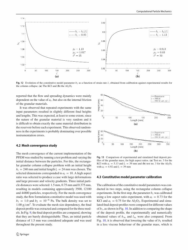
Fig. 12 Evolution of the constitutive model parameter b1 as a function of strain rate ε, obtained from calibration against experimental results forthe column collapse. (a) The KCl and (b) the Al2O3
reported that the flow and spreading dynamics were mainlydependent on the value of ai , but also on the internal frictionof the granular materials.
It was observed that repeated experiments with the sameinput parameters resulted in slightly different final heightsand lengths. This was expected, at least to some extent, sincethe nature of the granular material is very random and itis difficult to obtain exactly the same material distribution inthe reservoir before each experiment. This observed random-ness in the experiments is probably dominating over possibleinstrumentation errors.
4.2 Mesh convergence study
The mesh convergence of the current implementation of thePFEMwas studied by running a test problem and varying theinitial distance between the particles. For this, the rectangu-lar granular column collapse problem with an initial heighthi = 240 mm and initial length li = 24 mmwas chosen. Theselected dimensions corresponded to ai = 10. A high aspectratio was selected to produce a case with large deformationsand large pressure and velocity gradients. Three initial parti-cle distances were selected: 1.5mm, 0.75mm and 0.375mm,resulting in models containing approximately 3500, 12100and 44800 particles, respectively. For the mesh convergencestudy, the flow formulation constitutive model was used withb1 = 1.0 and b2 = 10−6 Pa. The bulk density was set to1.00 g/cm3. To evaluate the mesh size dependency, the finaldeposit profilewas extracted and compared for the threemod-els. In Fig. 9, the final deposit profiles are compared, showingthat they are barely distinguishable. Thus, an initial particledistance of 1.5 mm was considered adequate and was usedthroughout the present study.
Fig. 13 Comparison of experimental and simulated final deposit pro-files of the granular mass, for high aspect ratios. (a) Test no. 3 for theKCl with ai = 5.13 and li = 39 mm and (b) test no. 3 for the Al2O3with ai = 4.92 and li = 39 mm
4.3 Constitutive model parameter calibration
The calibration of the constitutivemodel parameterswas con-ducted in two steps, using the rectangular column collapseexperiments. In the first step, the parameter b1 was calibratedusing a low aspect ratio experiment, with ai = 0.73 for theKCl and ai = 0.75 for the Al2O3. Experimental and simu-lated final deposit profileswere compared for different valuesof b1, as shown in Fig. 10. In addition to comparing the shapeof the deposit profile, the experimentally and numericallyobtained values of h∞ and l∞ were also compared. FromFig. 10, it is observed that lowering the value of b1 resultedin a less viscous behaviour of the granular mass, which is
123
Computational Particle Mechanics
Table 2 Experimental and simulated final length l∞ and height h∞ from the series of column collapse experiments for KCl. Tests 1–3 were usedfor calibration and tests 4–17 for validation
Table 3 Experimental and simulated final length l∞ and height h∞ from the series of column collapse experiments for Al2O3. Tests 1–3 were usedfor calibration and tests 4–17 for validation
Fig. 14 Comparison ofexperimental and simulatednormalized final height h∞ as afunction of the initial aspectratio ai from the rectangularcolumn collapse. (a) The KCland (b) the Al2O3
reflected in a larger simulated value of l∞ for both mate-rials. Increasing the value of b1 resulted in a more viscousbehaviour and thus a smaller simulated value of l∞ for bothmaterials and an increased value of h∞ for the Al2O3, forthe range of investigated values of b1. Thus, b1 was adjustedto obtain a good fit to the experimental values of h∞ and l∞.The value of b1 that resulted in the most accurate predictionof the experimentally obtained h∞ and l∞ was obtained forthe KCl (b1 = 1.13) and for the Al2O3 (b1 = 0.83).
The flow formulation constitutive model was then usedwith the obtained values of b1 to simulate two additionalexperiments with increasingly larger aspect ratios. Experi-ments where ai = 2.15 and ai = 5.13 for the KCl andai = 2.15 and ai = 4.92 for the Al2O3 were considered.
Increasing the value of ai resulted in increasing strain ratesduring the column collapse, as shown in Fig. 11. The valueof b1 obtained through the initial calibration failed to pre-dict h∞ and l∞ for the experiments with larger ai , for boththe KCl and for the Al2O3. For the KCl, h∞ was overpre-dicted, while l∞ was underpredicted for increasing valuesof ai , indicating that a b1 = 1.13 overpredicted the mate-rial strength at increasing strain rates. For the Al2O3, it wasthe other way around, h∞ was underpredicted, while l∞ wasoverpredicted for increasing values of ai , indicating that ab1 = 0.83 underpredicted the material strength at increasingstrain rates.
Thus, to accuratelymodel the rectangular column collapseat increasing values of ai required a constitutive model able
123
Computational Particle Mechanics
Fig. 15 Comparison ofexperimental and simulatednormalized final length l∞ as afunction of the initial aspectratio ai from the rectangularcolumn collapse. (a) The KCland (b) the Al2O3
to account for the strain-rate-dependent material strength.The second constitutivemodel of the present study allows theinternal coefficient of friction (the parameter b1) of the mate-rial to be dependent on the strain rate. This model requiresthe definition of some additional parameters governing theevolution of the residual resistance μ, which is equal to b1for a granular material in which the effect of dilatancy canbe neglected. As presented in Sect. 3.2.2, these parametersare the lower and upper bounds of μ (μl and μu) and theequivalent deviatoric shear strain rate ε∗
s .In the literature [3,40,50], the identification of model
parameters corresponding to μl and μu has been discussed.The proposed relationships between the quasi-static materialstrength and the material strength at high strain rates varydepending on the granular material and the type of flow con-sidered. It is thus difficult to know this relationship a priori
for arbitrary granular materials and flow conditions. In thepresent study, the choice of relationship between μl and μu
was based on experimental observations from the columncollapses. For the KCl, the value of μl was set to be equal tothe previously obtained value of b1 = 1.13, while the valueof μu was set to 0.9 × b1. Thus, the residual resistance wasset to decrease with increasing strain rate. For the Al2O3,the value of μl was set equal to b1 = 0.83 and the valueof μu was set to 1.1 × b1. Thus, μ was set to increase withincreasing strain rate.
The remaining model parameter ε∗s governs the transition
between μl and μu with increasing strain rate shown con-ceptually in Fig. 5. The value of ε∗
s was obtained using threecolumn collapse experiments, where ai was varied between0.73 and 5.13 for the KCl and between 0.75 and 4.92 for theAl2O3. The same procedure that was used to calibrate b1 was
123
Computational Particle Mechanics
Fig. 16 Comparison of the in-plane velocity fields during the columncollapse for theAl2O3.MeasuredusingDIC (left column) and simulatedusing the PFEMwith the strain-rate-dependent residual strength consti-tutive model (right column). The horizontal component of the velocity
is compared in (a)–(b), and the vertical component is compared in (c)–(d). Results are from test no. 18 with ai = 0.60 and li = 80 mm. Theresults are compared at the normalized time t = 1.8
employed to calibrate ε∗s . The shape of the final deposit and
the values of h∞ and l∞ were compared for different valuesof ε∗
s . The best match to the experimentally obtained h∞ andl∞ was obtained with ε∗
s = 25 for the KCl and ε∗s = 10
for the Al2O3. In Fig. 13, the shape of the deposits obtainedexperimentally and with the two constitutive models of thepresent work is shown for the KCl and the Al2O3. The evo-lution of the parameter b1 as a function of the strain rate isshown in Fig. 12 for both granular materials.
The discrepancy between the experimental and the simu-lated deposit profiles in Fig. 13 is slight for the Al2O3, butmore prominent for the KCl. A possible explanation is thatthe assumption of using a continuum representation of a dis-crete media might be questionable in the case of KCl. Toaccurately model a discrete media as a continuum requiresthat the particles are much smaller than the smallest charac-teristic dimension of the process considered [21]. The sizeand the angular shape of the grains of the KCl, and the lengthscale of the experiments of the present study cause the flow-ing layer of grains to be thin in comparison with the grainsize in some of the experiments, thus making the continuumrepresentation questionable at that location. A further possi-ble explanation for the discrepancy is that the shape of the
grains of the KCl might result in some dilatation during thecolumn collapse, thus resulting in a slight volume increase.The dilatation is typically small for a granular material inthe fluid-like state [25], and it is typically neglected. In thepresent study, the granular materials are modelled as incom-pressible; thus, any dilatation is not taken into account whichis an additional contributing factor to the slight deviationbetween simulated and experimental profiles for the KCl.
It must also be noted that when using the PFEM, theremeshingmethodmay cause a slight variation of the volumeof the computational domain. To prevent this, the choice ofthe value of the alpha-shape parameter should be carefullyconsidered. The issue of volume conservation and remeshingin the PFEM is discussed in detail in [26] where it is sug-gested that values of the alpha-shape parameter close to 1.2keep the volume variation at acceptable levels for problemsof highly unsteady flows. Thus, throughout the present study,the value of the alpha-shape parameter was set to 1.2.
In the present study, a strategy for calibration of theconstitutive parameters based on a comparison betweenexperimental and simulated column collapses is presented.Using this approach, a set of constitutive parameters wereobtained for the two granular materials. To obtain a unique
123
Computational Particle Mechanics
Fig. 17 Comparison of the in-plane velocity fields during the columncollapse for the KCl. Measured using DIC (left column) and simulatedusing the PFEMwith the strain-rate-dependent residual strength consti-tutive model (right column). The horizontal component of the velocity
is compared in (a)–(b), and the vertical component of it is compared in(c)–(d). Results are from test no. 18 with ai = 0.83 and li = 72 mm.The results are compared at the normalized time t = 1.4
set of constitutive parameters is indeed a difficult task, partlybecause it is difficult to experimentally measure the evolu-tion of the frictional resistance as a function of the strainrate in a granular material. Thus, the parameters obtained inthis study are considered to be of use in the present appli-cation and at the investigated loading conditions. A strategyto obtain a unique set of constitutive parameters for arbitraryloading conditions and granularmaterialswould indeed be animprovement but lies outside the scope of the present study.
4.4 Model validation
To validate the proposed numerical model, a number of col-umn collapses with varying ai were simulated and comparedto experimental results. In total, the 17 cases from Table 1were simulated for each granular material, where ai was var-ied between 0.73 and 9.60 for the KCl and between 0.60 and9.70 for the Al2O3. Experimental and simulated values of l∞and h∞ are presented in Tables 2 and 3. The experimentally
measured h∞ and l∞ were normalized with respect to theinitial length li and were plotted as a function of ai , usinga logarithmic scale on both the horizontal and the verticalaxes, as shown in Figs. 14 and 15. The normalized h∞ andl∞ obtained from the simulations were plotted together withthe experimental results, as shown in Figs. 14 and 15. Whencomparing the experimental and numerical h∞ and l∞, itis observed that the strain-rate-dependent residual strengthconstitutive model is able to accurately predict the columncollapse at the investigated range of ai , for both the KCland the Al2O3. An error percentage for simulated l∞ andh∞ compared to experimental results was calculated and themedian of the error percentage was determined, excludingthe tests used for calibration of ε∗
s , as given in Tables 2 and3. For the KCl, comparing the median percentage errors, themost accurate prediction was obtained for the constitutivemodel without strain-rate-dependent residual strength. Forthe Al2O3, the strain-rate-dependent residual strength modelresulted in a more accurate prediction of l∞, while for h∞ a
123
Computational Particle Mechanics
similar accuracy was obtained for both constitutive models.The best model predictions resulted in median percentageerrors less than 5, for both granular materials.
To further compare the experimentally observed flowdynamics to the PFEM simulations, the horizontal and ver-tical velocity fields were extracted from the column collapseexperiment using DIC, as described in Sect. 2.2. In Figs. 16and 17, the horizontal and vertical velocity fields are com-pared for the Al2O3 with ai = 0.60 and li = 80 mm andfor the KCl with ai = 0.83 and li = 72 mm. Compared tothe experimentally measured velocities, the proposed strain-rate-dependent residual strength model was able to predictthe flow dynamics of the column collapse accurately. Fur-thermore, the time evolution of the column height during thecollapse was measured experimentally from the high-speedrecording of test no. 19, for both the KCl and the Al2O3.The test was simulated, and the time evolution is comparedin Fig. 18. The PFEM model resulted in a slight underpre-diction of the time it takes for the column to settle, with amore accurate prediction for the Al2O3 compared to that ofthe KCl. A possible reason for the underprediction is thatthe vertical removal of the door is not included in the sim-ulation. The finite time required to remove the door in theexperiments might affect the flow dynamics, causing a lowervertical velocity of the top layer of the column during the col-lapse, compared to a collapse where the door is not included.
In the present implementation of the PFEM, frictionbetween granular materials and surrounding structures is nottreated explicitly. This is due to the use of the incompressibil-ity condition to model the interaction between the deformingdomain and the fixed boundaries. Thus, the granular materialstrength governs the flow at the interface between granularmass and fixed boundaries. The use of a simplified contacttreatment is given some validity from an experimental studyby Lube et al. [51], where column collapses of a numberof different granular materials were conducted on three dif-ferent surfaces: a smooth wooden surface, a smooth plasticsurface and a rough surface made of sand paper. The authorsfound that the shape of the deposits was not significantlyaffected by the surface properties. It was suggested that apossible explanation for the independence of surface frictionwas the development of a dynamic interface a few particlesfrom the base surface, separating the flow between stationaryand moving granular material.
It should be noted that regardless of the choice of numeri-cal model for the transient granular material flow, validationhas to be performed to ensure reliable model predictions.The accurate DIC measurements of the granular materialflow dynamics provided a foundation to assess the validity ofthe proposed PFEM model. In this work, a two-dimensionalPFEM model was applied and validated for the fundamentalproblem of collapsing rectangular columns.
Fig. 18 Comparison of experimental and simulated time evolution ofcolumn height during the collapse. Results are from test no. 19, and thesimulations were performed using the strain-rate-dependent residualstrength constitutive model. (a) The Al2O3 with ai = 4.38 and li =21 mm and (b) the KCL with ai = 5.23 and li = 22 mm
5 Conclusions
The particle finite element method (PFEM) is used to modelthe transient granular material flow of a collapsing rect-angular column. A novel experimental methodology forquantification of the flow dynamics of the collapsing col-umn of granular material is designed. The experimentalresults are used to calibrate and validate the proposed numer-ical model. A conclusion from the present study is that theflow dynamics of the column collapse can be quantified bymeasuring the in-plane velocity field using digital image cor-relation. A numerical model, where the PFEM is used withtwo strain-rate-dependent constitutive models, is evaluatedand compared to experimental results. It is concluded thatthe PFEMmodel of the present study accurately predicts the
123
Computational Particle Mechanics
flow dynamics of the column collapse for two granular mate-rials with different material properties and over a range ofaspect ratios. By validation, it is shown that the strain-rate-dependent residual strength constitutive model is the mostaccurate for the Al2O3. In general, the best model predictionis obtained for the Al2O3, while some discrepancy betweenexperimental and simulated results is observed for the KCl.One possible cause of the discrepancy is that the length scaleof the granular material flow is too small for the KCl toaccurately model it as a continuum. The proposed novelstrain-rate-dependent residual strength constitutive modelrequires the calibration of only three parameters, the lowerand upper bounds of the residual resistance μl and μu and theequivalent deviatoric shear strain rate parameter ε∗
s . Thenum-ber of parameters of the proposed model is low compared toother numerical methods commonly used for the simulationof granular material flow, such as the DEM. In conclusion,the proposed PFEM model is a robust numerical tool that isuseful for modelling transient granular material flow.
Acknowledgements Open access funding provided by Lulea Univer-sity of Technology. For the financial support of theHorizon 2020Project“Development of smart and flexible freight wagons and facilities forimproved transport of granular multimaterials”, Project Id: 636520, theEuropean Commission is gratefully acknowledged. For financial sup-port of the Project “HARSHWORK”, Project Agreement No. 17152,KIC RawMaterials is gratefully acknowledged.
Funding This study was partly funded by the European Commission(Project Id: 636520) and by KIC Raw Materials (Project AgreementNo. 17152).
Compliance with ethical standards
Conflict of interest The authors declare that they have no conflict ofinterest.
Open Access This article is licensed under a Creative CommonsAttribution 4.0 International License, which permits use, sharing, adap-tation, distribution and reproduction in any medium or format, aslong as you give appropriate credit to the original author(s) and thesource, provide a link to the Creative Commons licence, and indi-cate if changes were made. The images or other third party materialin this article are included in the article’s Creative Commons licence,unless indicated otherwise in a credit line to the material. If materialis not included in the article’s Creative Commons licence and yourintended use is not permitted by statutory regulation or exceeds thepermitted use, youwill need to obtain permission directly from the copy-right holder. To view a copy of this licence, visit http://creativecommons.org/licenses/by/4.0/.
References
1. Andersen S, Andersen L (2010) Modelling of landslides with thematerial-point method. Comput Geosci 14(1):137–147
2. Andrade JE, Ellison KC (2008) Evaluation of a predictive consti-tutive model for sands. J Geotech Geoenviron Eng 134(12):1825–1828
3. Andrade JE, Chen Q, Le PH, Avila CF, Matthew Evans T (2012)On the rheology of dilative granular media: bridging solid- andfluid-like behavior. J Mech Phys Solids 60(6):1122–1136
4. BalmforthNJ,KerswellRR (2005)Granular collapse in twodimen-sions. J Fluid Mech 538:399–428
5. BuiHH, FukagawaR, SakoK,OhnoS (2008)Lagrangianmeshfreeparticles method (SPH) for large deformation and failure flowsof geomaterial using elastic-plastic soil constitutive model. Int JNumer Anal Methods Geomech 32(12):1537–1570
7. Cabiscol R, Finke JH, Kwade A (2018) Calibration and interpreta-tion of DEM parameters for simulations of cylindrical tablets withmulti-sphere approach. Powder Technol 327:232–245
8. Cante JC, Riera MD, Oliver J, Prado JM, Isturiz A, Gonzalez C(2011) Flow regime analyses during the filling stage in powdermet-allurgy processes: experimental study and numerical modelling.Granul Matter 13(1):79–92
9. Cante JC, Dávalos C, Hernández JA, Oliver J, Jonsén P, Gustafs-son G, Häggblad H (2014) PFEM-based modeling of industrialgranular flows. Comput Part Mech 1(1):47–70
10. Chen Z, HuW, Shen L, Xin X, Brannon R (2002) An evaluation ofthe MPM for simulating dynamic failure with damage diffusion.Eng Fract Mech 69(17):1873–1890
11. Cremonesi M, Frangi A, Perego U (2011) A Lagrangian finiteelement approach for the simulation of water-waves induced bylandslides. Comput Struct 89(11–12):1086–1093
12. Cremonesi M, Ferri F, Perego U (2017) A basal slip model forLagrangianfinite element simulations of 3D landslides. Int JNumerAnal Methods Geomech 41(1):30–53
13. Crosta GB, Imposimato S, Roddeman D (2009) Numerical mod-eling of 2-D granular step collapse on erodible and nonerodiblesurface. J Geophys Res Solid Earth 114(3):1–19
14. Crosta GB, Imposimato S, Roddeman D (2015) Granular flows onerodible and non erodible inclines. Granul Matter 17(5):667–685
15. Cundall PA, Strack ODL (1979) A discrete numerical model forgranular assemblies. Géotechnique 29(1):47–65
16. Dávalos C, Cante J, Hernández JA, Oliver J (2015) On the numer-ical modeling of granular material flows via the particle finiteelement method (PFEM). Int J Solids Struct 71:99–125
17. Desai CS, Siriwardane HJ (1984) Constitutive laws for engineer-ing materials, with emphasis on geologic materials. Prentice-Hall,Englewood Cliffs
18. Dohrmann CR, Bochev PB (2004) A stabilized finite elementmethod for the Stokes problem based on polynomial pressure pro-jections. Int J Numer Methods Fluids 46(2):183–201
19. Drucker D, Prager W (1952) Soil mechanics and plastic analysisor limit design. Q Appl Math 9(2):157–165
20. Dunatunga S, Kamrin K (2015) Continuum modelling and simu-lation of granular flows through their many phases. J Fluid Mech779:483–513
21. Duran J (2000) Sands, powders, and grains : an introduction to thephysics of granular materials. Springer, New York
22. Edelsbrunner H, Mücke EP (1994) Three-dimensional alphashapes. ACM Trans Graph 13(1):43–72
23. Elaskar SA, Godoy LA, Gray DD, Stiles JM (2000) A viscoplasticapproach to model the flow of granular solids. Int J Solids Struct37(15):2185–2214
24. Fern EJ, Soga K (2016) The role of constitutive models inMPM simulations of granular column collapses. Acta Geotech11(3):659–678
25. Forterre Y, Pouliquen O (2008) Flows of dense granular media.Annu Rev Fluid Mech 40(1):1–24
26. Franci A, Cremonesi M (2017) On the effect of standard PFEMremeshing on volume conservation in free-surface fluid flow prob-lems. Comput Part Mech 4(3):331–343
27. Gan JQ, Zhou ZY, Yu AB (2016) A GPU-based DEM approach formodelling of particulate systems. Powder Technol 301:1172–1182
28. Gingold RA, Monaghan JJ (1977) Smoothed particle hydrody-namics: theory and application to non-spherical stars. Mon NotR Astron Soc 181(3):375–389
29. GOM GmbH (2007) ARAMIS User Manual - Software v6.1.Braunschweig
30. Hurley RC, Andrade JE (2017) Continuum modeling of rate-dependent granular flows in SPH.Comput PartMech 4(1):119–130
31. Iaconeta I, Larese A, Rossi R, Guo Z (2017) Comparison of amate-rial pointmethod and a galerkinmeshfreemethod for the simulationof cohesive-frictional materials. Materials 10(10):1150
32. Iaconeta I, Larese A, Rossi R, Oñate E (2019) A stabilized mixedimplicit material point method for non-linear incompressible solidmechanics. Comput Mech 63(6):1243–1260
33. Idelsohn SR, Oñate E, Del Pin F (2003) A Lagrangian meshlessfinite element method applied to fluid-structure interaction prob-lems. Comput Struct 81(8–11):655–671
34. Idelsohn SR, Oñate E, Del Pin F (2004) The particle finite elementmethod: a powerful tool to solve incompressible flows with free-surfaces and breaking waves. Int J Numer Methods Eng 61:964–989
35. Jaeger HM, Nagel SR, Behringer RP (1996) Granular solids, liq-uids, and gases. Rev Mod Phys 68(4):1259–1273
37. Jonsén P, Pålsson B, Häggblad H (2012) A novel method for full-body modelling of grinding charges in tumbling mills. Miner Eng33:2–12
38. Jonsén P, Pålsson B, Stener J, Häggblad H (2014) A novel methodfor modelling of interactions between pulp, charge and mill struc-ture in tumbling mills. Miner Eng 63:65–72
39. Jonsén P, Stener JF, Pålsson BI, Häggblad H (2015) Validation ofa model for physical interactions between pulp, charge and millstructure in tumbling mills. Miner Eng 73:77–84
40. Jop P, Forterre Y, Pouliquen O (2006) A constitutive law for densegranular flows. Nature 441:727–730
41. Kajberg J, Lindkvist G (2004) Characterisation of materials sub-jected to large strains by inverse modelling based on in-planedisplacement fields. Int J Solids Struct 41(13):3439–3459
42. Karlsson T, Klisinski M, Runesson K (1998) Finite element sim-ulation of granular material flow in plane silos with complicatedgeometry. Powder Technol 99(1):29–39
43. Lajeunesse E,Mangeney-CastelnauA,Vilotte JP (2004) Spreadingof a granular mass on a horizontal plane. Phys Fluids 16(7):2371–2381
44. Lajeunesse E, Monnier JB, Homsy GM (2005) Granular slumpingon a horizontal surface. Phys Fluids 17(10):1–15
45. LareseA (2017)ALagrangian PFEMapproach for non-Newtonianviscoplastic materials. Rev Int Metodos Numer Calc Disen Ing33(3–4):307–317
46. Larese A, Rossi R, Oñate E, ToledoM,Morán R, CamposH (2015)Numerical and experimental study of overtopping and failure ofrockfill dams. Int J Geomech 15(4):1–23
47. Larsson S,GustafssonG,OudichA, Jonsén P,HäggbladHH (2016)Experimental methodology for study of granular material flowusing digital speckle photography. Chem Eng Sci 155:524–536
48. LarssonS,GustafssonG,HäggbladH, JonsénP (2017)Experimen-tal and numerical study of potassium chloride flow using smoothedparticle hydrodynamics. Miner Eng 116:88–100
49. Lee DT, Schachter BJ (1980) Two algorithms for constructing aDelaunay triangulation. Int J Comput Inf Sci 9(3):219–242
50. Liang Df, He Xz (2014) A comparison of conventional and shear-rate dependent Mohr–Coulomb models for simulating landslides.J Mt Sci 11(6):1478–1490
51. Lube G, Huppert HE, Sparks RSJ, Hallworth MA (2004) Axisym-metric collapses of granular columns. J Fluid Mech 508:175–199
52. Lube G, Huppert HE, Stephen R, Sparks J, Freundt A (2005)Collapses of two-dimensional granular columns. Phys Rev E72:041301
53. Lucy LB (1977) A numerical approach to the testing of the fissionhypothesis. Astron J 82(12):1013–1024
54. Manzari MT, Dafalias YF (1997) A critical state two-surface plas-ticity model for sands. Géotechnique 47(2):255–272
55. Mast CM, Arduino P, Mackenzie-Helnwein P, Miller GR (2014)Simulating granular column collapse using the material pointmethod. Acta Geotech 10(1):101–116
56. Midi G (2004) On dense granular flows. Eur Phys J E 14(4):341–365
57. NguyenCT,NguyenCT, BuiHH,NguyenGD, FukagawaR (2017)A new SPH-based approach to simulation of granular flows usingviscous damping and stress regularisation. Landslides 14(1):69–81
58. Nonoyama H, Moriguchi S, Sawada K, Yashima A (2015) Slopestability analysis using smoothed particle hydrodynamics ( SPH )method. Soils Found 55(2):458–470
59. Oliver J, Cante JC, Weyler R, González C, Hernandez J (2007)Particle finite element methods in solid mechanics problems. In:Oñate E, Owen R (eds) Computational plasticity. Computationalmethods in applied sciences, vol 7. Springer,Dordrecht, pp 87–103.https://doi.org/10.1007/978-1-4020-6577-4_6
60. Oñate E, Idelsohn SR, Del Pin F, Aubry R (2004) The particle finiteelementmethod—an overview. Int J ComputMethods 01(02):267–307
61. Oñate E, Idelsohn SR, Celigueta MA, Rossi R, Marti J, Car-bonell JM, Ryzhakov P, Suárez B (2011) Advances in the particlefinite element method (PFEM) for solving coupled problems inengineering. In: Oñate E, Owen R (eds) Particle-based methods,computational methods in applied sciences. Springer, Berlin
62. Pan B, Qian K, Xie H, Asundi A (2009) Two-dimensional digitalimage correlation for in-plane displacement and strain measure-ment: a review. Meas Sci Technol 20(6):062001
63. Peng C, Guo X, WuW,Wang Y (2016) Unified modelling of gran-ular media with smoothed particle hydrodynamics. Acta Geotech11(6):1231–1247
64. Pestana JM,WhittleAJ (1999) Formulation of a unified constitutivemodel for clays and sands. Int J Numer Anal Methods Geomech23(12):1215–1243
65. Pouliquen O, Cassar C, Jop P, Forterre Y, Nicolas M (2006) Flowof dense granular material: towards simple constitutive laws. J StatMech Theory Exp 2006(07):P07020
66. Radjai F, Richefeu V (2009) Contact dynamics as a nonsmoothdiscrete element method. Mech Mater 41(6):715–728
67. Rodríguez JM, Jonsén P, Svoboda A (2017) Simulation of metalcutting using the particle finite-element method and a physicallybased plasticity model. Comput Part Mech 4(1):35–51
68. Rodríguez JM, Carbonell JM, Jonsén P (2018) NumericalMethodsfor the modelling of chip formation. Arch Comput Methods Eng.https://doi.org/10.1007/s11831-018-09313-9
69. Saabye Ottosen N, Ristinmaa M (2005) The mechanics of consti-tutive modeling, 1st edn. Elsevier, Amsterdam
70. Salazar F, Irazábal J, Larese A, Oñate E (2016) Numerical mod-elling of landslide-generated waves with the particle finite elementmethod (PFEM) and a non-Newtonian flow model. Int J NumerAnal Methods Geomech 40(6):809–826
71. Samiei K, Peters B, Bolten M, Frommer A (2013) Assessment ofthe potentials of implicit integration method in discrete elementmodelling of granular matter. Comput Chem Eng 49:183–193
72. Servin M, Wang D, Lacoursière C, Bodin K (2014) Examining thesmooth and nonsmooth discrete element approaches to granularmatter. Int J Numer Methods Eng 97(12):878–902
73. Sielamowicz I, Blonski S, Kowalewski TAA (2005) Optical tech-nique DPIV in measurements of granular material flows, part 1 of3—plane hoppers. Chem Eng Sci 60(2):589–598
74. Sołowski WT, Sloan SW (2015) Evaluation of material pointmethod for use in geotechnics. Int JNumerAnalMethodsGeomech39(7):685–701
75. SulskyD,ChenZ, SchreyerH (1994)Aparticlemethod for history-dependent materials. Comput Methods Appl Mech Eng 118(1–2):179–196
76. Sulsky D, Zhou SJ, Schreyer HL (1995) Application of a particle-in-cell method to solid mechanics. Comput Phys Commun 87(1–2):236–252
77. US Geological Survey (2010) Metals and minerals: U.S. Geologi-cal SurveyMineralsYearbook2008, v. 1.U.S.GovernmentPrintingOffice, Reston, Virginia, United States
78. Wang Y, Lu Y, Ooi JY (2013) Numerical modelling of dynamicpressure and flow in hopper discharge using the arbitraryLagrangian–Eulerian formulation. Eng Struct 56:1308–1320
79. Warnett JM, Denissenko P, Thomas PJ, Kiraci E, Williams MA(2014) Scalings of axisymmetric granular column collapse. GranulMatter 16(1):115–124
80. Wieckowski Z, Kowalska-Kubsik I (2011) Non-local approach inmodelling of granular flow by the material point method. In: Pro-ceedings of computer methods in mechanics, Warsaw, Poland, pp101–102
81. Willert CE, Gharib M (1991) Digital particle image velocimetry.Exp Fluids 10(4):181–193
82. Wu CY, Cocks ACF (2006) Numerical and experimental investi-gations of the flow of powder into a confined space. Mech Mater38(4):304–324
83. WuYH, Hill JM, YuA (2007) A finite element method for granularflow through a frictional boundary. Commun Nonlinear Sci NumerSimul 12(4):486–495
84. Xu X, Harada K (2003) Automatic surface reconstruction withalpha-shape method. Vis Comput 19(7–8):431–443
85. Xu X, Sun Q, Jin F, Chen Y (2016) Measurements of velocity andpressure of a collapsing granular pile. Powder Technol 303:147–155
86. Zhang X, Krabbenhoft K, Sheng D, Li W (2015) Numerical sim-ulation of a flow-like landslide using the particle finite elementmethod. Comput Mech 55(1):167–177
87. Zienkiewicz OC, Godbole PN (1974) Flow of plastic and visco-plastic solids with special reference to extrusion and formingprocesses. Int J Numer Methods Eng 8(1):1–16
88. ZienkiewiczOC, Taylor RL, Zhu JZ (2013) Finite elementmethod:its basis and fundamentals, 7th edn. Butterworth-Heinemann, Lon-don
Publisher’s Note Springer Nature remains neutral with regard to juris-dictional claims in published maps and institutional affiliations.