Submit comments about this document by clicking the Feedback [+] link at: http://docs.sun.com StorageTek SL500 Modular Library System User’s Guide Part Number: 96116 June 2010, Revision: KB
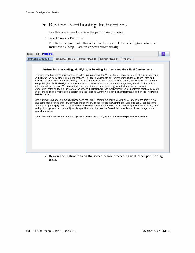
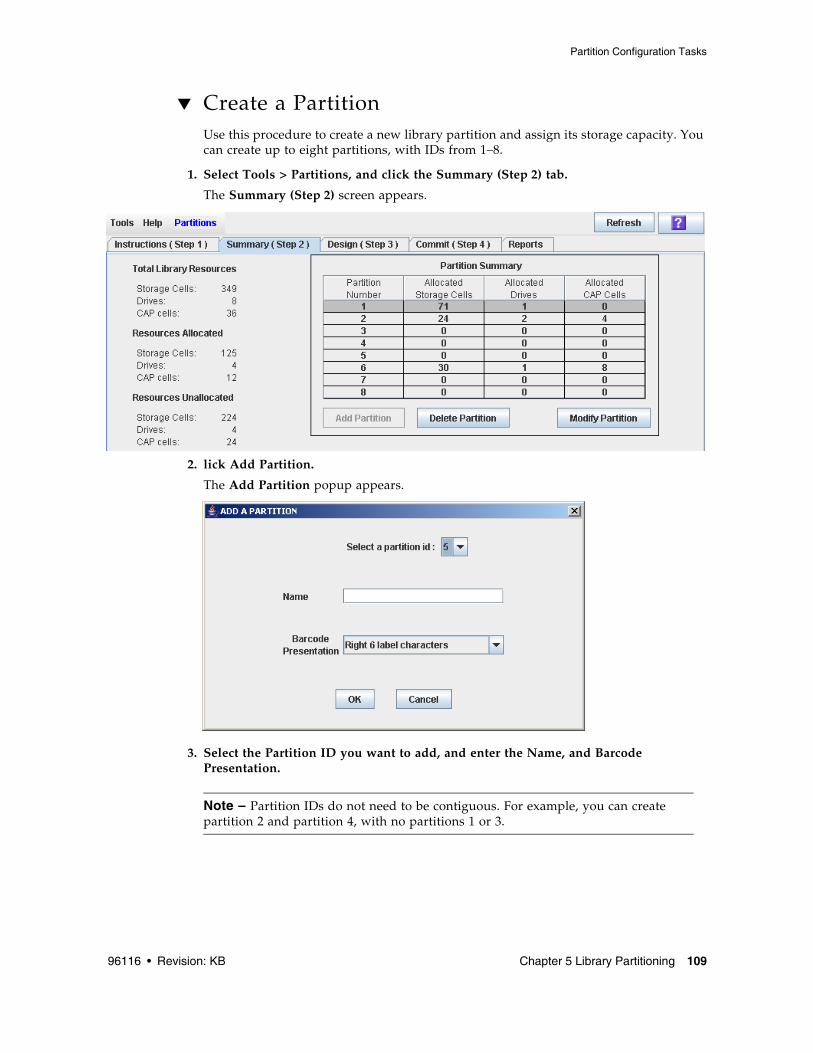
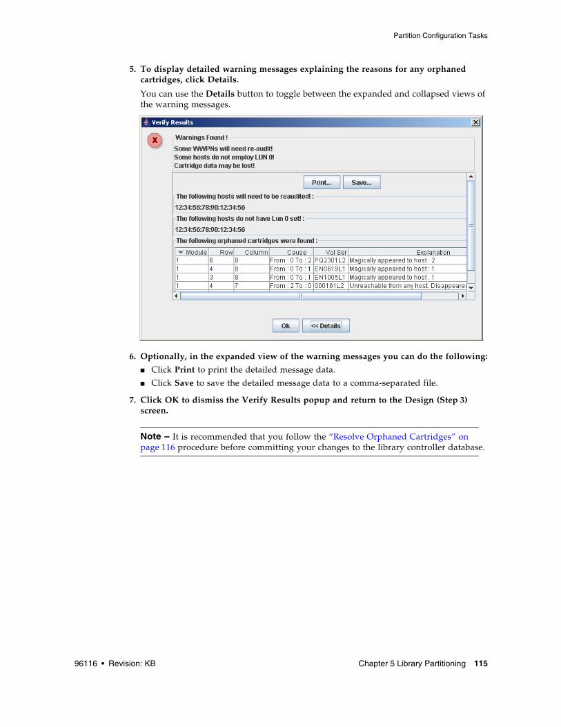
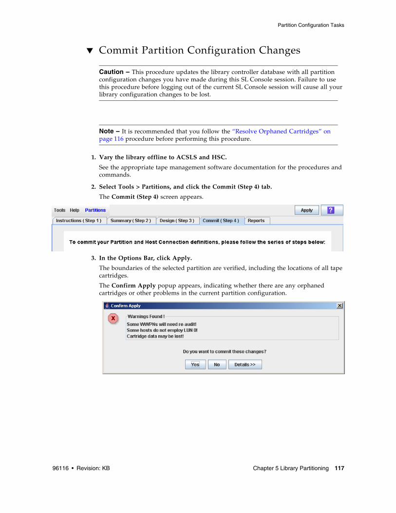
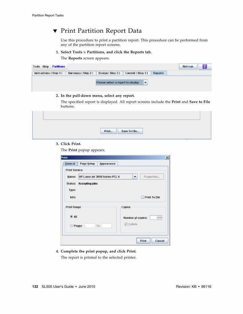
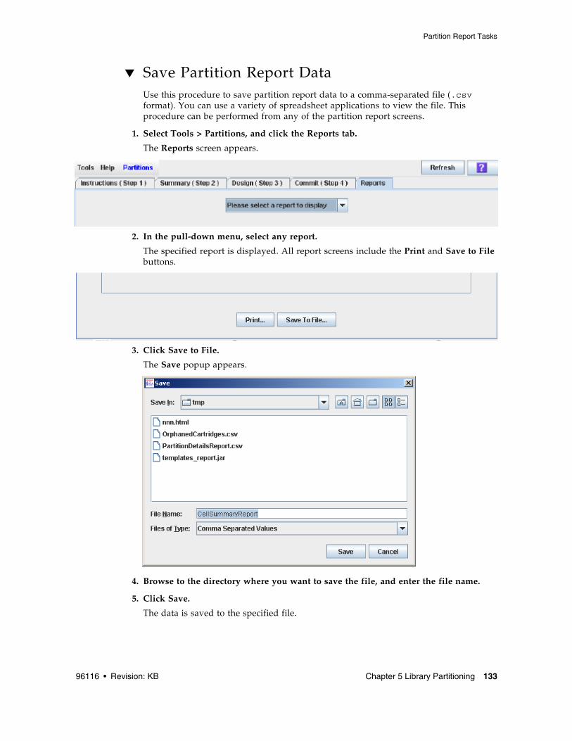
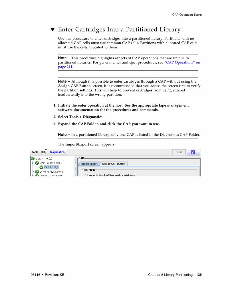
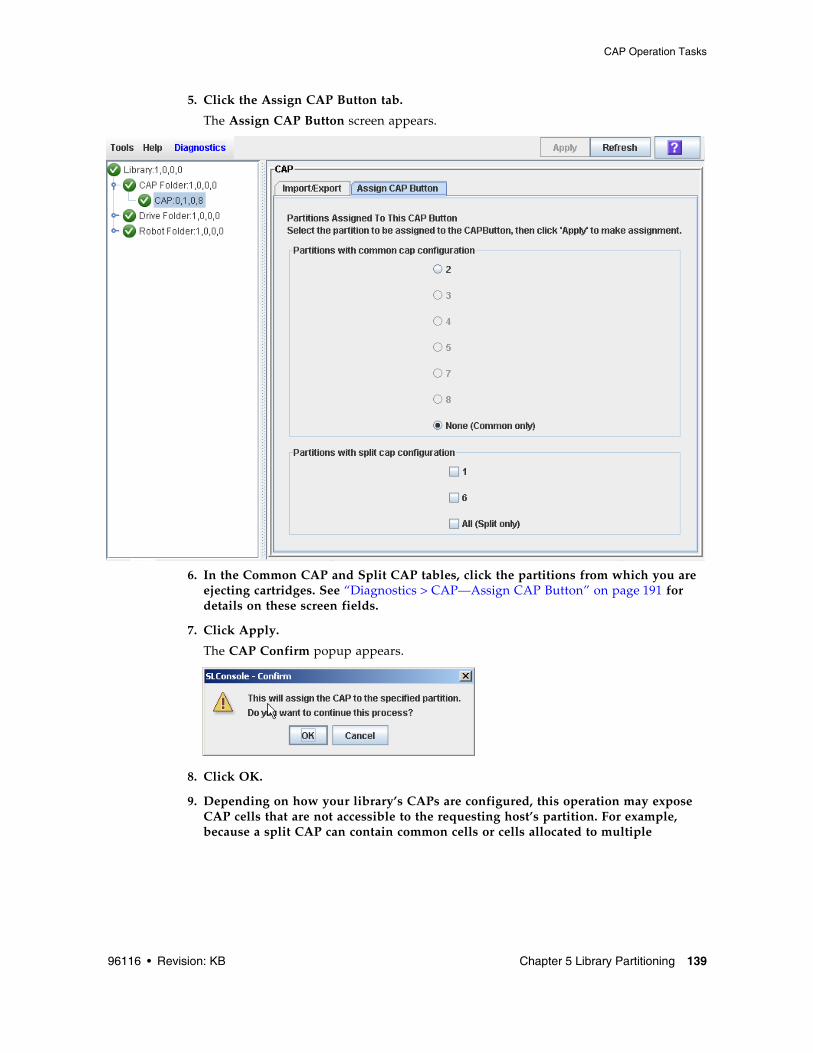
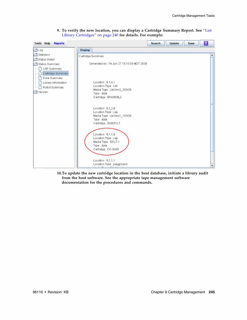
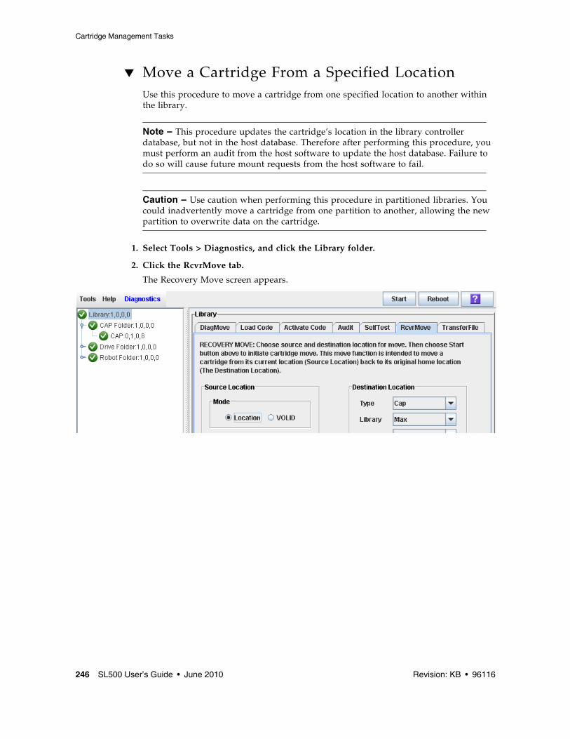
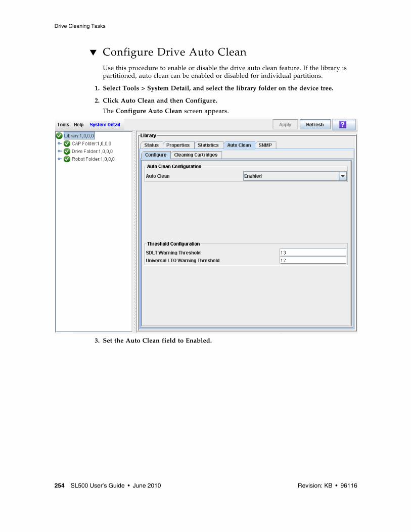
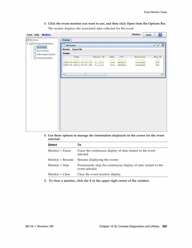
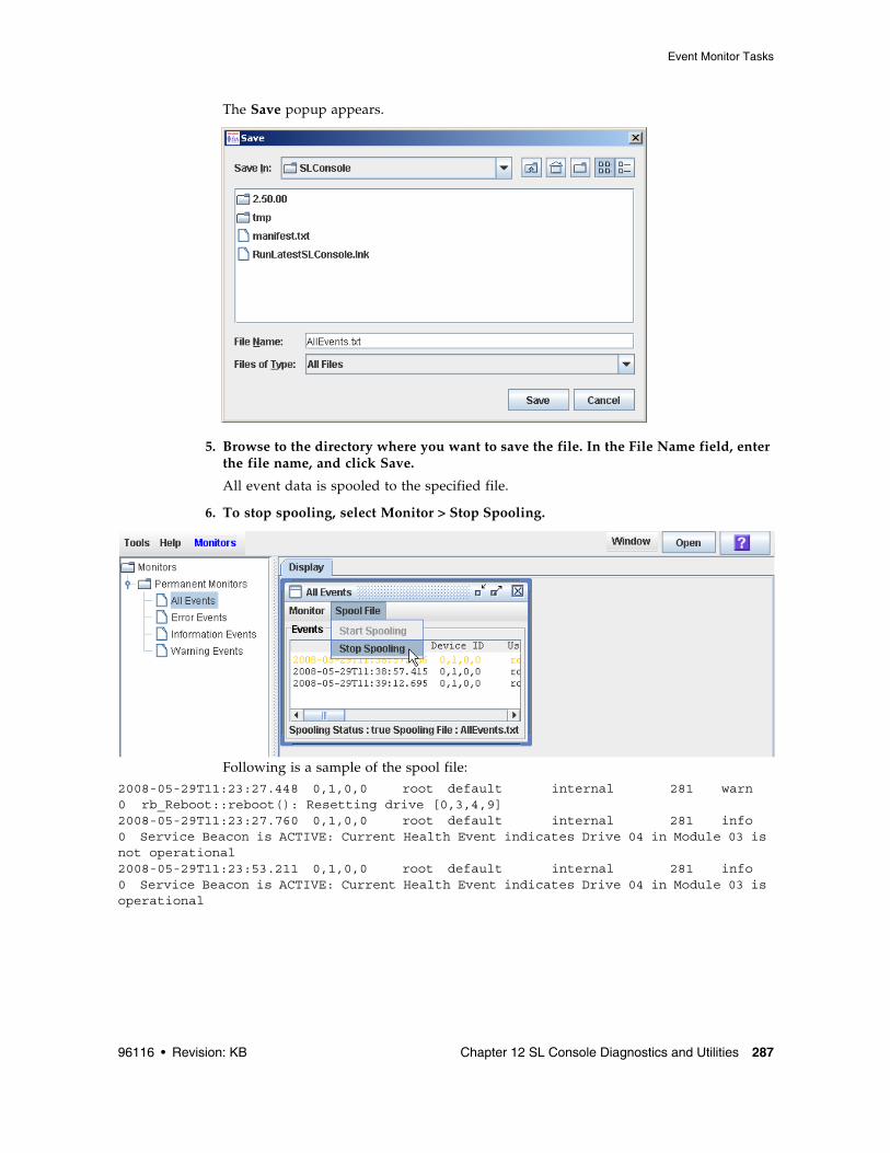
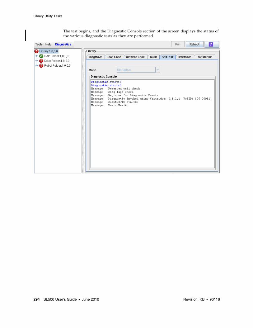
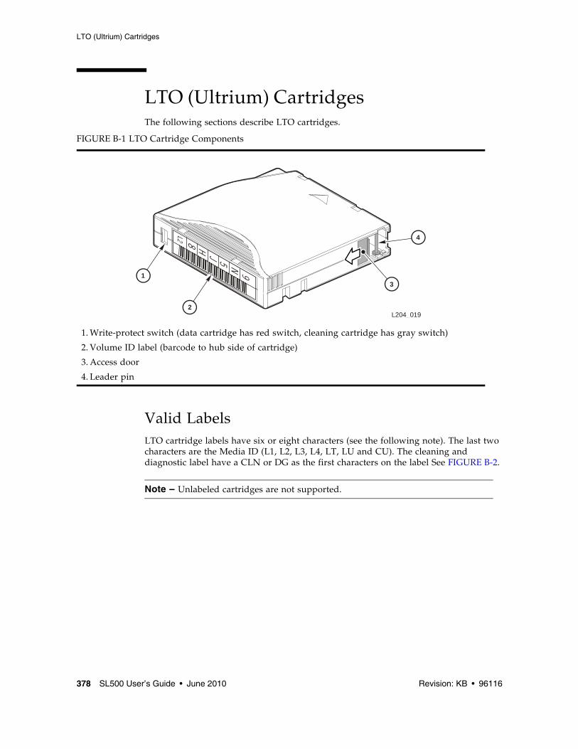
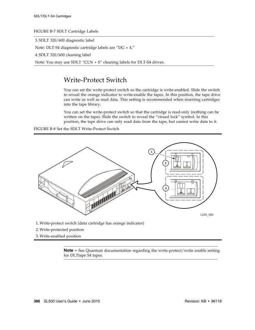
Transcript
Submit comments about this document by clicking the Feedback [+] link at: http://docs.sun.com
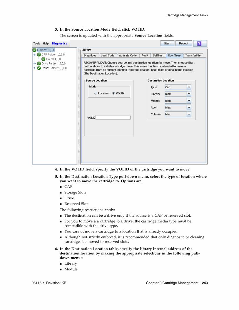
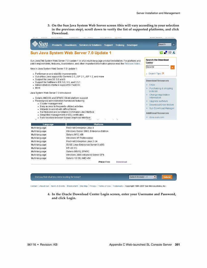
StorageTek SL500Modular Library System
User’s Guide
Part Number: 96116 June 2010, Revision: KB
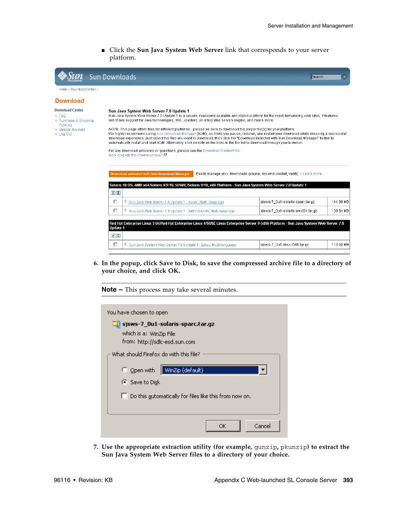
ii SL500 User’s Guide • June 2010 Revision: KB • 96116
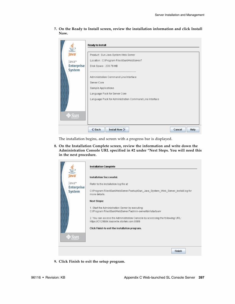
This software and related documentation are provided under a license agreement containing restrictions on use and disclosure and are protected by intellectual property laws. Except as expressly permitted in your license agreement or allowed by law, you may not use, copy, reproduce, translate, broadcast, modify, license, transmit, distribute, exhibit, perform, publish, or display any part, in any form, or by any means. Reverse engineering, disassembly, or decompilation of this software, unless required by law for interoperability, is prohibited.
The information contained herein is subject to change without notice and is not warranted to be error-free. If you find any errors, please report them to us in writing.
If this is software or related software documentation that is delivered to the U.S. Government or anyone licensing it on behalf of the U.S. Government, the following notice is applicable:
U.S. GOVERNMENT RIGHTS Programs, software, databases, and related documentation and technical data delivered to U.S. Government customers are "commercial computer software" or "commercial technical data" pursuant to the applicable Federal Acquisition Regulation and agency-specific supplemental regulations. As such, the use, duplication, disclosure, modification, and adaptation shall be subject to the restrictions and license terms set forth in the applicable Government contract, and, to the extent applicable by the terms of the Government contract, the additional rights set forth in FAR 52.227-19, Commercial Computer Software License (December 2007). Oracle USA, Inc., 500 Oracle Parkway, Redwood City, CA 94065.
This software or hardware is developed for general use in a variety of information management applications. It is not developed or intended for use in any inherently dangerous applications, including applications which may create a risk of personal injury. If you use this software or hardware in dangerous applications, then you shall be responsible to take all appropriate fail-safe, backup, redundancy, and other measures to ensure the safe use. Oracle Corporation and its affiliates disclaim any liability for any damages caused by use of this software or hardware in dangerous applications.
Oracle is a registered trademark of Oracle Corporation and/or its affiliates. Oracle and Java are registered trademarks of Oracle and/or its affiliates. Other names may be trademarks of their respective owners.
AMD, Opteron, the AMD logo, and the AMD Opteron logo are trademarks or registered trademarks of Advanced Micro Devices. Intel and Intel Xeon are trademarks or registered trademarks of Intel Corporation. All SPARC trademarks are used under license and are trademarks or registered trademarks of SPARC International, Inc. UNIX is a registered trademark licensed through X/Open Company, Ltd.
This software or hardware and documentation may provide access to or information on content, products, and services from third parties. Oracle Corporation and its affiliates are not responsible for and expressly disclaim all warranties of any kind with respect to third-party content, products, and services. Oracle Corporation and its affiliates will not be responsible for any loss, costs, or damages incurred due to your access to or use of third-party content, products, or services.
96116 • Revision: KB iii
Contents
Summary of Changes xix
Preface xxiii
Related Documentation xxiii
Documentation, Support, and Training xxv
Oracle Welcomes Your Comments xxv
1. SL500 Introduction 1
Views and Locations 2
Library with LTO Storage Cells 4
LTO Library Configurations 4
LTO Library Internal Addressing 4
LTO Storage Cell and Drive Capacities 5
Adding LTO Storage Cell Capacity 6
Library with Mixed-Media Storage Cells 7
Mixed-Media Library Configurations 7
Mixed-Media Library Internal Addressing 7
Mixed-Media Storage Cell and Drive Capacities 8
Adding Mixed-Media Storage Cell Capacity 9
Controls and Indicators 10
Power Switch 10
Power Supply LED 10
Drive Tray LED 10
Keypad 10
RLC Card Indicators 14
iv SL500 User’s Guide • June 2010 Revision: KB • 96116
Tape Drives and Cartridges 15
LTO Tape Drives and Cartridges 16
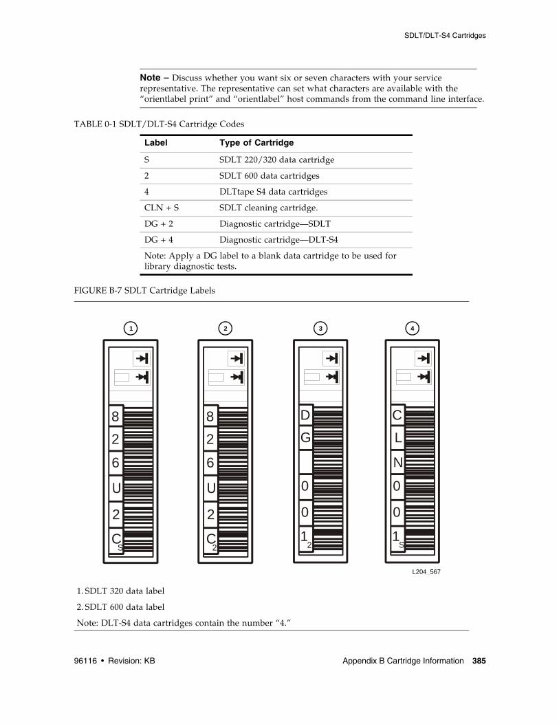
SDLT/DLT-S4 Tape Drives and Cartridges 16
Cartridge Access Ports 18
Robotics Unit 18
Power System 21
Cooling 21
Electronics 22
RLC Card 22
Interface Cards 22
Safety Features 23
Cards and Power Supply 23
Robotics 23
Front Door 23
Interfaces 24
Tape Management Software 25
2. StorageTek Library Console 27
Introduction 27
SL Console Modes 27
SL Console Security 28
User IDs 28
Activation Password 28
SL Console Screen Display 29
Modifying the Screen Layout 30
Synchronizing the Display With the Controller Database 30
Logging In 30
Making Library Configuration Updates 30
SL Console Reports 32
Report Types 32
Report Options Bar 32
Report Procedures 33
SL Console Help 34
Accessing the SL Console Help 34
96116 • Revision: KB Contents v
Help Navigation 34
Tips for Using the SL Console Help 35
Web-launched SL Console 36
Security Considerations 36
Client Requirements 36
Web-launched SL Console Updates 36
Starting the Web-launched SL Console on a Client 37
Standalone SL Console 38
Security Considerations 38
Installation Requirements 38
Standalone SL Console Updates 39
SL Console Task Summary 40
General SL Console Usage Tasks 41
Log in to the Web-launched SL Console Using a Browser or Command Line 42
Log in to the Web-launched SL Console Using an Icon 47
Log in to the Standalone SL Console 51
Log Off the SL Console 53
Change a User Password 54
General SL Console Report Tasks 55
Display a Library Report 56
Search a Library Report 58
Save Library Report Data to a File 60
Standalone SL Console Installation Tasks 62
Download the Standalone SL Console Installer 63
Install the Standalone SL Console 64
3. Hardware Activation Files 69
Hardware Activation File 69
Hardware Activation File Tasks 70
Hardware Activation File Installation Process 70
Hardware Activation File Task Summary 71
Receive a New Hardware Activation File 72
Install a New Hardware Activation File on the Target Library 73
Display Current Hardware Activation Files 75
vi SL500 User’s Guide • June 2010 Revision: KB • 96116
Delete a Hardware Activation File 76
Hardware Activation Screen Reference 79
Hardware Activation > Current Hardware Activation Keys 80
Nomenclature changes for “hardware activation files”. Changes throughout, but majority of changes in the following chapters:■ Chapter 3, “Hardware Activation Files” –
Chapter title changed from “Licensing”. Changes to all screens and tasks.
■ Chapter 4, “Capacity on Demand”■ Chapter 5, “Partitioning”
EC000591 July 2008 KA
Updated the following chapters for new License Management and Capacity on Demand features. ■ Chapter 3, “Licensing” (new chapter)■ Chapter 4, “Capacity on Demand” (new chapter)■ Chapter 5, “Library Partitioning”
xx SL500 User’s Guide • June 2010 Revision: KB • 96116
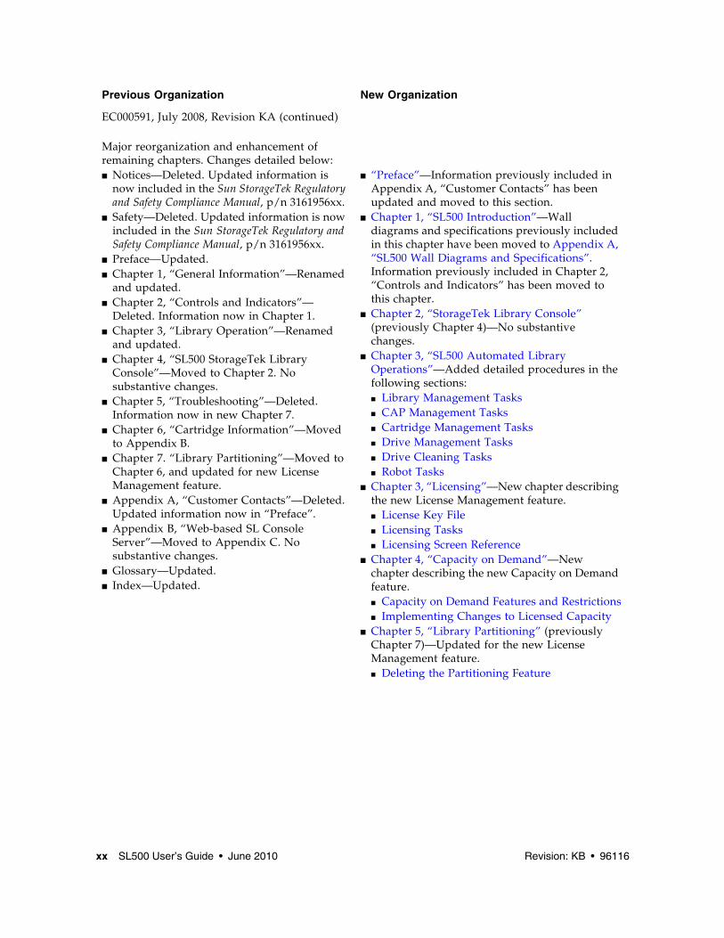
Previous Organization New Organization
EC000591, July 2008, Revision KA (continued)
Major reorganization and enhancement of remaining chapters. Changes detailed below:■ Notices—Deleted. Updated information is
now included in the Sun StorageTek Regulatory and Safety Compliance Manual, p/n 3161956xx.
■ Safety—Deleted. Updated information is now included in the Sun StorageTek Regulatory and Safety Compliance Manual, p/n 3161956xx.
and updated. ■ Chapter 2, “Controls and Indicators”—
Deleted. Information now in Chapter 1. ■ Chapter 3, “Library Operation”—Renamed
and updated. ■ Chapter 4, “SL500 StorageTek Library
Console”—Moved to Chapter 2. No substantive changes.
■ Chapter 5, “Troubleshooting”—Deleted. Information now in new Chapter 7.
■ Chapter 6, “Cartridge Information”—Moved to Appendix B.
■ Chapter 7. “Library Partitioning”—Moved to Chapter 6, and updated for new License Management feature.
■ Appendix A, “Customer Contacts”—Deleted. Updated information now in “Preface”.
■ Appendix B, “Web-based SL Console Server”—Moved to Appendix C. No substantive changes.
■ Glossary—Updated. ■ Index—Updated.
■ “Preface”—Information previously included in Appendix A, “Customer Contacts” has been updated and moved to this section.
■ Chapter 1, “SL500 Introduction”—Wall diagrams and specifications previously included in this chapter have been moved to Appendix A, “SL500 Wall Diagrams and Specifications”. Information previously included in Chapter 2, “Controls and Indicators” has been moved to this chapter.
■ Chapter 3, “SL500 Automated Library Operations”—Added detailed procedures in the following sections:■ Library Management Tasks■ CAP Management Tasks■ Cartridge Management Tasks■ Drive Management Tasks■ Drive Cleaning Tasks■ Robot Tasks
■ Chapter 3, “Licensing”—New chapter describing the new License Management feature.■ License Key File■ Licensing Tasks■ Licensing Screen Reference
■ Chapter 4, “Capacity on Demand”—New chapter describing the new Capacity on Demand feature.■ Capacity on Demand Features and Restrictions■ Implementing Changes to Licensed Capacity
■ Chapter 5, “Library Partitioning” (previously Chapter 7)—Updated for the new License Management feature.■ Deleting the Partitioning Feature
96116 • Revision: KB Summary of Changes xxi
EC000591, July 2008, Revision KA (continued) ■ Chapter 12, “SL Console Diagnostics and Utilities”—New chapter describing the following:■ Library Events■ Library Self-Tests■ Library Firmware Upgrades■ Audits■ Robot Diagnostic Moves■ Troubleshooting—Information included in
■ Chapter 13, “SNMP Support”—New chapter describing the following:■ Trap Levels■ Port Control■ Access Control■ SNMP Configuration and Usage Tasks
■ Chapter 14, “Manual Operations”—New chapter describing the following:■ Library Safety■ General Library Operation Tasks■ Cartridge Handling Tasks
■ Appendix A, “SL500 Wall Diagrams and Specifications”—Wall diagrams and library specifications previously included in Chapter 1, “General Information” have been moved to this appendix.
■ Appendix B, “Cartridge Information”—Moved from previous Chapter 6.
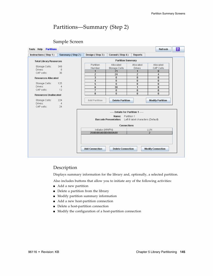
descriptions of the concepts, tasks, and SL Console screens involved in library partitioning.
Added information regarding the Web-launched SL Console feature:■ Chapter 2, “StorageTek Library
Console”—Detailed instructions for installing and using the Web-launched SL Console client.
■ Appendix C, “Web-launched SL Console Server”—Detailed instructions for installing and managing the Web-launched SL Console server.
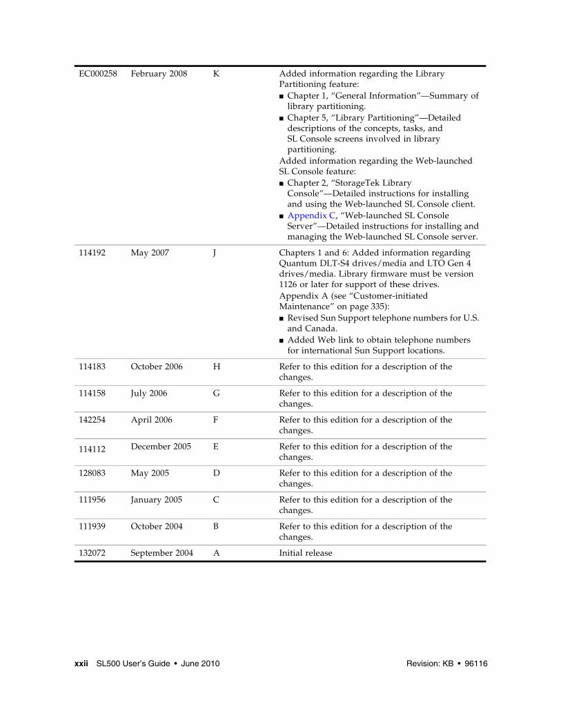
114192 May 2007 J Chapters 1 and 6: Added information regarding Quantum DLT-S4 drives/media and LTO Gen 4 drives/media. Library firmware must be version 1126 or later for support of these drives.Appendix A (see “Customer-initiated Maintenance” on page 335):■ Revised Sun Support telephone numbers for U.S.
and Canada. ■ Added Web link to obtain telephone numbers
for international Sun Support locations.
114183 October 2006 H Refer to this edition for a description of the changes.
114158 July 2006 G Refer to this edition for a description of the changes.
142254 April 2006 F Refer to this edition for a description of the changes.
114112 December 2005 E Refer to this edition for a description of the changes.
128083 May 2005 D Refer to this edition for a description of the changes.
111956 January 2005 C Refer to this edition for a description of the changes.
111939 October 2004 B Refer to this edition for a description of the changes.
132072 September 2004 A Initial release
96116 • Revision: KB xxiii
Preface
This User’s Guide is intended primarily for SL500 library system administrators and operators. It can also be used by Oracle StorageTek partners and support representatives.
Most of the information pertains to the library hardware, the StorageTek Library Console, and related operations. For specific drive information or for client application software commands, see the appropriate drive or software documentation.
Related DocumentationThe following lists contain the names and order numbers of publications that provide additional information about the product.
Oracle Welcomes Your CommentsOracle is interested in improving its documentation and welcomes your comments and suggestions. Submit your comments by clicking the Feedback[+] link at:
http://docs.sun.com
Please include the title and part number of your document with your feedback:
This chapter provides an overview of the major hardware components of the SL500 library and library specifications.
The library continues Oracle StorageTek’s approach to Information Lifecycle Management by providing a highly adaptable storage platform made to specifically consolidate, protect and retain customer information. The SL500 library protects a customer’s investments by providing a cost-effective entry point and makes it easy to grow the library with expansion modules. Whether customers have a small remote site or a corporate data center, they can feel secure that the SL500 library can accommodate all of their current and future data storage needs
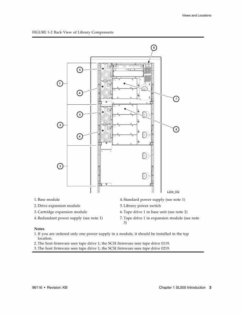
The library is a self-contained, fully automated tape cartridge storage system. It is scalable and mounts into a standard 483 mm (19 in.) rack. The SL500 is also available as a desk-top unit.
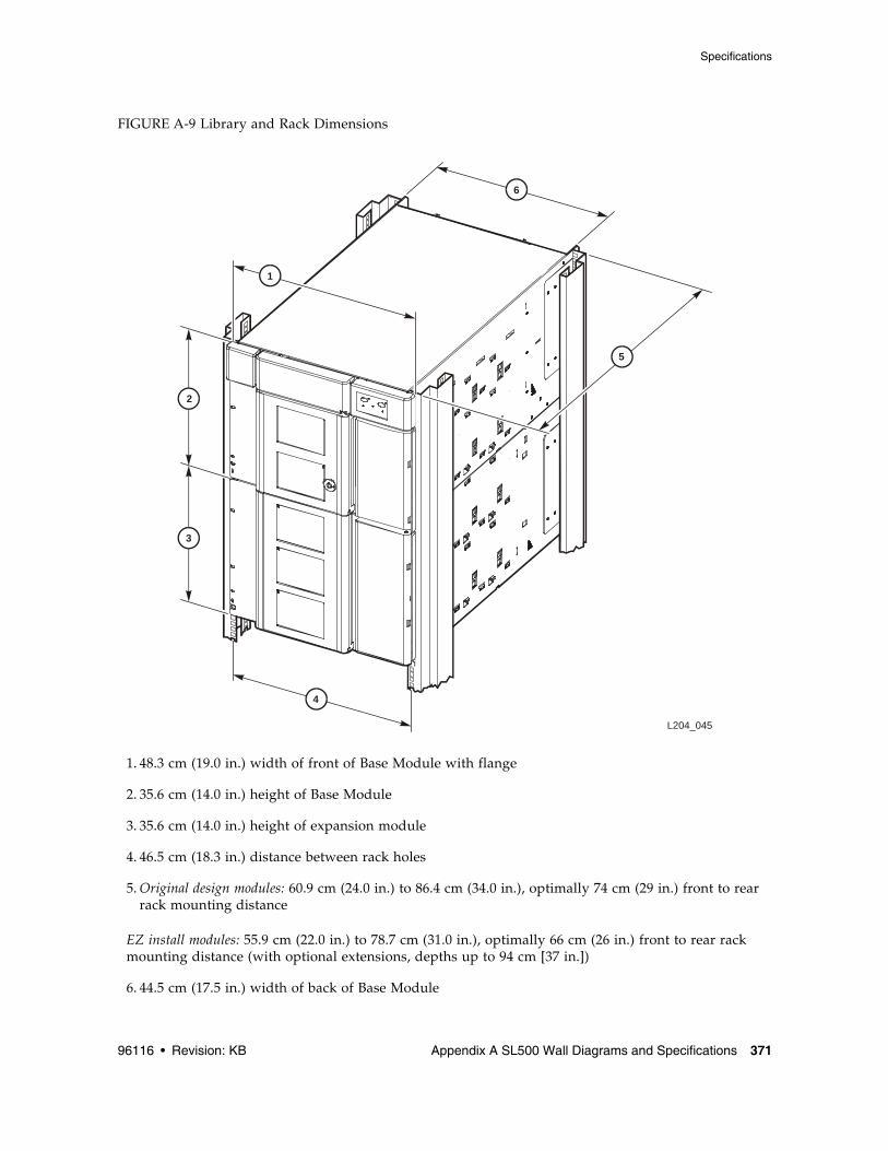
1. Base module 4. Standard power supply (see note 1)
2. Drive expansion module 5. Library power switch
3. Cartridge expansion module 6. Tape drive 1 in base unit (see note 2)
4. Redundant power supply (see note 1) 7. Tape drive 1 in expansion module (see note 3)
Notes1. If you are ordered only one power supply in a module, it should be installed in the top
location.2. The host firmware sees tape drive 1; the SCSI firmware sees tape drive 0119.3. The host firmware sees tape drive 1; the SCSI firmware sees tape drive 0219.
Caution – Firmware problems: You can not mix LTO and mixed-media arrays within the same library. If you add expansion modules, the new modules must have the same type arrays as the existing modules.
For each library:
■ The Base Module contains the robotics unit and the base unit:
■ The robotics unit has the robotic components and the keypad
■ The base unit has up to 50 storage cells (see note), one or two tape drives, and a five-cell cartridge access port (CAP).
Note – Only 30 of those storage cells can be used unless the cartridge upgrade conversion bill has been installed, allowing the other 20 storage cells to be used. With no upgrade, the first 30 storage cells after the reserved cells can be used for cartridge storage. If the reserved storage cells are configured for storage, the numbering starts there. The CAP cells also can be configured as storage cells.
■ Drive expansion modules and Cartridge Expansion Modules can be added to a standard rack to accommodate various storage cell and tape drive configurations.
Note – You must have a 50-cartridge capacity base unit, either from the initial order or with the upgrade conversion bill, before you can order an expansion module.
See Appendix A, “SL500 Wall Diagrams and Specifications” for detailed diagrams and dimensions.
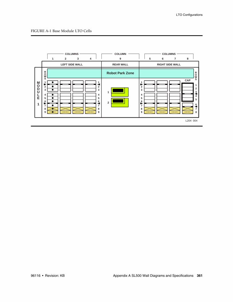
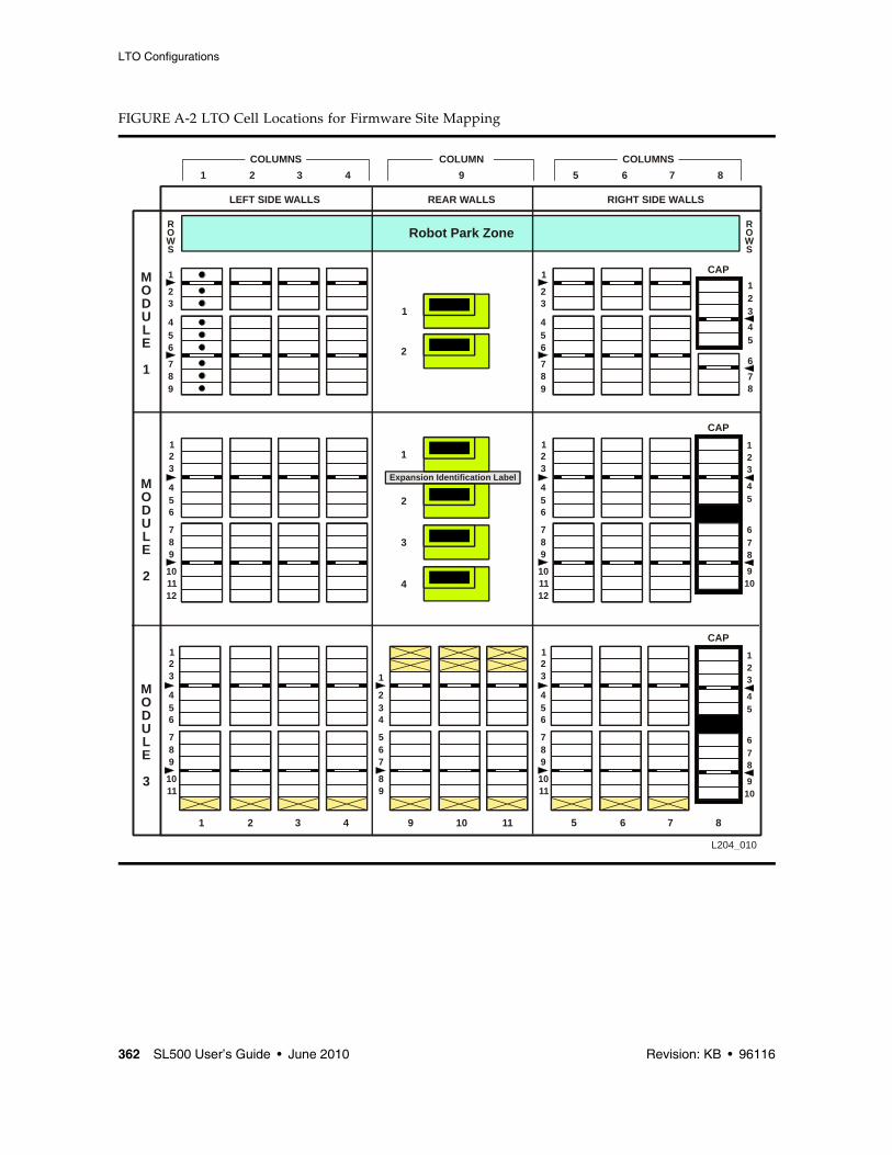
LTO Library Internal AddressingThe numbering scheme uses the library, module, row and column scheme. Four integers are used to represent the cartridge and tape drive slots, as viewed from the front of the library.
1. Library number (always 0)
2. Library module number 1 (top of rack) through 5 (bottom of rack)
3. Row number 1 through 9 (Base Module) or 1 through 12 (expansion module)
4. Column number 1 through 9 for Base Module and Drive Expansion Module, 1 through 11 for Cartridge Expansion Module See “LTO Storage Cell and Drive Capacities” on page 5 for more information.
Note – Your software might conflict with the following information. Refer to your software publication for unique information.
TABLE 1-1 shows the number of cartridge and tape drive slots available depending on the type and number of modules installed. The table assumes that, when DEMs and CEMs are installed in the same library, the DEMs are above all of the CEMs, as preferred.
Note – Do not install an EZ DEM below an original CEM. This is not physically allowed.
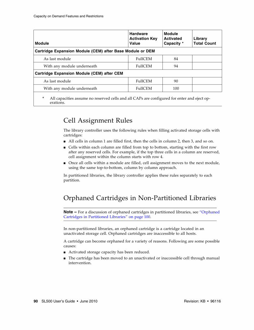
The following notes are factors that influence capacity:
1. When you add an expansion module below an existing module, you increase the capacity of the module directly above it by:
■ Base module: +16 storage cells
■ CEM (when another CEM is below it): +10 storage cells
■ DEM: +7 storage cells
2. When a CEM is installed below a Base Module or DEM, the top two rows on columns 9, 10, and 11 of the CEM are not accessible (-6 storage cells because the tape drives prevent the hand from reaching the cells).
3. The lowest module in the rack requires installation of the floor. The floor limits the distance the robot can travel, which makes the bottom row(s) in the lowest module inaccessible:
■ Base module: -16 storage cells
■ DEM: -7 storage cells
■ CEM (below another CEM): -16 storage cells (-10 storage cells on the lowest CEM, -6 storage cells on the CEM above it)
■ CEM (below Base Module or DEM): -16 storage cells
4. Cartridge access ports:
■ Base module: 5 storage cells (one magazine)
■ Each DEM: 10 storage cells (two magazines)
■ Each CEM: 10 storage cells (two magazines)
TABLE 1-1 LTO Storage Cell and Tape Drive Capacities
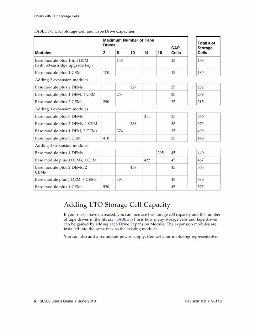
Adding LTO Storage Cell CapacityIf your needs have increased, you can increase the storage cell capacity and the number of tape drives in the library. TABLE 1-1 lists how many storage cells and tape drives can be gained by adding each Drive Expansion Module. The expansion modules are installed into the same rack as the existing modules.
You can also add a redundant power supply. Contact your marketing representative.
Base module plus 1 full DEM (with 50-cartridge upgrade key)
143 15 158
Base module plus 1 CEM 170 15 185
Adding 2 expansion modules
Base module plus 2 DEMs 227 25 252
Base module plus 1 DEM, 1 CEM 254 25 279
Base module plus 2 CEMs 290 25 315
Adding 3 expansion modules
Base module plus 3 DEMs 311 35 346
Base module plus 2 DEMs, 1 CEM 338 35 373
Base module plus 1 DEM, 2 CEMs 374 35 409
Base module plus 3 CEM 410 35 445
Adding 4 expansion modules
Base module plus 4 DEMs 395 45 440
Base module plus 3 DEMs, 1 CEM 422 45 467
Base module plus 2 DEMs, 2 CEMs
458 45 503
Base module plus 1 DEM, 3 CEMs 494 45 539
Base module plus 4 CEMs 530 45 575
TABLE 1-1 LTO Storage Cell and Tape Drive Capacities
Caution – Firmware problems: You can not mix LTO and mixed-media arrays and magazines within the same library. If you add expansion modules, the new modules must have the same type arrays as the existing modules.
Note – Your robotics unit must be part number 314558705 or higher to read SDLT cartridge labels.
For each library:
■ The Base Module contains the robotics unit and the base unit:
■ The robotics unit has the robotic components and the keypad
■ The base unit has up to 42 storage cells (see note), one or two tape drives, and a four-cell cartridge access port (CAP).
Note – The base unit can be ordered originally as a 24- or 42-cell unit. If you received the 24-cell version, only 24 of those storage cells can be used unless the upgrade conversion bill has been installed. Without a conversion bill, the first 24 cells after the reserved cells can be used for cartridge storage. If the reserved cells are configured for storage, the numbering starts with the first physical cell on the left.
An upgrade conversion bill allows the other 18 storage cells in the base unit to be used, for a total of 42. This conversion bill is for customers who want only the base unit and do not expect to order an expansion module.
The CAP cells can also be configured as storage cells.
■ Drive expansion modules (DEMs) and Cartridge Expansion Modules (CEMs) can be added to a standard rack to accommodate various storage cell and tape drive configurations.
Note – You must have a 42-cartridge capacity base unit before you can order an expansion module.
See Appendix A, “SL500 Wall Diagrams and Specifications” for detailed diagrams and dimensions.
Mixed-Media Library Internal AddressingThe numbering scheme uses the library, module, row and column scheme. Four integers are used to represent the cartridge and tape drive slots, as viewed from the front of the library.
2. Library module number 1 (top of rack) through 5 (bottom of rack)
3. Row number 1 through 8 (Base Module) or 1 through 10 (expansion module)
4. Column number 1 through 9 for Base Module and Drive Expansion Module, 1 through 11 for Cartridge Expansion Module
See “Mixed-Media Storage Cell and Drive Capacities” on page 8 for more information.
Mixed-Media Storage Cell and Drive Capacities
Note – Your software might conflict with the following information. Refer to your software publication for unique information.
TABLE 1-2 shows the number of cartridge and tape drive slots available depending on the type and number of modules installed. The table assumes that, when DEMs and CEMs are installed in the same library, the DEMs are above all of the CEMs, as preferred.
Note – Do not install an EZ DEM below an original CEM. This is not physically allowed.
Note – The following notes are factors that influence capacity:
1. When you add an expansion module below an existing module, you increase the capacity of the module directly above it by:
■ Base module: +14 storage cells
■ CEM (when another CEM is below it): +10 storage cells
■ DEM: +7 storage cells
2. When a CEM is installed below a Base Module or DEM, the top two rows on columns 9, 10, and 11 of the CEM are not accessible (-6 storage cells because the tape drives prevent the hand from reaching the storage cells).
3. The lowest module in the rack requires installation of the floor. The floor limits the distance the robot can travel, which makes the bottom row(s) in the lowest module inaccessible:
■ Base module: -14 storage cells
■ DEM: -7 storage cells
■ CEM (below another CEM): -16 storage cells (-10 storage cells on the lowest CEM, -6 storage cells on the CEM above it)
■ CEM (below Base Module or DEM): -16 storage cells
Adding Mixed-Media Storage Cell CapacityIf your needs have increased, you can increase the storage cell capacity and the number of tape drives in the library. TABLE 1-2 lists how many storage cells and tape drives can be gained by adding each Drive Expansion Module. The expansion modules are installed into the same rack as the existing modules.
You can also add a redundant power supply. Contact your marketing representative.
TABLE 1-2 Mixed-Media Storage Cell and Tape Drive Capacities
Modules
Maximum Number of Tape Drives
CAP Cells
Total # of Storage Cells 2 6 10 14 18
Base module 24 4 28
18-cartridge upgrade 42 4 46
Adding 1 expansion module
Base module plus 1 limited DEM 86 12 98
Base module plus 1 full DEM (with 33-cartridge upgrade)
Note – This section describes the controls and indicators that you can use to monitor and troubleshoot the library. For tape drive controls and indicators, refer to the vendor publications and Web sites.
Power SwitchWhen the switch (see FIGURE 1-2) is in the On position (1) the library and tape drives are powered-on. When the switch is in the Off position (0), the library and tape drives are powered-off.
Note – Earlier built libraries had power supplies that had individual power switches. Later libraries have one power switch that controls all power supplies in the rack.
Power Supply LEDThe following table describes the power supply LED.
Drive Tray LEDThe following table describes the drive tray LED.
KeypadThe keypad is used to:
TABLE 1-3 Power Supply LED
Activity Meaning Action
On Power supply is active. Nothing, this is normal.
Off The power supply failed. The service representative might need to replace the power supply.
The power supply is not receiving power.
The service representative might need to check the connections and voltages.
TABLE 1-4 Drive Tray LED
Activity Meaning Action
On solid The drive fan failed, the temperature is too high.
The service representative might need to replace the fan.
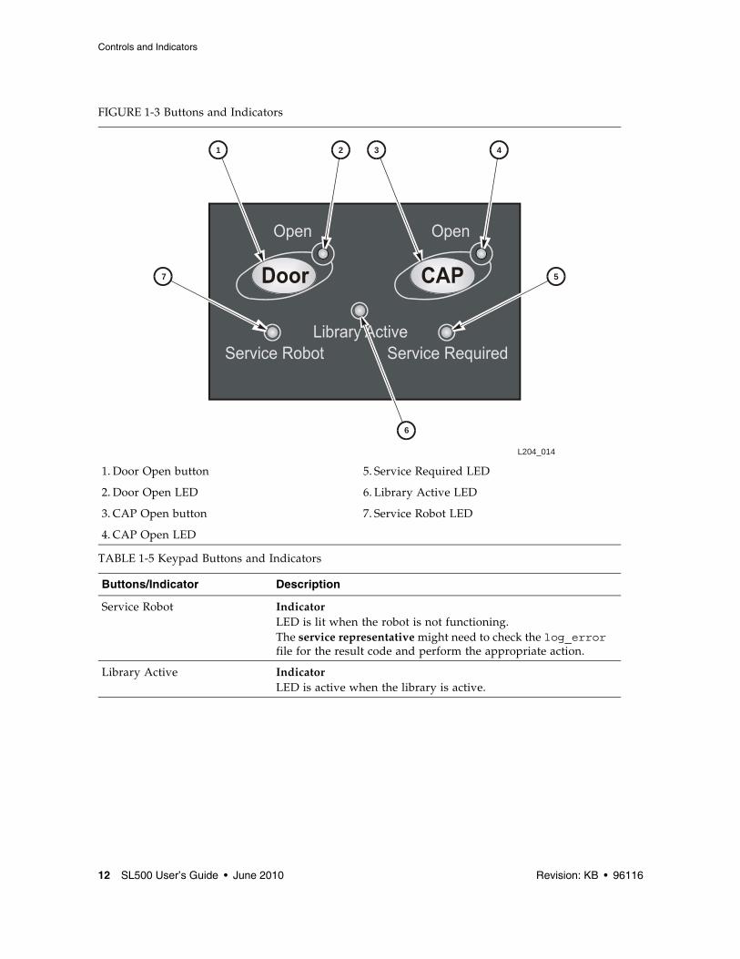
Service Robot IndicatorLED is lit when the robot is not functioning. The service representative might need to check the log_error file for the result code and perform the appropriate action.
Library Active IndicatorLED is active when the library is active.
Indicator■ LED is normally not lit.■ LED is lit when the library experiences a failure or is in a
non-ready state.
Open Door Indicator■ LED flashes amber when the Open Door button is pressed.■ LED is solid amber when the robot is parked in the robotics
unit.■ LED flashes during initialization and audit.■ LED is not lit when the library is ready for customer use.Button When pressed:1. Software allows the current job to complete. This could take a
while.2. Software retracts the robot into the robotics unit so that it will
not be damaged when you open the door with the key.
Open CAP Indicator ■ LED is amber when any CAP doors are open.■ LED is not lit when all CAP doors are shut.Button Button is used to open all CAP doors in a rack.
TABLE 1-6 Keypad Service Required LED
Activity Meaning Action
Flashing The redundant component failed. The service representative might need to replace the failed redundant component, such as power supply, tape drive, or fan.
Diagnostics are running. Nothing, this is normal.
Diagnostics failed. The service representative might need to check the log_error file for the result code and perform the appropriate action.
Door is open. Close and lock the door.
On solid The non-redundant component failed. This includes the last working component of a redundant set of components, such as tape drives.
The service representative might need to check the log_error and log_warning files to determine which component failed, and replace the failed component.
The library has stopped operating. The service representative might need to check the log_error file for the result code and perform the appropriate action.
TABLE 1-5 Keypad Buttons and Indicators (Continued)
■ Hewlett-Packard LTO Gen 2, 3 and 4 (check availability for Gen 4) SCSI low voltage differential (LVD) and Fibre Channel (FC)
■ IBM LTO Gen 2, 3 and 4 (check availability for Gen 4) SCSI LVD and FC
■ Quantum SDLT tape drives:
■ SDLT 320 SCSI LVD
■ SDLT 600 SCSI LVD and FC
■ DLT-S4 SCSI and FC
Tape drives are hot-swappable. This means they can be replaced without removing power from the library, as longer as the following actions are done:
■ Back up the server before removing the tape drive.
■ If the tape drives are daisy-chained, stop all data processing on the channel to which the tape drives are connected before disconnecting the tape drives.
■ Make sure that there is no activity on the SCSI bus before disconnecting the external SCSI cables. Stop all processes on the host.
■ Make sure that all signals are terminated at each end of the SCSI bus.
■ If your external SCSI cables are long enough that they do not interfere with removing and replacing the tape drives, you can swap tape drives without disconnecting the external SCSI cables. If so, disregard the steps to remove those cables.
Caution – Possible data loss or system problem: If you must disconnect the external SCSI cables, make sure that you quiesce the system first (stop all processes on the tape drives on the SCSI bus with the tape drive you are replacing).
All tape drives are mounted on SL500-unique tray assemblies. Each assembly contains the:
■ Tape drive
■ +5 VDC fan
■ RLD tape drive interface card
Drive tray assemblies are installed in slots (also called bays), accessible from the back of the library. When a tape drive is inserted into the assigned slot, it connects to the RLD card by way of a cable. The RLD card connects directly to the RLM or RLE (Drive Expansion Module) backplane through a blind-mate connector.
Note – If a slot does not contain a tape drive, a vacancy plate must be installed over the slot.
Note – LTO technology was developed by IBM, Hewlett-Packard, and Seagate. LTO is an “open format’ technology, which means that users have multiple sources of product and media.
This section discusses media compatibility and cartridge labels. For all other tape drive and media information, such as specifications, refer to:
■ The specific vender Web site
■ http://www.sun.com/storagetek/index.jsp
For best results, match the cartridges with the specific drive type (for example, use LTO 2 cartridges in Gen 2 drives):
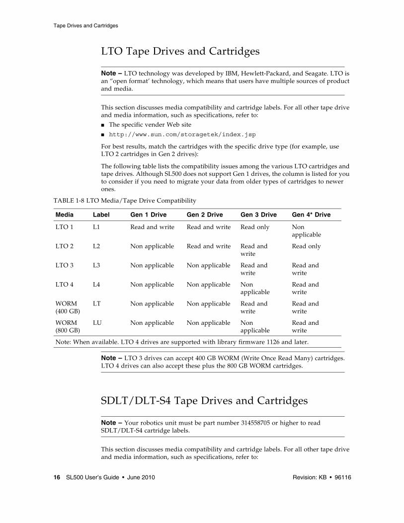
The following table lists the compatibility issues among the various LTO cartridges and tape drives. Although SL500 does not support Gen 1 drives, the column is listed for you to consider if you need to migrate your data from older types of cartridges to newer ones.
Note – LTO 3 drives can accept 400 GB WORM (Write Once Read Many) cartridges. LTO 4 drives can also accept these plus the 800 GB WORM cartridges.
SDLT/DLT-S4 Tape Drives and Cartridges
Note – Your robotics unit must be part number 314558705 or higher to read SDLT/DLT-S4 cartridge labels.
This section discusses media compatibility and cartridge labels. For all other tape drive and media information, such as specifications, refer to:
TABLE 1-8 LTO Media/Tape Drive Compatibility
Media Label Gen 1 Drive Gen 2 Drive Gen 3 Drive Gen 4* Drive
LTO 1 L1 Read and write Read and write Read only Non applicable
LTO 2 L2 Non applicable Read and write Read and write
Read only
LTO 3 L3 Non applicable Non applicable Read and write
Read and write
LTO 4 L4 Non applicable Non applicable Non applicable
Read and write
WORM (400 GB)
LT Non applicable Non applicable Read and write
Read and write
WORM (800 GB)
LU Non applicable Non applicable Non applicable
Read and write
Note: When available. LTO 4 drives are supported with library firmware 1126 and later.
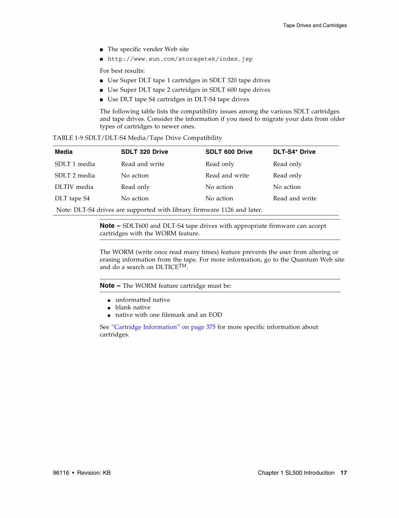
■ Use Super DLT tape 1 cartridges in SDLT 320 tape drives
■ Use Super DLT tape 2 cartridges in SDLT 600 tape drives
■ Use DLT tape S4 cartridges in DLT-S4 tape drives
The following table lists the compatibility issues among the various SDLT cartridges and tape drives. Consider the information if you need to migrate your data from older types of cartridges to newer ones.
Note – SDLT600 and DLT-S4 tape drives with appropriate firmware can accept cartridges with the WORM feature.
The WORM (write once read many times) feature prevents the user from altering or erasing information from the tape. For more information, go to the Quantum Web site and do a search on DLTICETM.
Note – The WORM feature cartridge must be:
■ unformatted native■ blank native■ native with one filemark and an EOD
See “Cartridge Information” on page 375 for more specific information about cartridges.
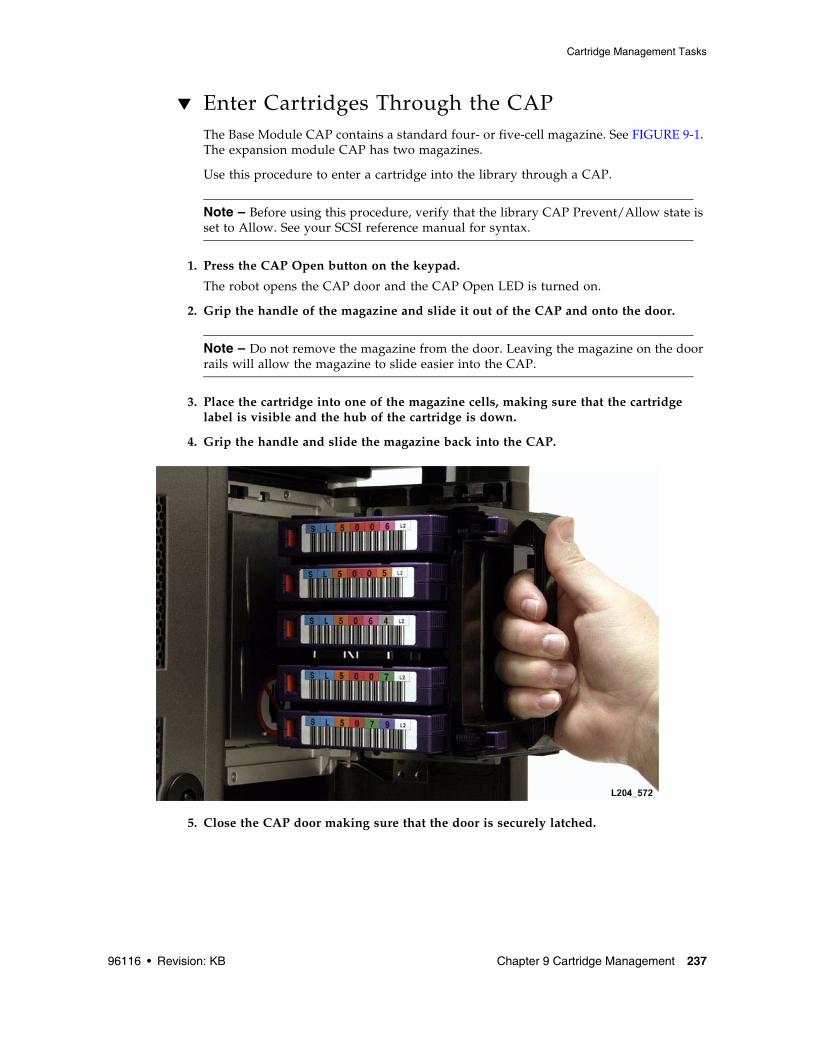
Cartridge Access PortsThe cartridge access ports (CAPs) can be used to add cartridges to the library, or remove cartridges from the library without interrupting normal robotic operation.
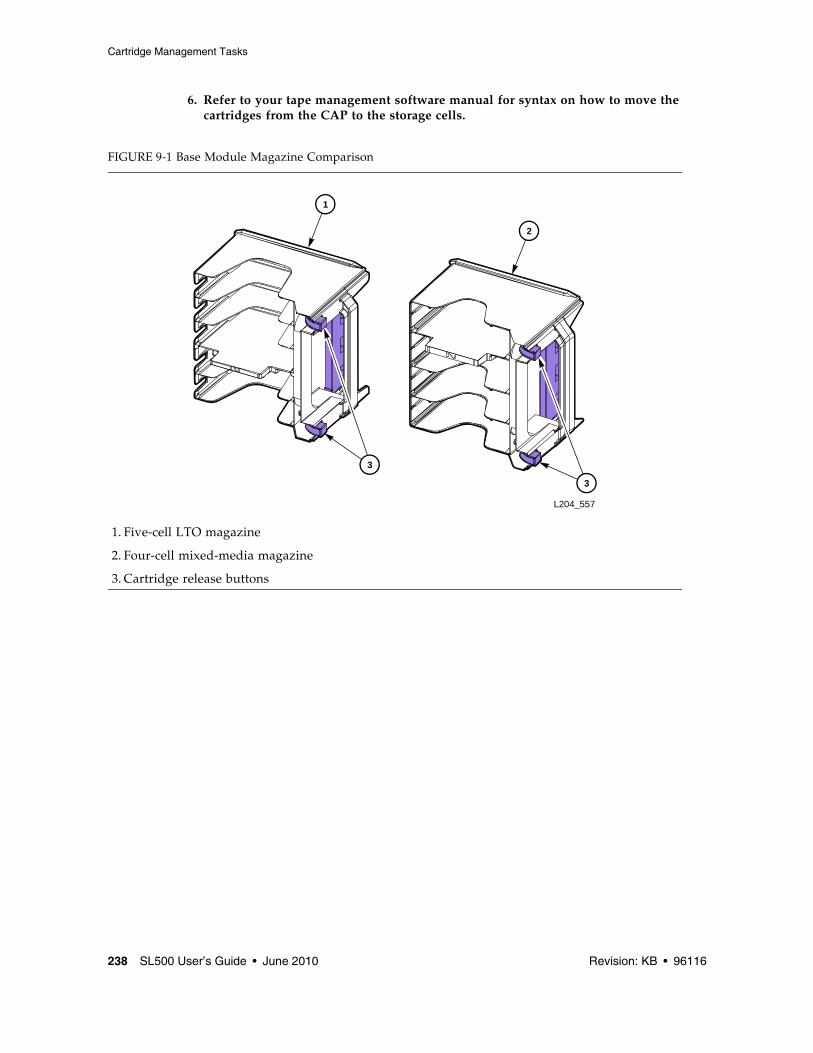
■ The CAP in the Base Module has one five-cell magazine.
■ The CAP in the Drive Expansion Module has two five-cell magazines.
Although the CAPs are not physically connected, they are logically connected. If any of the CAPs are open, the CAP LED on the keypad will be on, alerting the operator to take action to close the CAP. If all of the CAPs are closed, the CAP LED will be off.
You can use the keypad on the robotics unit to issue a command for the robot to unlock the CAP.
The CAP has two settings, ALLOW and PREVENT. ALLOW is the default setting after you power-on or reset the library. The following table shows how these settings affect the CAPs. For CAP LED indicator information see “Controls and Indicators” on page 10.
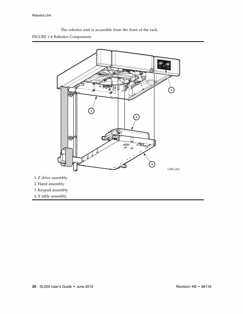
Robotics UnitThe robotics unit provides movement of cartridges among the storage cells, tape drives, and cartridge access ports (CAPs). The three main robotic components are, as shown in FIGURE 1-4:
■ Z drive assembly
■ X table assembly
■ Hand assembly
The Z drive assembly uses the Z drive pulley to move the X table up and down to the desired storage cell or tape drive. At the same time, the X carriage assembly (containing the hand) moves the hand forward and backward; the wrist motor rotates the hand right and left.
CAP Condition ALLOW PREVENT
All of the CAPs are closed When you press the CAP button all of the CAPs in the rack will open.The library firmware turns on the CAP LED.
When you press the CAP button, the action is ignored and all of the CAPs remain closed.
Any of the CAPs are open When you press the CAP button, any CAP that is not open in the rack will open.
When you press the CAP button, the action is ignored and all of the CAPs remain in their individual current state of open or closed.
The hand assembly contains the wrist hub assembly, gripper assembly, and bar-code scanner. The gripper assembly has fingers that grasp the sides of the cartridge. If the library loses power while a cartridge is between the fingers, the manual release screw is used to remove the cartridge. A worm gear can be used to rotate the hand to the correct position to access the manual release screw.
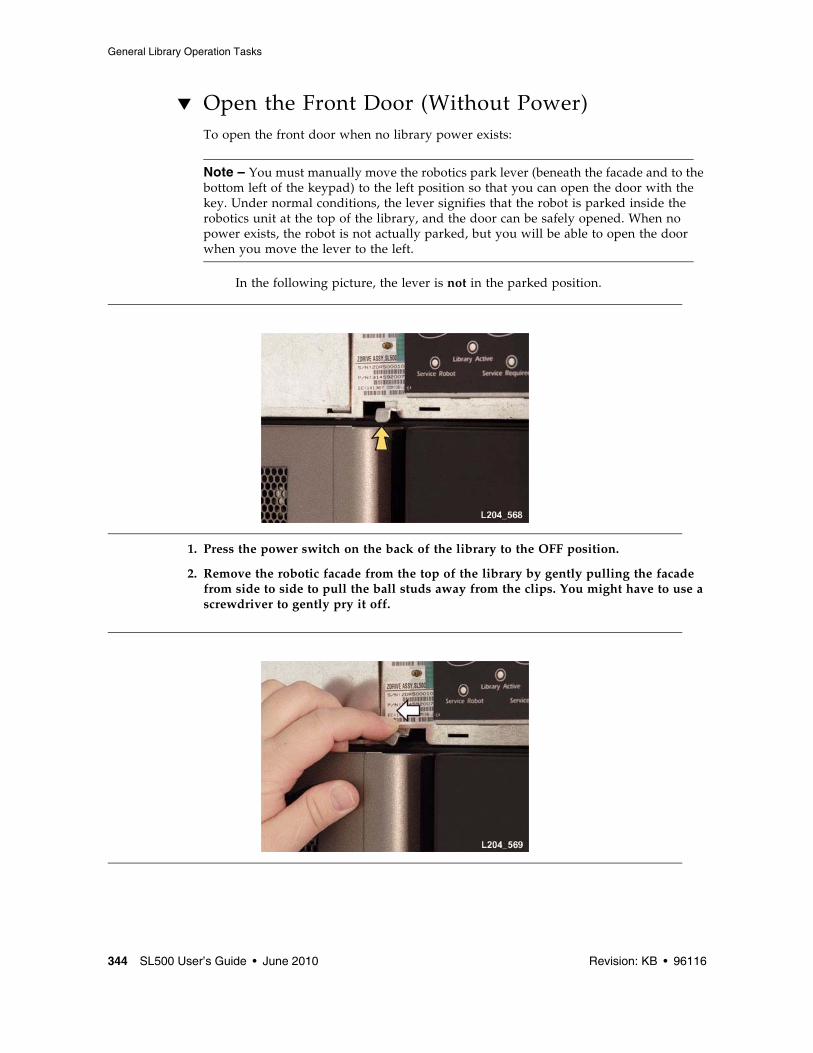
For safety purposes, the robotics will be “parked” in the robotics unit when the front door is opened or when the Open Door button is pressed on the keypad. Parked means that the robotics components are fully retracted into the robotics unit at the top of the library. To verify the robot is parked, look at the lever in the cutout beneath the facade and to the bottom left of the keypad, the lever should be to the left.
Power SystemThe base unit has one standard power supply. A second supply can be ordered and installed to provide redundant power to the module components. Each supply should be plugged into a separate circuit and powered-on to provide redundant power. If one supply fails, the second supply automatically provides power.
A single power switch on the back of the library is used to power-on or power-off all the power supplies in the rack:
■ The ON position is 1.■ The OFF position is 0.
Cooling The fans provide cooling for the library electronics. The tape drives and power supplies contain their own fans.
ElectronicsThe electronics consist of the control path and robotic cards in the base unit.
Communications include:
■ Command line interface (CLI) over an RS232 port
■ Public Ethernet port (The private port is for future use)
■ Point to point library/tape drive RS423 interface
■ Control path card for LVD SCSI or SCSI over Fibre Channel
Sensors include:
■ Card temperature
■ Fan operational
■ Power safe
■ Tape drive present
■ Tape drive fault LED
RLC CardThe RLC card is the processor card. It contains all the necessary hardware to maintain the robotics, interfaces, servo and vision control, and the door/CAP sensor status.
The card stores the library capacity information and the volume serial numbers (also called VOLID) of the cartridges in the library storage cells.
Interface CardsThe RLW card is the LVD SCSI interface card. The MPU2 card is the Fibre Channel interface card.
Safety FeaturesThe following subsections describe the safety features that are incorporated into the library.
Cards and Power SupplyThe RLC card, SCSI (MPW/RLW) or Fibre Channel (MPU2) interface card, and the power supply are housed inside protective modules to prevent you from coming into contact with hazardous voltages and sensitive electronics.
RoboticsThe software parks the robot by retracting it into the robotics unit module before the front door can be opened to prevent the robot from being damaged.
When the front door is opened, power is removed from the robot.
Front DoorThe front door must be opened with a key to ensure that the data is secure. If the door is not fully closed, a sensor relays the condition to the software and the robot remains disabled.
■ Library control path support for LVD SCSI or SCSI over Fibre Channel
■ Data path for a single-port SCSI or dual-port Fibre Channel tape drive
■ Cartridge access ports and sensors for indicating a door open or closed condition
■ Front door opened button (on keypad), key for opening door, sensor LED that indicates door is closed and latched.
■ Public 100BaseT Ethernet Port for the StorageTek Library Console (SL Console) and remote service access (see FIGURE 1-6 and “StorageTek Library Console” on page 27).
Note – Currently, only one RLC card is available.
FIGURE 1-6 Library Interfaces Locations
1. Private Ethernet port is for future use.
2. Eject OK (hot-swappable) LED, when on, indicates that the RLC card can be removed. (See note below.)
3. Public Ethernet port is for remote service access, SL Console, and SNMP (future)
4. Fault LED indicates that the controller has detected a problem.
5. Reserved for future use.
6. Standby LED, when lit, indicates the RLC card (when two RLC cards are installed) is in standby mode. (See note below.)
7. CLI port is an RJ-45 serial port for service representatives.
8. Active LED, when lit, indicates this RLC card is active if two RLC cards are installed. If only one card is installed, the LED is always on. (See note below.)
Tape Management SoftwareThe tape management software provides the instructions to perform tape read and write operations and robotic move operations. When the library is in automated mode, these operations occur without manual intervention. The software determines where the cartridge is located by accessing audit data uploaded from the library. The software then allocates the tape drive to receive the cartridge.
For command descriptions and instructions, refer to your software publications.
Introduction The StorageTek Library Console (SL Console) is a Java-based software application that provides a graphical user interface (GUI) for monitoring and managing the StorageTek library.
Following are some of the activities you can perform with the SL Console:
■ Manage available library storage capacity
■ Manage and configure library partitions (optional feature)
■ View and modify status and properties of the library and associated devices (drives, CAP, robots, and elevators)
■ Perform an audit on all or part of the library
■ Perform a self-test on the library or an associated device
■ Perform a diagnostic move (exercise a robot)
■ Locate a cartridge
■ Move a cartridge from one location to another
■ Display library logs
■ Display error explanations
■ Download new library firmware while the library is in operation
■ Display context-sensitive help
SL Console ModesDepending on your needs, you can run the SL Console in any of the following modes. For details and procedures, see:
SL Console Security Security features built into the SL Console control both user authentication and user authorization. The security features include:
■ User IDs – User IDs control user authentication. Each user must have a valid, active user ID and password to log in to the SL Console.
■ Access permissions – Access permissions control user authorization. Each user ID is assigned a set of access permissions, which determine the types of requests the user can submit through the SL Console. For example, in order to modify the system properties of a drive, a user must log in with a user ID that has the proper access permissions.
When you log in to the SL Console with a valid user ID, password, and library name, the system authenticates your identity and then authorizes your access to the various SL Console functions.
User IDsTo log in to the SL Console, you must have a valid, active user ID. Each user ID must be assigned a password.
There are a fixed set of user IDs at a site. The user IDs include admin (customer administrator), service (Oracle Customer Services Engineer), and oem (third-party field service technician). When you log in successfully, the SL Console displays your user ID in the status bar of the screen.
Any number of users can connect to a library through the standalone SL Console or Web-launched SL Console.
Activation Password Before any users at your site can use the SL Console for the first time, your library administrator must activate the “admin” userid with a special activation password. Your Oracle support representative provides your administrator with the activation password, which is valid for one-time use only.
After logging in with the activation password, the administrator must change the admin user ID password to ensure system security.
For details about this process, see the appropriate library Installation Guide.
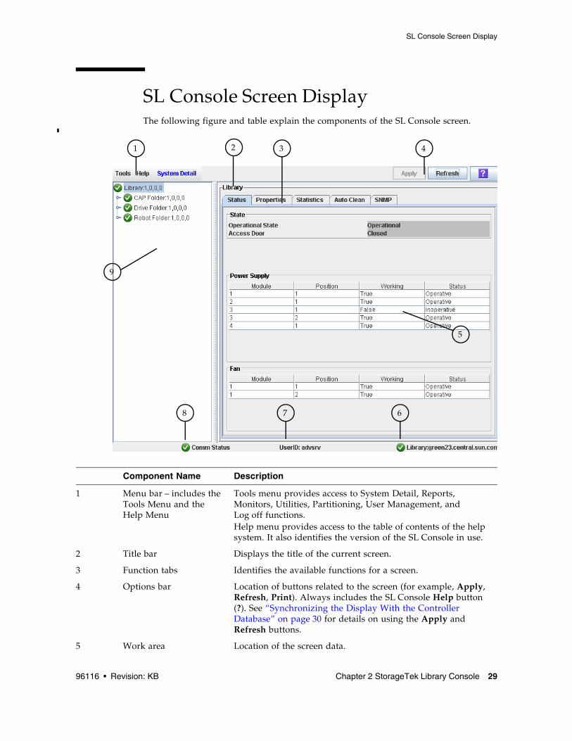
SL Console Screen Display The following figure and table explain the components of the SL Console screen.
Component Name Description
1 Menu bar – includes the Tools Menu and the Help Menu
Tools menu provides access to System Detail, Reports, Monitors, Utilities, Partitioning, User Management, and Log off functions. Help menu provides access to the table of contents of the help system. It also identifies the version of the SL Console in use.
2 Title bar Displays the title of the current screen.
3 Function tabs Identifies the available functions for a screen.
4 Options bar Location of buttons related to the screen (for example, Apply, Refresh, Print). Always includes the SL Console Help button (?). See “Synchronizing the Display With the Controller Database” on page 30 for details on using the Apply and Refresh buttons.
Note – This feature is available starting with SL Console version FRS_3.30. It is available on selected screens only.
You can modify the layout and display of selected SL Console screens as follows.
Synchronizing the Display With the Controller Database
Logging InThe SL Console gets all library configuration data from the library controller. Therefore, you should be careful when logging in to the SL Console before the library has fully initialized. You may see warnings that configuration data is not yet available, in which case you need to exit and log in again at a later time. Additionally, if a library audit is performed as part of initialization, until the audit is complete, any configuration data displayed may not be completely up-to-date and accurate.
Making Library Configuration UpdatesWhen you first bring up an SL Console screen, the display reflects the most recently saved data from the library controller database. If you use the screen to modify the library contents or configuration, your changes do not update the controller database until you commit your changes by clicking the Apply button. Multiple users can access the library at the same time, using the SL Console, command line interface, and various
6 Library health indicator Identifies the library to which the SL Console is connected, and displays a graphical representation of the library health.
7 UserID indicator Displays the user ID currently logged in to the SL Console.
8 Server communication health indicator
Displays a graphical heartbeat monitor indicating the state of server communication health.
9 Device tree Lists the devices included in the library.
Display Option Instructions
Sort the display by any column
Click the heading of the column you want to sort by. Initially the sort is in ascending order. Click the heading again to switch between ascending and descending order.
Arrange the columns in any order
Click and drag a column heading horizontally to any position in the heading row.
Resize the columns Click the border of the column heading and drag it left or right to change the column width.
host applications to make their own changes to the library contents and configuration. If other users make changes and apply them to the controller database, you will not see these changes until you click Apply or Refresh on your screen. Therefore, the display you see on the SL Console may not reflect the actual saved library configuration at a given point in time.
For these reasons, if you are making major modifications to the library configuration – adding modules, defining partitions, etc. – it is important that you coordinate these changes with other library users. Failure to do so could result in conflicts within the controller database.
SL Console Reports The SL Console library reports provide information on the library and its associated devices (for example, drives, robots, and CAPs), events, and tape cartridges. You can use the reports to monitor library activity and identify potential problems. In addition to displaying the reports on-screen, you can save the report data to a file, which you can then print or include in e-mail.
All report output is a static display of information sent from the library controller at the time the report is generated. The SL Console does not update the information dynamically unless you explicitly select the Update button on the Options bar.
Note – Running multiple instances of the standalone SL Console or Web-launched SL Console on the same PC or workstation can cause problems such as inconsistent data on reports. It is recommended that only one user at a time produce SL Console reports on a PC or workstation, unless all instances of the SL Console are the same version.
Report TypesThe SL Console provides the following types of reports:
■ Log – detailed system event logs
■ Statistics – statistical information on library operations
■ Status Detail – details on the status of the library and associated devices, such as CAPs, drives, and robots
■ Status Summary – summary information on the status of the library and associated devices
■ Version – details about library hardware and software versions
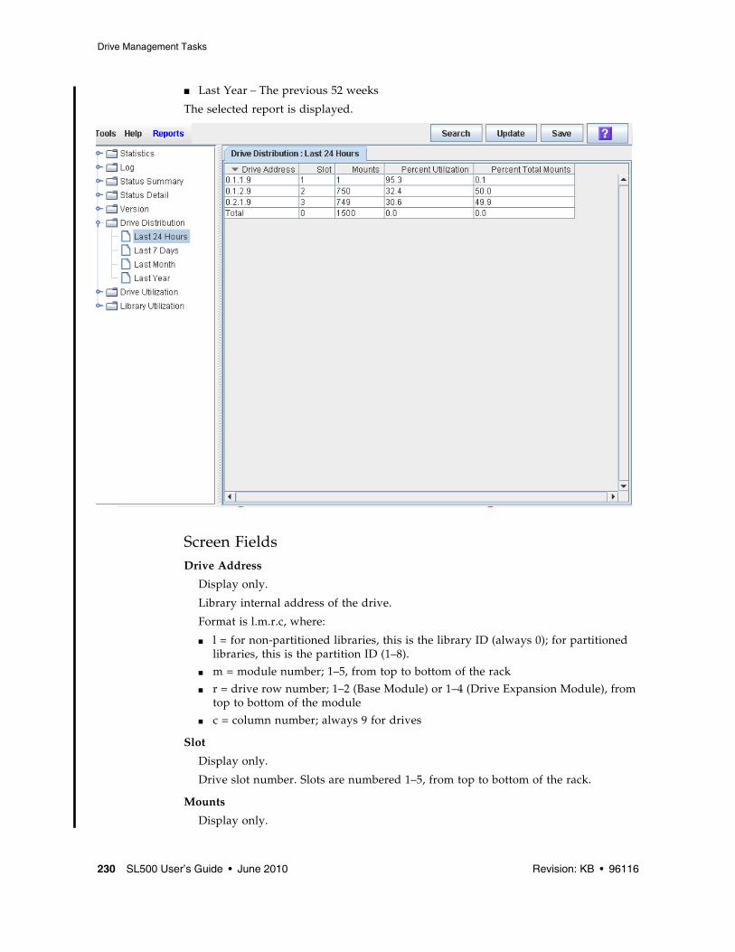
■ Drive Distribution – statistical summary of cartridge mount activity for a selected time period.
■ Drive Utilization – statistical summary of cartridge mount activity for a selected time period, broken into regular time intervals
■ Library Utilization – statistical summary of library activity for a selected time period.
Report Options BarThe Options bar on each report allows you to perform the following functions:
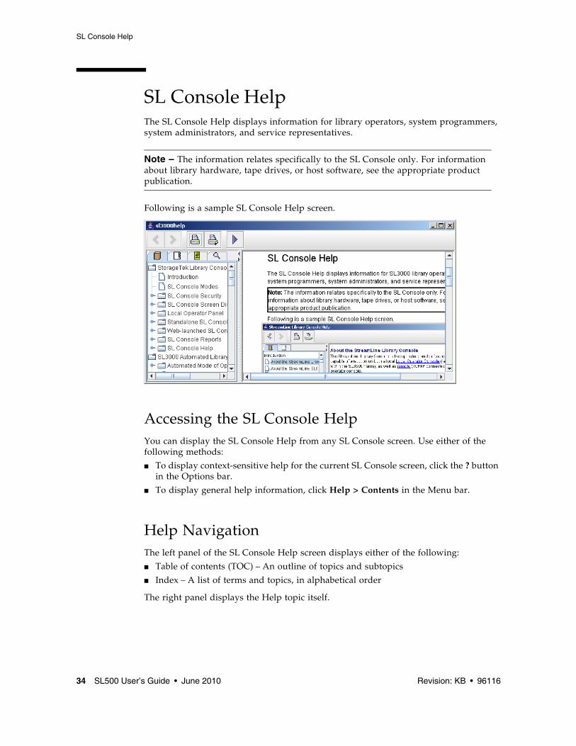
SL Console Help The SL Console Help displays information for library operators, system programmers, system administrators, and service representatives.
Note – The information relates specifically to the SL Console only. For information about library hardware, tape drives, or host software, see the appropriate product publication.
Following is a sample SL Console Help screen.
Accessing the SL Console Help You can display the SL Console Help from any SL Console screen. Use either of the following methods:
■ To display context-sensitive help for the current SL Console screen, click the ? button in the Options bar.
■ To display general help information, click Help > Contents in the Menu bar.
Help NavigationThe left panel of the SL Console Help screen displays either of the following:
■ Table of contents (TOC) – An outline of topics and subtopics
■ Index – A list of terms and topics, in alphabetical order
The top of the SL Console Help screen includes the following navigation buttons.
Tips for Using the SL Console Help■ You can minimize, maximize, or resize the Help screen to accommodate your needs.
■ You can resize the left and right panels of the Help screen by clicking the border between them and dragging it left or right.
■ Most topics include a Related Topics button at the bottom of the page. Click on this button to display and navigate to help topics containing related information.
Button Action
Back Retraces your steps, going backward one topic at a time.
Forward Retraces your steps, going forward one topic at a time.
Print Displays the Print popup, which allows you to print one or more topics:■ To print the current topic, click the Print button.■ To print a different topic, click the topic title in the
SL Console Help table of contents, and click the Print button.■ To print more than one topic, highlight the topics in the
SL Console Help table of contents by pressing Shift-Click or Ctrl-Click, and then click the Print button.
Print Setup Displays the Page Setup popup, which allows you to modify your print page layout.
TOC Displays the SL Console Help table of contents.
Web-launched SL ConsoleThe Web-launched SL Console is a standard feature of the library. It enables the SL Console to be installed on a centralized Web server. Individual clients can then use a supported Web browser to download the Web-launched SL Console. Using the Web-launched SL Console you can connect to any library for which you have a valid user ID.
The Web-launched SL Console is delivered to clients as a Java Web Start process, which executes outside the browser.
Security ConsiderationsThe Web-launched SL Console software is digitally signed, which guarantees that it has been issued by Oracle Corporation and has not been altered or corrupted since it was created. As a Java Web Start process, the Web-launched SL Console includes the security features provided by the Java 2 platform.
The customer is responsible for implementing all appropriate additional security systems, including firewalls, user access, etc.
Client RequirementsYou can download the Web-launched SL Console to clients meeting the following requirements:
Web-launched SL Console UpdatesUpdates to the Web-launched SL Console only need to be installed on the centralized Web server. Once the updates are installed on the server, they are downloaded automatically to all clients whenever the application is started on the client.
Platform Solaris 9 – SPARC (Firefox 2.x)Solaris 10 – SPARC (Firefox 2.x)Windows 2000 – 32 bit (IE 5, IE 5.5, Firefox 2.x)Windows XP – 32 bit (IE 6, IE 7, Firefox 2.x)Windows Vista – 32 bit (IE 7, Firefox 2.x)
Other ■ Java 1.5 Plug-in (the browser will install this automatically if it is not present already)
■ Ethernet connection to the library■ Ethernet connection to the Web-launched SL Console
Starting the Web-launched SL Console on a ClientYou can use either of the following methods to start and log in to the Web-launched SL Console on a client:
■ From a command line (Solaris only) or supported browser. See “Log in to the Web-launched SL Console Using a Browser or Command Line” on page 42.
■ By double-clicking the slc.jnlp icon on your client. In order to use this method from a client, you must use the browser method at least once and save the slc.jnlp file locally. See “Log in to the Web-launched SL Console Using an Icon” on page 47.
Standalone SL Console The standalone SL Console is a standard feature of the StorageTek library. It enables you to run the SL Console application remotely from a PC or workstation that has a network connection to the library. Using the standalone SL Console you can connect to any library for which you have a valid user ID.
Security ConsiderationsThe SL Console application interfaces with the primary library interface (PLI) over a security software layer (SSL). The SSL provides a secure communication path between the library and the customer’s SL Console; sessionthis prevents an unauthorized network user from monitoring library activity.
Installation RequirementsYou can install the standalone SL Console on a computer meeting the following requirements:
The standalone SL Console software is available for download at the following Oracle Corporation sites:
Note – You must have a valid login ID and password for the download site you are using. Contact your Oracle support representative for assistance.
Platform Solaris 9 – SPARCSolaris 10 – SPARCWindows 2003 Server – 32 bitWindows XP Client – 32 bitWindows Vista – 32 bit
Note – Before you can install a new version of the standalone SL Console, you must uninstall the previous version. See your PC or workstation documentation for detailed instructions. Running multiple versions of the SL Console on the same PC or workstation can cause problems such as inconsistent data on reports.
Once you have uninstalled the previous version of the SL Console, see the following procedures for detailed instructions on upgrading the software.
■ “Download the Standalone SL Console Installer” on page 63
▼ Log in to the Web-launched SL Console Using a Browser or Command Line
Note – Before you perform this activity, you must obtain the DNS alias or IP address of the SL Console server. Depending on how your Web-launched SL Console server has been set up, it may be accessible only by IP address. See your library administrator for assistance.
Note – The command line option is available on Solaris platforms only.
On Windows 2000, you may need to install a Java plugin for your Web browser before performing this procedure. You can download the plugin from the following location: http://java.sun.com/products/archive/j2se/5.0_04/index.html
On Solaris platforms, it is easier to log in to the Web-launched SL Console using the command line. If you prefer to log in using a Web browser, however, you need to download a recent version of the Firefox Web browser from the following location: www.mozilla.com
1. Choose your login method:
■ Command line – available on Solaris only. Proceed to Step 2.
■ Web browser – available on either Windows or Solaris. Proceed to Step 3.
2. Open a terminal window, and type the following command:
javaws http://server_ID:port_ID/opel/slc.jnlp
where:
■ server_ID is either of the following:
■ IP address of the SL Console server (in nnn.nnn.nnn.nnn format)
■ DNS alias of the SL Console server
■ port_ID is the port ID of the SL Console application, typically 8080
■ opel is the name (context root) of the Web-launched SL Console application on the server.
Proceed to Step 4.
3. Start a supported Web browser on your client PC or workstation (see “Client Requirements” on page 36 for a list of supported browsers), and in the Location Bar or Address field, enter the URL of the SL Console Web Start application:
http://server_ID:port_ID/opel
where:
■ server_ID is either of the following:
■ IP address of the SL Console server (in nnn.nnn.nnn.nnn format)
■ DNS alias of the SL Console server
■ port_ID is the port ID of the SL Console application; typically 8080
■ opel is the name (context root) of the Web-launched SL Console application on the server.
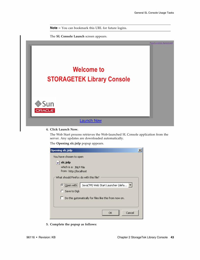
a. Specify the action you want to take with the slc.jnlp file:
■ Click the Open with Java(TM) Web Start Launcher radio button if you want to start the SL Console directly.
■ Click the Save to Disk radio button if you want to save the slc.jnlp file to your client and log in to the SL Console later. See “Log in to the Web-launched SL Console Using an Icon” on page 47 for login instructions.
b. Optionally click the “Do this automatically for files like this from now on” checkbox. If you make this selection, this popup will not appear during future logins.
c. Click OK.
If this is the first time you are running the Web-launched SL Console, a digital signature warning popup appears.
6. Complete the popup as follows:
a. Verify the Publisher.
b. Optionally click the “Always trust content from the publisher” checkbox. If you make this selection, this popup will not appear during future logins.
▼ Log in to the Web-launched SL Console Using an Icon
Note – In order to perform this activity, you must first save the Web-launched SL Console slc.jnlp file to your client. See “Log in to the Web-launched SL Console Using a Browser or Command Line” on page 42 for details.
1. Double-click the slc.jnlp desktop icon on your client.
The Web Start process retrieves the Web-launched SL Console application from the server. Any updates are downloaded automatically.
The Web Start process retrieves the Web-launched SL Console application from the server. Any updates are downloaded automatically.
If this is the first time you are running the Web-launched SL Console, a security warning popup appears.
3. Complete the popup as follows:
a. Verify that the Publisher is Oracle Corporation
b. Optionally click the “Always trust content from the publisher” checkbox. If you make this selection, this popup will not appear during future logins.
Note – Before you log off, make sure all operations for the current SL Console session have completed (for example, code loads, audits, diagnostic moves).
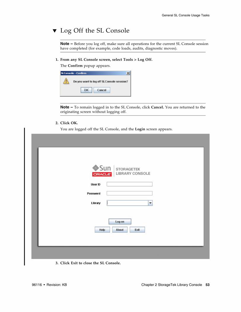
1. From any SL Console screen, select Tools > Log Off.
The Confirm popup appears.
Note – To remain logged in to the SL Console, click Cancel. You are returned to the originating screen without logging off.
2. Click OK.
You are logged off the SL Console, and the Login screen appears.
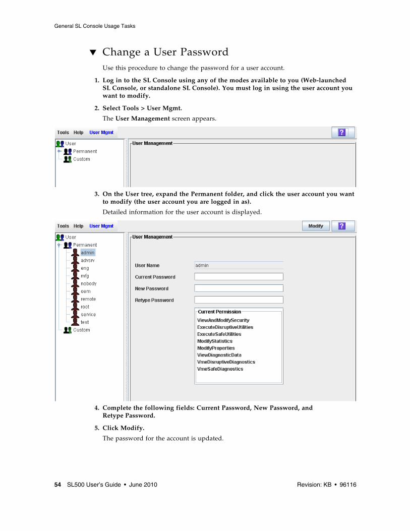
▼ Change a User Password Use this procedure to change the password for a user account.
1. Log in to the SL Console using any of the modes available to you (Web-launched SL Console, or standalone SL Console). You must log in using the user account you want to modify.
2. Select Tools > User Mgmt.
The User Management screen appears.
3. On the User tree, expand the Permanent folder, and click the user account you want to modify (the user account you are logged in as).
Detailed information for the user account is displayed.
4. Complete the following fields: Current Password, New Password, and Retype Password.
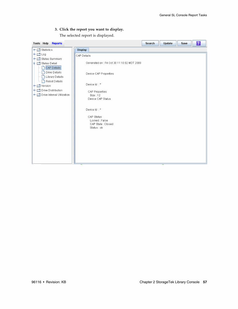
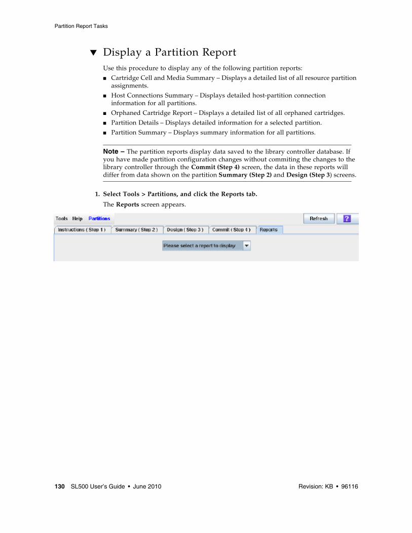
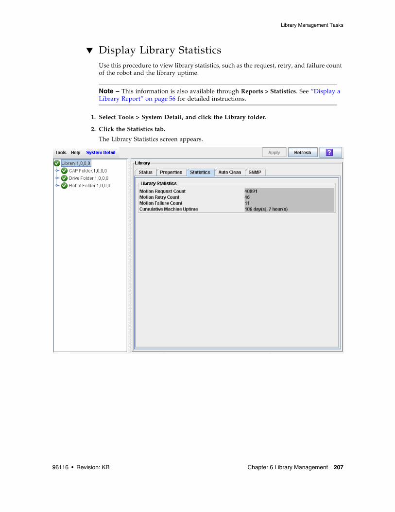
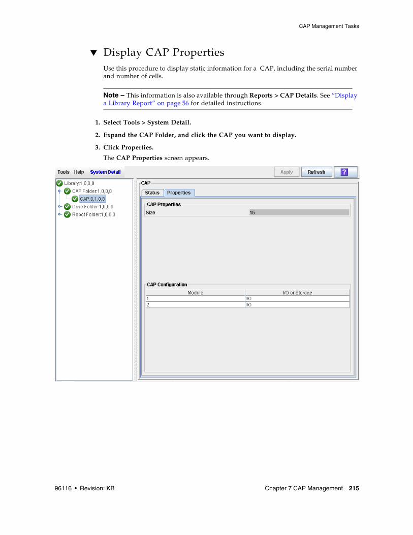
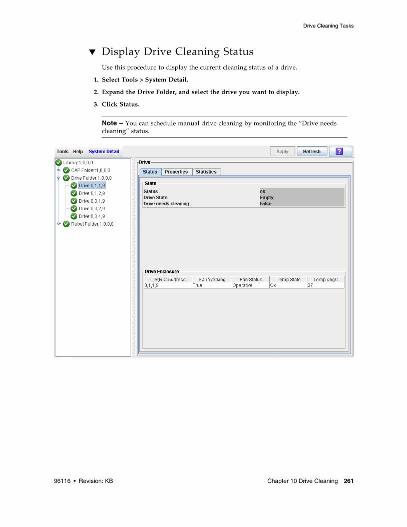
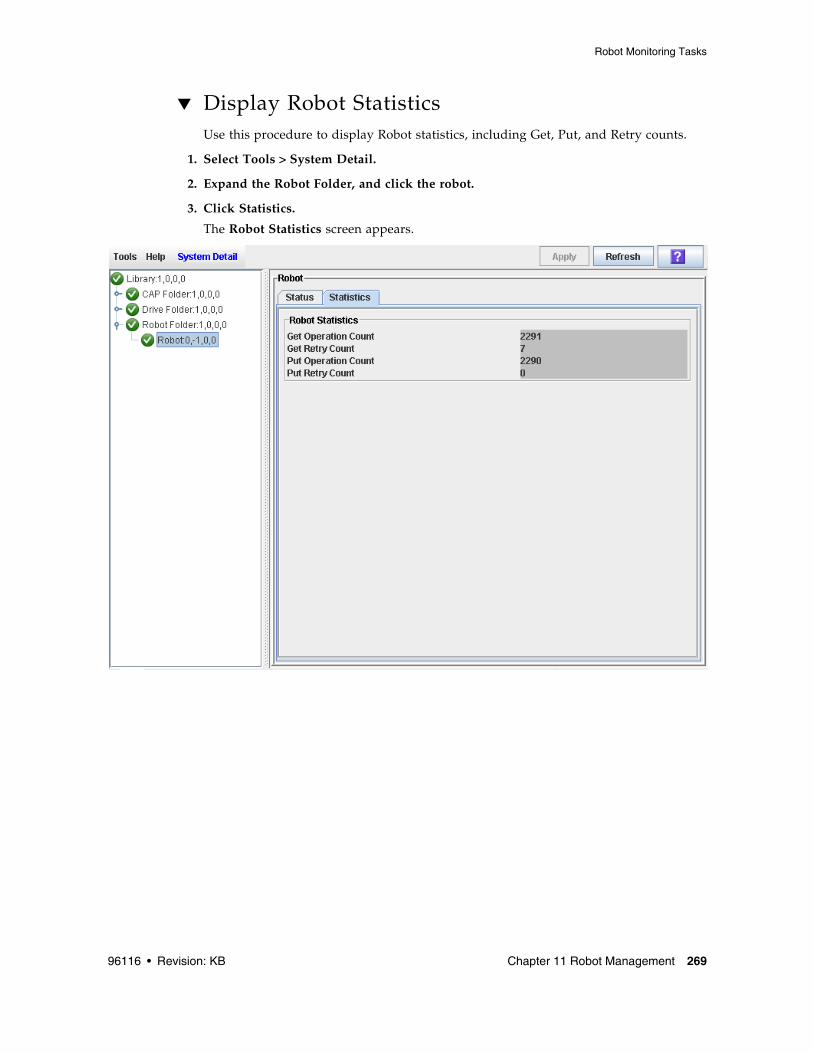
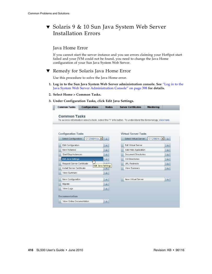
▼ Display a Library Report Use this procedure to display library reports available from the Tools > Reports menu.
Note – All report output is a static display of information sent from the library controller at the time the report is generated. The SL Console does not update the information dynamically unless you explicitly select the Update button on the Options Bar.
If you want to search the report data or save it to a file, see the following procedures:
■ “Search a Library Report” on page 58
■ “Save Library Report Data to a File” on page 60
Additional reports are available from the following menus:
■ Tools > Partitions
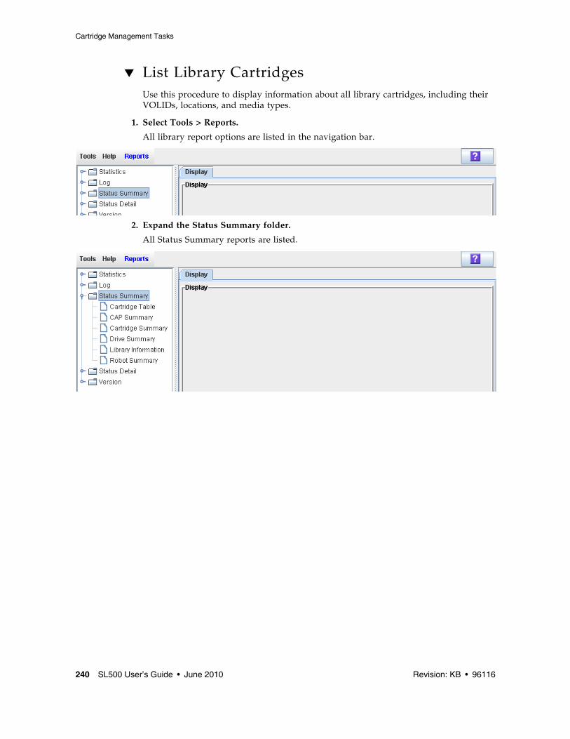
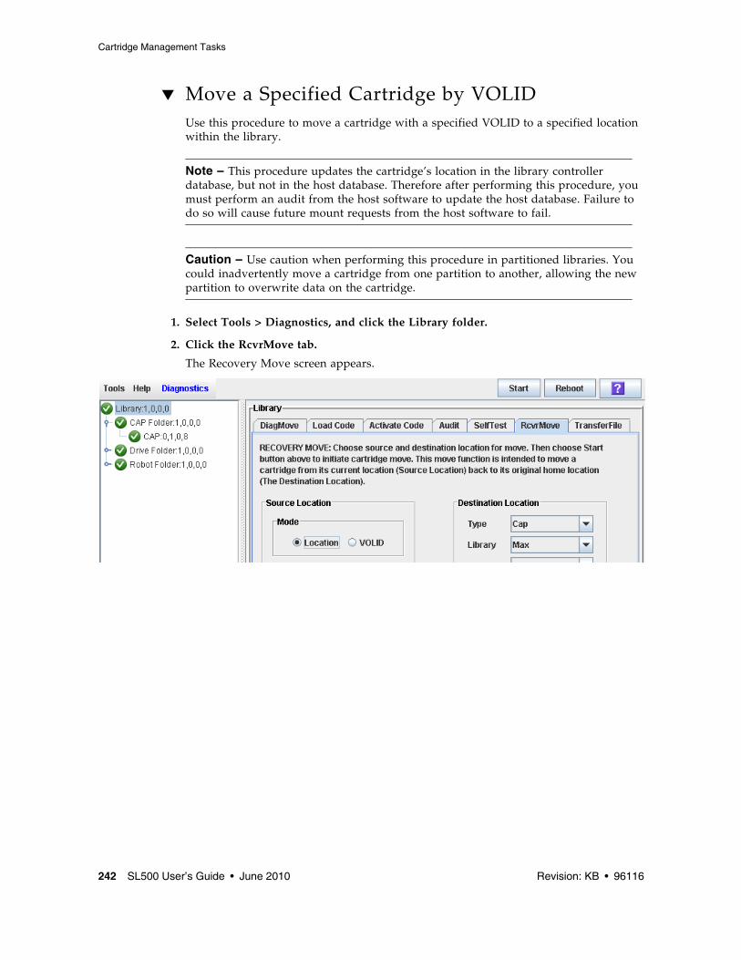
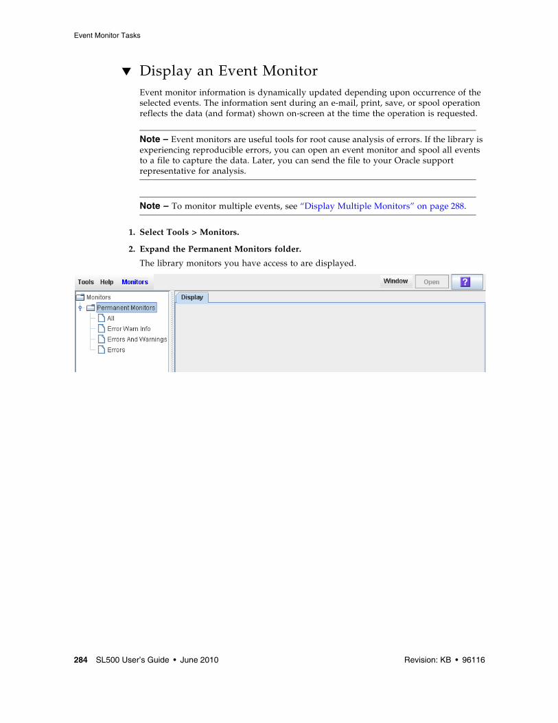
1. Select Tools > Reports.
The reports Display screen appears. All library report options are listed in the navigation bar.
2. In the navigation bar, expand a report category to see the report options.
▼ Search a Library Report Use this procedure to search a library report for a specified text string. This procedure can be performed on any of the library report screens.
1. Select Tools > Reports.
The reports Display screen appears. All library report options are listed in the navigation bar.
2. In the navigation bar, expand a report category to see the report options.
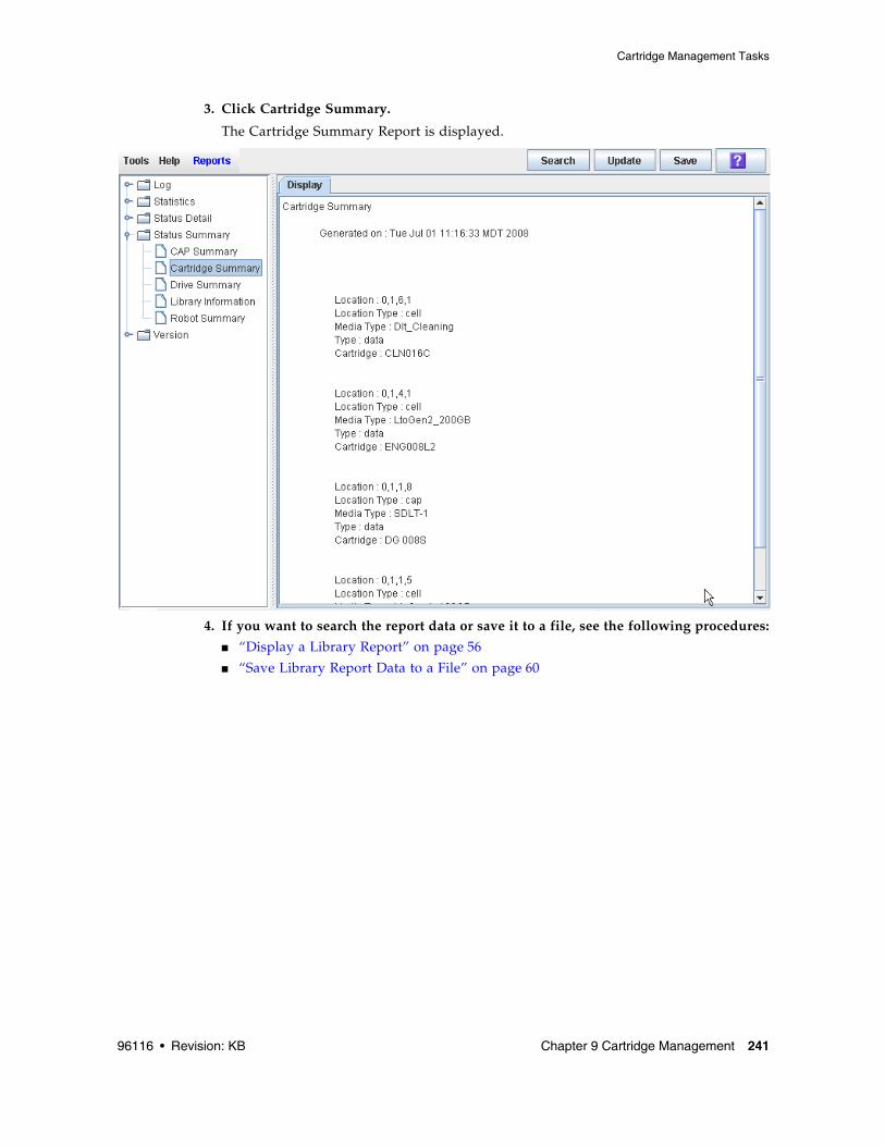
3. Click the report you want to display.
The specified report is displayed. All report screens include the Search button on the Options Bar.
4. Click Search.
The Search Text popup appears.
5. Enter the text string you want to search for, and click Search.
Note – The search is case-sensitive, and wildcards are not supported.
6. The Search Results popup appears, displaying the number of occurrences of the text string. All instances of the text string in the report are highlighted.
▼ Save Library Report Data to a FileUse this procedure to display a library report and save the data to a file. This procedure can be performed from any of the library report screens.
1. Once the file is saved, you can print it or include it in e-mail. This may be useful for communicating about library issues with your Oracle support representative. Select Tools > Reports.
The reports Display screen appears. All library report options are listed in the navigation bar.
2. In the navigation bar, expand a report category to see the report options.
3. Click the report you want to display.
The specified report is displayed. All report screens include the Save button on the Options Bar.
▼ Download the Standalone SL Console Installer Use this procedure to download the standalone SL Console installer program from the Oracle download site. and initiate it on your PC or workstation.
Note – Your Oracle CSE may have performed this procedure for you during library installation.
Note – You must have a valid login ID and password for the download site you are using. Contact your Oracle support representative for assistance.
1. Start a Web browser on your PC or workstation.
2. In the Address or Location Bar, enter the URL of the appropriate Oracle download site. See“Installation Requirements” on page 38 for details.
3. Log in to the Oracle download site using your assigned login ID and password.
4. Navigate to the standalone SL Console installer file.
5. Select the SL Console code level you want.
6. Select the appropriate installer file for your platform:
■ Microsoft Windows: SLConsole_Windows.exe
■ Oracle Sun Solaris: SLConsole_Solaris.bin
7. Save the file to your PC or workstation.
Note – To complete the installation, see “Install the Standalone SL Console” on page 64.
▼ Install the Standalone SL Console Use this procedure to install the standalone SL Console on your PC or workstation.
Note – Your Oracle CSE may have performed this procedure for you during library installation.
Note – Prior to using this procedure, you must have downloaded the standalone SL Console installer program. See “Download the Standalone SL Console Installer” on page 63.
1. Double-click the SL Console installer file icon on your PC or workstation to start the installation.
A digital signature warning popup appears.
2. Verify the name of the file and click Run.
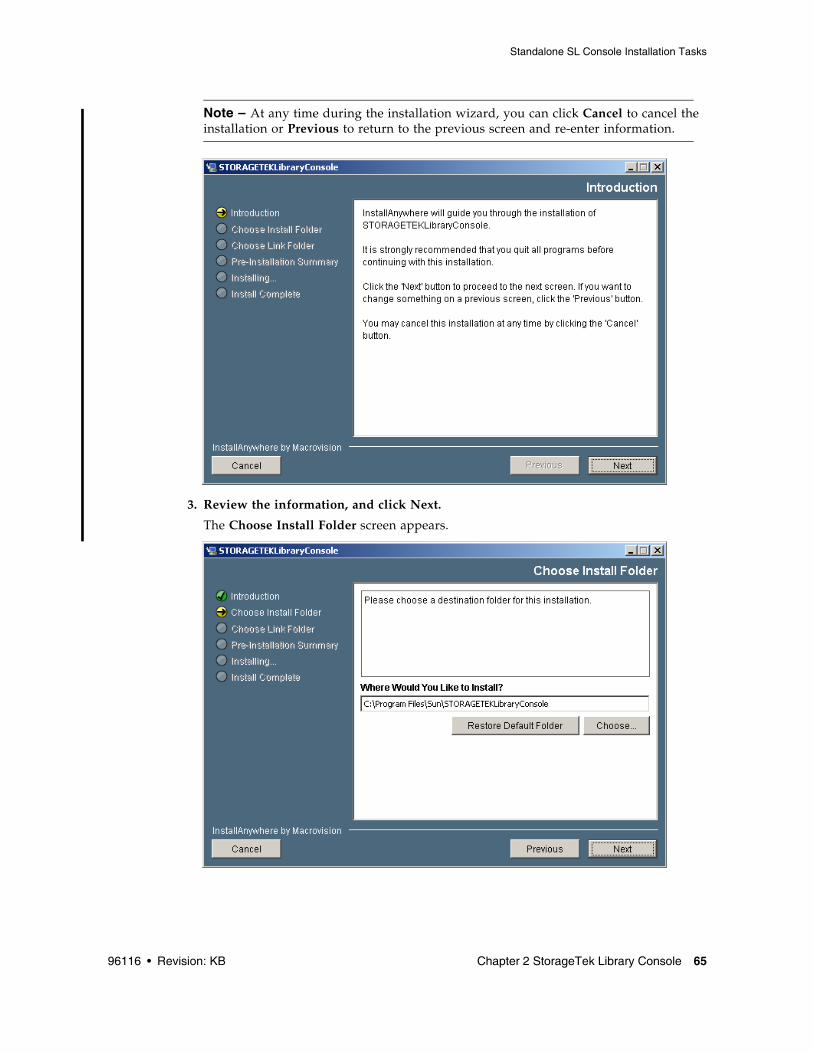
The installation wizard begins and the Introduction screen appears.
Note – At any time during the installation wizard, you can click Cancel to cancel the installation or Previous to return to the previous screen and re-enter information.
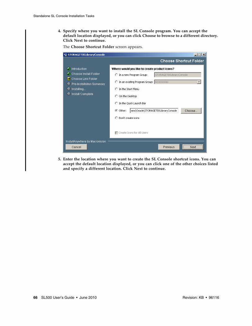
4. Specify where you want to install the SL Console program. You can accept the default location displayed, or you can click Choose to browse to a different directory. Click Next to continue.
The Choose Shortcut Folder screen appears.
5. Enter the location where you want to create the SL Console shortcut icons. You can accept the default location displayed, or you can click one of the other choices listed and specify a different location. Click Next to continue.
Note – On Solaris, the default location for shortcuts is the user’s home directory. However, shortcuts cannot be created in /, which is the root user’s home, so if you are installing on a Solaris platform as root you must choose something other than the default location. In this case, it is recommended that you choose /usr/bin or a similar location.
6. Review the information and verify that it is all correct. Click Install to continue.
The installation begins, and the Installing SL Console screen appears.
7. When the installation finishes, the Install Complete screen appears.
8. Review the information and click Done to exit the installation program.
96116 • Revision: KB 69
CHAPTER
3
Hardware Activation Files
The hardware activation utility allows you to activate selected optional features on the SL500 library.
Note – The hardware activation utility is available starting with SL500 firmware version 1300 and SL Console version FRS_4.00.
Hardware Activation FileA hardware activation file can be delivered to you in the following ways:
■ Via e-mail from Oracle Corporation
■ Installed by your Oracle support representative
The hardware activation file is a digitally signed image (.img) file containing one or more activation keys for features you have purchased. In order to ensure that features are activated on the correct library, the hardware activation file includes the serial number of the target library and can only be installed on that library.
Each hardware activation file is assigned a unique sequence number. The sequence number ensures that only one instance of a hardware activation file can be installed on a library at a time.
SL500 hardware activations are cumulative. When you install a new hardware activation file, the included features are added to the features already activated on the library.
Hardware Activation File Tasks This section provides detailed instructions for all tasks involved in installing and managing hardware activation files for library features.
Hardware Activation File Installation ProcessFollowing is a summary of the hardware activation file installation process. Optionally, you can choose to have this process done by your Oracle support representative.
1. You purchase one or more features for a specific Oracle StorageTek library from Oracle Corporation
2. Oracle sends you an e-mail with an attached hardware activation file.
3. You download the hardware activation file to a system accessible to the SL Console session.
4. You use the SL Console to verify and install the hardware activation file on the target library.
5. You reboot the library in order to activate the new features.
6. See the following topics for detailed information about implementing specific activated features:
▼ Receive a New Hardware Activation FileUse this procedure to receive a hardware activation file, which activates features for a specific StorageTek library.
Note – This procedure is not performed at the SL Console.
1. Purchase one or more features from Oracle Corporation
See your Oracle support representative for assistance.
2. Receive the hardware activation file from Oracle, via e-mail.
Following is a sample of the e-mail header: Subject: SL500 Hardware Activation Key CR6636975 Date: Wed, 23 Apr 2008 19:24:41 -0700 (MST) From: [email protected]
3. Download the hardware activation file to a system accessible to the SL Console session.
Use the standard method for saving e-mail attachments.
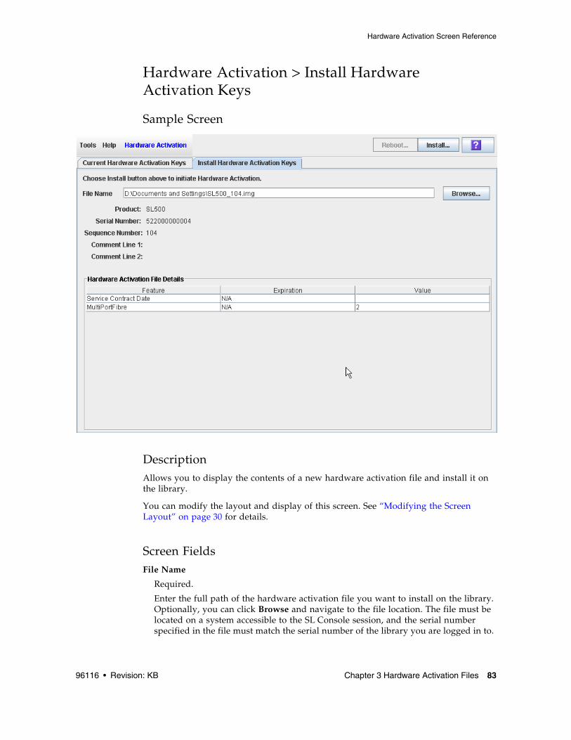
▼ Install a New Hardware Activation File on the Target LibraryUse this procedure to install a new hardware activation file on the target library.
Prior to performing this procedure, you must download a new hardware activation file to a system accessible to the SL Console session. See “Receive a New Hardware Activation File” on page 72.
1. Use the SL Console to log in to the target library.
See “General SL Console Usage Tasks” on page 41 for details.
2. Select Tools > Hardware Activation, and click the Install Hardware Activation Keys tab.
The Install Hardware Activation Keys screen appears.
3. In the File Name field, enter the full path of the hardware activation file you want to install, and press Enter. Optionally, you can click Browse and navigate to the file location.
The Hardware Activation File details appear in the lower part of the screen.
Note – If the library serial number in the specified hardware activation file does not match the serial number of the library you are logged in to, a warning appears and the hardware activation file detail is not displayed.
4. Review the hardware activation file details, and then click Install in the Options Bar.
The Activation File Installation Confirmation popup appears.
5. Click Yes to begin installing the activation file on the target library.
6. The library controller verifies the hardware activation file and proceeds as follows:
■ If there are no problems, the features included in the file are activated and the following popup appears.
■ A confirmation popup appears.
7. Click OK to dismiss the popup.
8. You must reboot the library in order for the new activation file features to be activated. Click the Reboot button in the Options Bar. See “Reboot the Library” on page 296 for detailed instructions.
9. You can verify that the activation file has been installed and activated successfully by displaying the current activation files. See “Display Current Hardware Activation Files” on page 75 for details.
10.Depending on the features included in the hardware activation file, you may need to perform additional tasks in order to use the new features.
■ See “Increasing Activated Capacity” on page 91 for special considerations that apply when you install a hardware activation file that adds activated capacity to the library.
■ See “Installing the Partitioning Feature” on page 95 for special considerations that apply when you install a hardware activation file with the Partitioning feature.
▼ Display Current Hardware Activation Files Use this procedure to display the features currently activated on the library you are logged in to.
1. Select Tools > Hardware Activation, and click the Current Hardware Activation Keys tab.
The Current Activation Keys screen appears, listing the currently activated features. See “Hardware Activation > Current Hardware Activation Keys” on page 80 for detailed information about the screen fields.
Note – If a feature has been installed, but the library has not yet been rebooted, the Enabled column will indicate “No”. The library must be rebooted in order for the feature to be activated.
▼ Delete a Hardware Activation File Use this procedure to delete a hardware activation file from an SL500 library.
You may need to delete a hardware activation file if there is an error in an installed file. Oracle will issue a new hardware activation file with the same sequence number as the original, and you must delete the original hardware activation file before installing the new one.
Caution – Deleting a hardware activation file is an exceptional situation. Be sure it is really what you want to do before you begin this procedure. Having extra hardware activation files installed on a library does not present any problems (for example, Capacity activation files that exceed the physical capacity of the library); the extra activation files are simply not used.
Caution – Deleting a Capacity hardware activation file reduces the activated capacity of the affected library module. This can result in orphaned cartridges and data that could be lost. See “Decreasing Activated Capacity” on page 91 and “Orphaned Cartridges in Non-Partitioned Libraries” on page 90 for details.
Caution – Deleting a Partitioning hardware activation file deletes the Partitioning feature from the library. See “Deleting the Partitioning Feature” on page 98 for details about the effects on the library configuration.
1. Use the SL Console to log in to the target library.
See “General SL Console Usage Tasks” on page 41 for details.
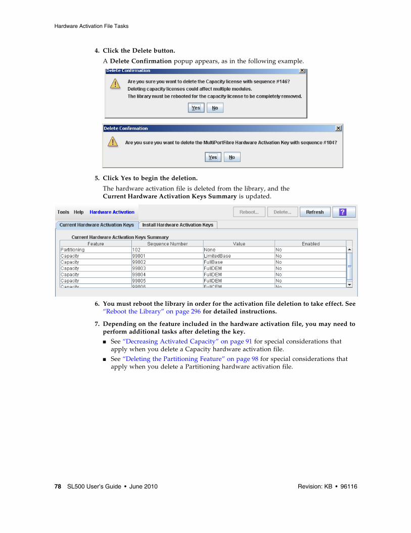
A Delete Confirmation popup appears, as in the following example.
5. Click Yes to begin the deletion.
The hardware activation file is deleted from the library, and the Current Hardware Activation Keys Summary is updated.
6. You must reboot the library in order for the activation file deletion to take effect. See “Reboot the Library” on page 296 for detailed instructions.
7. Depending on the feature included in the hardware activation file, you may need to perform additional tasks after deleting the key.
■ See “Decreasing Activated Capacity” on page 91 for special considerations that apply when you delete a Capacity hardware activation file.
■ See “Deleting the Partitioning Feature” on page 98 for special considerations that apply when you delete a Partitioning hardware activation file.
Hardware Activation Screen ReferenceThis section includes detailed descriptions of all SL Console hardware activation file screens, arranged by screen navigation path. For example, Activation File Management > Install Activation File indicates the screen accessed by clicking Tools and then Hardware Activation from the Menu Bar, and then clicking the Install Activation File tab.
Screen
Hardware Activation > Current Hardware Activation Keys 80
Unique sequence number assigned to the hardware activation file by Oracle Corporation
Note – Sequence numbers 99000 and above are permanently retained and cannot be deleted from the library.
Value
Display only.
Qualification for the feature, if applicable. For example, for the Capacity feature, this field displays the capacity the activation file provides, such as “FullBase”, “ThirdDEM”, etc. Depending on the feature, the field may be blank or indicate “None”.
Enabled
Display only.
Indicates whether the feature is currently activated on the library. Options are:
■ Yes – Feature has been activated
■ No – Feature has been installed, but not activated; the library must be rebooted in order for the feature to be activated.
Associated Module Capacity Activation Detail
Module Number
Display only.
Numeric module ID. Possible values are 1–5.
Capacity
Display only.
Total module capacity that has been activated for use. Possible values are:
■ Full Capacity – All storage cells in the module are activated for use.
■ None – No storage cells in the module have been activated for use. May also indicate that the module is not installed in the library.
■ 1/3 Capacity – One-third of the storage cells in the module have been activated. Applies only to the DEM.
■ 2/3 Capacity – Two-thirds of the storage cells in the module have been activated. Applies only to the DEM.
Sequence Number
Display only.
Hardware activation file sequence numbers used in providing the indicated capacity. If more than one hardware activation file is involved, the sequence numbers are separated by commas.
000 indicates no hardware activation file has been installed for the module.
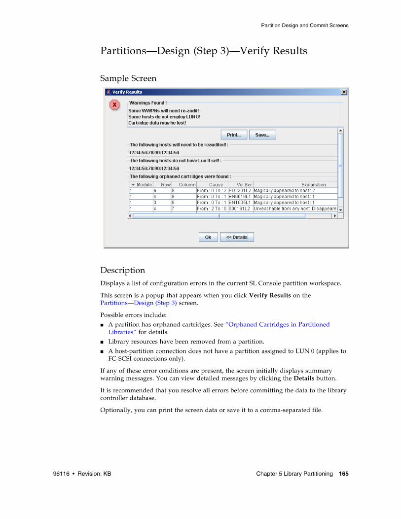
DescriptionAllows you to display the contents of a new hardware activation file and install it on the library.
You can modify the layout and display of this screen. See “Modifying the Screen Layout” on page 30 for details.
Screen FieldsFile Name
Required.
Enter the full path of the hardware activation file you want to install on the library. Optionally, you can click Browse and navigate to the file location. The file must be located on a system accessible to the SL Console session, and the serial number specified in the file must match the serial number of the library you are logged in to.
Type of library the hardware activation file is for. For example, SL3000 or SL500.
Serial Number
Display only.
Serial number of the library the hardware activation file is for. This entry must match the serial number of the library you are logged in to in order for the hardware activation file to be valid for this library.
Sequence #
Display only.
Unique sequence number assigned to the hardware activation file by Oracle Corporation
Note – Sequence numbers 99000 and above are permanently retained and cannot be deleted from the library.
Comment Line 1
Display only.
Optional comment concerning the hardware activation file, from Oracle Corporation
Comment Line 2
Display only.
Optional comment concerning the hardware activation file, from Oracle Corporation
Activation File File Details
Feature
Display only.
Name of a feature included in the hardware activation file.
Expiration
Display only.
Number of days until the feature is due to expire. Because SL500 library features do not expire, the value for this field is always “N/A”.
Value
Display only.
Qualification for the feature, if applicable. For example, for the Capacity feature, this field displays the total amount of storage capacity the activation file provides. Depending on the feature, the field may be blank.
ButtonsInstall
Click to install the displayed hardware activation file on the library you are logged in to.
Click to navigate to the hardware activation file you want to display and install.
Note – If the library serial number in the specified hardware activation file does not match the serial number of the library you are logged in to, a warning appears and the hardware activation file detail is not displayed.
? (Help)
Click to display online help for the screen.
See Also ■ Hardware Activation > Current Hardware Activation Keys
The SL500 library includes the Capacity on Demand feature. Capacity on Demand separates physical capacity from activated capacity, and allows you to pay only for the capacity you need. Then as your needs grow, you can add modules and activate the portion that you need. To expand capacity within a module, you need only purchase and install a hardware activation file for the new capacity, and then reboot the library.
Note – Starting with SL500 firmware version 1300 and SL Console version FRS_4.00, storage capacity upgrades must be installed through the SL500 hardware activation utility. See “Hardware Activation Files” for details.
Note – This feature controls cartridge storage cells only. All installed tape drives are available by default. All cells in CAPs configured for enter and eject operations are available if the module containing the CAP has any activated storage cells
Capacity on Demand Features and RestrictionsThis section describes important features and restrictions of Capacity on Demand that will help you to plan for and use the feature in your SL500 library.
■ Only activated storage cells can be used for tape cartridge storage. Unactivated storage cells cannot be used for cartridge storage, nor can they be accessed by any hosts.
■ The minimum activated capacity is 30 storage cells for LTO-only libraries, and 24 storage cells for mixed-media libraries. This is identified as a LimitedBase activation key.
■ You can purchase additional activated capacity in the following increments:
■ FullBase—Activates all storage cells in the Base Module.
■ FullDEM—Activates all storage cells in a Drive Expansion Module (DEM).
■ ThirdDEM—Activates one-third of the storage cells in a DEM. To activate two-thirds of a DEM, you would install two ThirdDEM hardware activation files. To activate all of a DEM, you could install three ThirdDEM hardware activation files or one FullDEM activation file.
■ FullCEM—Activates all storage cells in a Cartridge Expansion Module (CEM).
■ After installing additional activated capacity, you need to reboot the library. Once verified by the library controller, the additional storage cells are available for use.
■ Storage capacity is incremental. Total activated capacity is equal to the sum of the capacities specified in each hardware activation file installed and activated on the library.
■ The order that capacity activation files are installed is not significant (that is, it does not need to match the order of the modules in the SL500 frame).
TerminologyThe following terms are used to describe library capacity management:
■ Physical or installed capacity—The number of storage cells physically present in the library.
■ Activated capacity—The number of storage cells the library is activated to use. This cannot exceed the installed capacity.
Planning Library CapacityThe SL500 does not support gaps in activated capacity; all storage cells must be contiguous. This has the following effects on capacity planning.
You can begin adding activated capacity to a module only if the module directly above it is activated at full capacity.
Deleting a Capacity activate for a module in the middle of a library will cause the modules below it to be unavailable.
Note – CEMs must be at the bottom of any SL500 configuration. A CEM cannot be installed between a Base Module and a DEM.
Example: Base Module + DEM
The Base Module must be activated at full capacity before you can begin adding activated capacity to the DEM.
Example: Base Module + DEM + CEM + CEM
Removing any portion of the DEM capacity will make both CEMs unavailable.
Capacity on Demand Features and Restrictions
96116 • Revision: KB Chapter 4 Capacity on Demand 89
LTO Activated Capacity by Module
Mixed Media Activated Capacity by Module
Module
Hardware Activation Key Value
Module Activated Capacity *
Library Total Count
Base Module
Shipped standard LimitedBase 30
As last module FullBase 50
With any module underneath FullBase 66
Drive Expansion Module (DEM)
As last module ThirdDEM (increments of
26, 26, 25)
77
With any module underneath ThirdDEM (increments of
28, 28, 28)
84
Cartridge Expansion Module (CEM) after Base Module or DEM
As last module FullCEM 104
With any module underneath FullCEM 114
Cartridge Expansion Module (CEM) after CEM
As last module FullCEM 110
With any module underneath FullCEM 120
* All capacities assume no reserved cells and all CAPs are configured for enter and eject op-erations.
Module
Hardware Activation Key Value
Module Activated Capacity *
Library Total Count
Base Module
Shipped standard LimitedBase 24
As last module FullBase 42
With any module underneath FullBase 56
Drive Expansion Module (DEM)
As last module ThirdDEM (increments of
21, 21, 21)
63
With any module underneath ThirdDEM (increments of
Cell Assignment RulesThe library controller uses the following rules when filling activated storage cells with cartridges:
■ All cells in column 1 are filled first, then the cells in column 2, then 3, and so on.
■ Cells within each column are filled from top to bottom, starting with the first row after any reserved cells. For example, if the top three cells in a column are reserved, cell assignment within the column starts with row 4.
■ Once all cells within a module are filled, cell assignment moves to the next module, using the same top-to-bottom, column by column approach.
In partitioned libraries, the library controller applies these rules separately to each partition.
Orphaned Cartridges in Non-Partitioned Libraries
Note – For a discussion of orphaned cartridges in partitioned libraries, see “Orphaned Cartridges in Partitioned Libraries” on page 100.
In non-partitioned libraries, an orphaned cartridge is a cartridge located in an unactivated storage cell. Orphaned cartridges are inaccessible to all hosts.
A cartridge can become orphaned for a variety of reasons. Following are some possible causes:
■ Activated storage capacity has been reduced.
■ The cartridge has been moved to an unactivated or inaccessible cell through manual intervention.
Cartridge Expansion Module (CEM) after Base Module or DEM
As last module FullCEM 84
With any module underneath FullCEM 94
Cartridge Expansion Module (CEM) after CEM
As last module FullCEM 90
With any module underneath FullCEM 100
* All capacities assume no reserved cells and all CAPs are configured for enter and eject op-erations.
Module
Hardware Activation Key Value
Module Activated Capacity *
Library Total Count
Implementing Changes to Activated Capacity
96116 • Revision: KB Chapter 4 Capacity on Demand 91
Implementing Changes to Activated Capacity
Increasing Activated CapacityFollowing are special considerations for installing new activated storage capacity.
■ See “Hardware Activation File Installation Process” on page 70 for details on purchasing and installing a Capacity activation file.
■ If the new activated capacity exceeds the physical capacity, no corrective action is necessary. Physical cells that cannot be activated due to capacity limits will be activated later whenever additional capacity activation files are installed.
■ You must configure all affected library host applications to recognize the new activated storage cells. See “Host Notification of Capacity Changes” on page 92 for details.
■ In non-partitioned libraries, all newly activated cells are immediately available for use.
■ In partitioned libraries, all newly activated cells are added as “unallocated,” and are therefore not available for use. You must manually allocate the new cells to partitions before the cells can be used for cartridge storage. See “Partition Configuration Tasks” on page 107 for detailed instructions.
Decreasing Activated CapacityFollowing are special considerations for deleting activated storage capacity.
Caution – Deleting activated capacity is an exceptional situation; use caution when doing so.
■ See “Delete a Hardware Activation File” on page 76 for details on deleting activated capacity.
■ Storage cells corresponding to the reduced capacity will become inaccessible, and any cartridges within those cells will be orphaned. No checks are made to identify cartridges that will be orphaned. See “Orphaned Cartridges in Non-Partitioned Libraries” on page 90 for details.
■ You must configure all affected library host applications to recognize the activated storage cell changes. See “Host Notification of Capacity Changes” on page 92 for details.
■ For partitioned libraries:
■ The total number of storage cells allocated to all library partitions cannot exceed the activated capacity of the library.
Caution – You must manually de-allocate cells from partitions so the total allocation does not exceed the new activated capacity.
■ If, after capacity has been decreased, the total number of cells allocated to all partitions is still less than the new activated capacity, you do not need to reconfigure the partitions.
Host Notification of Capacity Changes When storage capacity is added or removed, the library controller notifies all affected hosts according to their interface requirements. SCSI hosts are notified by a “Mode Parameters Changed” unit attention. The host must re-audit the library to determine the specific configuration changes. See the appropriate tape management software documentation for detailed procedures and commands.
96116 • Revision: KB 93
CHAPTER
5
Library Partitioning
Note – Starting with SL500 firmware version 1300 and SL Console version FRS_4.00, library partitioning upgrades must be installed through the SL500 hardware activation utility. Partitioning established on a library prior to version 1300 is retained permanently. See “Hardware Activation Files” for details.
Library partitioning allows sections of the SL500 library to be assigned for exclusive use by specified hosts. For example, you can configure one group of storage cells and drives to be used only for Veritas operations, and another group only for Tivoli operations. This allows you to configure an SL500 library for applications running on multiple hosts and operating systems.
Partitioning Features and RestrictionsThis section describes important features and restrictions of library partitioning that will help you to configure and use partitioning in your SL500 library.
■ You can configure up to eight partitions within an SL500 library.
■ A partition can be as small as a single storage cell, CAP cell, or tape drive. Cells and drives within a partition do not need to be adjacent.
■ Storage cells and tape drives allocated to a partition can be used only by the hosts assigned to that partition. Hosts assigned to other partitions cannot access the contents of these cells and drives. See “Storage Cells and Drives” on page 100 for details.
■ Storage cells and drives not allocated to any partition cannot be accessed by any hosts. For example, you might leave an area of cells unallocated, in preparation for future partitioning.
■ CAP cells can be allocated for exclusive use by a partition, or they can be left unallocated for common use by all hosts. See “Partitions and CAPs” on page 102 for details.
Note – Starting with SL500 firmware version 1300 and SL Console version FRS_4.00, library partitioning upgrades must be installed through the SL500 hardware activation utility. Partitioning established on a library prior to version 1300 is retained permanently. See “Hardware Activation Files” for details.
Note – ACSLS does not support partitioning on the SL500 library.
Enabling and Disabling PartitioningIn order for you to use partitions in a library, the partitioning feature must be enabled by your Oracle CSE. Contact your Oracle CSE for assistance.
A library with partitioning enabled can be in either of the following states:
■ Partitioned – The library has at least one user-defined partition with a valid partition ID.
■ Non-partitioned – The library has no user-defined partitions. A non-partitioned library behaves in the same manner as a library that does not have partitioning enabled; that is all storage cells, drives, and CAPs are accessible to all hosts.
To disable partitioning on a library, you must first delete all partitions. The library state will then change to “non-partitioned.”
Partition PlanningThe partitioning feature offers great flexibility in the use of your library. It also requires careful planning, a thorough knowledge of library wall and storage cell mapping, and expertise in configuring and administering host software applications. There must be clear communication among all parties involved, including system programmers and administrators, library operators, and your Oracle service representative.
Before creating partitions, you must plan the storage area that is needed for resident tape cartridges and anticipate the number of required free cells. You must understand the boundaries of each partition and the host ownership relationships. You must verify that all tape drives and cartridges have been moved to the proper locations, according to the plannedhost/storage cell and host/tape drive assignments.
Installing the Partitioning FeatureThe following special considerations apply after you successfully install the Partitioning feature on a previously non-partitioned library.
■ You must reboot the library after installing the Partitioning activation file.
■ Until you create at least one partition, the library remains in a non-partitioned state; that is all activated storage cells, drives, and CAPs are accessible to all hosts.
Allocated Storage CapacityIn partitioned libraries, the total number of storage cells allocated to all library partitions cannot exceed the activated capacity of the library.
In partitioned libraries, there is no default active storage region. You must explicitly assign storage cells to partitions, thereby configuring the active storage regions for each partition. See “Partitioning Process” on page 104 for details.
Partition ConfigurationsTo configure a partition, you must define the following information:
■ Partition Summary Information
■ Host-Partition Connections
■ Partition Boundaries
For detailed instructions on defining library partitions, see “Partitioning Process” on page 104.
Partition Summary InformationPartition summary information includes the partition ID and name, and the barcode format to be used on cartridge labels. Partition IDs must be unique and can range from 1–8.
Host-Partition ConnectionsHost-partition connections identify the hosts that are able to access a partition. Each partition appears to the host as a separate library module. A host can control one or more partitions. In addition, it is possible for more than one host to control a single SCSI partition, but it is recommended that you exercise caution in implementing this configuration, as some host applications may not allow for resource sharing.
A partition can have one or more host-partition connections. The host-partition connection configuration is user-defined and consists of the following information:
■ World Wide Port Name of the host bus adapter
■ Port number of the library Fibre Channel card
■ Logical unit number (LUN) of the partition on the host
See “Configure a Host-Partition Connection” on page 111 for detailed instructions on defining this information.
Partition BoundariesPartition boundaries identify the storage cells, drives, and CAP cells that are part of each partition. Only unallocated cells can be added to a partition, and only allocated cells can be removed.
You can define partition boundaries in any of the following ways:
■ Select individual cells or rectangular groups of cells to add or remove from a partition. Cells or cell groups do not have to be contiguous.
■ Select an entire module side to add or remove from a partition. Sides do not have to be contiguous.
■ Select an entire module to add or remove from a partition. Modules do not have to be contiguous.
Sample Partition Configuration
FIGURE 5-1 on page 97 shows a sample SL500 library partition configuration. In this example, there are three defined partitions:
The screen display is from the perspective of Partition 1, therefore the resources allocated to Partition 1 are shown in gold, and the resources allocated to Partition 2 and Partition 6 are shown in red. TABLE 5-1 on page 97 describes the resource allocation in detail.
TABLE 5-1 Partition Example – Resource Description
Resource Group Included Resources
Partition 1 All resources are shown in gold. Includes the following:■ Tape drive in the Base Module■ Storage cells in the left side of the Base Module■ Top two CAP cells in the Base Module
Partition 2 All resources are shown in red. Includes the following:■ Top tape drive in the Drive Module■ Storage cells in the right side of the Base Module■ No allocated CAP cells
Partition 6 All resources are shown in red. Includes the following:■ Bottom tape drive in the Drive Module■ Storage cells in the Drive Module■ Bottom two CAP cells in the Base Module
Deleting the Partitioning FeatureYou can delete the Partitioning feature by deleting the Partitioning hardware activation file from the library. See “Delete a Hardware Activation File” on page 76 for detailed instructions. You must reboot the library after deleting the Partitioning activation file in order for the deletion to take effect.
Note – Deleting the Partitioning feature is an exceptional situation; be sure this is what you really want to do.
Deleting the Partitioning feature has the following effects on the library configuration:
■ Changes the library state to “non-partitioned.”
■ Makes all activated storage cells, drives, and CAPs accessible to all hosts.
■ All existing partition summary information and resource allocations are retained, but not usable. If the Partitioning activation file is later re-installed, the partition allocations are restored.
Partitions and Library Resources
Library Resource Addresses Resource addresses uniquely identify each resource (storage cells, drives, and CAP cells) within the library. The SL500 library and attached hosts use the following addressing schemes:
■ Library Internal Address
■ Host SCSI Element Address
Each partition appears to a host as a separate library; this is reflected in the partition address.
Common CAP cell Middle CAP cell in the Base Module
Unassigned All resources shown in white
Not Accessible All resources shown x’ed out
Orphaned cartridge
Cartridge in unallocated (white) storage cell in the Base Module
TABLE 5-1 Partition Example – Resource Description
Library Internal AddressThe library internal address is used by the SL500 library controller and the SL Console device tree to identify the physical location of each resource. The addressing scheme used by the SL500 is a four-digit, comma-separated value, specifying the library, module, row, and column, as viewed from inside the library, facing the drive bays. This addressing scheme is commonly referred to as the LMRC address.
The format of the SL500 LMRC address is l,m,r,c where:
■ l= library or partition number. In partitioned libraries, l is the partition ID (1–8). In non-partitioned libraries, l is always “0”.
■ m = module number (1–5). The Base Module is 1, additional drive expansion and storage expansion modules are 2–5.
■ r = row number. Numbered consecutively from the top, down, with row 1 at the top.
■ c = column number, as follows:
■ Base module, left side of library = 1–4
■ Base module, right side of library = 5–8
■ DEM (Drive Expansion Module) drive column, rear of library = 9
■ CEM (Cartridge Expansion Module) columns, rear of library = 9–11
Internal Address Examples■ If the entire Base Module is allocated to Partition 1, the internal address for a
cartridge in row 8, column 1 in the Base Module is: 1, 1, 8, 1.
■ If the entire CEM is allocated to Partition 2, the internal address for a cartridge in row 10, column 1 is: 2, 2, 10, 1.
Host SCSI Element AddressThe element address is used by hosts to uniquely identify each library resource available to the host.
SCSI element numbering uses a single integer to identify each library resource. SCSI element numbering within partitioned libraries is continuous for each partition, even if cell locations for the partition are not adjacent. SCSI element addresses for a partition start at the lowest module, row, and column within the partition, then proceed by row until the end of the column, then increment by column until the end of the module.
When additional resources are allocated to an existing SCSI partition, the original resources are not renumbered. This helps to minimize disruption to the SCSI host.
SCSI Element Address Examples
If a library’s base and storage expansion modules are allocated to Partition 1 and the drive module is allocated to Partition 2, SCSI element numbering is as follows:
■ Numbering for Partition 1 begins at the first available storage cell in the Base Module and continues through the last available cell in the storage module cell.
■ Numbering for Partition 2 begins with the first available storage cell in the drive module PRC Address and ends with the last available cell in that module.
Storage Cells and Drives All storage cells, tape drives, and cartridges allocated to a partition are owned exclusively by the assigned host and cannot be accessed by other hosts. For example, if a group of tape drives is allocated to a partition, only the host assigned to that partition can use those drives.
Storage cells and drives that are not allocated to any partition cannot be accessed at all. For example, you can leave an area of cells unallocated in preparation for a planned future partition.
On the SL Console screens and reports, storage cells and drives appear in any of the following states:
■ Allocated – Assigned to the current partition.
■ Unallocated (or Unassigned) – Not assigned to any partition; available to be assigned to any current partition.
■ Unavailable – Assigned to another partition.
■ Not accessible – Not available for host operations; for example, cells reserved for diagnostic cartridges, cells that are physically blocked.
Note – Robots are shared resources and cannot be allocated exclusively to a partition.
To display partition assignments for storage cells and drives, see “Partitions—Reports—Cartridge Cell and Media Summary” on page 176.
Orphaned Cartridges in Partitioned Libraries
Note – For a discussion of orphaned cartridges in non-partitioned libraries, see “Orphaned Cartridges in Non-Partitioned Libraries” on page 110.
In partitioned libraries, an orphaned cartridge is a cartridge located in an unallocated cell or drive (that is, a cell or drive not allocated to any defined partition).
Caution – If a host encounters an orphaned cartridge it might treat the cartridge as scratch and overwrite the data. Therefore, it is very important to disposition orphaned cartridges properly.
A cartridge can become orphaned for a variety of reasons. Following are some possible causes:
■ Partition boundaries have changed.
■ A partition has been deleted.
■ The cartridge has been moved to an unallocated or inaccessible cell through manual intervention.
If the SL Console identifies an orphaned cartridge, it displays a warning message. You can then use the following tools to help you resolve and disposition the orphaned cartridge:
Partitions and CAPsThe cells within each CAP can be allocated or unallocated individually to partitions. This allows for the following possible CAP configurations:
■ Common CAP
■ Split CAP
Note – Split CAPs are available to the SL500 only.
Common CAPIn a common, or unassigned, CAP, all cells in the CAP are left unallocated and can be used by any partition that does not have any CAP cells allocated to it. CAP cells are common by default – any CAP cells that are not explicitly allocated to a partition are treated as common.
A common CAP is a shared library resource. Each host must select a common CAP to use it and must release the CAP when done, to make it available to other hosts. No other host can access the CAP until the first host has completed the operation and released the CAP. For additional details, see “CAP Operations” on page 102.
Split CAPIn a split CAP, the cells in the CAP are allocated to one or more partitions. Each individual CAP cell can be allocated to one partition only. Cells in a split CAP can be allocated in any of the following ways:
■ All cells can be allocated to one partition.
■ All cells can be distributed among multiple partitions. For example, in an eight-cell CAP, two cells could be allocated to Partition 1, one cell to Partition 2, and the remaining cells to Partition 3.
■ Some cells can be allocated to one partition and the remainder left unallocated, or common. For example, in an eight-cell CAP, five cells could be allocated to Partition 3, and the remaining cells left common.
When configuring a split CAP, you must plan carefully for anticipated CAP usage. A partition with allocated CAP cells can use the cells allocated to it only. It cannot use CAP cells allocated to other partitions, nor can it use common CAP cells.
CAP Operations In a partitioned library, it is recommended that you assign partitions to the CAP Open button on the library control panel prior to pressing the button to open the CAPs.
Once you have assigned partitions to the CAP Open button, only CAPs containing cells that are accessible to those partitions will open. Depending on how your library’s CAPs are configured, this operation may expose CAP cells that are not accessible to the selected partitions. As a safeguard, however, CAPs that contain only inaccessible cells and CAPs with cartridges in inaccessible cells do not open.
For detailed instructions, see “Enter Cartridges Into a Partitioned Library” on page 135 and “Eject Cartridges From a Partitioned Library” on page 138.
Note – Starting with SL500 firmware version 1300 and SL Console version FRS_4.00, library partitioning upgrades must be installed through the SL500 hardware activation utility. Partitioning established on a library prior to version 1300 is retained permanently. See “Hardware Activation Files” for details.
Partition Configuration ProcessWhen configuring library partitions for the first time, it is recommended that you use the library partition screens in the following sequence:
1. Instructions (Step 1) – Review summary instructions for the partition configuration process.
2. Summary (Step 2) – Display summary partition configuration and host-partition connection information. Optionally access other screens to perform the following tasks:
■ Add Partition
■ Modify Partition
■ Delete Partition
■ Add Connection
■ Modify Connection
■ Delete Connection
3. Design (Step 3) – Display and optionally modify detailed partition boundary information. Optionally access other screens to perform the following tasks:
■ Verify Partition Configurations
■ Refresh the display with current data from the library controller database
4. Commit (Step 4) – Commit all changes made in the Summary(2) and Design (3) screens, and all associated popups, to the library controller database. Optionally access other screens to perform the following task:
■ Refresh the display with current data from the library controller database
You can use the Reports screen at any time to display, and optionally save or print, partition configuration information from the library controller database.
SL Console Partition WorkspaceThe partition Summary (Step 2) and Design (Step 3) screens, and all associated popups, give you a dynamic workspace to design your library partitions. All partition configuration information is automatically saved to the partition workspace in SL Console memory and retained for the duration of your SL Console session. This allows you to switch among partition views and leave and return to the partition screens any number of times without losing your configuration changes.
Information in the SL Console partition workspace is committed to the library controller database only through the Commit (Step 4) screen. The information is lost if any one of the following occurs before you have committed your updates:
■ You actively log off the SL Console session.
■ The SL Console session times out or the connection to the library is lost.
■ You actively refresh the SL Console workspace from the current library controller database. This is done through the Refresh button on the Summary (Step 2) and Design (Step 3) screens.
▼ Create a Partition Use this procedure to create a new library partition and assign its storage capacity. You can create up to eight partitions, with IDs from 1–8.
1. Select Tools > Partitions, and click the Summary (Step 2) tab.
The Summary (Step 2) screen appears.
2. lick Add Partition.
The Add Partition popup appears.
3. Select the Partition ID you want to add, and enter the Name, and Barcode Presentation.
Note – Partition IDs do not need to be contiguous. For example, you can create partition 2 and partition 4, with no partitions 1 or 3.
Your partition configuration changes are saved to the SL Console partition workspace for the duration of this login session.
To update the library controller database with all changes from this SL Console login session, see “Verify Partition Configurations” on page 114 and “Commit Partition Configuration Changes” on page 117.
▼ Configure a Host-Partition ConnectionUse this procedure to configure the connection between a host and a selected partition. You must perform this procedure in order for the partition to be accessible by the host.
Each partition can have up to nine host connections, each with a unique LUN. Also, each host can connect to multiple partitions.
Note – The SL500 supports only SCSI connections between the host and library.
1. Select Tools > Partitions, and click the Summary (Step 2) tab.
2. lick Add Connection.
Note – Each initiator connected to the library must have one library partition assigned to LUN 0. When you verify or commit partition configuration changes, the SL Console will notify you if an initiator does not meet this requirement.
▼ Design a PartitionUse this procedure to add or remove library resources (storage cells, tape drives, and CAP cells) from a partition.
Note – Library resources can be allocated to only one partition at a time. If you want to add resources to a partition but the resources are already allocated to another partition, you must first remove the resources from the assigned partition, and then add them to the new partition.
1. Select Tools > Partitions.
2. Click the Design (Step 3) tab.
The Design (Step 3) screen appears, displaying the current configuration of the library.
3. In the Partition pull-down menu, select the partition you want to configure.
All screen fields are updated to reflect the current configuration for the selected partition.
4. Choose the Select by method, and click either the Add or Remove radio button.
5. Use the library map to select the resources you want to add or remove.
Note – See “Partitions—Design (Step 3)” on page 160 for detailed instructions on using the library map.
Your partition configuration changes are saved to the SL Console partition workspace for the duration of this login session.
To update the library controller database with all changes from this SL Console login session, see “Verify Partition Configurations” on page 114 and “Commit Partition Configuration Changes” on page 117.
▼ Verify Partition Configurations Use this procedure to verify partition configuration changes you have made during this SL Console login session. This procedure warns you of the following possible errors:
■ A partition has orphaned cartridges. See “Orphaned Cartridges in Partitioned Libraries” on page 100 for details.
■ Library resources have been removed from a partition.
■ A host connected to the library does not have a partition assigned to LUN 0.
Note – This procedure verifies only one partition at a time. If you need to verify multiple partitions, you must repeat this procedure separately for each partition.
1. Select Tools > Partitions.
2. Click the Design (Step 3) tab.
The Design (Step 3) screen appears, displaying the current configuration of the library.
3. In the Partition pull-down menu, select the partition you want to verify.
All screen fields are updated to reflect the current configuration for the selected partition.
4. In the Options Bar, click Verify.
The boundaries of the selected partition are verified, including the locations of all tape cartridges.
Note – This verification is performed on the current partition configuration in the SL Console partition workspace only. It does not verify current partition boundaries against the library controller database; therefore it cannot identify configuration conflicts that may arise due to other users performing cartridge movements or library configuration changes—through the command line interface, other SL Console sessions, or host applications—at the same time you have made partition changes.
The Verify Results popup appears, indicating whether there are any orphaned cartridges or other errors in the current partition configuration.
5. To display detailed warning messages explaining the reasons for any orphaned cartridges, click Details.
You can use the Details button to toggle between the expanded and collapsed views of the warning messages.
6. Optionally, in the expanded view of the warning messages you can do the following:
■ Click Print to print the detailed message data.
■ Click Save to save the detailed message data to a comma-separated file.
7. Click OK to dismiss the Verify Results popup and return to the Design (Step 3) screen.
Note – It is recommended that you follow the “Resolve Orphaned Cartridges” on page 116 procedure before committing your changes to the library controller database.
▼ Resolve Orphaned CartridgesIf the SL Console identifies an orphaned cartridge, it displays a warning message. You should resolve and disposition all orphaned cartridges before proceeding to “Commit Partition Configuration Changes” on page 117.
You can performing any of the following actions to resolve orphaned cartridges:
■ Print a report of orphaned cartridges.
■ Perform an audit of the library.
■ Perform a recovery move on an orphaned cartridge.
Caution – This procedure updates the library controller database with all partition configuration changes you have made during this SL Console session. Failure to use this procedure before logging out of the current SL Console session will cause all your library configuration changes to be lost.
Note – It is recommended that you follow the “Resolve Orphaned Cartridges” on page 116 procedure before performing this procedure.
1. Vary the library offline to ACSLS and HSC.
See the appropriate tape management software documentation for the procedures and commands.
2. Select Tools > Partitions, and click the Commit (Step 4) tab.
The Commit (Step 4) screen appears.
3. In the Options Bar, click Apply.
The boundaries of the selected partition are verified, including the locations of all tape cartridges.
The Confirm Apply popup appears, indicating whether there are any orphaned cartridges or other problems in the current partition configuration.
4. o display detailed warning messages explaining the reasons for any orphaned cartridges, click Details.
You can use the Details button to toggle between the expanded and collapsed views of the warning messages.
5. Optionally, in the expanded view of the warning messages you can do the following:
■ Click Print to print the detailed message data.
■ Click Save to save the detailed message data to a comma-separated file.
6. Proceed as follows:
■ Click No to cancel the update. The library controller database is not updated, but all partition changes from this login session are retained in the SL Console partition workspace.
■ Click Yes to update the library controller database.
The Commit Success popup appears.
Click OK to return to the Commit (Step 4) screen.
7. All affected library host applications must now be configured to recognize these updates. See the appropriate tape management software documentation for the procedures and commands.
▼ Delete a PartitionUse this procedure to delete a partition from the library. The following changes are made to the library partition configuration:
■ All resources allocated to the partition are marked available.
■ All host connections for the partition are deleted.
■ The partition ID is deleted.
Caution – Deleting partitions can result in orphaned cartridges and data that could be lost. See “Orphaned Cartridges in Partitioned Libraries” on page 100 for details.
Note – Deleting all partitions from the library causes the library state to change to “non-partitioned.” All storage cells, drives, and CAPs will be accessible to all hosts.
1. Select Tools > Partitions, and click the Summary (Step 2) tab.
The Summary (Step 2) screen appears.
2. In the Partition Summary section, click the partition you want to remove.
Your partition configuration changes are saved to the SL Console partition workspace for the duration of this login session.
To update the library controller database with all changes from this SL Console login session, see “Verify Partition Configurations” on page 114 and “Commit Partition Configuration Changes” on page 117.
If there are no partitions remaining in the library, when you commit the updates the library state will change to “non-partitioned”.
▼ Modify Host-Partition Connection DetailUse this procedure to modify the host World Wide Port Name or LUN number of the library for a host-partition connection.
Note – You cannot modify the target port number for the library; it is always “0”.
1. Select Tools > Partitions, and click the Summary (Step 2) tab.
2. Click OK to confirm the changes.
Your partition configuration changes are saved to the SL Console partition workspace for the duration of this login session.
To update the library controller database with all changes from this SL Console login session, see “Verify Partition Configurations” on page 114 and “Commit Partition Configuration Changes” on page 117.
▼ Delete a Host-Partition Connection Use this procedure to delete a host-partition connection. After you perform this procedure, the host will no longer be able to access the partition.
1. Select Tools > Partitions, and click the Summary (Step 2) tab.
2. delete a connection.
3. In the Connections section, click the host-partition connection you want to delete.
Your partition configuration changes are saved to the SL Console partition workspace for the duration of this login session.
To update the library controller database with all changes from this SL Console login session, see “Verify Partition Configurations” on page 114 and “Commit Partition Configuration Changes” on page 117.
▼ Refresh the SL Console Partition WorkspaceUse this procedure to refresh the SL Console partition workspace with current data from the library controller database. The current data includes all updates that other users have made to the library controller database during your login session, through the command line interface, other SL Console sessions, or host applications.
Note – After you complete this procedure, all uncommitted partition changes you have made during this SL Console login session are discarded.
1. Select Tools > Partitions.
2. Click one of the following tabs:
■ Summary (Step 2)
■ Design (Step 3)
The selected screen appears.
3. In the Options Bar, click Refresh.
The Partition Refresh popup appears.
4. Click Yes to confirm the refresh.
All partition screen data is updated with current data from the library controller database.
▼ Reallocate Library Resources Reallocating library resources (storage cells, tape drives, CAP cells, or cartridges) from one partition to another is done through the following screen:
■ “Partitions—Design (Step 3)” on page 160, for Base, Drive, and CEM modules
You must use the following two-step process:
1. Remove the resource from the partition it is currently allocated to.
2. Allocate the resource to a different partition.
See “Design a Partition” on page 112 for detailed instructions.
Caution – Reallocating resources can result in orphaned cartridges and data that could be lost. See “Orphaned Cartridges in Partitioned Libraries” on page 100 for details.
▼ Make a Hardware Change to a Partitioned LibrarySome library hardware changes, such as adding expansion modules, or adding CAP cells, may require the removal of all or part of an existing partitioned module. Use the following process to make such hardware changes without losing partitioning information for the sections of the library that are unchanged.
Caution – Failure to follow this procedure could result in the loss of library partition configuration information after a hardware change.
1. De-allocate all library resources (storage cells, CAPs, and drives) that will be removed as part of the hardware change from the partitions they are currently allocated to.
See “Design a Partition” on page 112 for detailed instructions.
2. Power down the library.
See “Power Down the Library” on page 503 for detailed instructions.
3. Install the hardware change.
4. Power up the library.
See “Power Up the Library” on page 504 for detailed instructions.
All partition allocations for the unchanged parts of the library remain in effect.
5. Allocate the library resources that have been added due to the hardware change.
See “Design a Partition” on page 112 for detailed instructions.
Caution – Reallocating resources can result in orphaned cartridges and data that could be lost. See “Orphaned Cartridges in Partitioned Libraries” on page 100 for details.
▼ Display a Partition Report Use this procedure to display any of the following partition reports:
■ Cartridge Cell and Media Summary – Displays a detailed list of all resource partition assignments.
■ Host Connections Summary – Displays detailed host-partition connection information for all partitions.
■ Orphaned Cartridge Report – Displays a detailed list of all orphaned cartridges.
■ Partition Details – Displays detailed information for a selected partition.
■ Partition Summary – Displays summary information for all partitions.
Note – The partition reports display data saved to the library controller database. If you have made partition configuration changes without commiting the changes to the library controller through the Commit (Step 4) screen, the data in these reports will differ from data shown on the partition Summary (Step 2) and Design (Step 3) screens.
1. Select Tools > Partitions, and click the Reports tab.
▼ Save Partition Report DataUse this procedure to save partition report data to a comma-separated file (.csv format). You can use a variety of spreadsheet applications to view the file. This procedure can be performed from any of the partition report screens.
1. Select Tools > Partitions, and click the Reports tab.
The Reports screen appears.
2. In the pull-down menu, select any report.
The specified report is displayed. All report screens include the Print and Save to File buttons.
3. Click Save to File.
The Save popup appears.
4. Browse to the directory where you want to save the file, and enter the file name.
▼ Enter Cartridges Into a Partitioned LibraryUse this procedure to enter cartridges into a partitioned library. Partitions with no allocated CAP cells must use common CAP cells. Partitions with allocated CAP cells must use the cells allocated to them.
Note – This procedure highlights aspects of CAP operations that are unique to partitioned libraries. For general enter and eject procedures, see “CAP Operations” on page 211.
Note – Although it is possible to enter cartridges through a CAP without using the Assign CAP Button screen, it is recommended that you access the screen first to verify the partition settings. This will help to prevent cartridges from being entered inadvertently into the wrong partition.
1. Initiate the enter operation at the host. See the appropriate tape management software documentation for the procedures and commands.
2. Select Tools > Diagnostics.
3. Expand the CAP Folder, and click the CAP you want to use.
Note – In a partitioned library, only one CAP is listed in the Diagnostics CAP Folder.
5. In the Common CAP and Split CAP tables, click the partitions into which you want to enter cartridges. See “Diagnostics > CAP—Assign CAP Button” on page 191 for details on these screen fields.
6. Click Apply.
The CAP Confirm popup appears.
7. Click OK.
8. Depending on how your library’s CAPs are configured, this operation may expose CAP cells that are not accessible to the requesting host’s partition. For example, because a split CAP can contain common cells or cells allocated to multiple
partitions, opening the CAP door may expose cells not allocated to the selected partition. If any of the inaccessible cells contain cartridges, the CAP door will not open, and a warning popup appears.
Click OK to return to the Assign CAP Button screen. Before you can continue with this procedure, you must remove the inaccessible cartridges from the CAP.
9. On the library control panel, push the CAP Open button.
10.The library opens the doors of all CAPs with cells accessible to the selected partition. Doors to CAPs that contain only inaccessible cells do not open.
The library also sends CAP status messages to all hosts with access to the exposed cells. Following are examples:
■ If the library opens common CAPs only, messages are sent to all hosts with access to common CAP cells.
■ If the library opens a split CAP containing both allocated and common cells, messages are sent to all hosts in the assigned partitions, as well as all hosts with access to common CAP cells.
11.Place the cartridges in any CAP cells that are accessible to the selected partition.
Note – If you place cartridges in cells that are not accessible to the selected partition, the CAP door will not lock. You must move the cartridges to the appropriate CAP cells.
12.Close the CAP. It locks automatically.
13.Move the cartridges from the CAP to storage cells within the selected partition. See the appropriate tape management software documentation for the procedures and commands.
14.Once the selected partitions are finished with the CAP, it is recommended that you restore the Assign CAP Button screen to the following settings. This will help to prevent cartridges from being entered inadvertently into the wrong partition in the next CAP operation.
■ In the Common CAP table, click None.
■ In the Split CAP table, clear all the checkboxes.
▼ Eject Cartridges From a Partitioned LibraryUse this procedure to eject cartridges from a partitioned library. Partitions with no allocated CAP cells must use common CAP cells. Partitions with allocated CAP cells must use the cells allocated to them.
Note – This procedure highlights aspects of CAP operations that are unique to partitioned libraries. For general enter and eject procedures, see “CAP Operations” on page 211.
1. Initiate the eject operation at the host. See the appropriate tape management software documentation for the procedures and commands.
2. The HandBot places the cartridges into CAP cells accessible to the host.
3. Select Tools > Diagnostics.
4. Expand the CAP Folder, and click the CAP you want to use.
Note – In a partitioned library, only one CAP is listed in the Diagnostics CAP Folder.
6. In the Common CAP and Split CAP tables, click the partitions from which you are ejecting cartridges. See “Diagnostics > CAP—Assign CAP Button” on page 191 for details on these screen fields.
7. Click Apply.
The CAP Confirm popup appears.
8. Click OK.
9. Depending on how your library’s CAPs are configured, this operation may expose CAP cells that are not accessible to the requesting host’s partition. For example, because a split CAP can contain common cells or cells allocated to multiple
partitions, opening the CAP door may expose cells not allocated to the selected partition. If any of the inaccessible cells contain cartridges, the CAP door will not open and a warning popup appears.
Click OK to return to the Assign CAP Button screen. Before you can continue with this procedure, you must remove the inaccessible cartridges from the CAP.
10.On the library control panel, push the CAP Open button.
11.The library opens the doors of all CAPs with cells accessible to the selected partition. Doors to CAPs that contain only inaccessible cells do not open.
The library also sends CAP status messages to all hosts with access to the exposed cells. Following are examples:
■ If the library opens common CAPs only, messages are sent to all hosts with access to common CAP cells.
■ If the library opens a split CAP containing both allocated and common cells, messages are sent to all hosts in the assigned partitions, as well as all hosts with access to common CAP cells.
12.Remove the cartridges from the CAP cells.
13.Close the CAP. It locks automatically.
14.Once the selected partitions are finished with the CAP, it is recommended that you restore the Assign CAP Button screen to the following settings. This will help to prevent cartridges from being entered inadvertently into the wrong partition in the next CAP operation.
■ In the Common CAP table, click None.
■ In the Split CAP table, clear all the checkboxes.
Partition Screen ReferenceThis section includes detailed descriptions of all SL Console partition screens, arranged by screen navigation path. For example, Partitions—Summary (Step 2)—Add Connection indicates the screen accessed by clicking Tools and then Partitions from the Menu Bar, and then clicking the Summary (Step 2) tab, and then the Add Connection button.
Partition Screens are organized into the following categories:
■ “Partition Summary Screens” on page 142
■ “Partition Design and Commit Screens” on page 159
■ “Partition Report Screens” on page 173
■ “Partition CAP Operation Screens” on page 190
Note – The partition Summary (Step 2) and Design (Step 3) screens, and all associated popups, give you a dynamic workspace to design your library partitions. All partition configuration information is automatically saved to the partition workspace in SL Console memory and retained for the duration of your SL Console session. This allows you to switch among partition views and leave and return to the partition screens any number of times without losing your configuration changes.
Caution – Information in the SL Console partition workspace is saved to the library controller database only through the Commit (Step 4) screen. If your SL Console session ends or you refresh the workspace data before you have committed your updates through the Commit (Step 4) screen, you will lose any partition changes you have made through the Summary (Step 2) and Design (Step 3) screens and all associated popups.
Click to refresh the SL Console partition workspace with current data from the library controller database. All uncommitted partition changes you have made during this SL Console login session will be discarded. The Partition Refresh popup appears, prompting you to confirm the refresh.
? (Help)
Click to display online help for the screen.
Add Partition
Click to add a new partition. The Partitions—Summary (Step 2)—Add Partition popup appears.
Delete Partition
Click to delete the currently selected partition. The Partitions—Summary (Step 2)—Delete Partition popup appears.
Modify Partition
Click to modify summary information for the currently selected partition. The Partitions—Summary (Step 2)—Modify Partition popup appears.
Add Connection
Click to add a new host connection to the currently selected partition. The Partitions—Summary (Step 2)—Add Connection popup appears.
Delete Connection
Click to delete the currently selected host-partition connection. The Partitions—Summary (Step 2)—Delete Connection popup appears.
Modify Connection
Click to modify the configuration of the currently selected host-partition connection. The Partitions—Summary (Step 2)—Modify Connection popup appears.
DescriptionAllows you to configure the connection between a host and the selected partition. Each partition can have up to nine host-partition connections, each one having a unique LUN.
This screen is a popup that appears when you click Add Connection on the Partitions—Summary (Step 2) screen.
Caution – Information in the SL Console partition workspace is saved to the library controller database only through the Commit (Step 4) screen. If your SL Console session ends or you refresh the workspace data before you have committed your updates through the Commit (Step 4) screen, you will lose any partition changes you have made through the Summary (Step 2) and Design (Step 3) screens and all associated popups.
Screen FieldsConnections n
Display only.
Partition ID of the selected partition.
Initiator (WWPN)
Required.
World Wide Port Name of the host bus adapter (HBA).
Sixteen hexadecimal digits. You can enter upper- or lower-case hex digits, but the display is always shown in all upper-case.
Target Port
Display only.
Port number of the SL500 library controller. This entry is always “0”.
Logical unit number of the library partition on the host. This entry must be unique on the host. You can create up to nine unique LUNs per partition.
Note – Each initiator connected to the library must have one library partition assigned to LUN 0. When you verify or commit partition configuration changes, the SL Console will notify you if an initiator does not meet this requirement.
ButtonsOK
Click to update the SL Console partition workspace with the current screen settings and return to the previous screen.
Note – Clicking this button does not update the library controller database.
Cancel
Click to discard the current screen settings and return to the previous screen.
DescriptionAllows you to delete the selected host-partition connection.
This screen is a popup that appears when you click Delete Connection on the Partitions—Summary (Step 2) screen.
Caution – Information in the SL Console partition workspace is saved to the library controller database only through the Commit (Step 4) screen. If your SL Console session ends or you refresh the workspace data before you have committed your updates through the Commit (Step 4) screen, you will lose any partition changes you have made through the Summary (Step 2) and Design (Step 3) screens and all associated popups.
Screen FieldsNone
ButtonsOK
Click to update the SL Console partition workspace with the current screen settings and return to the previous screen.
Note – Clicking this button does not update the library controller database.
Cancel
Click to discard the current screen settings and return to the previous screen.
DescriptionAllows you to modify the configuration of the selected host-partition connection.
This screen is a popup that appears when you click Modify Connection on the Partitions—Summary (Step 2) screen.
Caution – Information in the SL Console partition workspace is saved to the library controller database only through the Commit (Step 4) screen. If your SL Console session ends or you refresh the workspace data before you have committed your updates through the Commit (Step 4) screen, you will lose any partition changes you have made through the Summary (Step 2) and Design (Step 3) screens and all associated popups.
Screen FieldsInitiator (WWPN)
World Wide Port Name of the FC-SCSI host bus adapter (HBA).
Sixteen hexadecimal digits. You can enter upper- or lower-case hex digits, but the display is always shown in all upper-case.
The screen displays the value assigned previously. You can leave it as is or make changes.
LUN
Required.
Logical unit number of the library partition on the host. This entry must be unique on the host.
Note – Each initiator connected to the library must have one library partition assigned to LUN 0. When you verify or commit partition configuration changes, the SL Console will notify you if an initiator does not meet this requirement.
ButtonsOK
Click to update the SL Console partition workspace with the current screen settings and return to the previous screen.
Note – Clicking this button does not update the library controller database.
Cancel
Click to discard the current screen settings and return to the previous screen.
DescriptionAllows you to add a new partition. You can create up to eight partitions, with IDs ranging from 1–8.
This screen is a popup that appears when you click Add Partition on the Partitions—Summary (Step 2) screen.
Caution – Information in the SL Console partition workspace is saved to the library controller database only through the Commit (Step 4) screen. If your SL Console session ends or you refresh the workspace data before you have committed your updates through the Commit (Step 4) screen, you will lose any partition changes you have made through the Summary (Step 2) and Design (Step 3) screens and all associated popups.
Screen FieldsSelect a Partition ID
Required.
Partition ID you want to add. Options are 1–8.
The pull-down menu displays all available IDs; the default is the next available ID in numerical order.
DescriptionAllows you to confirm that you want to delete the specified partition. All information for the partition – including host-partition connections, partition boundaries, and partition ID – are deleted from the SL Console partition workspace.
This screen is a popup that appears when you click Delete Partition on the Partitions—Summary (Step 2).
Caution – Information in the SL Console partition workspace is saved to the library controller database only through the Commit (Step 4) screen. If your SL Console session ends or you refresh the workspace data before you have committed your updates through the Commit (Step 4) screen, you will lose any partition changes you have made through the Summary (Step 2) and Design (Step 3) screens and all associated popups.
Screen FieldsNone
ButtonsOK
Click to update the SL Console partition workspace with the current screen settings and return to the previous screen.
Note – Clicking this button does not update the library controller database.
Cancel
Click to discard the current screen settings and return to the previous screen.
DescriptionAllows you to modify the name or barcode format of the selected partition.
This screen is a popup that appears when you click Modify Partition on the Partitions—Summary (Step 2) screen.
Caution – Information in the SL Console partition workspace is saved to the library controller database only through the Commit (Step 4) screen. If your SL Console session ends or you refresh the workspace data before you have committed your updates through the Commit (Step 4) screen, you will lose any partition changes you have made through the Summary (Step 2) and Design (Step 3) screens and all associated popups.
Screen FieldsModify Partition n
Display only.
ID of the partition you want to modify.
Name
Required.
Name you want to assign to the partition.
0–60 ASCII characters.
The screen displays the value assigned previously. You can leave it as is or make changes.
DescriptionAllows you to define partition boundaries by selecting the resources (storage cells, tape drives, or CAP cells) you want to include in the partition. You can use any of the following methods to add or remove resources from a partition (see “Library Map” on page 163 for detailed instructions):
■ Select individual cells or groups of cells
■ Select a side within a library module
■ Select an entire library module
Caution – Changing partition boundaries can result in orphaned cartridges and data that could be lost. See “Orphaned Cartridges in Partitioned Libraries” on page 100 for details.
Note – The partition Summary (Step 2) and Design (Step 3) screens, and all associated popups, give you a dynamic workspace to design your library partitions. All partition configuration information is automatically saved to the partition workspace in SL Console memory and retained for the duration of your SL Console session. This allows you to switch among partition views and leave and return to the partition screens any number of times without losing your configuration changes.
Caution – Information in the SL Console partition workspace is saved to the library controller database only through the Commit (Step 4) screen. If your SL Console session ends or you refresh the workspace data before you have committed your updates through the Commit (Step 4) screen, you will lose any partition changes you have made through the Summary (Step 2) and Design (Step 3) screens and all associated popups.
Screen FieldsPartition
Required.
Partition to which you want to add or remove resources (storage cells, tape drives, or CAP cells).
The pull-down menu displays all valid partition IDs for the library. If no partition IDs have been defined, the menu is blank.
Note – When you select a partition, the screen is automatically updated to display data for that partition from the SL Console partition workspace.
Select by
Required.
Indicates the method you want to use for defining partition boundaries. Options are:
■ Cell – Select individual or rectangular groups of resources.
■ Side – Select all resources, except the CAP, within one side of a library module.
■ Module – Select all resources, except the CAP, within a library module.
Note – You must select either Add or Remove.
Add
Required.
Indicates you want to add resources to the partition. You will only be able to click unallocated resources on the library map.
- Storage cells have been configured for diagnostic cartridges.
■ Available (white). Resource is currently not allocated to any partition and therefore available to the selected partition.
■ Partition n (gold). Resource is allocated to the selected partition, partition n.
■ Other Partitions (red). Resource is allocated to another partition and therefore NOT available to the selected partition.
■ Cartridge (cartridge icon). Resource contains a tape cartridge.
Library Map Graphical representation of the current library configuration. Initial display for the current SL Console login session is from the library controller database, then the display reflects data from the SL Console partition workspace as you modify partition configurations. The display includes the following information:
■ Types of modules installed in the library (Base Module, drive module, storage module)
■ Numeric module ID (1–5)
■ Media configuration for each module (mixed media or LTO only)
■ Location of all resources (storage cells, tape drives, CAP cells) within the library
Note – Move the cursor over any resource to display a tooltip of detailed information about the cell or drive, its partition assignment, and the identity of any resident cartridge.
Note – If no partition IDs have been defined, the library map is display only.
Use the library map to modify the boundaries of the selected partition. Depending on whether you have clicked the Add or Remove radio button, all selected resources are either added to or removed from the partition.
Depending on your choice in the Select by field, you can perform any of the following actions.
■ Select by cell – Select individual or groups of resources. Resources in a partition do not need to be adjacent to one another.
- To select an individual resource, double-click it.
- To select a rectangular group of resources, click the cell or drive at one corner of the rectangle, and then click the cell or drive diagonally opposite.
■ Select by side – Select an entire side within a module, except the CAP. Sides in a partition do not need to be adjacent to one another. To select one side of a library module, click any resource in that side.
■ Select by module – Select an entire module, except the CAP. Modules in a partition do not have to be adjacent to one another. To select a library module, click any resource in that module.
Click to verify partition configuration changes you have made during this SL Console login session. The Tools > Partitions—Design (Step 3)—Verify Results popup appears, indicating whether there are any orphaned cartridges or other errors in the current partition configuration.
Note – This procedure verifies only one partition at a time. If you need to verify multiple partitions, you must repeat this procedure separately for each partition.
Note – This verification is performed on the current partition configuration in the SL Console partition workspace only. It does not verify current partition boundaries against the library controller database; therefore it cannot identify configuration conflicts that may arise due to other users performing cartridge movements or library configuration changes—through the command line interface, other SL Console sessions, or host applications—at the same time you have made partition changes.
Refresh
Click to refresh the SL Console partition workspace with current data from the library controller database. All uncommitted partition changes you have made during this SL Console login session will be discarded. The Partition Refresh popup appears, prompting you to confirm the refresh.
DescriptionDisplays a list of configuration errors in the current SL Console partition workspace.
This screen is a popup that appears when you click Verify Results on the Partitions—Design (Step 3) screen.
Possible errors include:
■ A partition has orphaned cartridges. See “Orphaned Cartridges in Partitioned Libraries” for details.
■ Library resources have been removed from a partition.
■ A host-partition connection does not have a partition assigned to LUN 0 (applies to FC-SCSI connections only).
If any of these error conditions are present, the screen initially displays summary warning messages. You can view detailed messages by clicking the Details button.
It is recommended that you resolve all errors before committing the data to the library controller database.
Optionally, you can print the screen data or save it to a comma-separated file.
Note – The partition Summary (Step 2) and Design (Step 3) screens, and all associated popups, give you a dynamic workspace to design your library partitions. All partition configuration information is automatically saved to the partition workspace in SL Console memory and retained for the duration of your SL Console session. This allows you to switch among partition views and leave and return to the partition screens any number of times without losing your configuration changes.
Caution – Information in the SL Console partition workspace is saved to the library controller database only through the Commit (Step 4) screen. If your SL Console session ends or you refresh the workspace data before you have committed your updates through the Commit (Step 4) screen, you will lose any partition changes you have made through the Summary (Step 2) and Design (Step 3) screens and all associated popups.
Screen Fields
Note – The screen fields are the same as those displayed in the Partitions—Commit (Step 4)—Confirm Apply popup.
Warnings found
Display only.
Summary error messages regarding the partition configuration.
The following hosts will need re-audited
Display only.
World Wide Port Names (WWPNs) of any hosts that should re-audit their library partition. This may be because library resources have been deleted from the partition.
The following hosts do not have Lun 0 set
Display only.
World Wide Port Names (WWPNs) of any hosts that have not defined any library partitions as LUN 0 on the host.
The following orphaned cartridges were found
Display only.
Detailed information regarding all orphaned cartridges in the current partition configuration. Includes module, row, and columnlocation of the cartridge, cartridge volume serial number (VOLID), and probable causes and explanations why the cartridge is orphaned.
Click to save the report to a designated comma-separated text file (.csv extension). Comma-separated files can be opened by a variety of spreadsheet and database programs.
OK
Click to cancel the update. The library controller database is not updated, but all partition changes from this login session are retained in the SL Console partition workspace.
Details
Click to toggle between the expanded and collapsed views of the warning message display.
DescriptionAllows you to commit all data from the current SL Console partition workspace to the library controller database. The following data will be committed for all partitions:
■ Partition summary information
■ Host-partition connection configuration information
■ Partition boundary details
Caution – Information in the SL Console partition workspace is saved to the library controller database only through the Commit (Step 4) screen. If your SL Console session ends or you refresh the workspace data before you have committed your updates through the Commit (Step 4) screen, you will lose any partition changes you have made through the Summary (Step 2) and Design (Step 3) screens and all associated popups.
Caution – It is recommended that you follow the Resolve Orphaned Cartridges procedure before using this screen.
Caution – This screen updates the library controller database with all partition configuration changes you have made during this SL Console session. Failure to use this screen before logging out of the current SL Console session will cause all your library configuration changes to be lost.
Screen FieldsNone
ButtonsApply
Click to update the library controller database with the current settings from the SL Console partition workspace. The Tools > Partitions—Commit (Step 4)—Confirm Apply popup appears, indicating whether there are any orphaned cartridges or other errors in the current partition configuration.
Note – This button is grayed out if you have not made any changes to the SL Console partition workspace since the last commit.
DescriptionDisplays a list of configuration errors in the current SL Console partition workspace. This screen is a popup that appears when you click Apply on the Partitions—Commit (Step 4) screen.
After viewing the error messages, you can commit all data in the SL Console partition workspace to the library controller database by clicking the Yes button.
Possible errors include:
■ A partition has orphaned cartridges. See “Orphaned Cartridges in Partitioned Libraries” for details.
■ Library resources have been removed from a partition.
■ A host-partition connection does not have a partition assigned to LUN 0 (applies to FC-SCSI connections only).
If any of these error conditions are present, the screen initially displays summary warning messages. You can view detailed messages by clicking the Details button.
It is recommended that you resolve all errors before committing the data to the library controller database.
Optionally, you can print the screen data or save it to a comma-separated file.
Caution – Information in the SL Console partition workspace is saved to the library controller database only through the Commit (Step 4) screen. If your SL Console session ends or you refresh the workspace data before you have committed your updates through the Commit (Step 4) screen, you will lose any partition changes you have made through the Summary (Step 2) and Design (Step 3) screens and all associated popups.
Screen Fields
Note – The screen fields are the same as those displayed in the Partitions—Design (Step 3)—Verify Results popup.
Warnings found
Display only.
Summary error messages regarding the partition configuration.
The following hosts will need re-audited
Display only.
World Wide Port Names (WWPNs) of any hosts that should re-audit their library partition. This may be because library resources have been deleted from the partition.
The following hosts do not have Lun 0 set
Display only.
World Wide Port Names (WWPNs) of any hosts that have not defined any library partitions as LUN 0 on the host.
The following orphaned cartridges were found
Display only.
Detailed information regarding all orphaned cartridges in the current partition configuration. Includes module, row, and columnlocation of the cartridge, cartridge volume serial number (VOLID), and probable causes and explanations why the cartridge is orphaned.
ButtonsPrint
Click to print the report on a selected printer.
Save
Click to save the report to a designated comma-separated text file (.csv extension). Comma-separated files can be opened by a variety of spreadsheet and database programs.
Click to confirm that you want to update the library controller database with the current settings from the SL Console workspace.
No
Click to cancel the update. The library controller database is not updated, but all partition changes from this login session are retained in the SL Console partition workspace.
Details
Click to toggle between the expanded and collapsed views of the warning message display.
See Also■ Partitions—Commit (Step 4)
■ Partitions—Design (Step 3)—Verify Results
Click to refresh the display with current data from the library controller database.
DescriptionAllows you to select one of the following library partition reports:
■ Cartridge Cell and Media Summary
■ Host Connections Summary
■ Orphaned Cartridge Report
■ Partition Details
■ Partition Summary
Note – The partition reports display data saved to the library controller database. If you have made partition configuration changes without commiting the changes to the library controller through the Commit (Step 4) screen, the data in these reports will differ from data shown on the partition Summary (Step 2) and Design (Step 3) screens.
Click the report you want to display. The drop-down menu lists all available library partition reports.
ButtonsRefresh
Click to refresh the SL Console partition workspace with current data from the library controller database. All uncommitted partition changes you have made during this SL Console login session will be discarded. The Partition Refresh popup appears, prompting you to confirm the refresh.
? (Help)
Click to display online help for the screen.
See Also■ Partitions—Summary (Step 2)
■ Partitions—Design (Step 3)
■ Partitions—Commit (Step 4)
■ Partitions—Reports—Cartridge Cell and Media Summary
Partitions—Reports—Cartridge Cell and Media Summary
Sample Screen
DescriptionDisplays detailed information about all library resources (storage cells, tape drives, and CAP cells) and any stored cartridges.
Note – The partition reports display data saved to the library controller database. If you have made partition configuration changes without commiting the changes to the library controller through the Commit (Step 4) screen, the data in these reports will differ from data shown on the partition Summary (Step 2) and Design (Step 3) screens.
Note – You can modify the layout and display of this screen. See “Modifying the Screen Layout” on page 30 for details.
Optionally, you can print the screen data or save it to a comma-separated file.
Module number where the library resource is located.
Row
Display only.
Row number where the library resource is located. Rows are numbered consecutively from the top down, with row 1 at the top.
Column
Display only.
Column number where the library resource is located. Column location is referenced from the center of the drive bays. +1 is to the right of the drive bays; -1 is to the left.
Cell Status
Display only.
Partition status of the library resource. Options are:
■ Assigned
■ Unassigned
Partition ID
Display only.
Partition ID to which the library resource is allocated, if applicable.
Partition Name
Display only.
Name of the partition to which the library resource is allocated, if applicable. If the library has no defined partitions, “Non-Partitioned Library” is displayed.
SCSI Element
Display only.
Host SCSI element number assigned to the library resource. SCSI element numbers are continuous within a partition, even if resources are not adjacent.
Element Type
Display only.
Type of library resource. Options are:
■ CAP
■ CELL
■ DRIVE
Vol Ser
Display only.
Volume serial number (VOLID) of the cartridge resident in the library resource, if applicable.
Click to save the report to a designated comma-separated text file (.csv extension). Comma-separated files can be opened by a variety of spreadsheet and database programs.
? (Help)
Click to display online help for the screen.
See Also■ Partitions—Reports—Host Connections Summary
DescriptionDisplays detailed information about all host-partition connections for the library.
Note – The partition reports display data saved to the library controller database. If you have made partition configuration changes without commiting the changes to the library controller through the Commit (Step 4) screen, the data in these reports will differ from data shown on the partition Summary (Step 2) and Design (Step 3) screens.
You can modify the layout and display of this screen. See “Modifying the Screen Layout” on page 30 for details.
Optionally, you can print the screen data or save it to a comma-separated file.
Click to save the report to a designated comma-separated text file (.csv extension). Comma-separated files can be opened by a variety of spreadsheet and database programs.
? (Help)
Click to display online help for the screen.
See Also■ Partitions—Reports—Cartridge Cell and Media Summary
DescriptionDisplays the locations and volume serial numbers (VOLIDs) of all orphaned cartridges in the library. Also identifies why the cartridge is orphaned.
Note – The partition reports display data saved to the library controller database. If you have made partition configuration changes without commiting the changes to the library controller through the Commit (Step 4) screen, the data in these reports will differ from data shown on the partition Summary (Step 2) and Design (Step 3) screens.
You can modify the layout and display of this screen. See “Modifying the Screen Layout” on page 30 for details.
Optionally, you can print the screen data or save it to a comma-separated file.
Module number where the orphaned cartridge is located.
Row
Display only.
Row number where the orphaned cartridge is located. Rows are numbered consecutively from the top down, with row 1 at the top.
Column
Display only.
Column number where the orphaned cartridge is located. Column location is referenced from the center of the drive bays. +1 is to the right of the drive bays; -1 is to the left.
Vol Ser
Display only.
Volume serial number (VOLID) of the orphaned cartridge.
Explanation
Display only.
Explanation of why the cartridge is orphaned.
Because this report is produced from the library controller database, the only option is:
■ Unreachable from any host
ButtonsPrint
Click to print the report on a selected printer.
Save to File
Click to save the report to a designated comma-separated text file (.csv extension). Comma-separated files can be opened by a variety of spreadsheet and database programs.
? (Help)
Click to display online help for the screen.
See Also■ Partitions—Reports—Cartridge Cell and Media Summary
DescriptionDisplays detailed information for a selected partition.
Note – The partition reports display data saved to the library controller database. If you have made partition configuration changes without commiting the changes to the library controller through the Commit (Step 4) screen, the data in these reports will differ from data shown on the partition Summary (Step 2) and Design (Step 3) screens.
You can modify the layout and display of this screen. See “Modifying the Screen Layout” on page 30 for details.
Optionally, you can print the screen data or save it to a comma-separated file.
Total number of storage cells allocated to the partition.
Available Cells
Display only.
Total number of storage cells in the library available for allocation to the partition.
Occupied Cells
Display only.
Total number of storage cells in the partition with tape cartridges present.
Assigned Drive Bays
Display only.
Total number of drive bays allocated to the partition.
Available Drive Bays
Display only.
Total number of drive bays in the library available for allocation to the partition.
Occupied Drives
Display only.
Total number of installed tape drives in the partition with tape cartridges present.
Assigned CAP cells
Display only.
Total number of CAP cells allocated to the partition.
Available CAP cells
Display only.
Total number of CAP cells in the library available for allocation to the partition. This number includes all CAP cells in CAPs not allocated to any partition.
This number excludes all CAP cells in CAPs allocated to this partition.
Total number of CAP cells in the partition with tape cartridges present.
Percent Slot Capacity
Display only.
Percentage of storage cells in the library allocated to this partition. Calculated as:
Number of cells allocated to the partition / Total physical capacity of the library
ButtonsPrint
Click to print the report on a selected printer.
Save to File
Click to save the report to a designated comma-separated text file (.csv extension). Comma-separated files can be opened by a variety of spreadsheet and database programs.
? (Help)
Click to display online help for the screen.
See Also■ Partitions—Reports—Cartridge Cell and Media Summary
DescriptionDisplays summary information for all partitions in the library.
Note – The partition reports display data saved to the library controller database. If you have made partition configuration changes without commiting the changes to the library controller through the Commit (Step 4) screen, the data in these reports will differ from data shown on the partition Summary (Step 2) and Design (Step 3) screens.
You can modify the layout and display of this screen. See “Modifying the Screen Layout” on page 30 for details.
Optionally, you can print the screen data or save it to a comma-separated file.
Note – These screen fields also appear on the Partitions—Reports—Host Connections Summary report.
Partition ID
Display only.
ID of the partition (1–8).
Partition Name
Display only.
Name of the partition.
Cell Count
Display only.
Total number of storage cells allocated to the partition.
Drive Count
Display only.
Total number of tape drives allocated to the partition.
CAP Count
Display only.
Total number of CAP cells allocated to the partition.
Cartridge Count
Display only.
Total number of tape cartridges resident in the partition.
% of Cells with Media
Display only.
Percentage of storage cells containing tape cartridges. Calculated as Cartridge Count / Cell Count.
ButtonsPrint
Click to print the report on a selected printer.
Save to File
Click to save the report to a designated comma-separated text file (.csv extension). Comma-separated files can be opened by a variety of spreadsheet and database programs.
DescriptionAllows you to select the partitions to which you want to assign the CAP Open button on the library control panel. After using this screen, the following actions occur when you press the CAP Open button:
■ The library opens the doors of all CAPs containing cells accessible to the partitions selected on this screen.
■ The library sends CAP status messages to all hosts with access to the exposed cells.
■ Doors to CAPs that contain only inaccessible cells do not open.
■ Doors to CAPs with cartridges in inaccessible cells do not open.
Note – Depending on how your library’s CAPs are configured, this operation may expose CAP cells that are not accessible to the requesting host’s partition.
Note – Although it is possible to enter cartridges through a CAP without using the Assign CAP Button screen, it is recommended that you access the screen first to verify the partition settings. This will help to prevent cartridges from being entered inadvertently into the wrong partition.
See “Enter Cartridges Into a Partitioned Library” on page 135 and “Enter Cartridges Into a Partitioned Library” on page 135 for complete details on using this screen in conjunction with the CAP Open button.
Screen FieldsPartitions with common CAP configuration
Required.
Partitions with access to common CAP cells are displayed in this table in black type. Partitions that have not been configured are grayed out.
Select the partition for which you want to enter or eject cartridges. You can select only one partition at a time from this table. Options are:
■ 1–8 – Click the radio button to select the partition.
■ None (Common only) – Click the radio button to de-select all partitions in this table. This indicates that the enter or eject operation does not involve any partitions with access to common CAP cells.
Partitions with split CAP configuration
All partitions with access to split CAP cells are displayed in this table.
Select the partitions for which you want to enter or eject cartridges. You can select more than one partition at a time from this table. Clearing all checkboxes indicates that the enter or eject operation does not involve any partitions with allocated CAP cells.
Options are:
■ 1–8 – Click the checkbox to select the partition; clear the checkbox to de-select the partition.
■ All (Split only) – Click the checkbox to select all partitions in this table.
ButtonsApply
Click to update the library controller database with the current settings from this screen. The CAP Confirm popup appears, prompting you to confirm the update.
Refresh
Click to refresh the SL Console partition workspace with current data from the library controller database. All uncommitted partition changes you have made during this SL Console login session will be discarded. The Partition Refresh popup appears, prompting you to confirm the refresh.
Automated Mode of OperationWhen in automated mode of operation, the library automatically mounts and dismounts cartridges without physical intervention by a person.
Automated operations include the following activities:
■ Mounting and dismounting cartridges
■ Entering and ejecting cartridges through a CAP
■ Logging library events
■ Drive cleaning
Cartridge Mount and Dismount ActivitiesThe primary function of the library is the automated mounting and dismounting of cartridges. Host mount and dismount commands are accepted by the library controller and translated into robotic commands that are performed by the Robot.
Mount SequenceA simplified mount sequence involves the following steps:
1. A host requests that a specific volume serial number (VOLID or volser) be mounted in a drive.
2. The library controller transmits to the host that the VOLID is located within the library and a drive is available to satisfy the mount request.
3. The library assumes responsibility for the mount.
4. The host command is translated by the library controller into motion commands for the Robot.
5. The cartridge is taken from its storage cell and placed in the drive.
6. The library returns status to the host that the mount operation is completed.
7. The drive performs the read/write activity directed by the host.
Dismount SequenceA simplified dismount sequence involves the following steps:
1. A host requests that a specific VOLID be dismounted from a drive.
2. The library controller transmits to the host that the VOLID is located in the drive and the library is available to satisfy the dismount request.
3. The library assumes responsibility for the dismount.
4. The host command is translated by the library controller into mechanical commands for the Robot.
5. The cartridge is taken from the drive and placed into its home cell.
6. The library returns status to the host that the dismount operation is completed.
Determining When the Library is Not in Automated Mode The library is not in automated mode when it is not able to accept host requests. The following conditions indicate that the library is not in automated mode:
■ A library main access door is open.
■ The Robot does not automatically mount and dismount cartridges.
■ The device tree in the SL Console indicates that there is a problem with the library.
If there are multiple problems with a device or status alert conditions, the health indicator reflects the one that is most severe. For example, if the library has been varied offline (a “yellow” condition) and a CAP has experienced a failure (a “red” condition), the library health indicator will be red. Fixing the CAP problem will cause the library health indicator to change to yellow. The indicator will not return to green until the library has also been varied online.
Communications FailuresIf the SL Console loses communication with the library controller, after about 30–60 seconds, the heartbeat monitor turns gray, then red, and the following error message appears:Heartbeat message not received from the library controller.
You must log off from the SL Console and then log on again to restore communication.
An error. This icon appears when the server response takes longer than 30 seconds.
2 Userid Userid currently logged in to the SL Console.
3 Library Library to which the SL Console is connected, and a graphical representation of the current health of the library and its devices. Possible icons are:
All library devices are functioning normally.
A warning. One or more devices in the library is offline or operating in a degraded state.
An error. One or more devices in the library has experienced a failure.
4 Device health icon
Current status of the indicated device. If a device type indicator is yellow or red, you can expand the device folder to display the individual device health icons and then display details on the specific devices that are experiencing abnormal conditions.
▼ Display Library Status Use this procedure to view the current operational state of the library. These values are updated whenever there is host activity, background operations, or operator activity.
Note – This information is also available through Reports > Library Details. See “Display a Library Report” on page 56 for detailed instructions.
1. Select Tools > System Detail, and click the Library folder.
2. Click the Status tab.
The screen displays the current status of the library.
If the library has the Multi Port feature installed, then detail is shown for all FC-SCI ports.
▼ Display Library Configuration Information Use this procedure to display the physical, mechanical, and logical configuration of the library. Some of the information can is set up automatically during library initialization, while other information can be defined by the user.
Note – This information is also available through Reports > Library Information. See “Display a Library Report” on page 56 for detailed instructions.
1. Select Tools > System Detail, and click the Library folder.
2. Click the Properties tab, and then the General tab.
The screen displays detailed information about the library.
▼ Set the Library Fibre Channel Port AddressIf the control path for the library is Fibre Channel, you must enable the Library’s Fibre Channel Port (port A). The Fibre Channel Port A address locates the library’s Port A on the Fibre Channel loop.
1. Select Tools > System Detail, and click the Library folder.
2. Select Properties > General.
The screen displays detailed information about the library.
Note – The screen includes the library’s world wide ID (the node ID) and the Port A world wide name ID (the port ID). These two IDs are set at the factory and cannot be changed. Each ID is 64 bits and uses the IEEE registered format.
■ To enable soft addressing:
a. Select True from the Port A Enabled pull-down to enable Port A.
b. Set the Port A Loop Id to 126.
■ To enable hard addressing:
a. Select False from the Port A Enabled pull-down to disable Port A.
▼ Display Library Statistics Use this procedure to view library statistics, such as the request, retry, and failure count of the robot and the library uptime.
Note – This information is also available through Reports > Statistics. See “Display a Library Report” on page 56 for detailed instructions.
1. Select Tools > System Detail, and click the Library folder.
Note – This feature is available starting with SL500 firmware version 1393 and SL Console version FRS_4.50.
The Library Utilization Reports summarize library activity that has occurred during a selected time period. Robot, drive, and CAP activity is broken into regular time intervals within the time period. You can use this report to determine patterns of library activity over time and whether there are peak and low periods of usage.
By default, the report is sorted chronologically by time interval. Optionally, you can change the sort order and rearrange and resize the columns. See “Modifying the Screen Layout” on page 30.
To create a chart from this report, you can save the data to a comma-separated (.csv) file and then import the .csv file into a charting application. For details, see “Save Library Report Data to a File”.
1. Select Tools > Reports.
2. Expand the Library Utilization folder, and select the time period for which you want to display summary activity. Options are:
■ Last 24 Hours – The previous 24 hours, broken into hourly intervals
■ Last 7 Days – The previous 7 days, broken into daily intervals
■ Last Month – The previous 31 days, broken into daily intervals
■ Last Year – The previous 52 weeks, broken into weekly intervals
Percentage of time the Robot was busy during the time period. This includes time spent in the following activities:
■ Moving cartridges between cells
■ Moving cartridges to and from CAPs
■ Mounting and dismounting cartridges to and from drives
■ Waiting for cartridges to load and thread in drives
This value is expressed as a percentage of total time in the interval. For example, a value of 25.70 means the Robot was busy 25.7 percent of the time. The value is calculated as follows:
Seconds busy / total seconds in time interval
Mounts
Display only.
Total number of cartridge mounts initiated during the selected time period.
Dismounts
Display only.
Total number of cartridge dismounts initiated during the selected time period.
Moves
Display only.
Total number of cartridge moves from one storage cell to another that were initiated during the selected time period.
CAP-Enters
Display only.
Total number of cartridge moves from a CAP cell to a storage cell that were initiated during the selected time period.
CAP-Ejects
Display only.
Total number of cartridge moves from a storage cell to a CAP cell that were initiated during the selected time period.
Note – This section describes general CAP activities applying to all libraries. For information specific to CAP activities in partitioned libraries, see “Partitions and CAPs” on page 102.
CAPs (cartridge access ports) allow a library operator to enter or eject cartridges to or from the library. You can use the CAPs only when the library is in automated mode.
The CAP in the Base Module has one five-cell magazine; the CAP in the Drive Expansion Module has two five-cell magazines. Optionally, the CAP cells can be configured for cartridge storage instead of enter and eject operations.
You can install up to 18 drives within one library, as follows:
■ Up to two in the Base Module
■ Up to four in each Drive Expansion Module (DEM), with a total of four DEMs possible
Drive IdentificationThe library uses the following addressing schemes for each library drive:
■ Library internal address – For all drives. Assigned by the library controller based on the library, rail, column, side, and row location of the drive.
■ Host SCSI element address – For FC-SCSI host connections only. Assigned by host applications.
■ Drive bay address – For all drives. Assigned by the library controller based on the physical slot in which the drive is installed.
Drive StatesA drive can be in either of the following states:
■ Online – The drive is available for read/write operations.
■ Offline – The drive is not available for read/write operations.
Note – This feature is available starting with SL500 firmware version 1393 and SL Console version FRS_4.50.
The Current Drive Mapping report lists the library internal address and drive serial number currently assigned to each physical drive slot in the library.
By default, the report is sorted in drive slot order. Optionally, you can change the sort order, and rearrange and resize the columns. See “Modifying the Screen Layout” on page 30.
1. Select Tools > Reports.
2. Expand the Statistics folder, and click Drive Mapping - Current.
Screen FieldsDrive Slot
Display only.
Drive slot number. Slots are numbered 1–5, from top to bottom of the rack.
Note – This feature is available starting with SL500 firmware version 1393 and SL Console version FRS_4.50.
The Drive Mapping History report provides an audit trail of all drive mapping changes. Drive mappings identify the library internal address assigned to each drive slot, as well as the serial number of the drive installed in each slot. Whenever this information is modified, such as when a drive assembly is replaced or moved to a different slot, a time-stamped entry is made to the mappings.
By default, the report is sorted in drive slot order. Optionally, you can change the sort order, and rearrange and resize the columns. See “Modifying the Screen Layout” on page 30.
1. Select Tools > Reports.
2. Expand the Statistics folder, and click Media Drive Events.
Screen FieldsDrive Slot
Display only.
Drive slot number. Slots are numbered 1–5, from top to bottom of the rack.
Note – This feature is available starting with SL500 firmware version 1200 and SL Console version 3.30.
The Media Drive Events Report lists the 100 most recent library media access errors. The report is updated whenever a drive is not able to perform a load, unload, read, or write operation on a cartridge. You can use the report to help determine whether a particular drive or cartridge is in need of maintenance or replacement.
By default, the report is sorted in reverse chronological order (that is, by Date/Time, with the most recent entry at the top). Optionally, you can change the sort order, and rearrange and resize the columns. See “Modifying the Screen Layout” on page 30.
1. Select Tools > Reports.
2. Expand the Statistics folder, and click Media Drive Events.
Screen FieldsDate/Time
Date and time the error occurred.
Drive Adr
Location of the drive involved in the error. Format is l.m.r.c, where:
Type of drive. For example, Hewlett-Packard LTO Ultrium 4 or Quantum SDLT 320.
Exception
Type of error. Options are:
■ LoadError – The drive load failed after all retries were attempted. See LoadRetry for an explanation of the retry conditions.
■ LoadRetry – The drive load was successful, but required one or more retries, which involve removing and reinserting the cartridge and reissuing a load command to the drive. A retry is initiated if either the cartridge is not detected as sensed from the drive (except DLT drives), or the load command to the drive fails.
■ MediaError – The drive signaled a media error during drive load or unload. IBM drives allow cartridges with media errors to be loaded, while Hewlett-Packard drives do not.
■ UnloadError – The library could not successfully unload and remove the cartridge from the drive.
Note – This feature is available starting with SL500 firmware version 1393 and SL Console version FRS_4.50.
The Drive Distribution Reports summarize cartridge mount activity that has occurred for all library drives during a selected time period. Activity is summarized by individual drive location. You can use this report to determine how evenly drive workload is distributed across the library and whether some drives are utilized more or less than others.
Note – These reports show drive activity by location. To determine whether the drive serial number installed in a particular location has changed during the reporting period, see “Display Drive Mapping History” on page 225.
By default, the reports are sorted in library internal drive address order. Optionally, you can change the sort order and rearrange and resize the columns. See “Modifying the Screen Layout” on page 30.
To create a chart from this report, you can save the data to a comma-separated (.csv) file and then import the .csv file into a charting application. For details, see “Save Library Report Data to a File”.
The Drive Distribution Reports and the Drive Utilization Reports display similar information, but with the following distinctions:
■ The Drive Distribution Reports show aggregate drive activity for the specified time period.
■ The Drive Utilization Reports show the same activity broken out into regular intervals within the time period. Depending on the length of time involved, an activity may span more than one interval.
1. Select Tools > Reports.
2. Expand the Drive Distribution folder, and select the time period for which you want to display summary activity. Options are:
Total number of cartridge mounts initiated during the selected time period. Total mounts for all drives in the library is displayed at the bottom.
Percent Utilization
Display only.
Percentage of time the drive was busy during the selected time period. For example, a value of 25.70 means the drive was busy 25.7 percent of the time. The value is calculated as follows:
Seconds busy / total seconds in time period
Percent Total Mounts
Display only.
Percentage of total library mounts that occurred on this drive. For example, a value of 49.1 means that 49.1 percent of all mounts that occurred during this time interval occurred on this drive. The value is calculated as follows:
Total mounts for this drive / Total mounts for all drives
Note – This feature is available starting with SL500 firmware version 1393 and SL Console version FRS_4.50.
The Drive Utilization Reports summarize cartridge mount activity that has occurred for an individual drive location during a selected time period. Activity is broken into regular time intervals within the selected time period. You can use this report to determine patterns of drive activity over time and whether there are peak and low periods of drive usage.
Note – These reports show drive activity by location. To determine whether the drive serial number installed in a particular location has changed during the reporting period, see “Display Drive Mapping History” on page 225.
By default, the report is sorted chronologically by time interval. Optionally, you can change the sort order and rearrange and resize the columns. See “Modifying the Screen Layout” on page 30.
To create a chart from this report, you can save the data to a comma-separated (.csv) file and then import the .csv file into a charting application. For details, see “Save Library Report Data to a File”.
The Drive Distribution Reports and the Drive Utilization Reports display similar information, but with the following distinctions:
■ The Drive Distribution Reports show aggregate drive activity for the specified time period.
■ The Drive Utilization Reports show the same activity broken out into regular intervals within the time period. Depending on the length of time involved, an activity may span more than one interval.
1. Select Tools > Reports.
2. Expand the Drive Utilization folder, and select the time period for which you want to display activity summaries. Options are:
■ Last 24 Hours – The previous 24 hours, broken into hourly intervals
■ Last 7 Days – The previous 7 days, broken into daily intervals
■ Last Month – The previous 31 days, broken into daily intervals
■ Last Year – The previous 52 weeks, broken into weekly intervals
The selected report is displayed, with the first drive location displayed by default.
Percentage of time the drive was busy during the time interval. For example, a value of 25.70 means the drive was busy 25.7 percent of the time. The value is calculated as follows:
Seconds busy / total seconds in time period
96116 • Revision: KB 235
CHAPTER
9
Cartridge Management
All library cartridges must have a readable external label. See Appendix C, “Cartridge Handling” for details.
If you place an unlabeled cartridge into a storage cell manually, the Robot leaves it there during a hardware audit and does not attempt to place another cartridge into the slot.The library controller will not allow you to mount an unlabeled or unknown type cartridge into any tape drive.
Recovery Moves
Note – This feature is available starting with SL500 firmware version 1026 and SL Console version 2.40.
Using the recovery move diagnostic function, you can move a cartridge from one location to another. For example:
■ You can return a cartridge to its original location from a CAP cell, drive, or another storage cell location.
■ You might decide to group cartridges by data type or to move them closer to their assigned drives.
■ You can eject a cleaning or diagnostic cartridge that has expired.
■ You can enter a new cleaning or diagnostic cartridge and move it to a reserved storage cell.
A cartridge currently in a storage cell can be moved only to a CAP, a reserved cell, or another storage cell, not to a drive. A cartridge currently in a drive, CAP, or reserved cell can be moved to any other unoccupied location in the library. See the following procedures for complete details:
■ “Move a Specified Cartridge by VOLID” on page 242
■ “Move a Cartridge From a Specified Location” on page 246
Before moving any cartridge, it is helpful to display or print a report showing where cartridges are currently located and which storage cells are unoccupied. See one of the following procedures for detailed instructions:
▼ Enter Cartridges Through the CAPThe Base Module CAP contains a standard four- or five-cell magazine. See FIGURE 9-1. The expansion module CAP has two magazines.
Use this procedure to enter a cartridge into the library through a CAP.
Note – Before using this procedure, verify that the library CAP Prevent/Allow state is set to Allow. See your SCSI reference manual for syntax.
1. Press the CAP Open button on the keypad.
The robot opens the CAP door and the CAP Open LED is turned on.
2. Grip the handle of the magazine and slide it out of the CAP and onto the door.
Note – Do not remove the magazine from the door. Leaving the magazine on the door rails will allow the magazine to slide easier into the CAP.
3. Place the cartridge into one of the magazine cells, making sure that the cartridge label is visible and the hub of the cartridge is down.
4. Grip the handle and slide the magazine back into the CAP.
5. Close the CAP door making sure that the door is securely latched.
▼ Move a Specified Cartridge by VOLIDUse this procedure to move a cartridge with a specified VOLID to a specified location within the library.
Note – This procedure updates the cartridge’s location in the library controller database, but not in the host database. Therefore after performing this procedure, you must perform an audit from the host software to update the host database. Failure to do so will cause future mount requests from the host software to fail.
Caution – Use caution when performing this procedure in partitioned libraries. You could inadvertently move a cartridge from one partition to another, allowing the new partition to overwrite data on the cartridge.
1. Select Tools > Diagnostics, and click the Library folder.
3. In the Source Location Mode field, click VOLID.
The screen is updated with the appropriate Source Location fields.
4. In the VOLID field, specify the VOLID of the cartridge you want to move.
5. In the Destination Location Type pull-down menu, select the type of location where you want to move the cartridge to. Options are:
■ CAP
■ Storage Slots
■ Drive
■ Reserved Slots
The following restrictions apply:
■ The destination can be a drive only if the source is a CAP or reserved slot.
■ For you to move a a cartridge to a drive, the cartridge media type must be compatible with the drive type.
■ You cannot move a cartridge to a location that is already occupied.
■ Although not strictly enforced, it is recommended that only diagnostic or cleaning cartridges be moved to reserved slots.
6. In the Destination Location table, specify the library internal address of the destination location by making the appropriate selections in the following pull-down menus:
The following special selections are available on the pull-down menus:
■ Min—First element of that location type—library, module, row, or column—in the library
■ Max—Last element of that location type—library, module, row, or column—in the library
Caution – If the library is partitioned, make sure to keep the cartridge in the same partition it is currently allocated to. Moving a cartridge to a cell allocated to a different partition could result in a host treating the cartridge as scratch and overwriting the data. Moving the cartridge to an unallocated cell will result in the cartridge being inaccessible to all hosts.
7. Click the Start button in the Options Bar.
The robot moves the cartridge. A success message popup appears when the operation is complete.
9. To verify the new location, you can display a Cartridge Summary Report. See “List Library Cartridges” on page 240 for details. For example:
10.To update the new cartridge location in the host database, initiate a library audit from the host software. See the appropriate tape management software documentation for the procedures and commands.
▼ Move a Cartridge From a Specified LocationUse this procedure to move a cartridge from one specified location to another within the library.
Note – This procedure updates the cartridge’s location in the library controller database, but not in the host database. Therefore after performing this procedure, you must perform an audit from the host software to update the host database. Failure to do so will cause future mount requests from the host software to fail.
Caution – Use caution when performing this procedure in partitioned libraries. You could inadvertently move a cartridge from one partition to another, allowing the new partition to overwrite data on the cartridge.
1. Select Tools > Diagnostics, and click the Library folder.
3. In the Source Location Mode field, click Location.
The screen is updated with the appropriate Source Location fields.
4. In the Source Location Type pull-down menu, select the cartridge’s current location type. Options are:
■ CAP
■ Slot
■ Drive
■ Reserved Slots
5. In the Source Location table, specify the library internal address of the source location by making the appropriate selections in the following pull-down menus:
■ Library
■ Module
■ Row
■ Column
The following special selections are available on the pull-down menus:
■ Min—First element of that location type—library, module, row, or column—in the library
■ Max—Last element of that location type—library, module, row, or column—in the library
6. In the Destination Location Type pull-down menu, select the type of location where you want to move the cartridge to. Options are:
■ The destination location can be a drive only if the source is a CAP or reserved slot.
■ For you to move a a cartridge to a drive, the cartridge media type must be compatible with the drive type.
■ You cannot move a cartridge to a location that is already occupied.
■ Although not strictly enforced, it is recommended that only diagnostic or cleaning cartridges be moved to reserved slots.
7. In the Destination Location table, specify the library internal address of the destination location by making the appropriate selections in the following pull-down menus:
■ Library
■ Module
■ Row
■ Column
The following special selections are available on the pull-down menus:
■ Min—First element of that location type—library, module, row, or column—in the library
■ Max—Last element of that location type—library, module, row, or column—in the library
Caution – If the library is partitioned, make sure to keep the cartridge in the same partition it is currently allocated to. Moving a cartridge to a cell allocated to a different partition could result in a host treating the cartridge as scratch and overwriting the data. Moving the cartridge to an unallocated cell will result in the cartridge being inaccessible to all hosts.
8. Click the Start button in the Options Bar.
The robot moves the cartridge, and then a success message popup appears.
10.To verify the new location, you can display a Cartridge Summary Report. See “List Library Cartridges” on page 240 for details. For example:
11.To update the new cartridge location in the host database, initiate a library audit from the host software. See the appropriate tape management software documentation for the procedures and commands.
The library tape drives require periodic cleaning to prevent read and write errors. The library supports two methods of drive cleaning:
■ Managing Automatic Cleaning Through the SL Console
■ Manual Cleaning
Cleaning Cartridges
Note – You must use cleaning cartridges whose media types are compatible with the drive types in the library.
Cleaning cartridges have a limited life span. Refer to your tape drive publications to determine the maximum usage count, or threshold, for each type of cleaning cartridge.
When you enter a cleaning cartridge into the library, the library controller considers the cartridge to be new and sets the usage count to zero. It is therefore important to enter only new cleaning cartridges into the library.
Whenever a cleaning cartridge is used to clean a drive, its usage count is incremented. When a cleaning cartridge’s usage count exceeds its threshold, the cartridge must be replaced.
You can use the SL Console to display the status of a cleaning cartridge at any time. The following statuses are possible:
■ OK – The cartridge is still within the threshold.
■ Warning – The cartridge has reached the threshold.
■ Expired – The cartridge has exceeded the threshold.
Ejecting Expired Cleaning Cartridges You must use care when ejecting expired cleaning cartridges from the library. If you move an expired cleaning cartridge to a CAP, it will remain there until you open the CAP and remove the cartridge. If you leave the cartridge in the CAP, it could inadvertently be re-entered into the library by another user.
Managing Automatic Cleaning Through the SL Console When auto clean is enabled, the library controller automatically initiates a cleaning operation whenever a drive requires cleaning. The Robot retrieves an appropriate cleaning cartridge (based on drive type) from the reserved cells, mounts the cartridge onto the drive, and returns the cartridge to its assigned storage cell after cleaning is complete.
Manual Cleaning If auto clean is disabled, you must initiate drive clean operations manually. To verify whether a drive needs cleaning, you can use the SL Console to display a drive’s cleaning status and the date when it was last cleaned.
To locate the correct type of cleaning cartridge for a particular drive, you can use the SL Console to generate a cartridge summary and drive details report.
▼ Configure Drive Auto CleanUse this procedure to enable or disable the drive auto clean feature. If the library is partitioned, auto clean can be enabled or disabled for individual partitions.
1. Select Tools > System Detail, and select the library folder on the device tree.
▼ Enter Cleaning or Diagnostic CartridgesUse this procedure to enter new cleaning or diagnostic cartridges to the library through a CAP. The cartridges will be inserted into system cells.
Before beginning this procedure, verify that all the following conditions are met:
■ The required number of reserved cells are empty.
■ The CAP Prevent/Allow state is set to Allow (see your SCSI Reference Manual for syntax).
■ The CAP does not contain any data cartridges.
1. Select Tools > Diagnostics.
2. Expand the CAP Folder, highlight the CAP and then select the Import/Export tab.
3. Select “Import Cleaning/Diagnostic cartridges” and then select the Start button from the Options Bar.
4. The library controller opens the CAP door and the CAP Open LED is turned on.
5. Grip the handle of the magazine and slide it out of the CAP and onto the door.
Note – To help slide the magazine back into the CAP, do not remove the magazine from the door. Instead, leave the magazine on the CAP door rails.
6. Place the cartridges into the empty magazine cells, making sure that the VOLID label is visible and the hub of the cartridge is down.
Caution – Possible damage to components. You must enter the cartridges properly, or else you might damage the Robot or the drive or cause the library to stop operating. Use only cartridges designed for the drives in your library.
7. Grip the handle and slide the magazine back into the CAP.
8. Close the CAP door making sure that the door is securely latched.
The Robot systematically moves each cleaning and diagnostic cartridge from the CAP to an empty reserved cell.
9. Monitor the Import/Export Console to verify the status of the import operation.
The “Operation completed” status indicates that the import cartridge operation is completed.
10.After the import operation is complete, the Robot audits the CAP.
To view a list of cleaning and diagnostic cartridges in the reserved cells, see “Display Cleaning Cartridges” on page 260.
Note – If you want to import cleaning and diagnostic cartridges into reserved cells one cartridge at a time, use the Recovery Move diagnostic utility. See “Move a Cartridge From a Specified Location” on page 246.
▼ Eject Cleaning or Diagnostic CartridgesUse this procedure to eject expired cleaning or diagnostic cartridges through the CAP.
Note – Before beginning this procedure, verify that the CAP cells are empty.
1. Select Tools > Diagnostics.
2. Expand the CAP Folder, highlight the CAP and then select the Import/Export tab.
3. Do one of the following:
■ To export only the expired cleaning or diagnostic cartridges, select the “Export expired cleaning/diagnostic cartridges” option.
■ To export all cartridges from the reserved cells that include the cleaning and diagnostic cartridges select the “Export all cleaning/diagnostic cartridges” option.
4. Select the Start button from the upper right corner of the screen.
If you selected the “Export expired cleaning/diagnostic cartridges” option, the Robot systematically moves all expired cleaning and diagnostic cartridges from the reserved cells into empty CAP cells.
If you selected the “Export all cleaning/diagnostic cartridges” option, the Robot moves all cleaning and diagnostic cartridges from the reserved cells into empty CAP cells.
5. The library controller opens the CAP and the CAP Open LED turns on.
6. Grip the handle of the magazine and slide it out of the CAP and onto the door.
Note – To help slide the magazine back into the CAP, do not remove the magazine from the door. Instead, leave the magazine on the CAP door rails.
7. Remove the cartridges from the magazine.
8. Grip the handle and slide the magazine back into the CAP.
9. Close the CAP door making sure that the door is securely latched.
10.Monitor the Import/Export Console to verify the status of the export operation.
The “Operation completed” status indicates that the export cartridge operation is completed.
Note – If you want to export cleaning or diagnostic cartridges in reserved cells one at a time use the Recovery Move diagnostic utility. See “Move a Cartridge From a Specified Location” on page 246.
▼ Clean a Drive ManuallyYour library could contain more than one type of drive. So, before initiating a clean job, make sure that the system cells have the appropriate cleaning cartridges for the drives being cleaned. Generate a cartridge summary and drive details report to verify the cleaning cartridges present in the library.
Note – To display a list of cleaning cartridges, see “Display Cleaning Cartridges” on page 260.
Note – You can initiate a manual clean even if the “drive needs cleaning” status is “false.”
1. Select Tools > Diagnostics.
2. Expand the Drive Folder.
3. Select the drive that requires cleaning and then select the Clean tab.
Robotics UnitThe Robot provides movement of cartridges among the storage cells, tape drives, and cartridge access ports (CAPs).
For safety purposes, the Robot will be “parked” in the robotics unit when the front door is opened or when the Open Door button is pressed on the keypad. Parked means that the robotics components are fully retracted into the robotics unit at the top of the library. To verify the robot is parked, look at the lever in the cutout beneath the facade and to the bottom left of the keypad, the lever should be to the left.
Robot ProceduresFor detailed Robot management procedures, see “Robot Monitoring Tasks” on page 266.
Library EventsThe library controller continually monitors library operations and logs all events. Events are stored under three headings:
■ Communication events – Includes host-to-library, library-to-library, and library-to-drive communications.
■ Error event – Each error event is assigned a four-digit (hexadecimal) action code.
■ Warning events – Indicate a loss of performance or conditions that may be indicative of future, fatal errors.
Event MonitorsYou or your Oracle support representative can use the SL Console monitors to review library events. You can spool the event monitor information to a text file.
The following information can help to diagnose the cause of the event:
■ Date/time stamp – Identifies when the event occurred.
■ Action codes – Identifies the command that was issued, such as “load drive”.
■ Result codes – Identifies the result of the requested action.
■ Known service plan (KSP) diagnosis – Identifies the mechanism or component responsible for the task or fault.
Library Self-Tests The self-test diagnostic utility is intended to help diagnose basic problems with the library. A self-test is typically run after the library is installed. It can be run whenever necessary.
The library self-test routines can be run in either non-disruptive or disruptive mode. In non-disruptive mode, all cartridges used in the test are returned to their original locations. Disruptive mode may leave cartridges in a different location from where they started.
Library self-tests involve the following process:
1. Checks the communication path between the library controller, drives, and Robot.
2. Performs get and put operations to check the health of the Robot and CAPs. This includes get and put operations from a reserved cell to a random empty:
■ Storage cell
■ CAP cell
3. Performs a full library audit.
4. Performs mounts and dismounts of diagnostic cartridges for all the drives installed in the library.
Note – The self-test will not start unless a diagnostic cartridge is found in the reserved cells.
Note – The self-test is repeated for each drive type if a compatible diagnostic cartridge is found in the reserved cells. If a diagnostic cartridge is not found for a drive type, the mount/dismount operation is skipped for the drive.
Note – This feature is available starting with SL500 firmware version 1022.
The library firmware resides on the library controller. The initial firmware is installed at the factory. When new firmware is released, you must use the code load utility to upgrade the firmware on the library and associated devices (CAP and Robot).
Note – Library firmware does not contain drive code upgrades.
Firmware Upgrade ProcessThe process for loading firmware code on the library controller is as follows:
1. Locate the firmware upgrade package (.img file) on the Oracle download site. See “Firmware Download Site” on page 273.
2. Download the code to a folder on your local PC or workstation.
3. Download the firmware package from your PC or workstation to the library controller. This process also unpacks the package after downloading to make it ready for activation. See “Download Code to the Library Controller” on page 298.
4. Activate the downloaded code on the library controller. See “Activate Code on the Library Controller” on page 300.
5. Reboot the library to make the code operational. See “Reboot the Library” on page 296.
Firmware Download SiteThe SL500 library firmware package is a .img (image) file. The file is available at the following download site:
http://www.sun.com/download/index.jsp
Note – You must have a valid login ID and password for the download site you are using. Contact your Oracle support representative for assistance.
Multiple Versions of FirmwareYou can store up to two versions of the SL500 firmware in the library controller flash memory. This provides the following advantages:
■ It allows the library to continue normal operations, running one version of firmware, while you download and unpack an upgrade package. Then you can activate the upgrade at a time that is convenient for library users.
■ It allows you to revert to a previous version of firmware without having to download and unpack the code package again.
Related ProceduresFor detailed firmware upgrade procedures, see “Library Utility Tasks” on page 289.
Audits An audit is the process of reading and cataloging cartridges within a library, verifying the locations of cartridges, or validating a range of slot locations. The library controller maintains a cartridge database that contains the following information for all the cartridges in the library:
■ Volume ID (VOLID or volser)
■ Current location (in library internal address format)
■ Verified status (true or false)
The library audits all cartridge locations in the storage and reserved areas at the following times:
■ An audit request is made through the SL Console.
■ A host request to audit the library is entered.
You can use the SL Console to perform the following types of audits:
■ Physical Audit
■ Verified Audit
Caution – System-level problems may occur if a host’s cartridge record does not match what is in the library controller cartridge database.
Physical AuditIn a physical audit, the Robot visits cartridge locations and verifies the VOLID of resident cartridges, and the library controller updates the cartridge database. This audit changes the “verified” status of the cartridge locations to “True.” Audit times vary according to the size of the library.
The library performs a physical audit at the following times.
■ When initiated manually from the SL Console. There are two types of manually initiated physical audits:
■ Entire library audit – The Robot visits all cells (storage, CAP, and drive), catalogs the VOLIDs and locations, and updates the library controller cartridge database. This audit is a background process and so does not interrupt online library operations. See “Audit the Entire Library” on page 303 for details. Estimated time for such an audit is from less than 10 minutes for a Base Module to 30 minutes for a maximum size library.
■ Specific range audit – The Robot visits only a specific range of cells (storage, CAP, and drive) and updates the library controller cartridge database. The audit information is displayed on the SL Console while the audit is performed. See “Audit a Range of Cells” on page 305 for details.
Verified AuditA verified audit validates the status of a specific cartridge location or range of locations (including CAPs and drives) in the cartridge database. If a cartridge address has a verified status of “false” then a physical audit of that location is performed and the cartridge database is updated. The progress of the audit is displayed in the Audit Console section of the SL Console. See “Perform a Verified Audit” on page 307 for details.
Note – This feature is available starting with SL500 firmware version 1026 and SL Console version 2.40.
Diagnostic moves are used to monitor or diagnose a problem with a Robot. The move can be performed with or without cartridges.
Successful diagnostic moves do not rearrange the cartridges in the storage cells; cartridges are returned to their original locations after the diagnostic move is completed. However, some diagnostic move failures can cause cartridges to be left in new locations.
A diagnostic move involves the following elements:
■ Target Address Range
■ Pool Address Range
■ Move Access Order
Target Address Range The target address range defines the location parameters in a library within which the get operation is performed in a diagnostic move. There are two types of access orders for a target address:
■ “Sequential Access Order” on page 278
■ “Random Access Order” on page 278
Following are valid target address types:
■ Storage cells – Reserves storage locations as the target/pool range
■ CAP – Reserves cells in a CAP as the target/pool range.
■ Drive and Storage cells – Reserves drives and storage cells as the target/pool range.
■ Reserved cells – Reserves reserved (system) cells, which contain cleaning or diagnostic cartridges, as the target/pool range.
■ All – Reserves storage cells, reserved cells, CAP cells and drives as the target/pool range.
Note – Selecting the Storage, CAP, drive, system, or All option does reserve all the associated locations as the target range. However, only the location currently being accessed by the Robot for a get/put operation is unavailable to the host.
Pool Address RangeThe pool address range locations are used to supply cartridges required for diagnostic moves to and from the target address range. A pool address is also used in a get operation if a target address does not contain a cartridge. There is no specified access order within the pool address range. The pool address ranges does not include drive locations.
Note – The address ranges are in the Library, Module, Row, and Column format.
Note – The pool address ranges cannot contain drive locations.
Move Access Order
Sequential Access OrderIn a sequential access order diagnostic move, the Robot performs a get operation starting with the first location in the target address ranges and then continues visiting the locations sequentially through the range until it completes the requested number of moves.
Note – If you choose not to move cartridges the get/put operations are not performed. The Robot just positions itself at the target and pool addresses.
Random Access OrderIn a random access order diagnostic move, the Robot randomly picks a location in the target address range to get a cartridge. The Robot can also visit the same location in the in the target address range multiple times to get a cartridge. The random access routine ends after the requested number of moves is complete.
If you choose not to move cartridges the get/put operations are not performed. The Robot just positions itself at the target and pool addresses.
Troubleshooting Before you run diagnostic tests, check the following areas of the library using the troubleshooting tips in the following table:
TABLE 12-1 Troubleshooting Table
Problem What to do
Service Required (amber) LED is constantly on.
Perform the following procedure:Using the SL Console, check the health of the library and the attached devices (drives, CAPs, and Robots). See “StorageTek Library Console” on page 27 for more details about operations.To perform a health check:1. Log in to the SL Console application.2. Access the System Detail module, View > System Detail.3. Check the device tree for the following indicators:■ Device Healthy■ Device ErrorThe Status (for example, online/offline) and Statistics (for example, uptime, downtime, errors and warnings) tabs provide more information on the health of the library and devices. Other checks:■ Make sure that cartridges are fully seated and properly oriented in
their storage cells.■ Inspect the X table for any foreign objects or debris; remove them if
found.
Library does not power-on. The SL Console does not display any messages.
1. Check that the library power switch is in the ON position. 2. Check all power cord connections.3. Replace the power cord.4. Make sure that there is power to the outlet.
CAP Open LED is on and blinking.
Open the CAP and make sure that the cartridges in the CAP cells are properly seated.
The SL Console does not display modified data or information remains static.
Robot Fault or Library Fault Amber LED is constantly on.
1. Check the SL Console for any displayed error messages. Write down the error messages reported.
2. Open the front door. Observe and note the state of the cartridges, hand, and tape drives.
3. .Make sure that cartridges are fully seated and properly oriented in their storage cells.
4. Make sure that packing materials have been removed.5. Inspect the library floor for any objects or debris; remove them.6. Check the status of the tape drives.7. Close the front door.8. Make sure that the tape drives are fully seated and locked forward
by pushing and pulling on the rear of the drive tray. Any motion of the tray indicates that it requires reseating and locking down.
Tape drive is unable to eject a cartridge.
Manually remove the cartridge from the tape drive. “Remove a Cartridge from a Tape Drive” on page 353.
The client computer cannot communicate with the library or tape drives.
1. Make sure that cables are securely attached to their connectors on the rear of the library, the tape drives, and the client computer.
2. Make sure that each SCSI device on the same bus has a unique address and that the last device is properly terminated.
The library is unable to communicate with the drives.Drive status on the SL Console displays Not communicating.
1. Make sure that cables are securely attached to their connectors on the rear of the library, the drives, and the client computer.
2. Make sure that each SCSI device on a bus has a unique address and that the last device is properly terminated.
Repeated or excessive drive cleanings or cleaning messages.
1. Replace the cleaning cartridge with a new cleaning cartridge.2. Run the Library Self-Test and note if errors are reported for the
drive.3. Run any client computer-based drive diagnostic tests.
Cartridge stuck in tape drive.
See “Remove a Cartridge from a Tape Drive” on page 353.
Tape drive is unable to eject a cartridge.
See “Remove a Cartridge from a Tape Drive” on page 353.
▼ Display an Event MonitorEvent monitor information is dynamically updated depending upon occurrence of the selected events. The information sent during an e-mail, print, save, or spool operation reflects the data (and format) shown on-screen at the time the operation is requested.
Note – Event monitors are useful tools for root cause analysis of errors. If the library is experiencing reproducible errors, you can open an event monitor and spool all events to a file to capture the data. Later, you can send the file to your Oracle support representative for analysis.
Note – To monitor multiple events, see “Display Multiple Monitors” on page 288.
1. Select Tools > Monitors.
2. Expand the Permanent Monitors folder.
The library monitors you have access to are displayed.
▼ Spool Event Monitor Data to a FileUse this procedure to spool and save event monitor data to a file. You can send the file to your Oracle support representative to assist in diagnosing problems.
1. Select Tools > Monitors.
2. Expand the Permanent Monitors folder.
The library monitors you have access to are displayed.
3. Click the event monitor you want to use, and then click Open from the Options Bar.
The system displays the an event monitor window.
4. In the event monitor window, select Spool File > Start Spooling.
5. Browse to the directory where you want to save the file. In the File Name field, enter the file name, and click Save.
All event data is spooled to the specified file.
6. To stop spooling, select Monitor > Stop Spooling.
Following is a sample of the spool file:2008-05-29T11:23:27.448 0,1,0,0 root default internal 281 warn 0 rb_Reboot::reboot(): Resetting drive [0,3,4,9] 2008-05-29T11:23:27.760 0,1,0,0 root default internal 281 info 0 Service Beacon is ACTIVE: Current Health Event indicates Drive 04 in Module 03 is not operational 2008-05-29T11:23:53.211 0,1,0,0 root default internal 281 info 0 Service Beacon is ACTIVE: Current Health Event indicates Drive 04 in Module 03 is operational
▼ Perform a Non-Disruptive Library Self-Test Use this procedure to perform a non-disruptive library self-test, which can be used to help diagnose operational problems with the library.
In order for the test to run completely, the proper diagnostic cartridges for library drives must be present in the library. To verify this, see “List Library Cartridges” on page 240.
1. Select Tools > Diagnostics, and click the Library folder.
▼ Perform a Disruptive Library Self-Test Use this procedure to perform a disruptive library self-test, which can be used to help diagnose operational problems with the library.
In order for the test to run completely, the proper diagnostic cartridges for library drives must be present in the library. To verify this, see “List Library Cartridges” on page 240.
The library will be taken offline to all hosts while the test runs, and then brought back online when the test completes.
1. Select Tools > Diagnostics, and click the Library folder.
2. Click the Self Test tab.
The Self Test screen appears.
3. In the Mode pull-down, select Disruptive.
4. Click Run.
A popup appears for you to confirm that the library will be taken offline to all hosts.
▼ Download Code to the Library ControllerUse this procedure to download and unpack library firmware upgrades on the library controller.
After completing this procedure, you can choose a convenient time to activate the code on the library. See “Activate Code on the Library Controller” on page 300 for detailed instructions.
Note – This procedure is not used for downloading drive firmware updates.
Note – This feature is available starting with SL500 firmware version 1026 and SL Console version 2.40.
1. Locate the firmware upgrade package (.img file) on the Oracle download site. See “Firmware Download Site” on page 273.
2. Download the code to a folder on your local PC or workstation.
3. Log into the SL Console.
4. Select Tools > Diagnostics, and click the Library folder.
6. In the File Name field, enter the full path of the firmware package you want to download, and press Enter. Optionally, you can click Browse and navigate to the file location on your local PC or workstation.
7. The SL500 library firmware package is a .img (image) file.The contents of the file is displayed. Review the contents and file name to verify that you have specified the correct firmware package.
8. Click the Load button on the Options Bar.
The Code Load confirmation appears.
9. Click OK to confirm the download.
Note – The download process could take up to ten minutes.
10.The system begins downloading the code to the library controller. The File Load Console Window section of the screen indicates the progress of the file transfer.
11.When the code is fully transferred to the library controller, the code unpack process begins.
12.The screen indicates the progress of the unpack.
13.The screen indicates when the unpack process is complete.
In the Failed field, you should see 0. If there are any failures indicated, contact your Oracle support representative for assistance.
14.After the package is successfully unpacked, you can activate the code immediately or wait until a later time. See “Activate Code on the Library Controller” on page 300 for detailed instructions.
▼ Activate Code on the Library Controller Use this procedure to activate a version of library firmware currently residing in the library controller flash memory. Up to two versions of firmware can be resident in memory at one time, but only one can be active. The active version is identified as “running”.
Prior to performing this procedure you must download and unpack the code you want to activate. See “Download Code to the Library Controller” on page 298 for detailed instructions.
This procedure involves a reboot of the library. You should schedule it for a time that is convenient for users.
You can restore the earlier firmware version if required.
1. Select Tools > Diagnostics, and click the Library folder.
2. Click the Activate Code tab.
The Activate Code screen appears.
3. In the Target pull-down, select the code package you want to activate.
The pull-down may display a library firmware package and an SL Console package. For this procedure, select the firmware package (SL500 Code).
4. The Available Versions section of the screen displays the versions currently residing in flash memory.
The version identified as “running” is the currently active code. You cannot select this version again to activate.
5. Select the code version you want to activate.
6. Click the Activate button in the Options Bar.
The Activation Confirmation dialog appears, verifying that you want to continue with the process.
7. Click OK to begin the activation.
If you click Cancel, the process terminates and returns to Step 5.
The code activation process begins, and the Activate Console section of the screen displays the status of the process.
Caution – POTENTIAL INTERNAL FILE CORRUPTION. Do not reboot any devices in the library or execute any operations on the library while code is being activated.
8. When the activation process is finished, a dialog appears, prompting you to reboot the library.
9. Click OK to reboot the library.
If you click Cancel, the process terminates; you will need to reboot the library at a later time. See “Reboot the Library” on page 296 for detailed instructions.
The reboot process begins, and a popup appears indicating that your SL Console session will be terminated.
10.Click OK to terminate the SL Console session.
You are logged off the library.
11.When the library initialization has completed, you can log in again to the library through the SL Console login screen.
The SL Console gets all library configuration data from the library controller. Therefore, you should be careful when logging in to the SL Console before the library has fully initialized. You may see warnings that configuration data is not yet available, in which case you need to exit and log in again at a later time. Additionally, if a library audit is performed as part of initialization, until the audit is complete, any configuration data displayed may not be completely up-to-date and accurate.
▼ Audit the Entire LibraryDuring this audit the Robot visits all the storage cells, catalogs the VOLIDs and locations, and updates the library controller database.
Note – Although this audit is a background process and does not interrupt library operations, it does require sharing of Robot resources. Therefore, it is not recommended that you run this audit during peak activity periods.
Note – You cannot stop this audit once it has initiated. The audit will take approximately 1/2 second per cartridge slot.
4. In the Entire Library field, click Yes. Then click the Audit button in the Options Bar.
A confirmation popup appears.
5. Click OK to perform the audit as a background process or Cancel to cancel the audit.
Note – Once you click OK, you cannot stop the audit; it will run until completion.
6. You can view the Cartridge Summary report after a few hours for the latest cartridge locations and VOLIDs. See “Display a Library Report” on page 56 for details.
▼ Audit a Range of CellsDuring this audit the Robot visits only a specific range of storage cells (including the cap and drives) and updates the library controller database.
1. Select Tools > Diagnostics.
2. Click the Library folder on the device tree.
The Library screen appears.
3. Click the Audit tab.
The Library Audit screen appears.
4. In the Entire Library field, click No. In the Physical Audit field, click Yes. In the Verified Audit field, click No.
5. In the Start Address and End Address fields, select the device types you want to audit and the starting and ending library internal address locations.
7. Click OK to perform the audit as a background process or Cancel to cancel the audit.
Note – Once you click OK, you cannot stop the audit; it will run until completion.
8. The Audit Console section displays the progress of the audit.
Note – You can also view the Cartridge Summary report for the latest cartridge locations and VOLIDs. See “Display a Library Report” on page 56 for details.
▼ Perform a Verified AuditA verified audit validates the status of a specific cartridge location or a range of locations (including CAPs and drives) in the library controller database. If a cartridge address has a verified status of “false” then a physical audit of that location is performed and the library controller database is updated.
1. Select Tools > Diagnostics.
2. Click the Library folder on the device tree.
The Library screen appears.
3. Click the Audit tab.
The Library Audit screen appears.
4. In the Entire Library field, click No. In the Physical Audit field, click No. In the Verified Audit field, click Yes.
5. In the Start Address and End Address fields, select the device types you want to audit and the starting and ending library internal address locations.
6. Click the Audit button in the Options Bar.
The Audit Console section displays the progress of the audit.
▼ Define a Diagnostic Move Multiple diagnostic move routines can be set up and run simultaneously, as long as the target and pool address ranges do not overlap.
Note – This procedure requires sharing of Robot resources; therefore, it is not recommended that you run it during peak activity periods.
1. Select Tools > Diagnostics.
2. Click the Library folder on the device tree.
The Library screen appears.
3. Click the DiagMove tab and then the Manage tab.
5. Complete the TARGET screen as follows. See “Target Address Range” on page 277 for details.
■ In the Selection Mode field, click the type of cells you want to diagnose.
■ In the Minimum Address and Maximum Address fields, select the library internal address of the starting and ending locations of the cells you want to diagnose.
7. Complete the SOURCE screen as follows. See “Pool Address Range” on page 278 for details.
■ In the Selection Mode field, click the appropriate cartridge pool address type.
■ In the Minimum Address and Maximum Address fields, select the library internal addresses of the starting and ending locations of the cartridge pool you want to use.
8. Click Next.
The Sequence screen appears.
9. Complete the Sequence screen as follows. See “Move Access Order” on page 278 for details.
■ Name of the diagnostic move
■ Move Count (specify a number between 1 and 5000)
4. From the Defined Sequences section, select any of the following options:
5. To manage the diagnostic moves currently open, see “Monitor and Control Open Diagnostic Moves” on page 324.
Select Option To Notes
Add Define a diagnostic move
Open Start a diagnostic move Multiple diagnostic moves may be open at a time, so long as the target and pool address ranges setup for the moves do not overlap.
Modify Modify options for a diagnostic move
This diagnostic move routine must not be open or if open must be in a “Stopped” state.
Remove Remove a diagnostic move This diagnostic move routine must not be open.
Copy Copy an existing diagnostic move
Copy a diagnostic move definition, make changes if necessary, and assign a different name.
▼ Save a Diagnostic Move to a File Use this procedure to save a defined diagnostic move to a local file on your workstation or PC. The file is saved as a JavaBean component represented as an XML 1.0 document (.xml).
Possible uses for the saved file are:
■ Can be used to restore a move that has been deleted from the library.
■ Can be copied to a different library for use there.
1. Select Tools > Diagnostics.
2. Click the Library folder on the device tree.
The Library screen appears.
3. Click the DiagMove tab and then the Manage tab.
Simple Network Management Protocol is an application layer protocol that performs network management operations over an Ethernet connection using a User Datagram Protocol (UDP/IP).
The Simple Network Management Protocol allows:
■ Libraries to inform the systems administrator of potential problems.
■ Systems administrators to query the library for configuration, operation, and statistical information.
The SL500 libraries support:
■ SNMPv2c: read-only support primarily for machine status queries. With this version, any information transmitted is not secure.
■ SNMPv3: both read and write support; transmitted information is secure.
SNMP configuration requirements include:
■ SL500 library firmware must be version 1067 or higher.
■ SL Console software must be version FRS_2.95 or higher.
Trap Levels SNMP traps provide data that are a source of log entries, containing:
■ Severity (indications such as error or warning)
■ Result codes (such as “0000 = success,” or “5010 = robotic posn error”)
■ Activity string (such as “HLI move” or “CLI version print”)
■ A descriptive text string
■ Date and time
■ Other information might include:
■ Device address associated with the event
■ User name associated with the activity (such as “HLI host,” “advsrv”)
■ The interface-specific request identifier (such as “HLI000001”)
Trap levels are generally filtered to include only those traps that you wish to monitor. These levels are specified when entering the trap information.
Trap or notification levels available at this time are listed in the table below:
Note – You can also set combinations of trap levels. For example, "1,2", "1,11", "1,2,11".
Port ControlTypically, SNMP uses user datagram protocol (UDP) ports:
■ 61 for the agent
■ 62 for the manager
UDP like TCP, runs on top of IP networks and is one of the core protocols in the Internet protocol suite. UDP allows network-based devices to send short messages faster and more efficiently for many lightweight and time-sensitive applications.
The basic protocol for communications between manager and agent is:
■ The manager can send requests from any available port to the agent at port 161. The agent then responds to that source port, to the requesting manager.
■ The agent generates traps or notifications and sends them from any available port to the manager at port 162.
Access ControlSNMPV2c community strings are capable of providing a form of access control in SNMP. Because of this, the Oracle StorageTek embedded agent will not allow community strings to make changes to the library’s configuration.
The MIB file can be retrieved with either SNMPv2c or SNMPv3; however, because SNMPv3 provides encryption capabilities and a stronger user identification, library properties can be changed only with the SNMPv3 set command.
Using an administrative password also provides access control and authorization for set command operations.
Traps, however, can be sent to recipients using either SNMPv2c or SNMPv3 by adding entries to the Trap Recipient List.
Trap Level Number Description
Error 1 Error/System Log entries. Errors critical to library operation. For example, Device inoperable: refers to the entire system. Failure of a redundant component is not a Category 1.
Warning 2 Warning Log entries. Conditions that require attention. For example, Device degraded: Refers to recoverable failures that may allow the system to remain in use, but only in a degraded mode.
▼ Add SNMP UsersUse this procedure to add an SNMP user.
1. Select Tools > System Detail.
2. Select the Library folder from the device tree.
3. Select SNMP > Add Users and enter the following details:
4. Click Apply.
The indexed SNMP users list is displayed at the bottom of the screen. There can be a maximum of 20 users.
Version Version of the SNMP standard. The SL500 library supports: ■ SNMPv2c of the simple network management protocol for
machine status queries. With this version, any information transmitted is not secure.
■ SNMPv3 of the simple network management protocol is reserved for proprietary information. Because this version supports encryption and stronger user identification it is the preferred protocol for proprietary data.
Community (v2c only)
Applications use community strings for access control. The manager includes the community string in its SNMP messages to an agent. The agent consequently can accept or reject the operation. This can be a maximum of 31 alphanumeric characters.
UserName (v3 only)
SNMP user ID.
Auth (v3 only) Authentication protocol type (MD5 or SHA) string for users and hosts receiving traps. One of the two primary SNMPv3 security protocols designed to reliably identify the integrity of the originating party.
AuthPass (v3 only) Authentication password of the user.
Priv (v3 only) Privacy protocol type (DES or AES): The other two primary SNMPv3 security protocols are designed to protect information within the message from disclosure.
PrivPass (v3 only) Encryption Password that is the private key for encryption.
SNMP Configuration and Usage Tasks
96116 • Revision: KB Chapter 13 SNMP Support 331
▼ Delete SNMP UsersUse this procedure to delete a SNMP user.
1. Select Tools > System Detail.
2. Select the Library folder from the device tree.
3. Select SNMP > Delete Users.
4. Enter the Index number of the SNMP user from the list.
5. Click Apply.
Verify the SNMP users list and make sure that the user is deleted.
▼ Add Trap RecipientsA recipient is a location on a manager where the SNMP agent sends traps. This location is defined by the combination of either the IP address or DNS name and the port number.
Use this procedure to add a trap recipient.
1. Select Tools > System Detail.
2. Select the Library folder from the device tree.
3. Select SNMP > Add Trap Recipient and enter the following details:
4. Click Apply.
The indexed trap recipients list is displayed at the bottom of the screen. This list supports up to 20 recipients with no duplicate entries. Users must add themselves to the recipients list to receive traps.
Host Server name where the SNMP software application resides.
TrapLevel See “Trap Levels” on page 327 for details.
Version Version of the SNMP standard. The SL500 library supports: ■ SNMPv2c of the simple network management protocol for
machine status queries. With this version, any information transmitted is not secure.
■ SNMPv3 of the simple network management protocol is reserved for proprietary information. Because this version supports encryption and stronger user identification it is the preferred protocol for proprietary data.
Community (v2c only)
Agent community string. When set to public, requests coming from any community string will be accepted.
TrapName (v3 only) Name of the trap recipient.
Auth (v3 only) Authentication protocol type (MD5 or SHA) string for users and hosts receiving traps. One of the two primary SNMPv3 security protocols designed to reliably identify the integrity of the originating party.
AuthPass (v3 only) Authentication password of the user.
Priv (v3 only) Privacy protocol type (DES or AES): The other two primary SNMPv3 security protocols are designed to protect information within the message from disclosure.
PrivPass (v3 only) Encryption Password that is the private key for encryption.
EngineID (v3 only) Engine Id is an administratively unique identifier of an SNMP v3 engine used for identification, not for addressing (Source: The Internet Society, RFC 3411). SNMP v3 authentication and encryption keys are generated based upon the associated passwords and the engine ID. The engine ID is a string of at most 31 hexadecimal characters, preceded with 0x.
SNMP Configuration and Usage Tasks
96116 • Revision: KB Chapter 13 SNMP Support 333
▼ Delete Trap RecipientsUse this procedure to delete a trap recipient.
1. Select Tools > System Detail.
2. Select the Library folder from the device tree.
3. Select SNMP > Delete Trap Recipients.
4. Enter the Index number of the trap recipient from the list.
5. Click Apply.
6. Verify the trap recipients list and make sure that the trap is deleted.
▼ Set Up Port ControlUse this procedure to set up SNMP port control.
1. Select Tools > System Detail.
2. Select the Library folder from the device tree.
3. Select SNMP > Port Control.
4. Enter the following information:
■ Port – For SL500 tape library. Port 1B is the public access port; other ports are unavailable on this library.
■ Command
■ Disable – Default. Agent trap requests are sent/received on LAN port:
■ Enable – SNMP traps are enabled and the agent responds to gets from the clients.
5. Click Apply.
SNMP Configuration and Usage Tasks
96116 • Revision: KB Chapter 13 SNMP Support 335
▼ Transfer the Library MIB FileUse this procedure to copy the public SNMP management information base (MIB) file to a specified location on your local PC or workstation. The file is saved as a text file. You can e-mail the file to your Oracle support representative to help diagnose problems with the library.
5. Browse to the directory where you want to save the file, and enter the file name in the File Name field. Be sure to give it a .txt suffix.
6. Click Save.
The data is saved to the specified file, and the Transferred Successful popup appears.
7. Click OK to dismiss the popup.
96116 • Revision: KB 337
CHAPTER
14
Manual Operations
When in manual mode of operation, the library is unavailable for host access. This may be because the library has experienced an unrecoverable error or a library component requires service or installation. When the library is in this mode, cartridge mounts and dismounts require human intervention.
Library SafetyThoroughly review the safety precautions in this section before attempting to enter the library. It is essential that you follow proper safety procedures at all times.
Cards and Power SupplyThe RLC card, SCSI (MPW/RLW) or Fibre Channel (MPU2) interface card, and the power supply are housed inside protective modules to prevent you from coming into contact with hazardous voltages and sensitive electronics.
RoboticsThe software parks the robot by retracting it into the robotics unit module before the front door can be opened to prevent the robot from being damaged.
When the front door is opened, power is removed from the robot.
Front DoorThe front door must be opened with a key to ensure that the data is secure. If the door is not fully closed, a sensor relays the condition to the software and the robot remains disabled.
Caution – Possible equipment or cartridge damage or data loss. If you power-off the library without performing the following procedure, you risk possible equipment or cartridge damage or loss of data.
1. Make sure all jobs have completed processing.
2. Quiesce the library to make sure the library and tape drives are not in use.
Note – Refer to your client server software publication for instructions.
3. Move the power-on/off switch to the OFF position (0).
▼ Open the Front Door (Without Power)To open the front door when no library power exists:
Note – You must manually move the robotics park lever (beneath the facade and to the bottom left of the keypad) to the left position so that you can open the door with the key. Under normal conditions, the lever signifies that the robot is parked inside the robotics unit at the top of the library, and the door can be safely opened. When no power exists, the robot is not actually parked, but you will be able to open the door when you move the lever to the left.
In the following picture, the lever is not in the parked position.
1. Press the power switch on the back of the library to the OFF position.
2. Remove the robotic facade from the top of the library by gently pulling the facade from side to side to pull the ball studs away from the clips. You might have to use a screwdriver to gently pry it off.
Warning – Possible Physical Injury. Possible injury to finger: Make sure that your finger is completely to the left in the next step so that it will not be pinched when the door locking lever extends as shown in the lower picture.
3. While using one hand to move the robotics park lever to the left, use your other hand to unlock the door with the key.
▼ Secure the Front Door (Without Power)To secure the front door when no library power exists:
1. Remove the robotic facade from the top of the library by gently pulling the facade from side to side to pull the ball studs away from the clips. You might have to use a screwdriver to gently pry it off.
Caution – Possible component damage: Note the door locking lever protruding from the top of the door. Do not let it hit the robotics park lever when you close the door.
2. While using one hand to move the robotics park lever to the left, use your other hand to close the door.
3. While still holding the door shut, release the robotics park lever.
4. Use the key to lock the door.
5. The robotics lever automatically moves to the right when the door locking lever retracts.
▼ Insert Cartridges into Storage CellsDepending on the version and configuration of your library, some storage cells cannot be used. See Appendix A, “SL500 Wall Diagrams and Specifications” for details.
Note – You do not have to insert a cartridge into every storage cell. The library automatically audits cartridges and empty cells as part of its initialization routine.
Note – LTO cartridges can be placed in either LTO arrays or mixed-media arrays. SDLT/DLT-S4 cartridges can only be placed in mixed-media arrays, not LTO arrays.
Caution – Inserting the cartridges correctly is critical for library operation. If you do not orient the cartridges correctly or do not insert them all the way into the storage cells, the library might fail, and the SL Console might display an error message. Make sure you insert the cartridge inside the array, not above or beneath it. FIGURE 14-1 shows the correct way to insert cartridges into the magazine.
1. Check the cartridges to make sure they are correctly labeled.
2. Insert as many cartridges into the library as you want and as your configuration allows, making sure you seat them all the way into the storage cells.
.
FIGURE 14-1 Insert Mixed Media Cartridges into Arrays
▼ Insert a Cartridge into a Tape DriveUse this procedure to manually insert a cartridge into a tape drive.
Note – LTO cartridges can be placed in either LTO arrays or mixed-media arrays. SDLT/DLT-S4 cartridges can only be placed in mixed-media arrays, not in LTO arrays.
1. Obtain the VOLID label, location, and tape drive number from the server console.
2. Open the door.
3. Locate the cartridge (see “Locate and Remove a Cartridge” on page 349).
Caution – Potential equipment damage. You must insert the cartridge properly or you will damage the tape drive.
4. Hold the cartridge so that the VOLID is facing you and can be read from right to left.
Note – If you store the cartridge in an empty storage cell, you must reinitialize the library and update the tape management’s database (see “Return the Library to Ready Status” on page 342).
▼ Remove a Cartridge from the Gripper Assembly The hand assembly can be in any position when the library loses power. Before you can remove the cartridge, the hand assembly must be facing the front left arrays and aligned with an empty storage cell.
See “Open the Front Door (Without Power)” on page 344.
If the hand assembly is facing right:1. Gently turn the hand to the left.
2. Slide the hand assembly along the rail until the gripper is positioned across from an empty storage cell and close to you.
3. Continue with the following steps.
If the hand assembly is facing left:1. Turn the gripper belt (FIGURE 14-5) to extend the gripper until the release screw is
accessible.
2. Use a small, flat-blade screwdriver to turn the screw 1/4 turn clockwise until the cartridge is released.
3. Push the cartridge into a storage cell.
4. Gently push the gripper back into the hand.
5. Slide the hand assembly toward the back of the library.
▼ Replace a Cleaning CartridgeCleaning cartridges have a limited life span. Refer to your tape drive publication to determine how many times a cleaning cartridge should be used. When the usage count exceeds its limit, you must replace it with a new one. You can use the SL Console to eject the cleaning cartridge to the CAP.
To replace a cleaning cartridge:
1. Open the door.
2. Remove the expired cleaning cartridge from its reserved cell.
3. Insert the new cleaning cartridge into that cell.
Note – Refer to TABLE B-1 to make sure your cartridge has the correct vendor and usage label.
4. Close the library door.
The SL Console status display shows that initialization tests are running.
5. Wait until the initialization tests complete before you perform another task.
LTO ConfigurationsThe following figures show LTO storage cell and tape drive locations.
■ FIGURE A-1, “Base Module LTO Cells” on page 361 shows a library with only a Base Module.
■ FIGURE A-2, “LTO Cell Locations for Firmware Site Mapping” on page 362 shows a library with a Base Module that has nine reserved cells, one Drive Expansion Module, and one Cartridge Expansion Module.
■ FIGURE A-3, “LTO Cell Locations for SCSI Element Numbering Mapping” on page 363 shows a library with a Base Module that has two reserved cells, one Drive Expansion Module, and one Cartridge Expansion Module. The storage cell numbering begins with the first cell after the reserved cells in column 1. The figure shows two reserved cells, but there could be more. If the reserved cells are configured as storage cells, the top cell (row 1) would be 1.
■ FIGURE A-4, “LTO Cells for Back Wall of Cartridge Expansion Module” on page 364 shows the cell capacity of a Cartridge Expansion Module according to which type of module is installed above and below it.
LTO Configurations
96116 • Revision: KB Appendix A SL500 Wall Diagrams and Specifications 361
FIGURE A-4 LTO Cells for Back Wall of Cartridge Expansion Module
Base or Drive Expansion ModuleInstalled Above CEM
No ModuleInstalled Below CEM
10 119
1
234
567
89
COLUMNS
123
456
789
1011
Cartridge Expansion ModuleInstalled Above CEM
No ModuleInstalled Below CEM
10 119COLUMNS
123
456
789
101112
Cartridge Expansion ModuleInstalled Above CEM
10 119COLUMNS
Base or Drive Expansion ModuleInstalled Above CEM
Cartridge Expansion ModuleInstalled Below CEM
10 119
1
234
567
8910
COLUMNS
L204_556
Cartridge Expansion ModuleInstalled Below CEM
Mixed-Media Configurations
96116 • Revision: KB Appendix A SL500 Wall Diagrams and Specifications 365
Mixed-Media ConfigurationsThe following figures show mixed-media storage cell and tape drive locations.
■ FIGURE A-5, “Base Module Mixed-Media Cells” on page 366 shows a library with only a Base Module.
■ FIGURE A-6, “Mixed-Media Firmware Cell Mapping” on page 367 shows a library with a Base Module that has eight reserved cells, one Drive Expansion Module, and one Cartridge Expansion Module.
■ FIGURE A-7, “Mixed-Media SCSI Element Numbering Mapping” on page 368 shows a library with a Base Module that has two reserved cells, one Drive Expansion Module, and one Cartridge Expansion Module. The storage cell numbering begins with the first cell after the reserved cells in column 1. The figure shows two reserved cells, but there could be more. If the reserved cells are configured as storage cells, the top cell (row 1) would be 1.
■ FIGURE A-8, “Mixed-Media Cells for Back Wall of Cartridge Expansion Module” on page 369 shows the cell capacity of a Cartridge Expansion Module according to which type of module is installed above and below it.
SpecificationsThe following pages provide the following specifications:
■ “Library and Rack Dimensions” on page 371
■ “Library and Rack Clearances” on page 372
■ “Library Component Weights” on page 373
■ “Library Environment Specifications” on page 373
■ “Power Specifications” on page 374
For more specific tape drive and cartridge information, refer to the vendor Web site or documentation.
Specifications
96116 • Revision: KB Appendix A SL500 Wall Diagrams and Specifications 371
FIGURE A-9 Library and Rack Dimensions
1. 48.3 cm (19.0 in.) width of front of Base Module with flange
2. 35.6 cm (14.0 in.) height of Base Module
3. 35.6 cm (14.0 in.) height of expansion module
4. 46.5 cm (18.3 in.) distance between rack holes
5. Original design modules: 60.9 cm (24.0 in.) to 86.4 cm (34.0 in.), optimally 74 cm (29 in.) front to rear rack mounting distance
EZ install modules: 55.9 cm (22.0 in.) to 78.7 cm (31.0 in.), optimally 66 cm (26 in.) front to rear rack mounting distance (with optional extensions, depths up to 94 cm [37 in.])
6. 44.5 cm (17.5 in.) width of back of Base Module
1. 60.9 cm (2 ft) minimum service clearance behind the library or rack
2. 81.0 cm (31.9 in.) depth of Base Module from front mounting plane to back of tape drives
3. 76.2 cm (30.0 in.) depth of original design Base Module71.4 cm (28.1 in.) depth of EZ install Base Module (with optional extensions, depths up to 94 cm [37 in.])
4. 3.8 cm (1.5 in.) depth of front door, required clearance
5. 5.3 cm (2.1 in.) depth of front door and unique latch hardware
6. 24.1 cm (9.5 in.) front door opening clearance
7. 60.9 cm (2 ft) minimum front service clearance
SERVICEAREA
SERVICEAREA
TOP VIEW OFLIBRARY
L204_235
3
2
45
6
7
1
Specifications
96116 • Revision: KB Appendix A SL500 Wall Diagrams and Specifications 373
Library Component WeightsThe following table lists the weights of the library, tape drives and trays, and cartridges.
Library EnvironmentThe following table lists the library environment specifications.
TABLE A-2 Library Component Weights
Component Weight
Base module with 1 power supply, 2 LTO tape drives, and robotics unit 44.5 kg (98.0 lb)
Drive expansion module (DEM) with one power supply and four LTO tape drives
41.3 kg (91.0 lb)
Cartridge expansion module (CEM) 20.1 kg (44.2 lb)
Robotics unit 10.1 kg (22.2 lb)
Power supply 2.3 kg (5.1 lb)
HP LTO Ultrium tape drive and tray assy 3.6 kg (7.9 lb)
IBM LTO Ultrium tape drive and tray assy 4.5 kg (9.9 lb)
SDLT LVD tape drive and tray assy 4.2 kg (9.3 lb)
SDLT FC tape drive and tray assy 4.1 kg (9.0 lb)
DLT-S4 tape drive and tray assy 3.88 kg (8.6 lb)
Tape drive tray assy without tape drive 1.5 kg (3.4 lb)
Inspecting CartridgesA defective or dirty cartridge can damage a tape drive. Always inspect a cartridge before you insert it into a tape drive or a library. Look for:
■ Cracked or broken cartridge
■ Broken leader
■ Broken leader latch
■ Damaged write-protect switch
■ Liquid in the cartridge
■ Labels not firmly or neatly attached or extending over the cartridge edge
■ Any other obvious damage
Maintaining CartridgesIt is important to keep your tape cartridges in good condition. A defective or dirty cartridge can damage a tape drive see “Inspecting Cartridges” on page 376.
When you store a cartridge:
■ Leave it in its protective wrapping until you are ready to use it.
■ Choose a clean environment that duplicates the conditions of the room in which it is used.
■ Make sure the cartridge has been in its operating environment for at least 24 hours.
When you clean a cartridge exterior:
Caution – Potential damage to cartridges. Do not use certain solvents to remove labels or to clean cartridges because they can damage the cartridges. Do not use acetone, trichloroethane, toluene, xylene, benzene, ketone, methylethyl ketone, methylene chloride, ethyldichloride, esters, ethyl acetate, or similar chemicals.
■ Wipe all dust, dirt, and moisture from the cartridge with a lint-free cloth.
■ Use StorageTek Tape Cleaner Wipes, PN 4046289-01, to clean the cartridges. These wipes are saturated with isopropyl alcohol. Do not let any solution touch the tape or get inside the cartridge.
Cartridge RequirementsCartridges must meet specifications defined in American National Standard Magnetic Tape and Cartridge for Information Interchange, ACS X3B5.
Refer to your tape drive manufacturer’s publication and Web site for specific cartridge requirements and specifications.
Ordering Cartridges and Labels
96116 • Revision: KB Appendix B Cartridge Information 377
Color cartridges are approved only if the measured reflection density is greater than 0.1 as measured by an X-rite 404G color reflection densitometer. For more information about colored cartridges, contact your Oracle support representative.
Color measurements are:
Ordering Cartridges and LabelsContact your authorized Selling Agent for Oracle-branded labeled cartridges. You do not need to order labels separately, because the data cartridges have labels already, and the cleaning and diagnostic labels are shipped with the installation hardware. However, you must select the VOLID range and other label options when ordering cartridges.
If you choose to order additional labels, order them from any standard media vendor. See “Cartridge Requirements” on page 376 before ordering.
LTO (Ultrium) CartridgesThe following sections describe LTO cartridges.
Valid LabelsLTO cartridge labels have six or eight characters (see the following note). The last two characters are the Media ID (L1, L2, L3, L4, LT, LU and CU). The cleaning and diagnostic label have a CLN or DG as the first characters on the label See FIGURE B-2.
Note – Unlabeled cartridges are not supported.
FIGURE B-1 LTO Cartridge Components
1. Write-protect switch (data cartridge has red switch, cleaning cartridge has gray switch)
2. Volume ID label (barcode to hub side of cartridge)
3. Access door
4. Leader pin
L204_019
1
2
4
3
LTO (Ultrium) Cartridges
96116 • Revision: KB Appendix B Cartridge Information 379
Discuss whether you want six or eight characters with your service representative. The representative can set what characters are available with the “orientlabel print” and “orientlabel” host commands from the command line interface.
TABLE B-1 LTO Cartridge Codes
Label Type of Cartridge
L1 Generation 1 data cartridge
L2 Generation 2 data cartridge
L3 Generation 3 data cartridge
L4* Generation 4 data cartridge
LT Write once read many times (WORM)—400 GB, LTO Gen 3 drive onlyThis feature prevents the user from altering or erasing information from the tape. For more information, go to your vendor Web site and do a search on WORM.
LU Write once read many times (WORM)—800 GB, LTO Gen 4 drive only
CLN plus CU Universal cleaning cartridgeUse this universal label instead of a vendor-unique label (CLN plus C1 for Hewlett-Packard or CLN plus C2 for IBM).
DG Diagnostic cartridge (apply a DG label to a blank data cartridge to be used for library diagnostic tests)
Note – Check availability for LTO Gen 4 drives and media. Library firmware must be Version 1126 or later to support LTO Gen 4 drives and media.
1. LTO Generation 2 data cartridge label. Note: Generation 3 data cartridge labels are “L3.”; Generation 4 data cartridge labels are “L4.”
2. LTO Generation 2 Diagnostics cartridge label
3. LTO Universal cleaning cartridge label
4. LTO 400 GB Worm cartridge label (LTO Generation 3 and 4)Note: LTO 800 GB Worm cartridge labels are “LU” and available for Generation 4 drives only.
L204_214
CLNU01CU
9N5JH8L2
9N5JC7LT
DG
001L2
1 2 3 4
LTO (Ultrium) Cartridges
96116 • Revision: KB Appendix B Cartridge Information 381
Labels must be attached as shown in the following figure.
Write-protect Switch You can set the write-protect switch so the cartridge is write-enabled. Slide the switch to reveal the “open lock” symbol to write-enable the tapes. In this position, the tape drive can write as well as read data. This setting is recommended when inserting cartridges into the tape library.
You can set the write-protect switch so that the cartridge is read-only (nothing can be written on the tape). Slide the switch to reveal the “closed lock” symbol. In this position, the tape drive can only read data from the tape, but cannot write data to it.
FIGURE B-3 Apply the Utrium Cartridge Label
1. Volume number label
FIGURE B-4 Set the LTO Write-Protect Switch
1. Write-protect switch (data cartridge has red switch, cleaning cartridge has gray switch)
96116 • Revision: KB Appendix B Cartridge Information 383
SDLT/DLT-S4 Cartridges
Note – Your robotics unit must be part number 314558705 or higher to read SDLT cartridge labels.
The following sections describe SDLT/DLT-S4 cartridges.
For best results:
■ Use Super DLTtape 1 cartridges in SDLT 320 tape drives
■ Use Super DLTtape 2 cartridges in SDLT 600 tape drives
■ Use DLTtape S4 cartridges in DLT-S4 tape drives
FIGURE B-5 SDLT Cartridge Components
1. Tape leader
2. SDLT cartridge identifier tab
3. Access door
4. Volume serial number (VOLID) label
5. Read/Write protect switch
Note – DLTtape S4 cartridges are black in color. See Quantum manuals for more information regarding DLTtape S4 cartridges. Library firmware must be version 1126 or later for DLT-S4 support.
Labels must be attached as shown in the following figure.
Valid LabelsSDLT/DLT-S4 cartridge labels have six, seven, or eight characters (see the following note). The last character is the media ID (S, 2 or 4). CLN or DG are the first characters on the cleaning or diagnostic label.
FIGURE B-6 Apply the SDLT Cartridge Label
1. Volume number labelNote: Consult Quantum documentation regarding application of labels for DLTtape S4 tapes.
L204_565
1
SDLT/DLT-S4 Cartridges
96116 • Revision: KB Appendix B Cartridge Information 385
Note – Discuss whether you want six or seven characters with your service representative. The representative can set what characters are available with the “orientlabel print” and “orientlabel” host commands from the command line interface.
TABLE 0-1 SDLT/DLT-S4 Cartridge Codes
Label Type of Cartridge
S SDLT 220/320 data cartridge
2 SDLT 600 data cartridges
4 DLTtape S4 data cartridges
CLN + S SDLT cleaning cartridge.
DG + 2 Diagnostic cartridge—SDLT
DG + 4 Diagnostic cartridge—DLT-S4
Note: Apply a DG label to a blank data cartridge to be used for library diagnostic tests.
FIGURE B-7 SDLT Cartridge Labels
1. SDLT 320 data label
2. SDLT 600 data label
Note: DLT-S4 data cartridges contain the number “4.”
Write-Protect Switch You can set the write-protect switch so the cartridge is write-enabled. Slide the switch to reveal the orange indicator to write-enable the tapes. In this position, the tape drive can write as well as read data. This setting is recommended when inserting cartridges into the tape library.
You can set the write-protect switch so that the cartridge is read-only (nothing can be written on the tape). Slide the switch to reveal the “closed lock” symbol. In this position, the tape drive can only read data from the tape, but cannot write data to it.
Note – See Quantum documentation regarding the write-protect/write enable setting for DLTtape S4 tapes.
3. SDLT 320/600 diagnostic label
Note: DLT-S4 diagnostic cartridge labels are “DG + 4.”
4. SDLT 320/600 cleaning label
Note: You may use SDLT “CLN + S” cleaning labels for DLT-S4 drives.
FIGURE B-8 Set the SDLT Write-Protect Switch
1. Write-protect switch (data cartridge has orange indicator)
2. Write-protected position
3. Write-enabled position
FIGURE B-7 SDLT Cartridge Labels
L204_566
1
3
2
Cartridge Handling Tasks
96116 • Revision: KB Appendix B Cartridge Information 387
▼ Apply a Label to a CartridgeCartridge labels reflect the cartridge media and usage. If your cartridges were not ordered with labels already applied, you must apply them yourself. You must correctly label all cartridges for library use.
Caution – Possible misread of volume number label: Make sure the edges of the labels do not curl; curling causes the cartridges to stick in the tape drive loader and the robot to misread the label.
Use the procedure to apply a label to a tape cartridge.
1. Make sure the cartridge has been at room temperature for at least 24 hours.
2. Clean the surface where the labels will be placed using a cleaning solution made for this purpose see “Maintaining Cartridges” on page 376.
3. Locate the type of label that you require.
4. Hold the cartridge so that the write-protect switch is toward you.
5. Attach the label to the cartridge. See the following figures for details:
■ LTO cartridges—FIGURE B-3 on page 381
■ SDLT/DLT-S4 cartridges—FIGURE B-6 on page 384
96116 • Revision: KB 389
APPENDIX C
Web-launched SL Console Server
The Web-launched SL Console is a standard feature of the SL500 and is included on a CD shipped with each library. It enables the SL Console to be installed on a centralized Web server. Individual clients can then use a supported Web browser to download and log in to the Web-launched SL Console.
The Web-launched SL Console is deployed as a Java WebARchive (.war) file.
Security ConsiderationsThe customer is responsible for implementing all appropriate security systems, including firewalls, user access, etc.
Server RequirementsYou can deploy the Web-launched SL Console on any Web server that is compliant with the J2EE (Java 2 Platform, Enterprise Edition) platform. It is recommended that you use the Java System Web Server.
Note – All procedures in this document assume you are using the Java System Web Server.
2. On the Web Servers page, click the Web Server link that corresponds to your server platform.
Server Installation and Management
96116 • Revision: KB Appendix C Web-launched SL Console Server 391
3. On the Sun Java System Web Server screen (this will vary according to your selection in the previous step), scroll down to verify the list of supported platforms, and click Download.
4. In the Oracle Download Center Login screen, enter your Username and Password, and click Login.
Note – If you do not already have an account, click Register Now and follow the instructions to create one.
5. In the Oracle Download Center screen, make the following selections:
■ Click the Accept License Agreement radio button.
Server Installation and Management
96116 • Revision: KB Appendix C Web-launched SL Console Server 393
■ Click the Sun Java System Web Server link that corresponds to your server platform.
6. In the popup, click Save to Disk, to save the compressed archive file to a directory of your choice, and click OK.
Note – This process may take several minutes.
7. Use the appropriate extraction utility (for example, gunzip, pkunzip) to extract the Sun Java System Web Server files to a directory of your choice.
▼ Install the Sun Java System Web Server Use this procedure to install the Java System Web Server, if it is not already installed on your server.
1. In the directory where you have extracted the Sun Java System Web Server files, double-click or execute from a command line the setup file (setup or setup.exe, depending on your platform).
If you are installing on a Solaris platform, you may need to invoke root or sudo permissions, depending on the directory you are installing to. If so, use the following steps:
a. cd extraction_directory
where extraction_directory is the directory to which you extracted the compressed Java Web Server files.
b. xhost +
c. sudo ./setup
2. On the Welcome screen, click Next.
Server Installation and Management
96116 • Revision: KB Appendix C Web-launched SL Console Server 395
3. On the Software License Agreement screen, click the Yes radio button, and click Next.
4. On the Select Installation Directory screen, specify the directory where you want the Web Server installed, and click Next.
5. On the Type of Installation screen, click Express, and click Next.
6. On the Administration Server Settings screen, specify a secure password for the admin user, and click Next.
Server Installation and Management
96116 • Revision: KB Appendix C Web-launched SL Console Server 397
7. On the Ready to Install screen, review the installation information and click Install Now.
The installation begins, and screen with a progress bar is displayed.
8. On the Installation Complete screen, review the information and write down the Administration Console URL specified in #2 under “Next Steps. You will need this in the next procedure.
▼ Log in to the Java System Web Server Administration Console
1. Start the Sun Java System Web Server, if it is not already running:
■ On Windows – Click Start > All Programs > Sun Microsystems >Web Server 7.0 > Start Administration Server.
■ On Solaris – Open a terminal window, and type the following:
sudo /opt/webserver7/admin-server/bin/startserv
Note – Wait several minutes for the server to start.
2. Open a Web browser, and in the Location Bar or Address field enter the URL you wrote down at the end of the previous procedure (“Install the Sun Java System Web Server”). This will start the Admin Console.
3. In the popup, accept the server certificate, and click OK.
Server Installation and Management
96116 • Revision: KB Appendix C Web-launched SL Console Server 399
4. In the Web browser where you opened the Admin Console URL, enter the admin User Name and Password, and click Log in.
96116 • Revision: KB Appendix C Web-launched SL Console Server 401
▼ Install and Deploy the Web-launched SL Console
Note – Before you perform this activity, you must obtain the Web-launched SL Console installation CD.
1. On the server, insert the Web-launched SL Console installation CD in the CD drive.
2. Log in to the Sun Java System Web Server administration console. See “Log in to the Java System Web Server Administration Console” on page 398 for details.
3. On the Common Tasks screen, click Add Web Application.
4. On the Add Web Application screen, make the following entries:
■ Web Application Location: Click the Browse button and browse to the location of the opel.war file on the installation CD.
3. On the Configuration Instances screen, click the checkbox next to the local instance of the Web-launched SL Console server, and click Start.
The Web-launched SL Console application instances are started, and screen with a progress bar is displayed.
4. On the Results screen, click Close.
Server Installation and Management
96116 • Revision: KB Appendix C Web-launched SL Console Server 409
▼ Update the Web-launched SL Console You can update the Web-launched SL Console while it is running. Updates are automatically propagated to the clients when they retrieve the Web-launched SL Console application from the server.
Note – Before you perform this activity, you must obtain the Web-launched SL Console update CD.
1. On the server, insert the Web-launched SL Console update CD in the CD drive.
2. Log in to the Sun Java System Web Server administration console. See “Log in to the Java System Web Server Administration Console” on page 398 for details.
3. On the Common Tasks screen, click Edit Virtual Server.
Common Problems and SolutionsThis section describes solutions to some common problems with the installation and maintenance of the Java System Web Server.
Windows 2000 Sun Java System Web Server
Installation Errors
Windows MSVCP60.dll Error If you are installing on a Windows 2000 platform that does not include the Microsoft Visual C v6 runtime DLL, MSVCP60.dll, during installation you will see errors similar to the following:
Common Problems and Solutions
96116 • Revision: KB Appendix C Web-launched SL Console Server 415
The Web server installation log will include errors similar to the following:
▼ Remedy for Windows MSVCP60.dll Error Use this procedure to solve the Windows MSVCP60.dll error.
1. Perform a Web search for the following string:
msvcp60.dll download
2. Download the DLL file to the /winnt/system32 directory.
3. Delete the directory where you partially installed the Java System Web Server on the failed installation.
4. Repeat the Java System Web Server installation from the beginning.
The installation should complete successfully with no recurrence of the error.
Java Home ErrorIf you cannot start the server instance and you see errors claiming your HotSpot start failed and your JVM could not be found, you need to change the Java Home configuration of your Sun Java System Web Server.
▼ Remedy for Solaris Java Home Error Use this procedure to solve the Java Home error.
1. Log in to the Sun Java System Web Server administration console. See “Log in to the Java System Web Server Administration Console” on page 398 for details.
2. Select Home > Common Tasks.
3. Under Configuration Tasks, click Edit Java Settings.
Common Problems and Solutions
96116 • Revision: KB Appendix C Web-launched SL Console Server 417
4. In Java Home, enter the directory where your JDK/JRE is installed. For example:
/usr/java
Note – You may also need to change permissions on the top-level directory where you installed the Sun Java System Web Server. In order for a non-root user to start a server instance, the user must be able to write to the server directory. For example, if you installed the server to the top-level directory /opt/webserver7, the user starting the server instance must be able to write to this directory and the https-server_name directory beneath it. For additional information see the Sun Java System Web Server site.
cell assignment rules 90decreasing 88, 91for LTO libraries 89for mixed-media libraries 89hardware activation file and 88host notification of 92increasing 91minimum and maximum 87orphaned cartridges and 90partitioned libraries and 91, 95planning 88
activated featuresCapacity on Demand 87–92deleting 98displaying current 75, 80installing 70, 95Partitioning 93–193
ACTIVE indicator 14audits
described 275–276full library 303–304physical 275, 303–304, 305–306range of cells 305–306tasks 302–308verified 276, 307–308
auto clean (drive)described 252
automated mode (library)described 195determining 196ejecting a cartridge through the CAP 239entering a cartridge through the CAP 237tape management software and 25
capacityactivated. See activated capacity.allocated (in partitioned libraries) 95physical. See physical capacity
Capacity on Demand 87–92features of 87terminology 88
Capacity on Demand. See Also activated capacity.CAPs
and library partitions 102inserting cartridges into 237library partitions and 134–140, 190–193magazine cells 238Open indicator 13properties 215removing cartridges from 239status 214summary information 213using to eject cartridges 211, 239using to enter cartridges 211, 237
cartridge access ports. See CAPs.Cartridge Expansion Module
cartridgescleaning. See cleaning cartridges.colored 377diagnostic. See diagnostic cartridges.ejecting through the CAP 211, 239entering through the CAP 211, 237handling 375inserting into a drive 352inserting into storage cells 350
inspecting 376listing 240locating 349LTO. See LTO cartridges.maintenance 376management tasks 236–249manual operations 348–357mounts and dismounts 195ordering 377recovery moves 235, 242, 246removing from a drive 353removing from the library 349requirements 376SDLT/DLT-S4. See SDLT/DLT-S4 cartridges.storing 376Ultrium. See LTO cartridges.unlabeled 235
controls and indicatorsACTIVE 14EJECT OK 14FAULT 14keypad 10Library Active 12Open CAP 13Open Door 13power supply 10RLC card 14Service Required 13Service Robot 12Standby 14
Current Drive Mappings Report 223
Ddiagnostic cartridges
ejecting 258entering 256labels 378library self-tests and 272
described 277–279managing definitions 318–319monitoring 324pool address range 278random access order 278saving 320–321sequential access order 278starting 322–323target address range 277
automated mode and 196Management Information Base. See MIB file.manual cleaning (drive) 252manual operations
cartridge handling 348–357closing the front door, power off 347closing the front door, power on 346general 339–347opening the front door, power off 344opening the front door, power on 343powering off the library 340powering on the library 341returning the library to ready status 342safety precautions 337tasks 338–357
Media Drive Events Report 227media/drive compatibility
non-partitioned libraries and 90partitioned libraries and 100, 116, 182
Ppartitioned library. See library partitions.partitions. See library partitions.passwords
modifying 54physical capacity 88
LTO storage cells and drives 5mixed-media storage cells and drives 9
power specifications 374power supply
indicators 10location 3redundant 3
power switch 3powering off the library 340powering on the library 341
Rready status
returning the library to 342reboot
drive 311library 296
recovery moves 235RLC card indicators 14robot
described 265description 20diagnostic moves. See diagnostic moves.monitoring tasks 266–269statistics 269status of 268summary information 267utility tasks 313–325
Ssafety features 23safety precautions 337SCSI addressing
Current Drive Mappings 223Drive Distribution 229Drive Mapping History 225Drive Utilization 232Library Utilization 208Media Drive Events Report 227Options Bar 32types 32
SLC. See SL ConsoleSNMP
access control 328adding trap recipients 332adding users 330community strings support 328defined 327deleting trap recipients 333deleting users 331port control 328setting up port control 334SL500 supported versions 327tasks 329–336transferring the library MIB file 328, 335–336trap levels 327
Web-launched SL Consoleclient requirements 36described 36–37downloading the Java System Web Server 390–393installation errors 414installing on the server 401–406installing the Java System Web Server 394–397Java WebArchive file 389logging in to the Java System Web Server 398–400logging in using a browser 42–46logging in using an icon 47–50security 36, 389server described 389–417server requirements 389starting on a client 37starting on the server 407–408updating on a client 36updating on the server 409–413