rspa.royalsocietypublishing.org Research Cite this article: Kirane K, Su Y, Bažant ZP. 2015 Strain-rate-dependent microplane model for high-rate comminution of concrete under impact based on kinetic energy release theory. Proc. R. Soc. A 471: 20150535. http://dx.doi.org/10.1098/rspa.2015.0535 Received: 3 August 2015 Accepted: 18 September 2015 Subject Areas: materials science, civil engineering, structural engineering Keywords: projectile impact, dynamic overstress, strain-rate effects, material fragmentation, finite-element simulation, crack band model Author for correspondence: Zdeněk P. Bažant e-mail: [email protected]Strain-rate-dependent microplane model for high-rate comminution of concrete under impact based on kinetic energy release theory Kedar Kirane 1 , Yewang Su 1,2 and Zdeněk P. Bažant 1 1 Department of Civil and Environmental Engineering, Northwestern University, 2145 Sheridan Road, Evanston, IL 60208, USA 2 State Key Laboratory of Nonlinear Mechanics, Institute of Mechanics, Chinese Academy of Sciences, Beijing 100190, People’s Republic of China The apparent increase of strength of concrete at very high strain rates experienced in projectile impact (10 s −1 to 10 6 s −1 ), called ‘dynamic overstress’, has recently been explained by the theory of release of local kinetic energy of shear strain rate in finite size particles about to form. This theory gives the particle size and the additional kinetic energy density that must be dissipated in finite-element codes. In previous research, it was dissipated by additional viscosity, in a model partly analogous to turbulence theory. Here it is dissipated by scaling up the material strength. Microplane model M7 is used and its stress–strain boundaries are scaled up by factors proportional to the −4/3rd power of the effective deviatoric strain rate and its time derivative. The crack band model with a random tetrahedral mesh is used and all the artificial damping is eliminated. The scaled M7 model is seen to predict the crater shapes and exit velocities of projectiles penetrating concrete walls of different thicknesses as closely as the previous models. The choice of the finite strain threshold for element deletion criterion, which can have a big effect, is also studied. It is proposed to use the highest threshold above which a further increase has a negligible effect. 2015 The Author(s) Published by the Royal Society. All rights reserved. on November 28, 2016 http://rspa.royalsocietypublishing.org/ Downloaded from
Transcript
rspa.royalsocietypublishing.org
ResearchCite this article: Kirane K, Su Y, Bažant ZP.2015 Strain-rate-dependent microplane modelfor high-rate comminution of concrete underimpact based on kinetic energy release theory.Proc. R. Soc. A 471: 20150535.http://dx.doi.org/10.1098/rspa.2015.0535
Received: 3 August 2015Accepted: 18 September 2015
Strain-rate-dependentmicroplane model forhigh-rate comminution ofconcrete under impact basedon kinetic energy releasetheoryKedar Kirane1, Yewang Su1,2 and Zdeněk P. Bažant1
1Department of Civil and Environmental Engineering, NorthwesternUniversity, 2145 Sheridan Road, Evanston, IL 60208, USA2State Key Laboratory of Nonlinear Mechanics, Institute ofMechanics, Chinese Academy of Sciences, Beijing 100190,People’s Republic of China
The apparent increase of strength of concrete at veryhigh strain rates experienced in projectile impact(10 s−1 to 106 s−1), called ‘dynamic overstress’, hasrecently been explained by the theory of release oflocal kinetic energy of shear strain rate in finite sizeparticles about to form. This theory gives the particlesize and the additional kinetic energy density thatmust be dissipated in finite-element codes. In previousresearch, it was dissipated by additional viscosity, ina model partly analogous to turbulence theory. Hereit is dissipated by scaling up the material strength.Microplane model M7 is used and its stress–strainboundaries are scaled up by factors proportional tothe −4/3rd power of the effective deviatoric strainrate and its time derivative. The crack band modelwith a random tetrahedral mesh is used and allthe artificial damping is eliminated. The scaled M7model is seen to predict the crater shapes and exitvelocities of projectiles penetrating concrete walls ofdifferent thicknesses as closely as the previous models.The choice of the finite strain threshold for elementdeletion criterion, which can have a big effect, is alsostudied. It is proposed to use the highest thresholdabove which a further increase has a negligible effect.
2015 The Author(s) Published by the Royal Society. All rights reserved.
on November 28, 2016http://rspa.royalsocietypublishing.org/Downloaded from
1. IntroductionDynamic fracture has been the subject of numerous studies [1–21]. Many aspects are now wellunderstood, especially the dynamic propagation and branching of individual cracks [2,5,17,19,22,23]. The dynamic comminution (i.e. fragmentation, pulverization and crushing) is of interestfor many practical purposes, including impact of rocks, concrete, metals, composites and ceramics[3–5,17,21], as well as various industrial grain reduction processes, explosion effects on structures,rock blasting and fracturing of gas or oil shale by chemical explosions or by electro-hydraulicpulsed arc in a horizontal borehole [24,25]. This paper is focused on only one aspect—theprojectile impact onto concrete walls.
Predictability of impact effects on concrete has been hampered by the problem of the so-called‘dynamic overstress’. As the strain rate increases above 1 s−1, the material strength needed tofit data on projectile penetration appears to increase above what is predicted by the standardrate effects, which include the activation energy controlled bond breakage at crack tips andviscoelasticity of the material between the cracks. At strain rates above 104 s−1, this increasebecomes enormous (e.g. [26]). Some investigators [7] dealt with this problem by simply adjustingthe strain-dependent strength limits (or boundaries) of microplane model M4 so as to fit theexit velocities of a projectile penetrating a wall. Lacking physical justification, such an approachcannot be expected to be predictive in different situations.
In [27,28], it was proposed that the physical justification of ‘dynamic overstress’ must be soughtin the fracturing of concrete which is driven not by the release of strain energy, as in classicalfracture mechanics, but by the release of kinetic energy of shear strain rate field within formingparticles as the concrete is getting comminuted into small fragments. At the rate of 104 s−1, thekinetic energy of the forming particle exceeds the maximum possible strain energy in the particleby two orders of magnitude. Thus the comminution process can dissipate a lot of energy [11–15],is not covered by the damage constitutive laws based on standard triaxial testing which leads tomuch larger fragments. This new theory, which bears some analogy to turbulence, was shownto give a strain-rate-dependent expression for the additional density �K of kinetic energy thatdrives the comminution and must be dissipated in the finite-element code. There are variousmethods to dissipate it, and apparently it does not matter which one is adopted.
(1) One method to dissipate �K, which is more natural for rate-dependent stress, is tointroduce additional shear viscosity η calculated from the calculated kinetic energyrelease. This led to a model with partial analogy to turbulence theory [27,29]. As asimplified approach, η was considered to depend only on the strain rate [27,28]. In arigorous approach, η was considered to also depend on the strain-rate derivative [30].Both approaches led to a good match of test data on the exit velocities of projectiles fromconcrete walls of different thicknesses, and the latter also matched well the measuredpenetration depths of projectiles of different velocities.
(2) As another method, rather than treating the interface fracture between forming particlesas instantaneous, it was considered to grow at a finite (though very high) speed,according to a power law of kinetic energy release rate, similar to the Charles–Evanslaw for static subcritical crack growth. In this way, the same data could again be matchedwell [31].
(3) A third method, which can match the data on projectile exit velocity and penetrationdepths equally well, is studied here. Similar to [7], the strain-dependent strength limits(called boundaries) of the microplane damage constitutive model M7 are raised as afunction of the shear strain rate, but not by a factor found [7] by matching the projectilepenetration data, which would not be predictive. Rather, they are raised so as to dissipatethe additional kinetic density �K of the shear strain rate field in the forming particles.It is also assumed that the particles form instantly, as in method 1. This method leadsto strength increase depending on both the strain rate and its derivative. The post-comminution behaviour, including subsequent further comminution and clustering into
on November 28, 2016http://rspa.royalsocietypublishing.org/Downloaded from
bigger particle groups to release the kinetic energy that is being dissipated by inter-group friction, is also discussed and modelled. The present formulation makes it possibleto eliminate the artificial dampings of all types, which are normally embedded incommercial finite-element codes but are not predictive as they are not justified physically.
In an attempt to handle the ‘dynamic overstress’, an increase of the microplane stress–strainboundaries (or strength limits) was already introduced by Adley et al. [7,8] (using model M4).They scaled the boundaries as a function of the strain rate ε by a rate amplification factor χ
given as,
χi = εcinorm, where εnorm = max
(ε
εquasistatic, 1.0
), (1.1)
where ci are empirical exponents, different for each boundary. They obtained these exponentsby fitting the missile penetration data. They achieved a good fit of the observed exit velocitiesof projectiles penetrating concrete walls of different thicknesses, as well as the crater shapes.However, the connection to the data from quasi-static material testing of concrete, which is theonly available source of nonlinear triaxial, damage and fracture properties, was thus lost. Themodified microplane model used in these impact simulations could not fit the material test data.Therefore, the model cannot be predictive for other situations.
2. Brief overview of the kinetic energy theory of comminutionThe physical source of ‘dynamic overstress’ during impact was traced to the dissipation of thelocal kinetic energy of shear strain rate within finite size comminuting particles [27]. Let εDijdenote the deviatoric strain tensor and the superior dot the derivatives with respect to time t.
Then, the density of kinetic energy of effective deviatoric strain rate εD =√
εDijεDij/2 is dissipated
by creating interface fractures resulting in many particles.Consider an idealized dynamic fracture process in which the solid is comminuted to identical
prismatic particles of length h and hexagonal cross-section of side h/2, at a deviatoric strain rateεD (figure 1). Analysis of the kinematics and comparison of the kinetic energy of particles before(figure 1b) and after (figure 1c) the interface fracture showed [27] that, for a motion in the planeof maximum shear strain, the local kinetic energy of the particles that are about to form, per unitvolume of material, �K, is additive to, and separable from, the global kinetic energy.
The global kinetic energy corresponds to the motion of the centres of the particles whoseformation is imminent. For a given εD, the drop in kinetic energy per unit volume is found tobe [27]:
− �K= ckρh2ε2D, (2.1)
where ck = Ip/(2hVp), ρ = mass density, Vp = 3√
3h3/8 and Ip = 5√
3h4/128 = volume and polarmoment of inertia of each hexagonal prism about its axis, respectively.
In reality, the size of comminuted particles is never uniform but varies randomly within acertain range, s ∈ (h, H) where h, H = minimum and maximum sizes, and s = variable particle size.Schuhmann’s empirical power law [32] is adopted to describe the cumulative distribution. It givesthe volume fraction of particles of sizes between h to s:
F(s) = sk − hk
Hk − hk, s ∈ (h, H), F(s) ∈ (0, 1), (2.2)
where (k ≈ 0.5) is the empirical constant [27].Then, introducing the simplifying hypothesis that the kinetic energy drop for variable particle
size can be obtained by summing the energy losses for all infinitesimal intervals (s, s + ds)calculated for each interval as if the particle size and shape were uniform. Integration furnishes
on November 28, 2016http://rspa.royalsocietypublishing.org/Downloaded from
Figure 1. Schematic of material comminution into prismatic hexagonal particles: (a) undeformed regime; (b) sheared regimeand (c) comminuted regime. (Online version in colour.)
the kinetic energy drop for particles of all sizes per unit volume [27]:
− �K=∫H
s=hckρs2ε2
DdF(s) = Ckρh2ε2D, (2.3)
where
Ck = kk + 2
(H/h)k+2 − 1(H/h)k − 1
ck. (2.4)
The interface area of uniform particles of size s per unit volume of material is cs/s, where cs isthe dimensionless constant. For particle size distributed according to equation (2.2), the particleinterface area per unit volume of material is obtained as [27]:
S =∫H
s=h
cs
sdF(s) = Cs
h, (2.5)
where
Cs = cskk − 1
(H/h)k−1 − 1(H/h)k − 1
(2.6)
is a dimensionless constant [27]. Equation (2.5) adds, or integrates, the energy dissipations fordifferent particle sizes and is calculated under the assumption that for each size there is a regulararray of equal-size particles.
Then, considering the dynamic fracture criterion [27,30] to be −�K= SΓ , an overall energybalance is imposed (where Γ is the interface fracture energy of the comminuting particles).Substitution of equations 2.3 and 2.5 gives the minimum particle size as
h = Cr
(Γ
ρε2D
)1/3
, (2.7)
where
Cr =(
cs
ck
k + 2k − 1
(H/h)k−1 − 1(H/h)k+2 − 1
)1/3
, (2.8)
where Cr is a dimensionless constant. As seen in equation (2.7), the particle size is proportional tothe −2
3 power of the effective deviatoric strain rate. A higher effective deviatoric strain rate givesa greater kinetic energy release, which leads to smaller particles, and thus to a greater interfacearea and more dissipation.
In [27], equation 2.8 was used as an explicit formula in which the value of H/h was estimated.It should be noted that this estimate might have some errors. An alternate approach could beusing a variable H/h, where H is constant but h is not. But this would require a reformulation
on November 28, 2016http://rspa.royalsocietypublishing.org/Downloaded from
of the theory and could not be used in arriving at equation (2.7). Such a theory might be morecomplicated without a significant improvement in predictions. Hence, we assume a constant H/h.
Then, substitution of equation (2.7) into equation (2.3) gives the kinetic energy drop in termsof only the effective deviatoric strain rate and the material parameters:
− �K= Aε2/3D , (2.9)
where A = (C0Γ2ρ)1/3 and C0 = C3
kC2r is a dimensionless constant. Note that assuming a
hexagonal shape of particles is not a strict requirement of the formulation. In reality the shapes ofthe particles are sure to be variable, but the basic functional form of the equations is not expectedto change.
Furthermore, note that in an actual impact event, εD need not be constant during comminutionof a given material volume. So it is useful to obtain the drop in kinetic energy in one timeincrement of the comminution process. Accordingly, as proposed in [30] the increment of dropin kinetic energy is given by
d(−�K) = 2A3
ε−1/3D dεD. (2.10)
Thus, in a given strain increment, the drop in kinetic energy depends not only on the strainrate but also its increment. Any scaling of the boundaries of a constitutive model to account forcomminution, must be consistent with this dependence. Such a formulation is proposed in thenext section, for the microplane model M7.
3. Microplane model M7 with scaled boundariesThe microplane model M7 is the latest version in a series of progressively improved microplanemodels labelled M0, M1, M2, . . . , M6, developed first for concrete (and then extended to othermaterials). The microplane model, supplemented by some localization limiter with materialcharacteristic length, has been proven to give rather realistic predictions of the constitutive anddamage behaviour of quasi-brittle materials over a broad range of loading scenarios, includinguniaxial, biaxial and triaxial loadings with post-peak softening, compression-tension load cycles,opening and mixed mode fractures, tension-shear failure and axial compression followed bytorsion [33,34].
The basic idea of the microplane model is to express the constitutive law not in terms of tensors,but in terms of the vectors of stress and strain acting on a generic plane of any orientation inthe material microstructure, called the microplane. The use of vectors is analogous to the Taylormodels used for plasticity of polycrystalline metals, but with important conceptual differences.Firstly, to avoid model instability in post-peak softening, a kinematic constraint is used instead ofa static one [33]. Thus, the strain (rather than stress) vector on each microplane is the projectionof the macroscopic strain tensor. So we have,
εN = εijNij, εM = εijMij and εL = εijLij, (3.1)
where εN, εM and εL are the magnitudes of the three strain vectors corresponding to eachmicroplane, and Nij = ninj, Mij = (nimj + minj)/2 and Lij = (nilj + linj)/2, n, m, and l being the threemutually orthogonal normal and tangential unit vectors characterizing that microplane, and thesubscripts i and j = 1,2,3. Secondly, a variational principle (principle of virtual work) relates thestresses on the microplanes (σN, σM and σL) to the macro-continuum stress tensor σij, to ensureequilibrium; it is expressed as
2π
3σijδεij =
∫Ω
(σNδεN + σMδεM + σLδεL)dΩ . (3.2)
This expression means that, within a unit sphere, the virtual works of macro-stresses andmicro-stresses must be equal (for details, see [33,35]). In the microplane model M7, the micro-stresses are subjected to strain-dependent boundaries (or strength limits) of four types, viz.:
on November 28, 2016http://rspa.royalsocietypublishing.org/Downloaded from
(1) the tensile normal boundary—to capture progressive tensile fracturing;(2) the compressive volumetric boundary—to capture phenomenon such as pore collapse
under extreme pressures;(3) the compressive deviatoric boundary—to capture softening in compression; and(4) the shear boundary—to capture friction.
The M7 also includes the quasi-static rate effects [36], which consist of a rate-dependentcrack opening and growth controlled by the activation energy of bond breakage, and of visco-elasticity of the material between the cracks. However, the quasi-static rate effects in M7 havebeen calibrated for strain rates of about 1 s−1, and would have to be recalibrated.
As comminution is induced by local shear strains, we assume that in a given strain incrementdεij, the additional energy to be dissipated must equal the additional distortional strain energygiven by �σDijεDij, where �σDij is the additional deviatoric stress that results due to scaledboundaries. To express it in terms of the microplane stresses, we first define the volumetric stresson the microplane level, σV, as
2π
3σkk
3δεmm =
∫Ω
σVδεVdΩ . (3.3)
Substituting δεV = δεmm/3 and∫
Ω = 2πdΩ , the volumetric stress on the microplane level canbe expressed as σV = σkk/3. Also, the microplane normal stresses σN = σD + σV, where σD is thedeviatoric stress on the microplane level. Likewise, for microplane strains, we have εN = εD + εV.Note that εV = εkk/3 is the same for all microplanes. Then, subtracting equation (3.3) from (3.2),we get
Then, noting that δεD = δεN − δεV = δεijNij − δεijδij/3, δεM = δεijMij and δεL = δεijLij, we get anexpression for the macroscale deviatoric stress tensor as,
2π
3σDij =
∫Ω
σD
(Nij − δij
3
)+ σMMij + σLLijdΩ . (3.6)
This expression implies that a change in the macro-scale deviatoric stress can be achieved byscaling only the deviatoric and frictional boundaries of M7. Let the change in the microplanedeviatoric and shear stresses be �σD, �σM and �σL for a change in deviatoric stress of �σDij. Sowe have,
2π
3�σDij =
∫Ω
�σD
(Nij − δij
3
)+ �σMMij + �σLLijdΩ . (3.7)
Now, in the interest of simplicity, we assume that both the deviatoric and frictional boundariesare scaled by the same amount, on each microplane. So, �σD = �σM = �σL = �f , and
2π
3�σDij =
∫Ω
�f(
Nij − δij3
)+ �fMij + �fLijdΩ . (3.8)
This may be simplified as�σDij = �fCij, (3.9)
where,
Cij = 32π
∫Ω
(Nij − δij
3
)+ Mij + LijdΩ , which is constant. (3.10)
�f may be taken out of the integral as we assume it to be the same for each microplane. Now, thenext task is to relate the quantity �f to the energy dissipated due to comminution, �K. To ensure
on November 28, 2016http://rspa.royalsocietypublishing.org/Downloaded from
the aforementioned energy balance, the work of the additional deviatoric stress must dissipatean energy equal to the drop of kinetic energy of strain rate field caused by comminution in eachincrement. So,
d(−�K) = �σDijdεDij, (3.11)
where i, j = 1, 2, 3 and d denotes a small increment. So we have
d(−�K) = �fCijdεDij. (3.12)
Now, using equation 2.10 and taking the derivative with respect to time on both sides, we get
2A3
ε−1/3D εD = �f CijεDij. (3.13)
Multiplying both sides by εDij, we get
2A3
ε−1/3D εDεDij = 2�f Cijε
2D, (3.14)
as εD =√
εijεij/2. Thus we have,
�f Cij = A3
ε−7/3D εDεDij. (3.15)
Note that the right-hand side of this expression is consistent with [30]. To obtain the scalarvalue �f , we now calculate the effective values of both sides, by taking square root of the innerproduct with itself. So we have
�f (CijCij)1/2 =
√2A3
ε−7/3D εDεD. (3.16)
Thus, the scalar �f is expressed as
�f = A1ε−4/3D εD. (3.17)
Here A1 is a constant to be calibrated, and is given by A1 = √2A/3C and C =
√CijCij. Therefore,
the deviatoric and frictional boundaries of M7 are scaled as F = Fqs(1 + A1ε−4/3D εD), where Fqs =
F0(1 + h(ε)), the boundary that is already scaled to account for the quasi-static rate effects [36],and F0 is the original unscaled M7 boundary. This expression shows that to capture the energydissipation due to comminution, it is necessary to make the boundary a function of both the firstand second time derivatives of the effective deviatoric strain.
4. Concrete slab perforation by projectile impactThe M7 model with scaled boundaries was evaluated using the tests of projectile perforation,performed at the Geotechnical and Structure Laboratory of the US. Army Engineer Research andDevelopment centre (ERDC), Vicksburg [8,37]. These tests used circular slabs of four thicknesses,127, 216, 254 and 280 mm, made of concrete WES-5000, whose standard compression strength was48 MPa. The slabs were cast in steel culvert pipes of diameter 1.52 m, sufficient to approximatethe response for a semi-infinite radius (despite that non-reflecting finite elements producing nobackward waves were used at the boundary). The projectiles, which were hollow and madeof steel, had an ogival-nose (caliber radius head 3.0, length/diameter ratio 7.0 and diameter50.8 mm) and weight of 2.3 kg. The projectiles impacted the concrete slabs with the velocity of310 m s−1 at the angle of 90◦. The perforation tests were carried out two or three times for eachthickness of the slab. First, the M7 model was calibrated to fit the test data for concrete WES-5000,used in these tests. This concrete had Young’s modulus E = 25 GPa, and Poisson’s ratio μ = 0.18.The optimum values of M7 parameters, which achieved very good fits of quasi-static uni-, bi- andtri-axial tests, were k1 = 11 × 10−5, k2 = 110, k3 = 30, k4 = 100 and k5 = 10−4 [33,34].
The mesh used to discretize the slabs was random but statistically uniform, and consisted oftetrahedral elements of average size 7.5 mm. The projectile was considered rigid as no obvious
on November 28, 2016http://rspa.royalsocietypublishing.org/Downloaded from
Figure 2. Predicted exit velocities using basic M7 model with no rate effects, for various element deletion thresholds. (Onlineversion in colour.)
damage, melt or deformation was observed after the test. To prevent spurious mesh sensitivity,the modelling was performed in the sense of the crack band model, in which the finite-elementsize (or mesh size) should be equal to the material characteristic length, which characterizes thesize of the representative volume element (RVE) of the material and is used as the localizationlimiter. The element size was considered as 7.5 mm, which is about one to two times the maximumaggregate size. Note that if, in quasi-static problems, the element size is changed, the crack bandmodel requires adjusting the post-peak softening of the damage constitutive law so that theenergy dissipated in the crack band (localized into one element width) would not change [38](which is what is done in commercial software such as ATENA or OOFEM [39]). But, in projectileimpact problems, the deformation is generally so fast that there is not enough time for the crackingdamage to localize, and so the post-peak of the damage law need not, and should not, be adjusted.
Also note that, while the apparent strength and fracture energy depend on the strain rate,the crack band width itself does not. It is a material property that can be measured, e.g. asthe minimum possible spacing of parallel quasi-static macro-cracks. It depends on materialheterogeneity, and is usually equal to 1 to 3 maximum inhomogeneity sizes. In dynamic fracture,where the localization is suppressed by high deformation rates, the finite-element solver basedon the crack band model automatically simulates (in a diffuse way, of course) the formation ofmultiple cracks and crack branching. The additional energy dissipation at very high strain ratesis accounted for by material law adjustment, one type of which is presented here.
(a) Element deletion criterionFor these analyses, it was necessary to remove excessively distorted elements to avoid terminationof analysis due to a negative Jacobian. This was done using an element deletion criterion basedon the maximum principal strain. Thresholds of the criterion were set independently for tensionand compression, to a value such that a further increase of the threshold did not make a differenceto the predicted exit velocities. Initially, considering the unscaled M7 model, a sensitivity studywas conducted using various tensile and compressive threshold values. The results are shownin figure 2a,b. It can be seen that, beyond 40% tensile strain and 100% compressive strain, theexit velocities do not change much. Accordingly, these values were set as the thresholds forthe element deletion criterion. For the sake of comparison, the results using the basic M7 withthe element deletion criterion from [28] (tensile threshold = 0.5% and no compressive threshold)and [30] (tensile threshold = 100% and compressive threshold = −20%) are also shown. It is seenthat those deletion thresholds led to an overestimation of the exit velocity. This is rectified here byusing sufficiently higher thresholds.
on November 28, 2016http://rspa.royalsocietypublishing.org/Downloaded from
Figure 3. Comparison of the exit velocities predicted by M7 with no rate effects, with quasi-static rate effects and withcomminution effects and the experimental data.
(b) Quasi-static rate effectsNext, using the aforementioned element deletion criterion, the quasi-static rate effects wereemployed, and the projectile exit velocities were predicted (with the same parameters asmentioned in [28]). These effects mainly refer to the rate dependence of cohesive crack openingand follow from the activation energy theory of bond ruptures. These effects are accounted for
by scaling all the boundaries of M7 as Fqs = F0(1 + CR2ln(2ε/CR1)) [36], where ε =√
12 εijεij. The
parameter values CR1 and CR2 were determined in [28] to be 4 × 10⁻⁶ and 0.022, respectively. Theexit velocities were again predicted by including these effects, as shown in figure 3. It is seen thatthese effects caused the predicted velocities to change significantly. In previous studies [28], useof a non-conservative element deletion criterion possibly underestimated the magnitude of theseeffects, which is again rectified here. However, it is seen that the quasi-static rate effects still donot suffice to correctly predict the exit velocities. So now we add the effects of comminution byscaling the deviatoric and friction boundaries of M7, as described in §3.
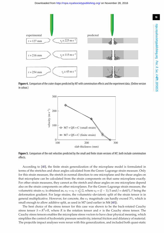
(c) Comminution effectsParameter A1 was calibrated by fitting one data point in figure 3, which led to the value A1 =3 × 10⁻⁷. The remaining points were then predicted. Figure 3 shows the predicted exit velocitiesfor all the four slabs tested. As can be seen, the predictions of exit velocities are reasonably good,for all the data points. For the smaller slabs, the exit velocity is slightly overestimated while forthe larger slab it is slightly underestimated. The fit could further be improved by relaxing theassumption that both the deviatoric and friction boundaries are scaled by the same factor. Butthis has not been explored as the errors are small and the data are too limited for calibrating twofactors. To further assess the predictions, the predicted crater shapes for the slabs are comparedwith the measured ones, as shown in figure 4. It can be seen that the shapes can be matchedvery well, especially those at the exit side. This serves to show that the proposed scaling of M7boundaries accounts for the phenomenon of comminution quite well.
(d) Finite strain effectsThe basic form of microplane model M7 applies only to small strains. In comminution, however,very large strains might occur. To deal with them, a finite strain generalization of the microplanemodel M4, a predecessor of M7, was proposed in [40]. The same generalization is possible formodel M7.
on November 28, 2016http://rspa.royalsocietypublishing.org/Downloaded from
Figure 4. Comparison of the crater shapes predicted byM7with comminution effects and the experiment data. (Online versionin colour.)
300
slab thickness (mm)
velo
city
(m
s–1)
200
100
0100 200
M7 + QS + C (small strain)
M7 + QS + C (finite strain)
300
Figure 5. Comparison of the exit velocities predicted by the small and finite strain versions of M7, both include comminutioneffects.
According to [40], the finite strain generalization of the microplane model is formulated interms of the stretches and shear angles calculated from the Green–Lagrange strain measure. Onlyfor this strain measure, the stretch in normal direction to one microplane and the shear angles onthat microplane can be calculated from the strain components on that same microplane exactly.For other strain measures, they cannot as the stretch and shear angles on one microplane dependalso on the strain components on other microplanes. For the Green–Lagrange strain measure, thevolumetric strain εV is obtained as, εV = ε0 + ε2
0/2, where ε0 = (J − 1)/3 and J = det(F), F being thedeformation gradient. For large strains, the volumetric–deviatoric split of the strain tensor is ingeneral multiplicative. However, for concrete, the εV magnitude can hardly exceed 3%, which issmall enough to allow additive split, as used in M7 (and earlier in M4 [40]).
The best choice of the stress tensor for this case was shown to be the back-rotated Cauchystress tensor S = RTσR, where R is the rotation tensor and σ is the Cauchy stress tensor. TheCauchy stress tensors enables the microplane stress vectors to have clear physical meaning, whichsimplifies the control of hydrostatic pressure sensitivity, internal friction and dilatancy of material.The projectile impact analyses were rerun with this generalization, and included both quasi-static
on November 28, 2016http://rspa.royalsocietypublishing.org/Downloaded from
rate effects, and the kinetic energy rate effect. The finite strain generalization did change theresults but not significantly, as seen in figure 5. The reason could be that even though the totalstrains are high, the rotations are not.
5. Conclusion(1) The microplane model M7 with boundaries modified according to the kinetic energy
theory of comminution is an effective approach to simulate projectile impact effects onconcrete slabs and offers possibilities of further refinement. It can accurately predictprojectile exit velocities, crater shapes and penetration depths.
(2) It is necessary to scale up the deviatoric and friction boundaries of M7, to achieve arate-dependent increase of the macroscopic deviatoric stress. Greater versatility couldbe obtained by scaling up the deviatoric and friction boundaries by different factors. Butthere are not enough test data to calibrate two independent factors.
(3) The scaling of the boundaries (or strength limits) must be proportional to both: (i) the−4/3 power of the effective deviatoric strain rate and (ii) the time derivative of that rate.
(4) The crack band model with a random tetrahedral mesh leads to accurate predictions ofthe crater shapes.
(5) An element deletion threshold is necessary to run impact analyses. The choice of thethreshold has a significant effect on the results. Chosen is a high enough threshold formaximum principal strain such that a further increase would not change the resultsappreciably.
(6) The finite strain generalization of the microplane model did not have a significant effecton the predicted exit velocities, perhaps because the material rotations were not too high.
(7) What is most important is that the finite-element code dissipate the correct energyrequired by the kinetic theory of comminution. But how exactly this energy is dissipateddoes not seem important. Dissipation modes in terms of additional viscosity, ratedependence of interface fracture, and scaling of strength limits give similar results. Whilethe viscosity approach is more natural for rate-dependent stress, the present approachhas the advantage of greater versatility for further refinements, such as the possibility ofdifferent scalings of different microplane boundaries, which might be needed for variousextensions such as hypervelocity impact, impact on rock, or explosive comminution ofrock, e.g. shale.
Data accessibility. All the test data used were taken from the open literature.Authors’ contributions. The first author, K.K. developed the formulation of boundary scaling in detail,implemented it as an Abaqus subroutine, conducted the finite-element analyses test data fitting and wrotethe first draft of the paper. The second author Y.S. contributed in the development of the formulation viatechnical discussions, provided the finite-element meshes and also reviewed and improved the draft. Thecorresponding author Z.P.B. conceived the basic idea of kinetic energy release from finite-size particles,directed the work and finalized the text. All the authors approved the publication.Conflict of interests. We declare we have no conflicting interests.Funding. Support under grant no. W911NF-15-1-0240 from the US Army Research Office, Durham, toNorthwestern University, is gratefully acknowledged.Acknowledgements. Thanks are due to Ferhun Caner, Visiting Scholar at Northwestern University, on leave fromUPC, Barcelona, for making available his coding of M7 and the meshes for slab perforations. The secondauthor acknowledges the support from Chinese Academy of Sciences via the ‘Hundred Talent program’ andsupport from NSFC (No. 11572323)
References1. Cadoni E, Labibes K, Albertini C, Berra M, Giangrasso M. 2001 Strain-rate effect on the
tensile behaviour of concrete at different relative humidity levels. Mater. Struct. 34, 21–26.(doi:10.1007/BF02482196)
on November 28, 2016http://rspa.royalsocietypublishing.org/Downloaded from
2. Camacho G, Ortiz M. 1996 Computational modelling of impact damage in brittle materials.Int. J. Solids Struct. 33, 2899–2938. (doi:10.1016/0020-7683(95)00255-3)
3. Deshpande V, Evans A. 2008 Inelastic deformation and energy dissipation in ceramics:a mechanism-based constitutive model. J. Mech. Phys. Solids 56, 3077–3100. (doi:10.1016/j.jmps.2008.05.002)
4. Doyoyo M. 2002 A theory of the densification-induced fragmentation in glasses andceramics under dynamic compression. Int. J. Solids Struct. 39, 1833–1843. (doi:10.1016/S0020-7683(01)00278-5)
5. Ferri E, Deshpande V, Evans A. 2010 The dynamic strength of a representative double layerprismatic core: a combined experimental, numerical, and analytical assessment. J. Appl. Mech.77, 061011. (doi:10.1115/1.4000905)
6. Forquin P, Gary G, Gatuingt F. 2008 A testing technique for concrete under confinement athigh rates of strain. Int. J. Impact Eng. 35, 425–446. (doi:10.1016/j.ijimpeng.2007.04.007)
7. Adley MD, Frank AO, Danielson KT. 2012 The high-rate brittle microplane concrete model.I. Bounding curves and quasi-static fit to material property data. Comput. Concrete 9, 293–310.(doi:10.12989/cac.2012.9.4.293)
8. Frank AO, Adley MD, Danielson KT, McDevitt Jr HS. 2012 The high-rate brittle microplaneconcrete model. II. Application to projectile perforation of concrete slabs. Comput. Concrete 9,311–325. (doi:10.12989/cac.2012.9.4.311)
9. Gailly BA, Espinosa HD. 2002 Modelling of failure mode transition in ballistic penetrationwith a continuum model describing microcracking and flow of pulverized media. Int. J.Numer. Methods Eng. 54, 365–398. (doi:10.1002/nme.427)
10. Gatuingt F, Pijaudier-Cabot G. 2002 Coupled damage and plasticity modelling in transientdynamic analysis of concrete. Int. J. Numer. Anal. Methods Geomech. 26, 1–24. (doi:10.1002/nag.188)
11. Grady D. 1982 Local inertial effects in dynamic fragmentation. J. Appl. Phys. 53, 322–325.(doi:10.1063/1.329934)
12. Grady D. 1998 Shock-wave compression of brittle solids. Mech. Mater. 29, 181–203.(doi:10.1016/S0167-6636(98)00015-5)
13. Grady D, Kipp M. 1979 The micromechanics of impact fracture of rock. Int. J. Rock Mech.Mining Sci. Geomech. Abs. 16, 293–302. (doi:10.1016/0148-9062(79)90240-7).
14. Grady D, Kipp M. 1995 Experimental measurement of dynamic failure and fragmentationproperties of metals. Int. J. Solids Struct. 32, 2779–2791. (doi:10.1016/0020-7683(94)00297-A)
15. Grady DE. 1990 Particle size statistics in dynamic fragmentation. J. Appl. Phys. 68, 6099–6105.(doi:10.1063/1.347188)
16. Kožar I, Ožbolt J. 2010 Some aspects of load-rate sensitivity in visco-elastic microplane model.Comps. Conc. 7, 317–329. (doi:10.12989/cac.2010.7.4.317)
17. Mescall J, Weiss V. 1984 Materials behavior under high stress and ultrahigh loading rates.II. In Proc. 29th Sagamore Army Conference. Watertown, MA: Army Materials and MechanicsCenter.
18. Mott N. 1947 Fragmentation of shell cases. Proc. R. Soc. Lond. A 189, 300–308. (doi:10.1098/rspa.1947.0042)
19. Ožbolt J, Sharma A, Reinhardt H-W. 2011 Dynamic fracture of concrete – compact tensionspecimen. Int. J. Solids Struct. 48, 1534–1543. (doi:10.1016/j.ijsolstr.2011.01.033)
20. Shih C, Nesterenko V, Meyers M. 1998 High-strain-rate deformation and comminution ofsilicon carbide. J. Appl. Phys. 83, 4660–4671. (doi:10.1063/1.367252)
21. Wei Z, Evans A, Deshpande V. 2009 The influence of material properties and confinementon the dynamic penetration of alumina by hard spheres. J. Appl. Mech. 76, 051305.(doi:10.1115/1.3129765)
22. Freund LB. 1990 Dynamic fracture mechanics. Cambridge, UK: Cambridge University Press.23. Shockey DA, Curran DR, Seaman L, Rosenberg JT, Petersen CF. 1974 Fragmentation of rock
under dynamic loads. Int. J. Rock Mech. Sci. Geomech. Abstr. 11, 303–317. (doi:10.1016/0148-9062(74)91760-4)
24. Hemmert DJ, Smirnov VI, Awal R, Lati S, Shetty A. 2010 Pulsed power generated shockwavesin liquids from exploding wires and foils for industrial applications. In Proc. of the 16th Int.Symp. on High Current Electronics, Tomsk, Russia, pp. 537–540.
25. Maurel O, Reess T, Matallah M, DeFerron A, Chen W, La Borderie C, Pijaudier-Cabot G,Jacques A, Rey-Bethbeder F. 2010 Electrohydraulic shock wave generation as a means to
on November 28, 2016http://rspa.royalsocietypublishing.org/Downloaded from
26. Reinhardt HW, Weerheijm J. 1991 Tensile fracture of concrete at high loading rates takingaccount of inertia and crack velocity effects. Int. J. Fract. 51, 31–42. (doi:10.1007/BF00020851)
27. Bažant ZP, Caner FC. 2014 Impact comminution of solids due to local kinetic energy of highshear strain rate. I. Continuum theory and turbulence analogy. J. Mech. Phys. Solids 64, 223–235. (doi:10.1016/j.jmps.2013.11.008)
28. Caner FC, Bažant ZP. 2014 Impact comminution of solids due to local kinetic energy of highshear strain rate. II. Microplane model and verification. J. Mech. Phys. Solids 64, 236–248.(doi:10.1016/j.jmps.2013.11.009)
29. Bažant ZP, Caner FC. 2013 Comminution of solids caused by kinetic energy of high shearstrain rate, with implications for impact, shock, and shale fracturing. Proc. Natl Acad. Sci. USA110, 19 291–19 294. (doi:10.1073/pnas.1318739110)
30. Su Y, Bažant ZP, Zhao Y, Salviato M, Kirane K. 2015 Viscous energy dissipation of kineticenergy of particles comminuted by high-rate shearing in projectile penetration, with potentialramification to gas shale. Int. J. Fract. 193, 77–85. (doi:10.1007/s10704-015-0019-0)
31. Bažant ZP, Su Y. 2015 Impact comminution of solids due to progressive crack growth drivenby kinetic energy of high-rate shear. ASME J. Appl. Mech. 82, 031007. (doi:10.1115/1.4029636)
32. Schuhmann Jr R. 1940 Principles of comminution, I-size distribution and surface calculations.AIME Technical Publication 1189.
33. Caner FC, Bažant ZP. 2012 Microplane model M7 for plain concrete. I. Formulation. J. Eng.Mech. 139, 1714–1723. (doi:10.1061/(ASCE)EM.1943-7889.0000570)
34. Caner FC, Bažant ZP. 2012 Microplane model M7 for plain concrete. II. Calibration andverification. J. Eng. Mech. 139, 1724–1735. (doi:10.1061/(ASCE)EM.1943-7889.0000571)
35. Bažant ZP, Caner FC, Carol I, Adley MD, Akers SA. 2000 Microplane model M4 forconcrete. I. Formulation with work-conjugate deviatoric stress. J. Eng. Mech. 126, 944–953.(doi:10.1061/(ASCE)0733-9399(2000)126:9(944))
36. Bažant ZP, Caner FC, Adley MD, Akers SA. 2000 Fracturing rate effect and creep inmicroplane model for dynamics. ASCE J. Eng. Mech. 126, 962–970. (doi:10.1061/(ASCE)0733-9399(2000)126:9(962))
37. Cargile JD. 1999 Development of a constitutive model for numerical simulation of projectilepenetration into brittle geomaterials. Report no. SL-99-11. Vicksburg, MS: US Army EngineeringResearch and Development Center.
38. Bažant ZP, Oh B-H. 1983 Crack band theory for fracture of concrete. Materials and structures(RILEM, Paris) 16, 155–177.
39. Cervenka J, Bažant ZP, Wierer M. 2005 Equivalent localization element for crack bandapproach to mesh-sensitivity in microplane model. Int. J. Numer. Methods Eng. 62, 700–726.(doi:10.1002/nme.1216)
40. Bažant ZP, Adley MD, Carol I, Jirasek M, Akers SA, Rohani B, Cargile JD, Caner FC. 2000Large strain generalization of microplane model for concrete and application. ASCE J. Eng.Mech. 126, 971–980. (doi:10.1061/(ASCE)0733-9399(2000)126:9(971))
on November 28, 2016http://rspa.royalsocietypublishing.org/Downloaded from