10/22/2011 1 ACI WEB SESSIONS Strengthening of Masonry Structures ACI Spring 2011 Convention April 3 - 7, Tampa, FL ACI WEB SESSIONS ACI Web Sessions The audio for this web session will begin momentarily and will play in its entirety along with the slides. However, if you wish to skip to the next speaker, use the scroll bar at left to locate the speaker’s first slide (indicated by the icon in the bottom right corner of slides 10 and 39). Click on the thumbnail for the slide to begin the audio for that portion of the presentation. Note: If the slides begin to lag behind the audio, back up one slide to re-sync. ACI WEB SESSIONS ACI Web Sessions ACI is bringing you this Web Session in keeping with its motto of “Advancing Concrete Knowledge.” The ideas expressed, however, are those of the speakers and do not necessarily reflect the views of ACI or its committees. Please adjust your audio to an appropriate level at this time. ACI WEB SESSIONS ACI Web Sessions ACI Web Sessions are recorded at ACI conventions and other concrete industry events. At regular intervals, a new set of presentations can be viewed on ACI’s website free of charge. After one week, the presentations will be temporarily archived on the ACI website or made part of ACI’s Online CEU Program, depending on their content. ACI WEB SESSIONS ACI Online CEU Program ACI offers an easy-to-use Online CEU Program for anyone who needs to earn Continuing Education credits. Once registered, you can download and study reference material. After passing a 10-question exam on the material, you will receive a certificate of completion that you can present to local licensing agencies. Visit www.concrete.org/education/edu_online_CEU.htm for more information. ACI WEB SESSIONS ACI Conventions ACI conventions provide a forum for networking, learning the latest in concrete technology and practices, renewing old friendships, and making new ones. At each of ACI’s two annual conventions, technical and educational committees meet to develop the standards, reports, and other documents necessary to keep abreast of the ever-changing world of concrete technology. With over 1,300 delegates attending each convention, there is ample opportunity to meet and talk individually with some of the most prominent persons in the field of concrete technology. For more information about ACI conventions, visit www.aciconvention.org.
Transcript
10/22/2011
1
ACI WEB SESSIONS
Strengthening of Masonry Structures
ACI Spring 2011 ConventionApril 3 - 7, Tampa, FL
ACI WEB SESSIONS
ACI Web SessionsThe audio for this web session will begin momentarily and will play in its entirety along with the slides.
However, if you wish to skip to the next speaker, use the scroll bar at left to locate the speaker’s first slide (indicated by theicon in the bottom right corner of slides 10 and 39). Click on the thumbnail for the slide to begin the audio for that portion of the presentation.
Note: If the slides begin to lag behind the audio, back up one slide to re-sync.
ACI WEB SESSIONS
ACI Web Sessions
ACI is bringing you this Web Session in keeping with its motto of “Advancing Concrete Knowledge.” The ideas expressed, however, are those of the speakers and do not necessarily reflect the views of ACI or its committees.
Please adjust your audio to an appropriate level at this time.
ACI WEB SESSIONS
ACI Web Sessions
ACI Web Sessions are recorded at ACI conventions and other concrete industry events. At regular intervals, a new set of presentations can be viewed on ACI’s website free of charge.
After one week, the presentations will be temporarily archived on the ACI website or made part of ACI’s Online CEU Program, depending on their content.
ACI WEB SESSIONS
ACI Online CEU ProgramACI offers an easy-to-use Online CEU Program for anyone who needs to earn Continuing Education credits.
Once registered, you can download and study reference material. After passing a 10-question exam on the material, you will receive a certificate of completion that you can present to local licensing agencies.
Visit www.concrete.org/education/edu_online_CEU.htmfor more information.
ACI WEB SESSIONS
ACI ConventionsACI conventions provide a forum for networking, learning the latest in concrete technology and practices, renewing old friendships, and making new ones. At each of ACI’s two annual conventions, technical and educational committees meet to develop the standards, reports, and other documents necessary to keep abreast of the ever-changing world of concrete technology.
With over 1,300 delegates attending each convention, there is ample opportunity to meet and talk individually with some of the most prominent persons in the field of concrete technology. For more information about ACI conventions, visit www.aciconvention.org.
10/22/2011
2
ACI WEB SESSIONS
Fall 2011 SeminarsThese seminars, cosponsored by ACI and the Portland Cement Association (PCA), will cover all the major changes in the new edition of the 318-11 Building Code.
For more information, visit ACI seminars.
DATE LOCATION
November 3 Charlotte, NCNovember 8 Boston, MANovember 10 Detroit, MINovember 15 Des Moines, IANovember 17 Portland, ORNovember 29 Denver, CODecember 1 Phoenix, AZDecember 6 Atlanta, GADecember 8 Washington, DCDecember 13 Dallas, TXDecember 15 San Francisco, CA
DATE LOCATION
September 13 Chicago, ILSeptember 27 Philadelphia, PASeptember 29 Houston, TXOctober 4 Seattle, WAOctober 6 Los Angeles, CAOctober 11 New York, NYOctober 13 Minneapolis, MNOctober 20 Cincinnati, OHOctober 25 New Brunswick, NJOctober 27 St. Louis, MONovember 1 Orlando, FL
ACI WEB SESSIONS
ACI Web Sessions
This ACI Web Session includes two speakers presenting at the ACI spring convention held in Tampa, FL April 3 – 7, 2011.
Additional presentations will be made available in future ACI Web Sessions.
Please enjoy the presentations.
ACI WEB SESSIONS
Strengthening of Masonry Structures
ACI Spring 2011 ConventionApril 3 - 7, Tampa, FL
ACI WEB SESSIONS
Lawrence C. Bank, ACI member and professor in the Department of Civil and Environmental Engineering at the University of Wisconsin in Madison. Dr. Bank’s primary research is in the area of the mechanics and design of composite material structures with an emphasis on applications to civil engineering. He is the author of the textbook Composites for Construction: Structural Design with FRP Materials. He is a member of ACI Committee 440 – Fiber-Reinforced Polymer Reinforcement.
ACI WEB SESSIONS
Experimental studies of mechanically fastenedFRP systems: state-of-the-art
V.L. Brown, L.C. Bank*, D. Arora, D.T. Borowicz, A. Godat,A.J. Lamanna, J. Lee, F. Matta, A. Napoli, K.-H. Tan
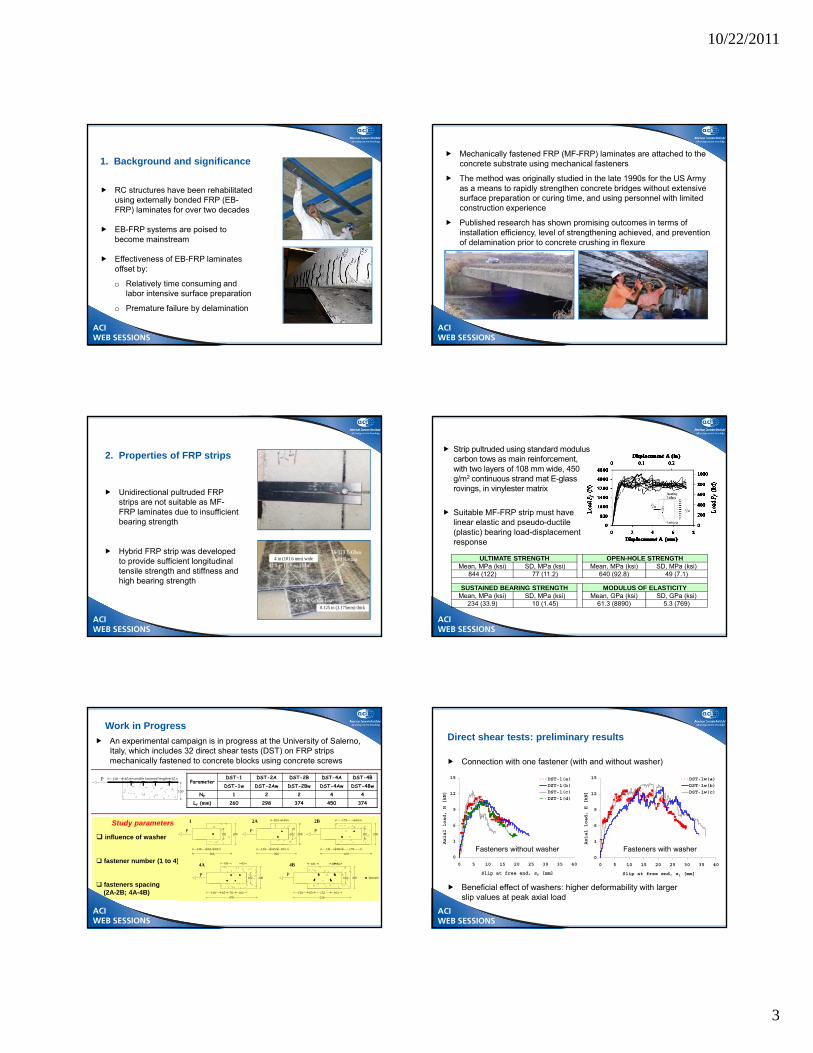
RC structures have been rehabilitated using externally bonded FRP (EB-FRP) laminates for over two decades
EB-FRP systems are poised to become mainstream
Effectiveness of EB-FRP laminates offset by:
o Relatively time consuming and labor intensive surface preparation
o Premature failure by delamination
1. Background and significance
ACI WEB SESSIONS
Mechanically fastened FRP (MF-FRP) laminates are attached to the concrete substrate using mechanical fasteners
The method was originally studied in the late 1990s for the US Army as a means to rapidly strengthen concrete bridges without extensive surface preparation or curing time, and using personnel with limited construction experience
Published research has shown promising outcomes in terms of installation efficiency, level of strengthening achieved, and prevention of delamination prior to concrete crushing in flexure
ACI WEB SESSIONS
ACI WEB SESSIONS
Unidirectional pultruded FRP strips are not suitable as MF-FRP laminates due to insufficient bearing strength
Hybrid FRP strip was developed to provide sufficient longitudinal tensile strength and stiffness and high bearing strength
Strip pultruded using standard modulus carbon tows as main reinforcement, with two layers of 108 mm wide, 450 g/m2 continuous strand mat E-glass rovings, in vinylester matrix
Suitable MF-FRP strip must have linear elastic and pseudo-ductile (plastic) bearing load-displacement response
ACI WEB SESSIONS
FRPRCS-10 | April 3, 2011
An experimental campaign is in progress at the University of Salerno, Italy, which includes 32 direct shear tests (DST) on FRP strips mechanically fastened to concrete blocks using concrete screws
Early study by Lamanna (2002) on 35 scaled (152 x 152 x 1220 mm) RC beams. Feasibility was evaluated using different fasteners and layouts, and different FRP laminates
12 larger scale beams (305 x 305 x 3660 mm) were then tested (Lamanna 2002, Bank et al. 2002) to study influence of fastener type and spacing, pre-drilling of FRP strips, and type and number of FRP strips
Additional 9 beams (305 x 305 x 3660 mm) were tested (Borowicz 2002, Bank et al. 2002) to study anchorage length, shear spans, fatigue loads, and type and number of FRP strips
Lamanna (2002)
Lamanna (2002), Bank et al. (2002)
ACI WEB SESSIONS
Six full-scale T-beams were tested (Borowicz 2002, Bank et al. 2002), followed by additional 5 specimens (Bank et al. 2004), to investigate:
o Concrete expansion anchors at the FRP strip ends to prevent delamination
o Use of multiple FRP strips, also investigated by Arora (2003)
Borowicz (2002)
Fastener types and layouts were studied by Lee et al. (2009) drawing evidence from tests on three beam specimens (150 x 200 x 1520 mm)
ACI WEB SESSIONS
Ductile failure mode by concrete crushing after steel yield, with FRP strips firmly attached
With appropriate fastener layout and FRP strip properties, the strength increase is equal to that of EB-FRP strengthened beams, with a slightly lesser stiffness but with a much greater ductility
Use of multiple FRP strips in unbonded layers does not yield significant increases in capacity over that of beams strengthened with a single strip, attributed to premature end-delamination and fasteners’ inability to transfer load into the outer strips
Strains in the FRP are smaller than predicted by the fully bonded assumption, leading to the conclusion that slip accommodated by nail rotation decreases strengthening effectiveness
General conclusions
ACI WEB SESSIONS
An MF-FRP strengthened beam (MFP2) was tested and compared to (Galati et al. 2007):
o 2 beams strengthened by epoxy bonded unidirectional CFRP pre-cured laminates (BP1 epoxy only, and BP1-A1 with fiber anchor spikes)
o a beam using the same hybrid pre-cured laminate bonded with epoxy and with steel anchors at the strip ends (BP2-A2)
Tests by Galati et al. (2007)
6 concrete beams (305 x 305 x 3657 mm) were strengthened (Martin & Lamanna 2004) using relatively large diameter (12.7mm ) concrete screws to investigate:
o the effect of fastener number, spacing, and pattern
ACI WEB SESSIONS
10/22/2011
5
ACI WEB SESSIONS
Layouts: 2
Diameter: 9.5 mm
Length: 44.5 mm
Anchors
1219 610 3658
152
1219
Load 0.5F 0.5F
305 127
#4 (Ø12.7) steel bars
102
Pattern No. 1
64 5 @ 76 31
102
52
25
25
CL
102
Pattern No. 2
64 5 @ 76 31
102
52
25
25
L
MF-2-S
EB
Control
MF-2-LMF-1-L
05
10152025303540
0 20 40 60 80 100
Mom
ent
(k
N-m
)
Midspan displacement (mm)
MF-1-S
Scaled one-way RC slabs tested by Napoli et al. (2010)
Ultimate strength levels were comparable to that of a benchmark slab strengthened with an externally bonded (EB) carbon FRP laminate, with greater deformability
Specimens that used a larger number of anchors in the shear span, MF-1L and MF-1S, achieved marginally larger ultimate strengths but at lesser deformability than corresponding slabs MF-2L and MF-2S
ACI WEB SESSIONS
Two series of wide shallow beams (203 x 152 x 2290 mm) were tested at Widener University (Marks et al. 2007; Fung et al. 2010)
The beams were strengthened with FRP laminates mechanically fastened with expansion anchor bolts.
Parameters such as bolt diameter and spacing, and FRP strip length were varied to determine the effect upon strengthening level, ductility, and failure modes
The number of fasteners in the shear span had an equal or greater impact on ultimate strength than did FRP strip length
0
5
10
15
20
25
30
35
0 5 10 15 20 25 30
Mom
ent
(kN
-m)
Number of anchor bolts in shear span
Phase I Beams
Phase II Beams
0
5
10
15
20
25
30
35
0.0 0.5 1.0 1.5 2.0 2.5
Mom
ent
(k
N-m
)
Length of FRP Strip (m)
Phase I Beams
Phase II Beams
(Fung et al. 2010)
ACI WEB SESSIONS
As with PAFs, the efficiency of concrete screws is affected by hard aggregates
The gradual bearing failure of screws through the FRP strip, coupled with yielding of steel reinforcement, produces significant deflections
The ultimate strength levels are comparable to those of EB-FRP strengthened slabs, with greater deformability
Increasing the numbers of anchors, specimens achieve marginally larger ultimate strengths but at lesser deformability
The number of fasteners in the shear span has an equal or greater impact on ultimate strength than does FRP strip length
FRP strains are less than those calculated assuming fully bonded conditions; strain efficiency tends to increase as the number of anchor bolts increases
General conclusions
ACI WEB SESSIONS
Fatigue Tests
6 beams (152 x 254 x 4750 mm) were tested under midpoint flexure (Quattlebaum et al. 2005)
o # 3 flexural retrofit systems compared: MF-FRP, near-surface mounted (NSM), and adhesively bonded (EB) systems
o MF-FRP strengthened beams outperformed NSM-FRP and EB-FRP strengthened beams in high-stress range fatigue life
o For beams subjected to low-stress fatigue, the MF-FRP strengthened beam showed less damage compared to the EB-FRP one
2 beams (305 x 305 x 1370 mm) were subjected to cyclic loading between 20 and 80% of unstrengthened beam capacity at a 2 Hz frequency in four-point bending (Borowicz 2002)
o FRP showed no signs of degradation, and fasteners remained firmly embedded in concrete
1 full-size T beam was tested between 44.5 and 133.4 kN at 2 Hz for 2,000,000 cycles without beam failure (Bank et al. 2004a)
o no FRP or fastener wear was noted
ACI WEB SESSIONS
1 beam (254 x 165 x 1830 mm) was cycled between 33 and 63% of the theoretical ultimate flexural capacity, at a frequency of 2 Hz, and survived two million cycles (Ekenel at al. 2006)
o The increase in ductility was 3.5 times that of the beam strengthened with EB-FRP system
Test by Tan & Saha (2007) 6 beams (100 x 125 x 2000 mm) were cycled between 35% and 55-85% of the static flexural strength of the strengthened beams, at a frequency of 2 Hz (Tan & Saha 2007)
o Study of the serviceability behavior
o The stiffness of the strengthened beams was found to degrade quickly
ACI WEB SESSIONS
ACI WEB SESSIONS
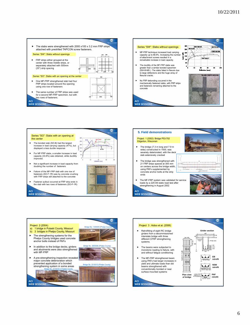
The second series (“SO”) comprised four slabs with central cut-outs measuring 800 x 800mm (32”x 32”) and line loading around the cut-out
4. Two-way slabs
Two series of large-scale slabs (2600 x 2600 x 120 mm) were tested at the Helwan University (Cairo, Egypt) with different strengthening patterns (Elsayed et al 2009a, 2008b)
The first series (“SW”) included five slabs without openings
ACI WEB SESSIONS
10/22/2011
6
ACI WEB SESSIONS
2000200 200
2000200 200
500 500
The slabs were strengthened with 2000 x100 x 3.2 mm FRP strips attached with predrilled TAPCON screw fasteners.
FRP strips either grouped at the center with three middle strips, or separately attached with 500mm (20”) strip spacing
2000200 200
950
One MF-FRP strengthened slab had four FRP strips located around the opening using one row of fasteners
The same number of FRP strips was used for a second MF-FRP specimen, but with two rows of fasteners.
Series “SW”: Slabs without openings
Series “SO”: Slabs with an opening at the center
ACI WEB SESSIONS
MF-FRP technique increased load carrying capacity up to 66.9%. Increasing the number of attachment screws resulted in a remarkable increase in load capacity
The ductility of the MF-FRP slabs was greater than a similar bonded specimen (SW-B-MS ). The slabs failed in flexure due to large deflections and the huge array of flexural cracks.
No FRP debonding occurred in the mechanically fastened slabs, with FRP strips and fasteners remaining attached to the concrete
SLAB SW-F-MS-50
Series “SW”: Slabs without openings
ACI WEB SESSIONS
ACI WEB SESSIONS
The bonded slab (SO-B) had the largest increase in load carrying capacity (47%), but displayed a less ductile response
For MF-FRP slabs, a smaller increase in load capacity (33.8%) was obtained, while ductility improved.
Not a significant increase in load capacity from doubling the number of fasteners
Failure of the MF-FRP slab with one row of fasteners (SO-F-1R) was by concrete crushing with FRP strips still attached to the concrete
Fastener pullout occurred at FRP strip ends in the slab with two rows of fasteners (SO-F-1R)
Series “SO”: Slabs with an opening at the center
SLAB SO-F-2R
ACI WEB SESSIONS
5. Field demonstrations
The bridge (7.3 m long and 7.9 m wide) constructed in 1930, was severely deteriorated, with the deck slab extensively cracked
The bridge was strengthened with 21 FRP strips spaced at 305 mm on centers across the bridge width, using PAFs supplemented by concrete anchor bolts at the strip ends
The MF-FRP system was validated for service loads by a 225 kN static load test after strengthening in August 2002
ACI WEB SESSIONS
ACI WEB SESSIONS
Project 2 (2004): a) 1 bridge in Pulaski County, Missourib) 3 bridges in Phelps County, Missouri
The strengthening systems for the Phelps County bridges used concrete anchor bolts instead of PAFs
In addition to the bridge decks, girders and abutments were also strengthened with MF-FRP
A pre-strengthening inspection revealed major concrete deterioration which prevented application of a bonded strengthening system in some areas
Bridge No. 3855006 (Phelps County)
Bridge No. 1330005 (Phelps County)
Bridge No. 2210010 (Phelps County)
FRPRCS-10 | April 3, 2011
Bridge No. 2210010 in Pulaski County
ACI WEB SESSIONS
ACI WEB SESSIONS
Project 3 : Aidoo et al. (2006)
Retrofitting of eight RC bridge girders from a decommissioned interstate bridge with three different CFRP strengthening systems.
The beams were subjected to monotonic loading to failure, with and without fatigue conditioning
The MF-FRP strengthened beam using PAFs had larger increases in yield and ultimate loads than did beams strengthened with conventionally bonded or near surface mounted systems
Girder section
NSMretrofit
PAF retrofit
Plan viewof bridge
EBretrofit
10/22/2011
7
ACI WEB SESSIONS
An overview of the experimental research on the MF-FRP method has been presented
A database of collected test results has been assembled to provide a convenient source of information on published test data on the performance of MF-FRP strengthened beams and one-way slabs
It can be concluded that the MF-FRP method is a viable technique for strengthening concrete members, particularly where speed of installation and immediacy of use are imperative, or where strengthening is intended as a temporary measure
The method is particularly attractive because little surface preparation is required and a pseudo-ductile failure mode is obtained
6. Conclusions
ACI WEB SESSIONS
Acknowledgements Charles Bakis and Maria Lopez de Murphy, Penn State
Walid Elsayed, Helwan University
Nestore Galati, Structural Preservation Systems
Kent Harries, University of Pittsburgh
Antonio Nanni, University of Miami
Kenneth Neale, Université de Sherbrooke
Roberto Realfonzo, University of Salerno
Andrea Rizzo, University of Lecce
ACI WEB SESSIONS
J. Gustavo Tumialan, ACI Member, is a Senior Project Manager at Simpson Gumpertz and Heger, Inc. in Boston, MA. He received his B.S. in Civil Engineering from Pontificia Universidad Catolica del Peru; and MSc. and Ph.D. from the Missouri University of Science and Technology. He specializes in the investigation, evaluation, and rehabilitation of structures. He is a member of ACI Committees 437 -Finite Element Analysis of Reinforced Concrete Structures--Joint ACI-ASCE; 440 - Fiber-Reinforced Polymer Reinforcement; and 562 - Evaluation, Repair, and Rehabilitation of Concrete Buildings. He was a member of the Task Group that prepared ACI 440.7R-10.
ACI WEB SESSIONS
ACI Design Guide for Flexural and Shear Strengtheningof URM Walls with FRP Systems
Gustavo TumialanSimpson Gumpertz & Heger, Inc., Boston, MA
Will GoldBASF Corp. – Building Systems, Cleveland, OH
Nestore GalatiStructural Group, Elkridge, MD
Andrea ProtaUniversity of Naples Federico II, Italy
ACI WEB SESSIONS
ACI WEB SESSIONS
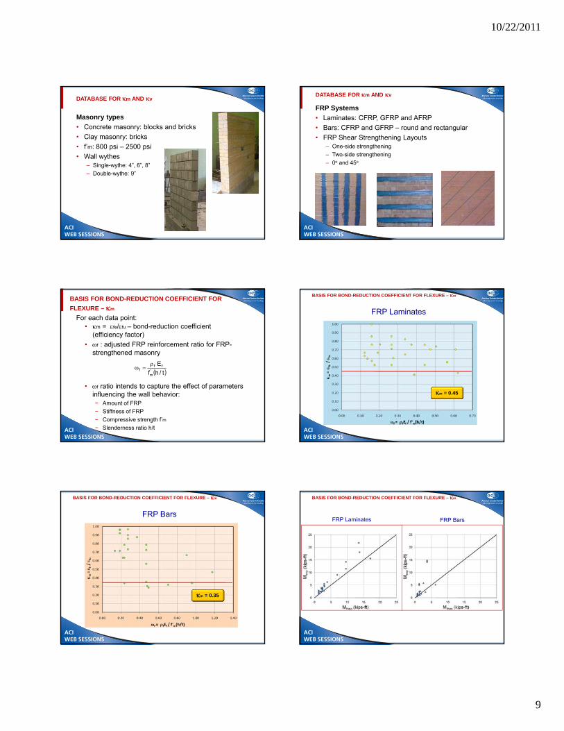
INTRODUCTION
• Unreinforced masonry (URM) structures are prone to extensive damage due to loads from wind, earthquake or man-made events– FRP composites can offer solutions for masonry strengthening
• Need for masonry strengthening requires development of guides for design, handling and installation of the externally bonded FRP systems
• In 2010, the ACI Committee 440 published “Guide for the Design and Construction of Externally Bonded FRP Systems for Unreinforced Masonry Structures” (ACI 440.7R-10) – Flexural Strengthening
– Shear Strengthening ACI WEB SESSIONSACI WEB SESSIONS
10/22/2011
8
ACI WEB SESSIONS
FLEXURAL STRENGTHENING OF URM WITH FRP SYSTEMS
• FRP composite systems are very effective for strengthening of URM walls that can behave as simply-supported elements, or very nearly so– Including “stocky” walls provided that the walls are not built
between rigid supports
• Walls with low h/t ratios (less than 12) and built between rigid supports can develop arching action– FRP not very effective
• Walls able to develop arching do not typically require to be strengthened, and therefore are not addressed by ACI 440.7R-10
ACI WEB SESSIONS
What is Arching Action?
F
FHFV
ACI WEB SESSIONS
SHEAR STRENGTHENING OF URM WITH FRP SYSTEMS
• Walls under in-plane loads can have the following four modes of failure:– Diagonal tension (force-controlled failure)
– Bed-joint sliding (force-controlled failure)
– Toe crushing (force-controlled failure)
– Rocking (deformation-controlled failure)
Diagonal TensionBrittle Failure
Bed-joint slidingBrittle Failure
RockingDuctile Failure
Toe crushingBrittle Failure
• Deformation-controlled failures are more ductile than force-controlled failures
ACI WEB SESSIONS
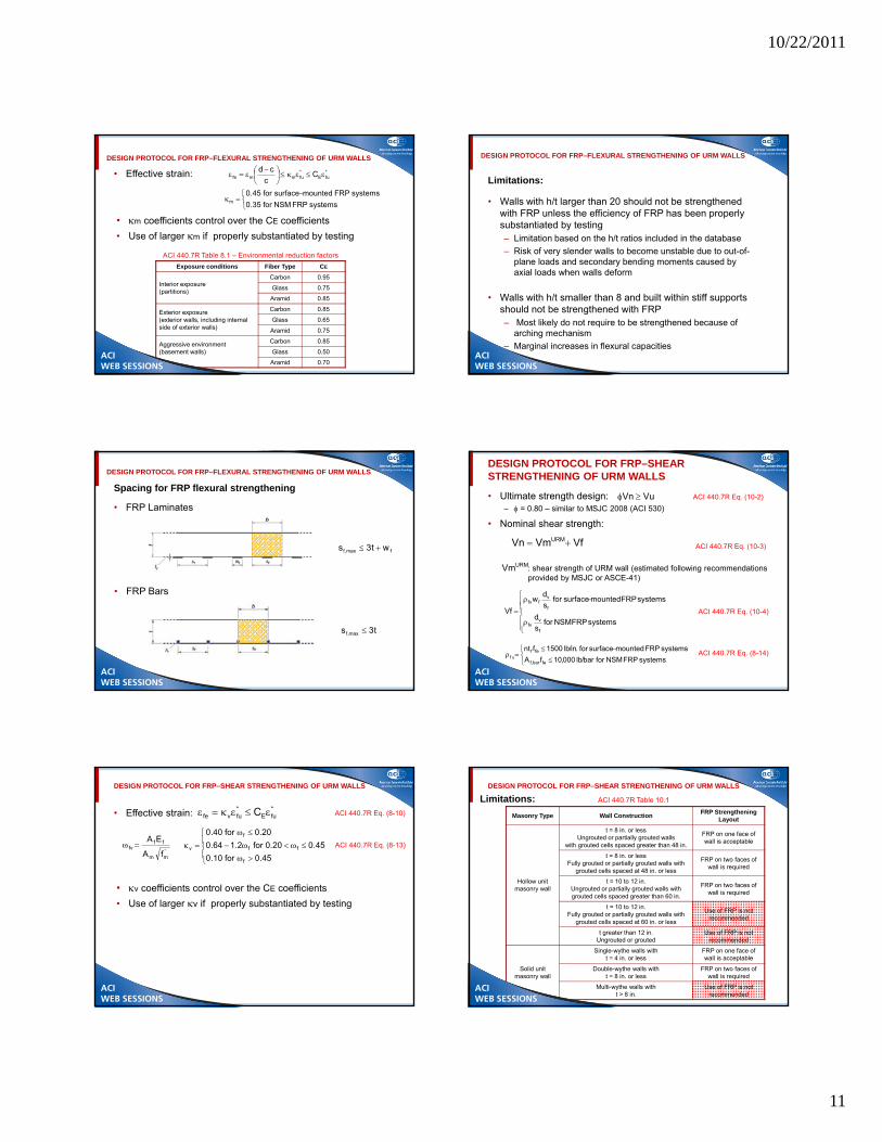
FRP EFFECTIVE STRAINS AT ULTIMATE
• Flexural strength of URM wall strengthened with FRP
• Shear strength of URM wall strengthened with FRP
• Use of larger m if properly substantiated by testing
ACI WEB SESSIONS
ACI WEB SESSIONS
DESIGN PROTOCOL FOR FRP–FLEXURAL STRENGTHENING OF URM WALLS
Limitations:
• Walls with h/t larger than 20 should not be strengthened with FRP unless the efficiency of FRP has been properly substantiated by testing– Limitation based on the h/t ratios included in the database
– Risk of very slender walls to become unstable due to out-of-plane loads and secondary bending moments caused by axial loads when walls deform
• Walls with h/t smaller than 8 and built within stiff supports should not be strengthened with FRP– Most likely do not require to be strengthened because of
arching mechanism
– Marginal increases in flexural capacities
ACI WEB SESSIONS
DESIGN PROTOCOL FOR FRP–FLEXURAL STRENGTHENING OF URM WALLS
Spacing for FRP flexural strengthening
• FRP Laminates
• FRP Bars
fmax,f wt3s
t3s max,f
ACI WEB SESSIONS
DESIGN PROTOCOL FOR FRP–SHEAR STRENGTHENING OF URM WALLS
• Ultimate strength design:– = 0.80 – similar to MSJC 2008 (ACI 530)
VuVn ACI 440.7R Eq. (10-2)
• Nominal shear strength:
ACI 440.7R Eq. (10-3)VfVmVn URM
URMVm : shear strength of URM wall (estimated following recommendations provided by MSJC or ASCE-41)
systemsFRPNSMfors
d
systemsFRPmountedsurfacefors
dw
Vf
f
vfv
f
vffv
ACI 440.7R Eq. (10-4)
systemsFRPNSMforbar/lb000,10fA
systemsFRPmountedsurfacefor.in/lb1500fnt
febar,f
fefvf
ACI 440.7R Eq. (8-14)
ACI WEB SESSIONS
DESIGN PROTOCOL FOR FRP–SHEAR STRENGTHENING OF URM WALLS
• Effective strain:
• v coefficients control over the CE coefficients
• Use of larger v if properly substantiated by testing
*fuE
*fuvfe C
45.0for10.0
45.020.0for2.164.0
20.0for40.0
f
ff
f
v
ACI 440.7R Eq. (8-10)
ACI 440.7R Eq. (8-13)'mm
fffv
fA
EA
ACI WEB SESSIONS
DESIGN PROTOCOL FOR FRP–SHEAR STRENGTHENING OF URM WALLS
Limitations:
Masonry Type Wall ConstructionFRP Strengthening
Layout
Hollow unit masonry wall
t = 8 in. or lessUngrouted or partially grouted walls
with grouted cells spaced greater than 48 in.
FRP on one face of wall is acceptable
t = 8 in. or lessFully grouted or partially grouted walls with
grouted cells spaced at 48 in. or less
FRP on two faces of wall is required
t = 10 to 12 in.Ungrouted or partially grouted walls with grouted cells spaced greater than 60 in.
FRP on two faces of wall is required
t = 10 to 12 in.Fully grouted or partially grouted walls with
grouted cells spaced at 60 in. or less
Use of FRP is not recommended
t greater than 12 in.Ungrouted or grouted
Use of FRP is not recommended
Solid unit masonry wall
Single-wythe walls witht = 4 in. or less
FRP on one face of wall is acceptable
Double-wythe walls witht = 8 in. or less
FRP on two faces of wall is required
Multi-wythe walls witht > 8 in.
Use of FRP is not recommended
ACI 440.7R Table 10.1
ACI WEB SESSIONS
10/22/2011
12
ACI WEB SESSIONS
DESIGN PROTOCOL FOR FRP–SHEAR STRENGTHENING OF URM WALLS
Spacing for FRP shear strengthening
• FRP Laminates • FRP Bars
sf
sf
fmax,f w.in16s .in16s max,f
ACI WEB SESSIONS
SUGGESTED ANCHORAGE DETAILS
FRP Laminates FRP Bars
• Flexural strengthening – good engineering practice
ACI WEB SESSIONS
SUGGESTED ANCHORAGE DETAILS
• Shear strengthening - ensure continuity of load path
ACI WEB SESSIONS
FINAL REMARKS
• It is expected that strengthening of masonry with FRP systems will become more common with the availability of ACI guides
• Future work of ACI Sub-Committee 440M:
– Refine m and v values as more research results become available
– Develop design recommendations for shear strengthening of infill walls
ACI WEB SESSIONS
THANKS
ACI WEB SESSIONS
ACI WEB SESSIONS
Click on the image below to go to the web page.
Seminar Schedule Bookstore ACI Web Sessions Conventions
Online CEU Program ACI eLearning Concrete Knowledge