Supporting Information Strong Photocurrent Amplification in Perovskite Solar Cells with a Porous TiO 2 Blocking Layer under Reverse Bias Thomas Moehl a,* , Jeong Hyeok Im a,b , Yong Hui Lee a , Konrad Domanski a , Fabrizio Giordano a , Shaik M. Zakeeruddin a , Ibrahim M. Dar, a Leo-Philipp Heiniger a , Mohammad Khaja Nazeeruddin a , Nam- Gyu Park b and Michael Grätzel a a Laboratory of Photonics and Interfaces, Institute of Chemical Sciences and Engineering, École polytechnique fédérale de Lausanne (EPFL), Station 6, CH-1015 Lausanne, Switzerland b School of Chemical Engineering and Department of Energy Science, Sungkyunkwan University (SKKU), Suwon 440-746, Korea *Corresponding author: [email protected]Experimental section Spin coated TiO 2 blocking layer (devices Spin_1 and Spin_2 as well as Spin_Rutile_1 and Spin_Rutile_2): Pre-etched FTO glasses (Nippon Sheet Glass, NSG 10Ω) were cleaned in an ultrasonic bath containing ethanol for 30 min and were then treated in UV/Ozone cleaner for 30 min. TiO 2 blocking layer was spin-coated on FTO glasses at 2000 rpm for 20 s using 0.15 M titanium diisopropoxide bis(acetylacetonate) (75 wt.% in isopropanol, Aldrich) in 1-butanol (99.8%, Aldrich) solution. Afterwards, the coated FTO was heated at 125 o C for 5 min. For the SEMs and the electrochemical measurements the BL coated FTO was further heated to 550°C for 30 min - similarly to the subsequent heating step which is performed for the preparation of a complete photoanode after the deposition of the mesoporous TiO 2 particle layer (see solar cell fabrication B). Spray pyrolized TiO 2 blocking layer (devices Spray_1, Spray_2): Chemically etched FTO glass (NSG 10Ω, Nippon Sheet Glass) was sequentially cleaned with detergent solution, deionized water, acetone and ethanol under ultrasonication for 30 min. A 30 nm-thick TiO 2 blocking layer was deposited with diluted titanium diisopropoxide bis(acetylacetonate) solution (Sigma-Aldrich) in ethanol by spray pyrolysis at 450℃.
Transcript
Supporting Information
Strong Photocurrent Amplification in Perovskite
Solar Cells with a Porous TiO2 Blocking Layer
under Reverse Bias
Thomas Moehla,*, Jeong Hyeok Im
a,b, Yong Hui Lee
a, Konrad Domanski
a, Fabrizio Giordano
a, Shaik
M. Zakeeruddina, Ibrahim M. Dar,a Leo-Philipp Heinigera, Mohammad Khaja Nazeeruddina, Nam-
Gyu Parkb and Michael Grätzel
a
aLaboratory of Photonics and Interfaces, Institute of Chemical Sciences and Engineering, École polytechnique fédérale de Lausanne (EPFL), Station 6, CH-1015 Lausanne, Switzerland
bSchool of Chemical Engineering and Department of Energy Science, Sungkyunkwan University (SKKU), Suwon 440-746, Korea
(NSG 10Ω, Nippon Sheet Glass) was sequentially cleaned with detergent solution, deionized water,
acetone and ethanol under ultrasonication for 30 min. A 30 nm-thick TiO2 blocking layer was
deposited with diluted titanium diisopropoxide bis(acetylacetonate) solution (Sigma-Aldrich) in
ethanol by spray pyrolysis at 450.
Solar cell fabrication A:(spin coated and spray pyrolized BL with Dyesol 18 NRT paste, devices
Spin_1, Spin_2, Spray_1 and Spray_2): 350 nm-thick mesoporous TiO2 layers with Dyesol 18-NRT
paste (particle size: ∼20 nm; diluted with ethanol, 1:3.5 weight ratio) was made by spin coating at
5,000 rpm for 30 sec and heating at 500 for 30 min to burn organic components. The mesoporous
TiO2 film was immersed in 0.02 M aqueous TiCl4 (>98%, Aldrich) solution at 70oC for 30 min. After
washing with DI water and drying, the film was heated at 500oC for 30 min. Mesoporous film
thickness is about 300 to 400 nm. For the deposition of methylammonium lead iodide, 1.0 M of lead
iodide solution in N,N-dimethylformamide kept at 70 was firstly spin coated at 6,500 rpm for 30 sec
on mp-TiO2 electrode and then dried at 70 for 15 min. After cooling to room temperature, the film
was immersed in a solution of methylammonium iodide in isopropanol (8 mg ml-1) for 20 sec, shortly
rinsed with isopropanol and dried again at 70 for 15 min. The HTM solution was prepared by
dissolving 72.3 mg of (2,2`,7,7`-tetrakis(N,N-di-p-methoxyphenylamine)-9,9-spirobifluorene) (spiro-
MeOTAD), 28.8 uL of 4-tert-butylpyridine (TBP, Aldrich), 17.5 uL of a stock solution of 520 mg/mL
of lithium bis(trifluoromethylsulphonyl)imide in acetonitrile and 29 uL of a stock solution of 300
mg/mL of tris(2-(1H-pyrazol-1-yl)-4-tert-butylpyridine)cobalt(III) bis(trifluoromethylsulphonyl)imide
in acetonitrile in 1 mL of chlorobenzene. This solution was spin-coated at 4,000 rpm for 30 sec before
deposition of 60 nm-thick gold counter electrodes by evaporation method.
Solar cell fabrication B:(spin coated BL with rutile particle, devices Spin_rutile_1, Spin_Rutile_2
and the device without any kind of underlayer): After cooling down to room temperature from the last
heating step of the blocking layer fabrication, the TiO2 paste (ca. 40 nm rutile TiO2 particles made after
the recipe in by Lee et al.11) was spin coated on the BL layer at 2000 rpm for 10 s, where the pristine
paste was diluted in ethanol (0.1 g/mL). After drying at 100oC for 5 min, the film was annealed at
550oC for 30 min, which led to thickness of about 100 nm. The mesoporous TiO2 film was immersed
in 0.02 M aqueous TiCl4 (>98%, Aldrich) solution at 70oC for 30 min. After washing with DI water
and drying, the film was heated at 500oC for 30 min. CH3NH3PbI3 was formed using two-step spin
coating procedure. 1 M PbI2 solution was prepared by dissolving 462 mg PbI2 (99%, Aldrich) was
dissolved in 1 mL N,N-dimethylformamide (DMF) (99.8%, Sigma-Aldrich) under stirring at 70oC. 20
µL of PbI2 solution was spin-coated on the mesoporous TiO2 film at 3000 rpm for 5 s and 6000 rpm
for 5 s (without loading time). After spinning, the film was dried at 100oC for 10 min. After cooling
down to room temperature, 200 µL of 0.044 M (7 mg/mL) CH3NH3I solution in 2-propanol was
loaded on the PbI2-coated substrate for 20 s (loading time), which was spun at 4000 rpm for 20 s and
dried at 100oC for 5 min. 20 µL of spiro-MeOTAD solution was spin-coated on the CH3NH3PbI3
perovskite layer at 4000 rpm for 30 s. A spiro-MeOTAD solution was prepared by dissolving 72.3 mg
of spiro-MeOTAD in 1 mL of chlorobenzene, to which 28.8 µL of 4-tert-butyl pyridine and 17.5 µL of
lithium bis(trifluoromethanesulfonyl)imide (Li-TFSI) solution (520 mg LI-TSFI in 1 mL acetonitrile
(Sigma-Aldrich, 99.8%)) were added. Finally, 80 nm of gold was thermally evaporated on the spiro-
MeOTAD coated film.
The devices without any BL or underlayer were made similarly to the fabrication described in this
section without the deposition of the BL described in the first paragraph in the experimental part.
SEM: Film morphology was investigated by using a high-resolution scanning electron microscope
(Merlin, Zeiss) equipped with a GEMINI II column and a Schottky Field Emission gun. Images were
acquired with an In-Lens Secondary Electron Detector.
Cyclic voltammetry: CV measurements were carried out in a three electrode setup with a BioLogic
SP300 potentiostat under oxygen free atmosphere due to Argon bubbling. The aqueous supporting
electrolyte contained 0.5M KCl (pH=2.5) and the one electron redox couple K4[Fe(II)(CN)6]/
K3[Fe(III)(CN)6] in a concentration of 5 mM yielding a yellowish colored solution. The reference
electrode used was an Ag/AgCl (sat.), the counter electrode was a Pt wire and the scan velocity of the
measurements was 50 mV/s. The measurements were performed in O2 free atmosphere.
Electrochemical Impedance Spectroscopy: Impedance measurements were performed with a
BioLogic SP300 potentiostat in the similar setup as described in the cyclic voltammetry section. The
frequency range applied was 50 kHz to 0.1 Hz. The sinusoidal potential perturbation was 20 mV.
Retention time before the actual impedance measurement started at the specific bias potential was 30s.
The impedance spectra were analyzed on the basis of Randles circuit with the Zview software
(Scribner).
JV characterization: The solar cells were measured using a 450 W xenon light source (Oriel) with an
irradiance of 100 mW/cm2. A Schott K113 Tempax filter (Präzisions Glas & Optik GmbH) was used to
reduce the spectral mismatch between AM1.5G and the simulated illumination to ∼4% between 350-
750 nm. JV characteristics of the devices were obtained by applying an external voltage bias (from
forward to reverse) while measuring the current response with a source meter (Keithley 2400). The
voltage step and equilibration times were 10 mV and 500 ms, respectively. The cells were covered
with a thin mask (0.16 cm2) to reduce scattered light.
The JV measurements presented in Fig. 4 were recorded with a Bio-Logic SP300 potentiostat in 50
mV steps with a retention time of 60 s at each bias potential before the actual current measurement
started. Therefore these voltammograms for the determination of the-x axis intercept of the reverse
current are free of hysteresis. For the measurements under light a white light LED array was used. The
mask used (0.35 cm2) had an area very similar to the whole active area of the PA to maintain a similar
area for the dark and photocurrent measurements. The measurements in Fig. 5 were performed with a
Bio-Logic SP300 potentiostat at 1V and the white light LED array.
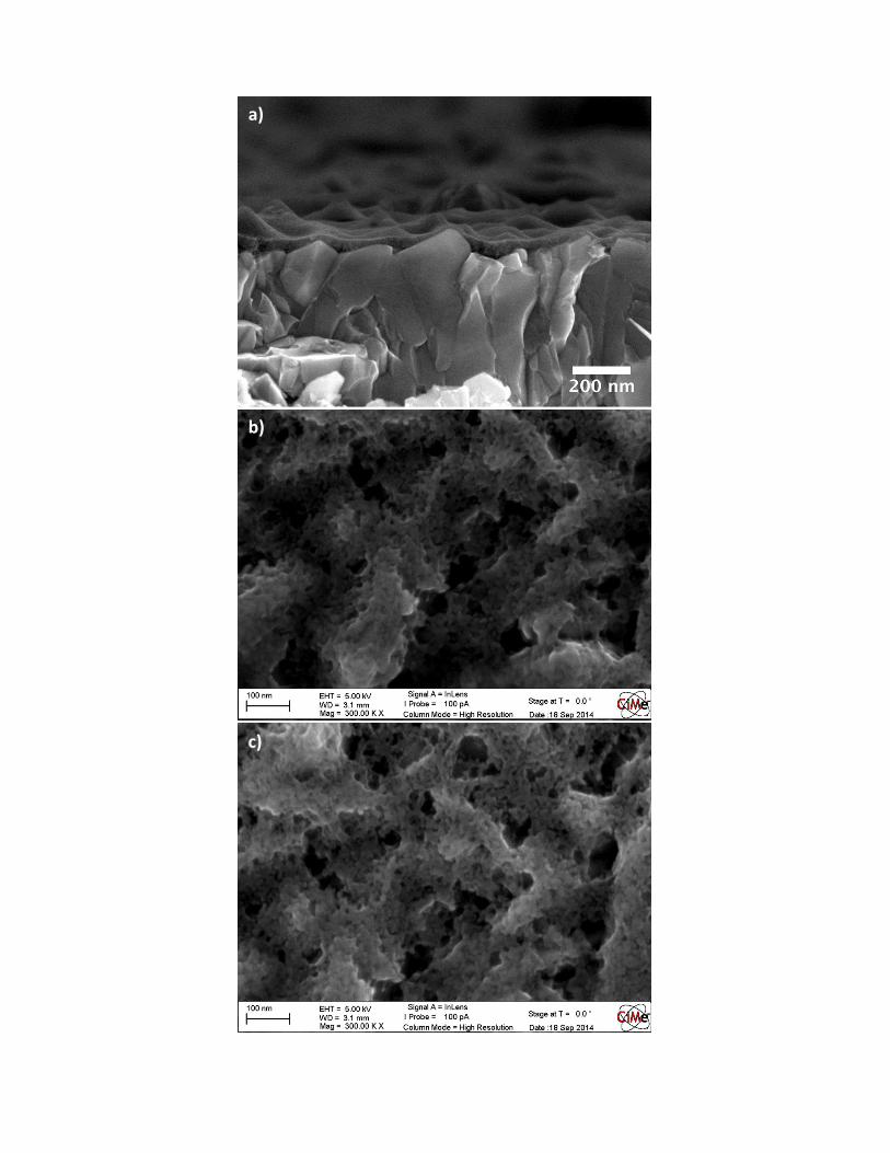
a)
Figure SI1. SEMs of a spray pyrolized BL: a) and b) show cross sections of the compact TiO2 on FTO
b)
a)
b)
c)
d)
e)
f)
Figure SI2. SEMs of spin coated BL a) Cross section and b) to g) top view with different magnifications
Table SI1. Oxidation and reduction peak current and the peak to peak separation from the CV measurements
sample Oxidation peak
current ( mA/cm2)
Reduction peak current
( mA/cm2)
Peak to Peak separation
(mV) FTO 1.13 1.11 160
Sprayed BL - - - Spin Coated BL 0.83 0.64 230 PA with 18 NRT 0.76 0.54 560
PA with rutile 0.78 0.66 570
g)
Figure SI3. Nyquist plots of the FTO electrode (black), of the FTO with spin coated BL (blue), of the FTO with spray pyrolised BL (red), the PA with 18 NRT particles (green) and the PA with rutile
particles (magenta) at 288 mV vs Ag/AgCl (sat.). Inset shows the Randles circuit used for the fitting procedure.
Rserie R2 Wo2
CPE2
Figure SI4. a) Modulus of the DC current during the EIS measurement (bare FTO substrate (black), FTO with a spin coated (blue) and FTO with spray coated (red) BL on top. Green represents a complete photoanode with 18 NRT particles and magenta the PA with rutile particles as mesoporous scaffold (see text)). b) Charge transfer resistance determined from the impedance measurements. c) Capacitance determined from the impedance measurement. All measurements are performed in 0.5 M KCl (pH=2.5) solution with 5 mM [Fe(CN)6]
3-/ [Fe(CN)6]4- as the probing redox system (Potential vs.
Ag/AgCl (sat.)).
a) b)
c)
Figure SI5. Dark (black) and photocurrent (blue) of a device without any kind of BL with the rutile
particles. Inset shows the logarithm of the dark and photocurrent. Measurement was performed with