STRUCTURAL DYNAMIC ANALYSIS OF A RECOVERABLE ORBITAL PLATFORM EXPERIMENTS MODULE Artur C. Arantes Filho (1) , Luis Eduardo V. Loures da Costa (2) (1) IAE - Instituto de Aeronáutica e Espaço / ASE Praça Marechal Eduardo Gomes, 50 - Campus do CTA - Vila das Acácias CEP 12228-904 - São José dos Campos - SP – Brasil. Phone: +55 12 39474615 E-mail: [email protected](2) IAE - Instituto de Aeronáutica e Espaço / ASE Praça Marechal Eduardo Gomes, 50 - Campus do CTA - Vila das Acácias CEP 12228-904 - São José dos Campos - SP – Brasil. Phone: +55 12 39474615 E-mail: [email protected]ABSTRACT The development and structural analysis of an Experiments Module (MEXP) of SARA Suborbital Platform is under development. SARA (Atmospheric Reentry Satellite) is a recoverable platform, which is being designed to perform micro-gravity experiments. The Experiments Module (MEXP) is a Subsystem of SARA whose objective is to properly accommodate the experiments to be performed. The analysis gives an insight to into the structural behavior of MEXP and the accelerations on experiments and equipment. Studies of dynamic and static behavior were conducted and the aim of this paper is twofold (i) demonstrate the failure modes of the composite structure subjected to the static load and, (ii) present the dynamic response of the structure which includes the normal modes, harmonic excitation, random analysis and rocket stage separation shock. The analysis was accomplished with the Finite Element Method by means of Femap/NASTRAN and the results show the acceleration levels experienced by the scientific experiments and the Electric Subsystem of SARA. In addition, stresses and strains fields for both composite facesheet and aluminum facesheet sandwich panels are compared. 1. INTRODUCTION Recoverable Orbital platform SARA is being developed to perform microgravity experimental tests. Nevertheless, during it development several subsystem are being studied and ground and flight tests will have to be conducted, so as these subsystem may function property. The flight for the first approach consider the use of a Suborbital rocket that should take the capsule to an altitude of around 360 km, and following a ballistic trajectory it will be recovered with the use of parachutes, on water. SARA is shown in Fig. 1. The Experiments Module (MEXP) is a Subsystem of SARA whose objective is to properly accommodate the experiments to be performed. The MEXP is designed mainly in composite materials [1], allowing a significant reduction of structural mass. This reduction provides not only structural optimization but the possibility of an increase in payload mass. Figure 1: SARA Suborbital 2. EXPERIMENTS MODULE OPTIMIZATION The Experiments Module was originally projected to use three metallic cylinders to accommodate experiments, as shown in Fig. 2. The new MEXP was designed to reduce the systems mass. In order to achieve this goal, the new concept uses mainly composite materials, allowing a significant reduction of structural mass. In the frame of the optimization of composite structures, the numerical approach is implemented through the finite element method (FEM), where different solutions were applied for the new MEXP conception. These numerical solutions through the FEA of new MEXP provide 83% reduction of structural mass in comparison to the metallic cylindrical option. This second MEXP version is also shown in Fig. 2. Figure 2: MEXP version 1 and MEXP version 2 ___________________________________________________________________________________ Proc. ‘19th ESA Symposium on European Rocket and Balloon Programmes and Related Research, Bad Reichenhall, Germany, 7–11 June 2009 (ESA SP-671, September 2009)
Transcript
STRUCTURAL DYNAMIC ANALYSIS OF A RECOVERABLE ORBITAL PLATFORM EXPERIMENTS MODULE
Artur C. Arantes Filho(1), Luis Eduardo V. Loures da Costa(2)
(1) IAE - Instituto de Aeronáutica e Espaço / ASE Praça Marechal Eduardo Gomes, 50 - Campus do CTA - Vila das Acácias
CEP 12228-904 - São José dos Campos - SP – Brasil. Phone: +55 12 39474615 E-mail: [email protected]
(2) IAE - Instituto de Aeronáutica e Espaço / ASE
Praça Marechal Eduardo Gomes, 50 - Campus do CTA - Vila das Acácias CEP 12228-904 - São José dos Campos - SP – Brasil. Phone: +55 12 39474615
The development and structural analysis of an Experiments Module (MEXP) of SARA Suborbital Platform is under development. SARA (Atmospheric Reentry Satellite) is a recoverable platform, which is being designed to perform micro-gravity experiments. The Experiments Module (MEXP) is a Subsystem of SARA whose objective is to properly accommodate the experiments to be performed. The analysis gives an insight to into the structural behavior of MEXP and the accelerations on experiments and equipment. Studies of dynamic and static behavior were conducted and the aim of this paper is twofold (i) demonstrate the failure modes of the composite structure subjected to the static load and, (ii) present the dynamic response of the structure which includes the normal modes, harmonic excitation, random analysis and rocket stage separation shock. The analysis was accomplished with the Finite Element Method by means of Femap/NASTRAN and the results show the acceleration levels experienced by the scientific experiments and the Electric Subsystem of SARA. In addition, stresses and strains fields for both composite facesheet and aluminum facesheet sandwich panels are compared.
1. INTRODUCTION
Recoverable Orbital platform SARA is being developed to perform microgravity experimental tests. Nevertheless, during it development several subsystem are being studied and ground and flight tests will have to be conducted, so as these subsystem may function property. The flight for the first approach consider the use of a Suborbital rocket that should take the capsule to an altitude of around 360 km, and following a ballistic trajectory it will be recovered with the use of parachutes, on water. SARA is shown in Fig. 1.
The Experiments Module (MEXP) is a Subsystem of SARA whose objective is to properly accommodate the experiments to be performed. The MEXP is designed mainly in composite materials [1],
allowing a significant reduction of structural mass. This reduction provides not only structural optimization but the possibility of an increase in payload mass.
Figure 1: SARA Suborbital 2. EXPERIMENTS MODULE OPTIMIZATION
The Experiments Module was originally projected to use three metallic cylinders to accommodate experiments, as shown in Fig. 2.
The new MEXP was designed to reduce the systems mass. In order to achieve this goal, the new concept uses mainly composite materials, allowing a significant reduction of structural mass. In the frame of the optimization of composite structures, the numerical approach is implemented through the finite element method (FEM), where different solutions were applied for the new MEXP conception.
These numerical solutions through the FEA of new MEXP provide 83% reduction of structural mass in comparison to the metallic cylindrical option. This second MEXP version is also shown in Fig. 2.
Figure 2: MEXP version 1 and MEXP version 2
___________________________________________________________________________________ Proc. ‘19th ESA Symposium on European Rocket and Balloon Programmes and Related Research, Bad Reichenhall, Germany, 7–11 June 2009 (ESA SP-671, September 2009)
3. ANALYSIS OBJECTIVE
Analyses performed with the Finite Element Method show failure modes for static and dynamic loads.
4. SIMPLIFIED MATHEMATICAL MODEL
NASTRAN analyses apply complex mathematical solutions and demand much time to obtain reliable results. Equations used by NASTRAN to solve the structural analysis are shown below [2].
For the static analysis, the simplified mathematical model is:
{ } [ ]{ }xKF = , (1)
where [K] is the stiffness matrix, {F} is the forcing vector and {x} is the unknown displacement vector.
Modal Analysis considers n degree of freedom
system, whose equation of motion can be expressed in matrix form as:
[ ]{ } [ ]{ } 0=+ xkxm && , (2)
where [M] and [K] are the mass matrix and stiffness matrices respectively, {x&& } is the acceleration vector and {x} is the unknown displacement vector.
Forced vibration is considered for harmonic
excitation and random analysis, with the addition of the external force and damping term in equation (2). Further, if the frequency of excitation (periodic and non periodic force) is at or near one of the natural frequencies of the system, damping is of primary importance and must be taken into account [2][3].
The damped equation of motion for a multidegree freedom system, in matrix form, is:
[ ]{ } [ ]{ } [ ]{ } [ ]Fxkxcxm =++ &&& , (3)
where [C] is the damping matrix and {x& } is the velocity vector.
If vibrational response characteristics such as displacements, accelerations and stresses are known precisely as functions of time, the vibration is known as deterministic vibration. This implies a deterministic system (or structure) and a deterministic loading (or excitation); deterministic vibration exist only if there is perfect control practice. However, there are many processes and phenomena whose parameters can not be precisely predicted. Such processes are therefore called random processes [4].
The most commonly used distribution for modeling physical random process is called the Gaussian or normal random process. The Gaussian process has a
number of remarkable properties that permit the computation of the random vibration characteristics in a simple manner [2]. The probability y(t) lying in the interval -λσ and +λσ is given by:
πσπσλσλσ
σλσ
λσσ
22
1))((
22
22/
2/y
y edxetyP
−
−
− ==≤≤− ∫ , (4)
where λ=1 gives results with 1σ precision, i.e., 68.3%; if λ=2, result one 2σ precision, i.e., 95.4%, and if λ=3 the precision is 3σ i.e., 99.7%. Since the value utilized for λ in this work is λ=3, thus all RMS stress values were multiplied by 3 (3σ / 99.7%).
5. THE FAILURE CRITERION
Tsai Hill failure criterion was applied for carbon/epoxy composites. Von Mises was used for aluminum and, for honeycomb, it was applied a NASA approach for structural stability analysis of sandwich plates and shells [5].
The deviatoric or distortional energy has been proposed by many investigators in various forms as a failure criterion for isotropic ductile metals. For a two dimensional state of stress referred to the principal stress directions, the von Mises yield criterion has the form:
221
22
21 ypσσσσσ =−+ (5)
Where ypσ is the yield stress.
Hill modified this criterion for the case of ductile metals with anisotropy and proposed the following form:
12621
22
21 =+−+ τσσσσ DCBA (6)
Where A, B, C and D are material parameters
characteristic of the current state of anisotropy. Azzi and Tsai adapted this criterion to orthotropic
composite materials of a unidirectional [6]. The parameters of equation (6) can be related to the basic strength parameters of the lamina by conducting imaginary elementary experiments.
2
1
1F
A = 2
2
1F
B = 2
1
1F
C = 2
6
1F
D = (7)
Substituting the values of the parameters A, B, C
and D into equation (6) obtain the Tsai-Hill criterion [7], which includes interactions between stress components and quadratic interaction among them. The Tsai-Hill criterion is inadequate for materials with different tension/compression behavior.
12
1
212
6
26
22
22
21
21 =−++
FFFF
σστσσ (8)
6. FINITE ELEMENT MODEL
The finite element model used the NASTRAN solver for the structural assessment where the displacements, internal loads and dynamic analysis are derived [8].
Materials used for the analyses are aluminum, carbon/epoxy and sandwich (honeycomb) plates with aluminum facesheet and aluminum core, which also allow proper placement ant attachment for the experiments. In the second approach analysis the facesheet was changed by carbon/epoxy with the same thickness.
The Finite Element model is shown in Fig. 3.
Figure 3:Finite Element Model MEXP The finite element model uses shell configuration
with four node isoparametric flat element (CQUAD4), eight node isoparametric quadrilateral curved thick shell element (CQUAD8), where the quadrilateral “flat” shell element may be defined by four grid points with higher refinement where needed (on regions of interest) [8]. The sandwich panels designed for the majority of the structure components were represented by plate (PSHELL/Laminate) elements. For equipments, the mass was introduced at the CG position by a CONM2 and RBE2 elements, for an easy assessment of the load transferred between the structure components [9]. The model described herein used CBAR elements to link the Angle Bar plates, which were modeled with CQUAD8 elements, as shown in Fig. 4. In order to get the corresponding nodes at each fastener position, the nodes were offset 1mm and a bar was placed between them [10].
Angle Bar displaced for clarity
Figure 4: Angle Bar FEM detail
Figure 5: Angle Bar CAD detail Figure 5 shows the CAD model of Angle Bar
plates. Sets of boundary conditions were introduced into
the FEM model and constraint set was placed at the plate base as SPC123456 intended to simulate the constraint placed by the SARA system. 7. LOAD CASES
The flight static loads [11] applied on the analysis were:
Table 1: Flight Static Loads
Case Type Value Applied
Axial (axis Y)
Applied Lateral (axis X)
Applied Lateral (axis Z)
1 Acc 43,17 m/s² ●
2 Acc 43,17 m/s² ●
3 Acc 129,5 m/s² ●
4 Acc -129,5 m/s² ●
5 Spin 2,3 Hz ●
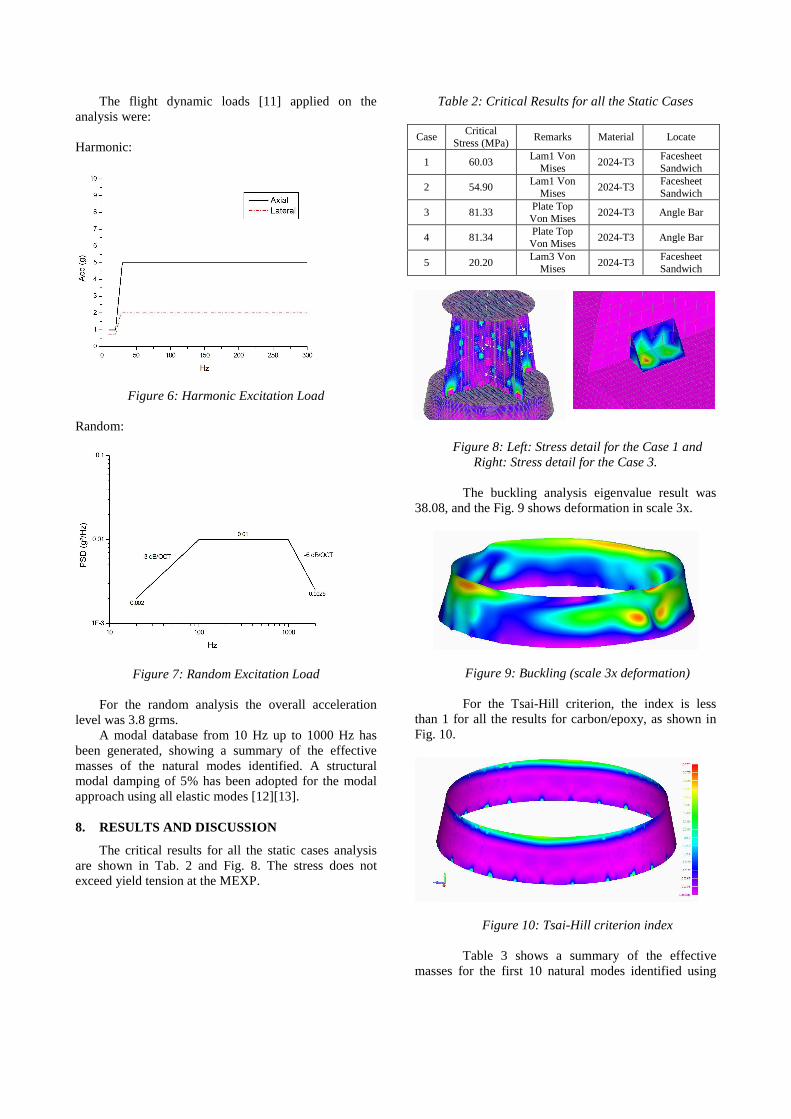
The flight dynamic loads [11] applied on the analysis were: Harmonic:
Figure 6: Harmonic Excitation Load Random:
Figure 7: Random Excitation Load
For the random analysis the overall acceleration level was 3.8 grms.
A modal database from 10 Hz up to 1000 Hz has been generated, showing a summary of the effective masses of the natural modes identified. A structural modal damping of 5% has been adopted for the modal approach using all elastic modes [12][13].
8. RESULTS AND DISCUSSION
The critical results for all the static cases analysis are shown in Tab. 2 and Fig. 8. The stress does not exceed yield tension at the MEXP.
Table 2: Critical Results for all the Static Cases
Case Critical
Stress (MPa) Remarks Material Locate
1 60.03 Lam1 Von
Mises 2024-T3
Facesheet Sandwich
2 54.90 Lam1 Von
Mises 2024-T3
Facesheet Sandwich
3 81.33 Plate Top Von Mises
2024-T3 Angle Bar
4 81.34 Plate Top Von Mises
2024-T3 Angle Bar
5 20.20 Lam3 Von
Mises 2024-T3
Facesheet Sandwich
Figure 8: Left: Stress detail for the Case 1 and
Right: Stress detail for the Case 3. The buckling analysis eigenvalue result was
38.08, and the Fig. 9 shows deformation in scale 3x.
Figure 9: Buckling (scale 3x deformation)
For the Tsai-Hill criterion, the index is less than 1 for all the results for carbon/epoxy, as shown in Fig. 10.
Figure 10: Tsai-Hill criterion index
Table 3 shows a summary of the effective masses for the first 10 natural modes identified using
aluminum facesheet sandwich, for which the 7th mode is important for the Y longitudinal panel mode MEXP direction [14].
Stress resultants for aluminum facesheet, under harmonic and random loads are shown in Tab. 4. Stresses exceed the material yield stress on the Angle Bar plates, which, probably due to the 7th mode low stiffness. Based on the results, further investigations were carried out to evaluate the effect of the 7th mode influence on the Y longitudinal direction.
Table 4: Critical Results for all the Dynamic Cases
using aluminium facesheet sandwich
Case Critical Stress
Remarks Material Locate
Harmonic 343 MPa Plate Top Y
Normal Stress
2024-T3 Angle Bar
Random 455 MPa Plate Bot X Stress RMS
2024-T3 Angle Bar
Figure 12 shows the critical longitudinal mode results with harmonic acceleration on node 14036. It is clearly noted the peak at 73.90 Hz (resonance). The node location is on the MEXP panel.
Figure 12: Acceleration on Panel (Note the peak at 73.90 Hz – 7th normal mode)
For the second approach the sandwiches were
modified with carbon/epoxy facesheet [15]. Table 5 shows the new normal modes for MEXP. Further Tab. 6 shows the results for the critical stress on the Angle Bar plates.
Table 6: Critical Results for all the Dynamic Cases
using composite facesheet sandwich
Case Critical Stress
Remarks Material Locate
Harmonic 195 MPa Plate Top Y
Normal Stress 2024-T3
Angle Bar
Random 166 MPa Plate Top X Stress RMS
2024-T3 Angle Bar
It can be seen from Tab. 6 that a significant
reduction in stress on Angle Bar plates is possible with only slight higher natural frequencies, due the change of the materials facesheets.
Acceleration levels are obtained for all the equipments and experiments of MEXP. These
accelerations are below the limit of Electric Subsystem SARA specifications. Figures 13 and 14, shown acceleration.
Figure 13: Acceleration on Experiments (Example for only one experiment)
Figure 14: Acceleration on Equipment (Example for only one equipment)
Masses for both approaches are given Tab. 7.
The slight difference is important for reduced influence on the system’s natural frequencies.
Table 7: Masses of the two approaches for MEXP
Approach 1
Aluminum facesheet Approach 2
Composite facesheet Mass (kg) 5.76 5.73
9. CONCLUSIONS
The development and optimization of
structures using the finite element method shows that this technique is important to identify problems on structural behaviour in the preliminary design phase [16]. The paper shows an increase in panels natural frequencies using composite facesheets sandwiches compared to aluminium facesheets. The change does not significantly affect the MEXP mass, and reduces the stress on the Angle Bar plates.
The low natural frequencies influence considerably the high structural stress values. Thus, the use of composite materials is important in increase
structural stiffness (rigidity) in Y direction mainly, which was the choice for this project.
The analysis herein described also emphasizes the importance of the random and harmonic loads on identifying the critical stress on the structure. It also shows that the acceleration on the equipaments are far below the allowable limits for SARA’s Electric Subsystem. 10. ACKNOWLEDGMENTS
We would like to thank PhD José Guido Damilano and M.Sc Lizia Oliveira Acosta Dias for giving us lessons about finite element method and all support during this analysis. We thank Maj. Eng. José Antonio Azevedo Duarte for offering clarification regarding structural dynamic analysis. 11. REFERENCES
1.Isaac M. Daniel, et al., Engineering Mechanics of Composite Materials, Oxford University Press, Inc.
2.Singiresu S. Rao, Mechanical Vibration, Second Edition, Addison-Wesley Publishing Company.
3.Andrew Dimarogonas, Vibration for Engineers, Prentice Hall.
4.Robert D. Cook, Finite Element Modeling for Stress Analysis, John Wiley & Sons, Inc.
5.NASA, Structural Stability Analysis of Sandwich Plates and Shells, NASA Technical Report.
6. Tsai, S. W., Theory of Composites Design. 7. Daniel Gay, Matériaux Composites, Hermès. 8.Harry G. Shaeffer, MSC/NASTRAN Primer Static and
Normal Modes Analysis, Schaeffer Analysis, Inc. 9.José J. Granda, et al., Alternative Techniques for
Developing Dynamic Analysis Computer Models of The International Space Station, Space Shuttle and Orbiter Repair Maneuvers, AIAA 2006-2103.
10.NASA, Criteria for Preloaded Bolts, NASA Technical Report.
11.Artur C. Arantes Filho, Estimativa das Cargas Dinâmicas para o Projeto VS40/SARA Suborbital, IAE Technical Report.
12.Maher N. Bismarck, Structural Dynamics in Aeronatutical Engineering, AIAA Series.
13.Leonard Meirovitch, Analytical Methods in Vibration, The Macmillan Company.
14.Artur C. Arantes Filho, Análise Estrutural do Módulo de Experimentação do SARA Suborbital, IAE Technical Report.
15.Salvatore Liguore, et al., Prediction and Measurement of Structural Loss Factors in Damped Composite Panels under Pressure Loads, AIAA 2008-2236.
16.ECSS, Space Engineering Mechanical, ECSS Requirements Report.
17.Eric R. Christensen, et al., Calculation of Dynamic Loads due to Random Vibration Environments in Rocket Engine Systems, AIAA 2007-1784.