1
MME 6203, Lecture 02
Structure, Defects and Properties of Finished Castings1. Oxide film, bubble damage and shrinkage problem
Summary of casting defects
Oxide film and bubble trail defects
Shrinkage porosity
Today’s Topics...
2
Oxide films and bubble trails Segregation, inclusion and gas porosity Shrinkage cavity Hot tear and cold crack Residual stress
1. Summary of Casting Defects
2. Oxide Film and Bubble Trail
Some liquid metals may be really like liquid metals.• e.g., pure liquid gold, C-Mn steels at a late stage of melting
These, however, are rare.• many liquid metals are actually so full of sundry solid phase floating about,
that they actually closely resemble slurries than liquids.
• e.g., inclusions from charge, refractory lining; reaction products, etc.
Many of the strength related properties of liquid metal can only be explained by assuming that the melt is full of defects.classical physical metallurgy or solidification science (which consider metals as
merely pure metals) unable to explain important properties of cast materials such as the effects of DAS, and existence of pores and their area density
3
2.1 Reactions of the melt with its environment
[a] Pick up of moisture from damp refractories
M + H2O = MO + H2
H2 = 2[H]
[b] Reaction involving hydrocarbon fuels
CH4 + 2O2 = CO2 + 2H2O
M + H2O = MO + H2
H2 = 2[H]
Reactions products 1. dissolve rapidly in the metal, and diffuse away into its interior
2. those unable to diffuse escape into the atmosphere
3. remain on the surface as films
[H]2 = k pH2
the equilibrium gas pressure of a melt
applies both to the external and internal
environments of the melt.
4
Oxide films usually start as simple amorphous layers, which quickly convert to crystalline products as they thicken, and later often develop into a bewildering complexity of different phases and structures.
• Some films remain thin, some grow thick.
• Some are strong, some are weak.
• Some grow slowly, others quickly.
• Some are heterogeneous and complex in the structure, being lumpy mixtures of different phases.
M + H2O = MO + 2[H]
CxHy = xC + y[H]
1. Formation of oxide film by decomposition of moisture
2. Formation of graphite film by decomposition of hydrocarbon
Two film-forming reactions:
A film is not harmful when it remains on top of the surface• in case of aluminium, the surface film protects the liquid from catastrophic
oxidation (as in the case with Mg)
The problem with a surface film only occurs when it becomes a submerged film
• In conditions for the formation of a transient film, if the surface happens to be entrained by folding over, although the film is continuously dissolving, it may survive sufficiently long to create a legacy of permanent problems.
• These could include the initiation of porosity, tearing or cracking, prior to its complete disappearance.
Entrained films form the major defect in cast materials.
5
2.2 Entrainment
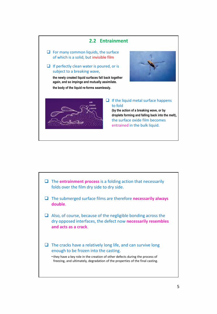
For many common liquids, the surface of which is a solid, but invisible film
If the liquid metal surface happens to fold (by the action of a breaking wave, or by
droplets forming and falling back into the melt), the surface oxide film becomes entrained in the bulk liquid.
If perfectly clean water is poured, or is subject to a breaking wave,
the newly created liquid surfaces fall back together
again, and so impinge and mutually assimilate.
the body of the liquid re-forms seamlessly.
The entrainment process is a folding action that necessarily folds over the film dry side to dry side.
The submerged surface films are therefore necessarily always double.
Also, of course, because of the negligible bonding across the dry opposed interfaces, the defect now necessarily resembles and acts as a crack.
The cracks have a relatively long life, and can survive long enough to be frozen into the casting. • they have a key role in the creation of other defects during the process of
freezing, and ultimately, degradation of the properties of the final casting.
6
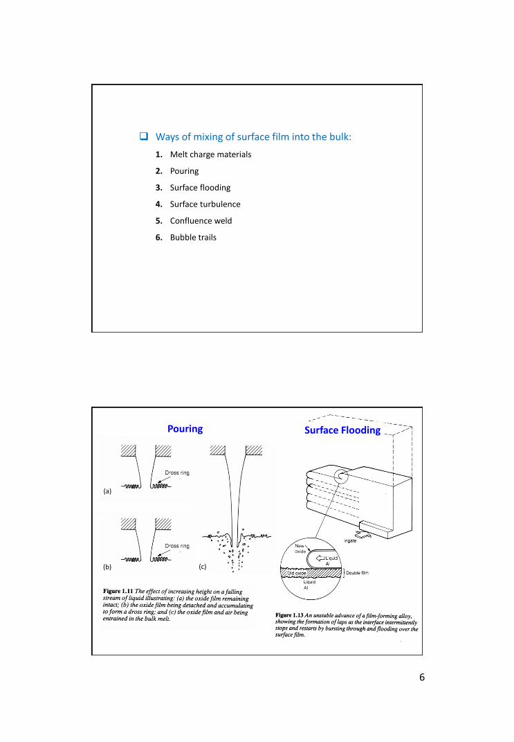
Ways of mixing of surface film into the bulk:
1. Melt charge materials
2. Pouring
3. Surface flooding
4. Surface turbulence
5. Confluence weld
6. Bubble trails
(a)
(b) (c)
Pouring Surface Flooding
7
V = velocity of melt r = density of melt
d = linear dimension of flow path n = viscosity of melt
r = radius of curvature of film g = surface tension
Re = Vrd / n
Re < 2000, smooth, laminar, turbulent-free flow
Re > 2000, turbulent flow
Reynolds number :
Weber number : We = V2rr / g
We = 0.2 – 0.8, free from surface turbulence
We = 100, surface turbulence becomes problematic
We = 100000, creates atomization !!
Measures bulk turbulence
Measures surface turbulence
Surface Turbulence
(a)
(b)
(c)
Confluence Weld
8
Bubble Trails
2.3 Entrainment defects
Figure 2.4 Entrainment defects:
(a) a new biflm;
(b) bubbles entrained as an integral part of bifilm;
(c) liquid flux trapped in a biflm;
(d) surface debris entrained with the biflm;
(e) sand inclusions entrained in the bifilm;
(f) an entrained old film containing integral debris
• If the entrained surface is a solid film the resulting defect is a crack.
• It may be only a few nanometresthick, and so be invisible to most inspection techniques.
• In the case of the folding-in of a solid film on the surface of the liquid the defect will be called a bifilm (i.e., a double film defect).
9
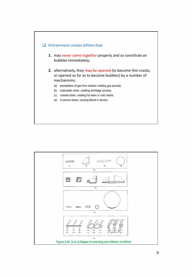
Entrainment creates bifilms that:
1. may never come together properly and so constitute air bubbles immediately;
2. alternatively, they may be opened (to become thin cracks, or opened so far as to become bubbles) by a number of mechanisms:(a) precipitation of gas from solution creating gas porosity;
(b) hydrostatic strain, creating shrinkage porosity;
(c) uniaxial strain, creating hot tears or cold cracks;
(d) in-service stress, causing failure in service.
Figure 2.40 (a to d) Stages of unfurling and inflation of bifilms
11
2.4 Significance of bifilm
Submerged bifilms are always associated with air or other gas, trapped on the non-wetted dry surface of the film, or trapped between the folded film.
• The gaseous films floated around the liquid constitute
cracks in the liquid and, after freezing, constitute cracks in
the finished products.
• The gas-coated film acts as excellent nucleating sites for
the subsequent growth of bubbles or shrinkage cavity.
• Higher-melting-point heavy phases may be precipitated on
to the floating oxides, which form defects with large, coarse
crystals of heavy intermetallic phase, together with
entrained oxide film and associated porosity.
General problem due to submerged bifilms
12
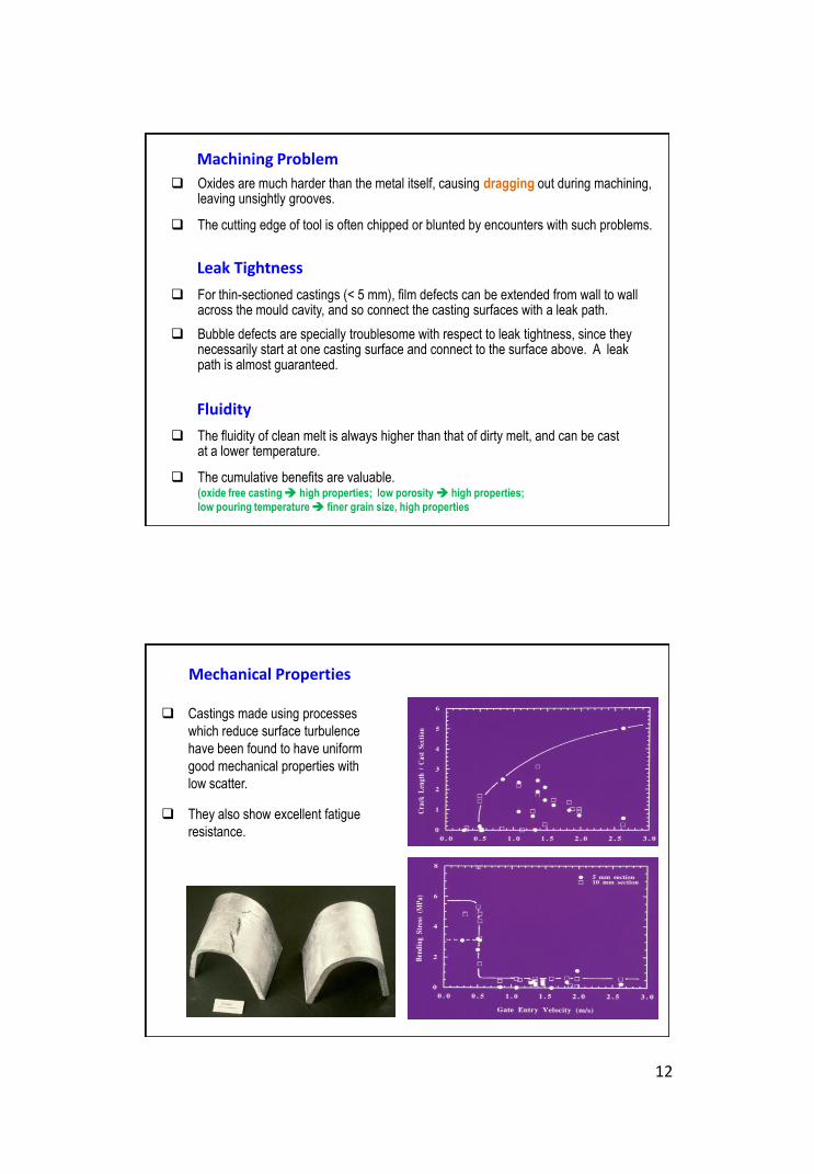
Oxides are much harder than the metal itself, causing dragging out during machining, leaving unsightly grooves.
The cutting edge of tool is often chipped or blunted by encounters with such problems.
Machining Problem
For thin-sectioned castings (< 5 mm), film defects can be extended from wall to wall across the mould cavity, and so connect the casting surfaces with a leak path.
Bubble defects are specially troublesome with respect to leak tightness, since they necessarily start at one casting surface and connect to the surface above. A leak path is almost guaranteed.
Leak Tightness
The fluidity of clean melt is always higher than that of dirty melt, and can be cast at a lower temperature.
The cumulative benefits are valuable. (oxide free casting high properties; low porosity high properties;
low pouring temperature finer grain size, high properties
Fluidity
Castings made using processes
which reduce surface turbulence
have been found to have uniform
good mechanical properties with
low scatter.
They also show excellent fatigue
resistance.
Mechanical Properties
13
Al-4.5Cu fractured surfaces(a) Oxide covered (0.3 % elongation)(b) Ductile fracture (3.0 % elongation)
Liquid contracts on freezing because
of rearrangement of atoms from
open “randomly-packed” structure to
a regular “densely-packed” structure.
FCC and HCP solids contract
more during solidification.
What happens to
a poorly fed casting?
3. Shrinkage Defects
3.1 General Shrinkage Behaviour
14
R0
R
dx
X
Liquid
Feed Liquid
Solid
Solidification model for an unfed sphere
A sphere has been fed via an ingate
of negligible size and the source of
feed metal is cut off after a solid shell
of thickness X is produced.
What will happen during solidification of
the next onion-layer of thickness dx ?
Either a pore will form or the liquid will expand a little to compensate the
volume difference.
If no favourable nucleus available for pore formation, the liquid has to
accommodate this by expansion, creating a state of tension or negative
pressure and sucking the solid shell inwards.
Whether the driving force for pore formation wins over the
driving force for feeding will depend on whether nuclei for pore
formation exist.
If not (i.e. the metal is clean), then pore will not be able to
nucleate and feeding is forced to continue until the casting is
completely frozen.
If favourable nuclei are present, then pores will be created at an
early stage before the development of any significant
hydrostatic pressure, with the result that little feeding will occur
and the casting will develop its full percentage of porosity as
defined by the physics of phase change.
15
In most practical cases, the situation is somewhere between
these two extremes, with castings displaying some internal
porosity, together with some liquid feeding.
In such cases feeding has continued under increasing pressure
differences, until the development of a critical internal stress at
which some particular nuclei, or surface puncture, can be
activated at one or more points in the casting. Feeding is then
stopped at such locality, and pore growth starts.
When pores appear early
diameter of shrinkage cavity formed
in 100 mm dia sphere casting
31 mm
41 mm
Theses considerable cavities require a dedicated effort to ensure that
they do not appear in castings.
There are occasions when castings having defects of only 1 or 2 mm
in size are scrapped!!
For vast majority of cast materials, therefore, shrinkage porosity
is the most common and most important defect in castings.
freezing contraction
Steel 3 vol.%
Aluminium 7 vol.%
16
1. Heat transfer requirement
2. Volume requirement
3. Junction requirement
4. Feed path requirement
5. Pressure differential requirement
6. Pressure requirement
3.2 Feeding – the Six Rules
The gradual formation and growth of dendritic mass of solids
during solidification presents increasing difficulties for the passage
of feeding liquids.
During solidification, the pressure inside liquid also falls, causing
and increased pressure difference between the inside and outside
of the casting.
Such negative pressure difference is undesirable in casting because it
causes problems by providing the driving force for the initiation and growth of
volume defects such as porosity.
3.3 Feeding Mechanisms
17
Schematic representation of the five feeding
mechanisms in a solidifying casting
There appears to be at least five mechanisms by which such
pressure difference (and the hydrostatic tension caused by it)
can be reduced in solidifying material.
1. Liquid feeding
2. Mass feeding
3. Interdendritic feeding
4. Burst feeding
5. Solid feeding
Liquid feeding
Generally precedes other forms of feeding.
For skin-freezing materials, this is the only method of feeding.
Occurs at the early stage of solidification
Wide feed path due to low liquid viscosity, and the pressure difference required
to continue feeding is negligibly small (~ 1 Pa).
When about 99 % solidification is completed, the pressure could reach up to
about 100 Pa only (1 atm 105 Pa).
For all practical purposes, therefore, the hydrostatic stresses
created during liquid feeding never causes a problem!!
18
Inadequate feeding only resulted when inadequate-sized feeder is
used. Feeding terminates early and air is drawn into the casting.
Two forms of porosity resulted:
Skin-freezing alloys
smooth shrinkage pipe, extending from the feeder into the casting as a
long funnel-shaped hole.
Long-freezing-range alloys
feeding occurs through interdendritic channels
porosity resembles a mass of spongy, interconnecting shrinkage pipes.
Mass feeding
Movement of slurry of solidified metal and residual liquid.
This movement is arrested when the volume fraction of solid
reaches anywhere between 0 and 50 % depending on
Pressure differential that driving the liquid
Amount of free dendrites in the liquid
Role of mass feeding is of minor importance since the critical
stages of feeding which most influence defects occur later after
mass feeding comes to a stop.
Mass feeding period can be extended by grain refinement and
formation of more equiaxed grains.
19
Interdendritic feeding
Feeding of residual liquid through mushy zone.
The pressure gradient required for interdendritic feeding of a
cylindrical area of pasty zone.
h = viscosity of liquid d = dendrite arm spacing
a = solidification shrinkage R = radius of capillary
L = length of past zone D = diam. of pasty zonel = heat-flow constant (rate of freezing)
The pressure difference is the most sensitive to the size of flow
channel, R. DP becomes extremely high as R becomes small.
24
222
DR
dL
-1 32 P
l
a
ahD
In the absence of suitable nuclei for pore formation, the high
hydrostatic pressure is somewhat compensated by the inward collapse
of the solid.
Effect of the presence of eutectic
Eutectics (short-freezing range alloys) solidify in the planer mode.
In presence of eutectic, the interdendritic flow paths do not taper to zero, but finish abruptly trimmed.
20
Burst feeding
As solidification progresses, both hydrostatic stress inside liquid and
strength of feeding barrier increase in a poorly fed region of casting,
but at different rates.
If stress grows at a faster rate, failure of casting is expected.
The internal stress will be reduced to allow the casting to remain free from
shrinkage porosity.
If the barrier is substantial, it may never burst, causing the resulting stress to
rise and eventually exceeds the pore nucleation threshold. The stress is then
released by forming the shrinkage cavity.
If the barrier is only a partial barrier, failure may not occur.
Instead, feeding occurs in a burst when a sudden yield of feeding barrier
occurs due to hydrostatic tension.
Solid feeding
At the later stage of solidification, certain sections of casting may become
isolated from feed liquid.
Further solidification in this isolated region would cause a high hydrostatic
stress in the remaining liquid, high enough to cause the surrounding
solidified shell to deform inwards by plastic or creep flow.
P = 2 Y ln (R0/R)
Stress in liquid developed depends upon the plastic flow of solid that,
in turn, is a function of yield stress and geometry of casting.
For iron sphere of 20 mm in diameter, P can be reached up to -200 to -400
atm when the casting is 99.998 % solid. In the last liquid drops, this can
reach up to -1000 atm !
Y = Yield stress of solid
R0 = Radius of spherical casting
R = Internal liquid radius
21
In absence of gas, and if feeding is adequate, no porosity will be
formed.
For large and/or complex castings, one or more regions of
casting are not well fed and the liquid contains dissolved gasses.
The internal hydrostatic stress reaches to a level when internal pore
can form.
If solid feeding occurs, internal pore will not occur, but the solidification
shrinkage will appear at the surface of the casting.
3.4 Initiation of Shrinkage Porosity
22
Internal porosity by surface initiation
If the liquid is connected to the outside surface, then the liquid
can be sucked in, causing the porosity to form connected to the
surface.
The sucking of liquid from surface also draws air which flows
along the interdendritic channel causing air feeding (as opposed
to liquid feeding) into the casting.
The porosity formed in this way is indistinguishable from
microporosity.
• This pore-forming mechanism is
common in long freezing range
alloys at a later stage of
solidification, initiated often from a
hot spot .
• Sometimes these pores can connect
internally two opposite surfaces of
thin casting causing these alloy
castings unsuitable for pressure-tight
applications.
• A high enough positive internal
pressure is necessary at all locations
to prevent initiation of this type of
surface-connected internal porosity.
In thin-section castings, little or no feeding is necessary and sucking
of surface liquid is negligible.
For intermediate thickness, surface initiated pores can occur
because of interdendritic feeding problems.
23
Internal porosity by nucleation
Short-freezing range alloys do not exhibit surface-connected
porosity. A sound, solid skin is formed at the early stage of
solidification. Feeding is not a problem at this stage.
At the end of freezing, pores are nucleated in the interior of liquid
due to poor feeding which have no connection with the outside
surface of casting.
After nucleation, further solidification results growth of these pores.
These “centreline porosity” are concentrated near the centre of the
casting and do not impair the leak-tightness of the casting.
In presence of surface-activated foreign particles, nucleating of
these pores is not a problem.
In absence of such particles, nucleation only occurs when the
internal pressure accumulates and reaches to a certain threshold
value, Pf , called the fracture pressure.
Pf = Ps + Pg
2g/r = Pi – Pe = DP (condition for pore formation)
2g/r* = Pg – (-Ps) = Pf (for pore of critical size)
The gas pressure, Pg , inside the liquid will join the negative pressure,
Ps , to push the liquid away for the nucleation of the pore.
24
For well-fed castings with dissolved gases, Ps = 0.
Freezing will proceed along the line ADCE.
Gas pore will form heterogeneously at E on nucleus 1.
Gas pressure goes back towards D.
For poorly fed casting having no dissolved gases, Pg = 0.
Internal pressure falls along the line AF.
At F, fracture pressure for heterogeneous nucleation on nucleus 1 is met, and a shrinkage cavity forms.
The hydrostatic tension is released and pressure returns to A.
In practice, both gas and shrinkage will be present to some
degree, and the freezing will progressed along the line
ABCD. Both porosity and cavity will form.
External porosity
If internal porosity is not formed, then the surface will “sink” due to
solid feeding.
Adequate positive internal pressure would reduce or eliminate solid
feeding and the casting would be sound and maintain its shape.
Too high an internal pressure would reverse the movement of the
surface and make the casting “swell”.
Examples: GCI, castings having high head of metal.
25
The internal pores nucleated within a stressed liquid grow
explosively fast at the beginning.
The subsequent growth of pore occurs leisurely and is controlled by
the rate of solidification i.e., the rate of heat extraction.
For surface-initiated pores, the rate is slow since the initial stress is
lower and the puncture of surface will occur relatively slowly as the
surface collapses plastically into the forming hole.
When pore formed as shrinkage pipe, the growth is progressive and
controlled by the rate of heat extraction from the casting.
3.4 Growth of Shrinkage Porosity
Shrinkage cavity or pipe
The secondary shrinkage cavities are only an extension of the primary pipe.
When shrinkage problem occurs in
an isolated region inside the casting:
• For short-freezing-range alloys,
shrinkage pipe would occur. The shape
of this pipe is similar to those occur in
case of liquid feeding.
• For long-freezing range alloys, layer
porosity is formed in an isolated region
inside the casting.
During liquid feeding, the solidification
front progresses gradually towards
the centre of the casting. The liquid
level in the feeder falls gradually, thus
generating a smooth conical funnel
shaped shrinkage pipe.
3.5 Final Form of Shrinkage Porosity
26
Layer porosity
Usually observed in all types of casting alloys.
Conditions favourable for nucleation of layer porosity:
long pasty zone
poor temperature gradient
alloys with high thermal conductivity
moulds with low rate of heat extraction
Initially layer porosity is believed to be caused by the same mechanism
that causes hot tear.
Presently, its formation can be explain by the equations that governs the
interdendritic feeding mechanism:
a
aD
2
xLx
R
1
dt
dR
1N
16 P
23
24
222
DR
dL
-1 32 P
l
a
ahD
The hydrostatic tension increases parabolically
with distance x though the pasty zone of length L.
The stress continues to increase parabolically with
advancing solidification.
Local stress exceeds the threshold value and a pore will
form.
The pore will spread immediately along the isobaric
surface and form a layer.
Local stress will dissipate instantly.
The maximum stress will be at the centre of the remaining
liquid and amounting about 1/4th of the original.
Stress once again will increase with time and second layer
of porosity will form.
Further nucleation and growth events will produce
successive layers until the whole casting is solidified.
The final state consists of layers of porosity with
considerable interlinking.
27
So it is clear that centreline porosity, layer porosity, and dispersed
porosity transform imperceptibly from one to the other.
Also, as the gas content of the alloy is increased, the shrinkage
porosity changed gradually from layer porosity to dispersed
pinhole porosity.
In real castings, the nature of porosity is mixed in nature, allowing
a complete spectrum of possibilities from pure shrinkage layer
type to pure gas-dispersed type.
Next ClassMME 6203, Lecture 03
Structure, Defects and Properties of Finished Castings2. Linear contraction, hot tear and cold crack and residual stresses