26
TELECOMMUNICATIONS STRUCTURED CABLING GUIDELINES AND SPECIFICATIONS University of Chicago IT Services | Infrastructure Services October 2011
| Date post: | 24-Oct-2015 |
| Category: |
Documents |
| Upload: | stefano-squadrani |
| View: | 126 times |
| Download: | 3 times |
TELECOMMUNICATIONS STRUCTURED CABLING GUIDELINES AND SPECIFICATIONS
University of Chicago
IT Services | Infrastructure Services
October 2011
2
University of Chicago Information Technology Services
Telecommunications Structured Cabling 10/1/2011
Guidelines and Specifications
Table of Contents 1 Introduction .................................................................................................................................... 4
1.1 Planning and Design .................................................................................................................... 4
1.2.1 Roles and Responsibilities ......................................................................................................... 5
1.2.2 Communications Infrastructure Budget ................................................................................... 6
2 Horizontal Pathways ....................................................................................................................... 8
2.1 General ......................................................................................................................................... 8
2.2 Information Outlet ...................................................................................................................... 8
2.3 Basket Tray ................................................................................................................................... 9
2.4 J-Hooks ......................................................................................................................................... 9
2.5 Conduit ........................................................................................................................................ 9
2.6 Ceilings ....................................................................................................................................... 10
2.6.1 Plenum ceiling ........................................................................................................................ 10
2.6.2 Drywall ceiling ........................................................................................................................ 10
3 Backbone Distribution ................................................................................................................... 11
3.1 General ...................................................................................................................................... 11
3.2 Entrance Facility ........................................................................................................................ 11
3.3 Main Distribution Frame (MDF) ................................................................................................. 11
3.4 Intermediate Distribution Frame (IDF) ...................................................................................... 11
3.5 Fiber Optic Infrastructure .......................................................................................................... 11
3.6 Copper Infrastructure ................................................................................................................ 11
4 Telecommunication Room Design and Specifications .................................................................. 12
4.1 Main Distribution Frame (MDF) ................................................................................................. 12
4.2.1 Intermediate Distribution Frame (IDF) ................................................................................... 13
5 Fire Stopping ................................................................................................................................. 14
6 Grounding and Bonding ............................................................................................................... 15
7 Labeling Standard ......................................................................................................................... 16
8 Testing and Documentation ......................................................................................................... 18
8.1 General ...................................................................................................................................... 18
8.2 Documentation ......................................................................................................................... 18
9.0 Wireless ..................................................................................................................................... 19
9.1 General ...................................................................................................................................... 19
9.2 Infrastructure Requirements ..................................................................................................... 19
10.0 Security Systems ..................................................................................................................... 20
10.1 Emergency Phones .................................................................................................................. 20
11.0 Classrooms / Conference Rooms ............................................................................................ 21
11.1 General ................................................................................................................................... 21
11.2 Audio Visual ............................................................................................................................ 21
11.3 Wireless .................................................................................................................................. 21
12.0 Diagrams .................................................................................................................................. 22
12.1 Conduit Fill Capacity ................................................................................................................ 22

3
University of Chicago Information Technology Services
Telecommunications Structured Cabling 10/1/2011
Guidelines and Specifications
12.2 Building Grounding and Bonding ............................................................................................ 23
12.3 Equipment Rack Grounding and Bonding ............................................................................... 24
12.4 Sample ITS Main Distribution Frame (MDF) ........................................................................... 25
12.5 Sample ITS Intermediate Distribution Frame.......................................................................... 26

4
University of Chicago Information Technology Services
Telecommunications Structured Cabling 10/1/2011
Guidelines and Specifications
1 Introduction
The University of Chicago and its affiliates depend on a highly robust communications network
infrastructure in order to accomplish the mission of the University. The communications infrastructure
must be able to support all administrative and research functions along with support systems such as Public
Safety and Building Automation. Information Technology Services is responsible for the installation and
maintenance of this communications infrastructure.
Constant change in communications technology drives the specifications within this document. The
communications infrastructure within a building represents a fifteen- to twenty-year investment. Within
that infrastructure life cycle, communications and computing technology will go through several iterations
that will continue to rely on the installed infrastructure. Other factors such as the constant re-programming
of space to meet the changing needs of the University are drivers that require us to build a high quality,
highly flexible infrastructure.
1.1 Planning and Design
This document is published and maintained by Information Technology Services (ITS), and is intended to
serve as a guide for architectural design pertaining to the telecommunications infrastructure at the
University of Chicago. All construction and renovation projects on campus requiring communications
services from ITS must include this document as part of the project‟s scope of work. It contains a complete
description of the University of Chicago‟s Structured Cabling Specifications and Standards. In some cases
these requirements are stated in general terms due to rapid changes in technology. Therefore, ITS staff must
be actively involved in the review of the communications infrastructure design from inception through
construction. ITS infrastructure group must approve all communications designs, drawings and any
modifications to the specifications listed in the Structured Wiring Plan. The Facilities Services Project
Manager shall schedule regular design meetings with an ITS Communications Infrastructure representative,
ITS Network Engineering representative and the business owner(s) representative.
There are several building services that require either voice or data communications. Below is a list of building services that require communications services and need to
be included early on so that a complete list of all the necessary communications locations can be included
in the cost and indicated on the drawings for installation.
Elevators
Building Automation Systems
Fire Alarms
Security (Department of Safety and Security)
o Video surveillance
o Building access
o Emergency Phones
Area of Rescue Assistance
o For details on this contact the University of Chicago‟s ADA/Code Specialist.
Point of Sale Devices (Cash Registers)
Wall phones
5
University of Chicago Information Technology Services
Telecommunications Structured Cabling 10/1/2011
Guidelines and Specifications
1.2.1 Roles and Responsibilities
The project will be responsible for all costs associated with the installation of the telecommunications
infrastructure. This will also including the re-routing of any existing infrastructure necessary to
accommodate the project.
The Project will be responsible for the procurement and installation of the following support infrastructure:
All horizontal pathways including
o Conduit
o Junction boxes
o Drywall rings
o Raceway
o Cable tray
o Pull boxes
o Sleeves
Communications Rooms including
o Power
o Lighting
o HVAC
o Flooring
o Access
Vertical Infrastructure
o Vertical risers
o Vertical pathways
Building Entrance
o Conduit sleeves
o Pathway to MDF
o Outside plant connectivity to existing ITS infrastructure
o Outside plant connectivity for external service providers
ITS will be responsible for procuring:
Material and labor for the installation of all horizontal and vertical communications cable to be
used for connecting to the University‟s voice or data network
Material and labor to build out the support infrastructure in all communications rooms
Material and labor to build out the copper and fiber optic vertical backbone infrastructure
Material and labor to build out the copper and fiber optic building service infrastructure
Material and labor to remove old communications cabling
Material and labor to reroute existing outside plant cable
Material and labor to reroute existing vertical communications infrastructure
ITS will be responsible for managing the telecommunications contractor and any coordination efforts with
the general contractor or their sub contractors. At the conclusion of the project all of the above material and
labor will be billed back to the project by ITS. On large projects, ITS will bill the project on an agreed upon
schedule over the duration of the project. All field changes to the original scope of the project will be
documented and submitted to the Facilities Services Project Manager for approval before any work is done.

6
University of Chicago Information Technology Services
Telecommunications Structured Cabling 10/1/2011
Guidelines and Specifications
1.2.2 Communications Infrastructure Budget
In order for ITS to be able to provide the Facilities Services Project Manager with a gross budget for a
project, ITS will need to involved in the Planning Phase of the project and at minimum we need to have the
following information:
The scope of the project
Project time frame with milestones
Business owner contact information
Access to preliminary drawings
Gross square footage of the building
Number of expected occupants
Types of spaces to be included in the building
Working with the Facilities Services Project Manager, ITS will provide budget estimates for the
communications cabling infrastructure. These costs will include:
Material and installation of the horizontal communications station cable
Material and installation of the support infrastructure in all communications rooms
Material and installation of the copper and fiber optic vertical backbone infrastructure
Material and installation of the copper and fiber optic building service infrastructure
Labor to remove old communications cabling
Material and labor to reroute existing outside plant cable
Material and labor to reroute existing vertical communications infrastructure
The Facilities Services Project Manager will be responsible for estimating the following infrastructure:
All horizontal pathways, including
o Conduit
o Junction boxes
o Drywall rings
o Raceway
o Cable tray
o Pull boxes
o Sleeves
Communications Rooms, including
o Power
o Lighting
o HVAC
o Flooring
o Access
Vertical Infrastructure
o Vertical risers
Building Entrance
o Conduit sleeves
o Pathway to MDF
o Outside plant connectivity to existing ITS infrastructure

7
University of Chicago Information Technology Services
Telecommunications Structured Cabling 10/1/2011
Guidelines and Specifications
All budget figures are subject to change as the project goes through all the design phases. The
communications infrastructure budget should go through no fewer than three (3) reviews during the course
of the project‟s design phases. Working with the Facilities Services Project Manager, ITS will refine
budgetary costs as the project evolves through each of the design phases. Depending on the project, a final
budget should be in place after the 100% Construction Drawings are issued. When ITS receives the 100%
construction drawings an RFP will be sent out to pre-qualified vendors for the installation of the cable
infrastructure and the build out of the communications rooms. The 100% telecommunications drawings
should be completed in accordance with CSI Division 27 specifications. These drawings shall be presented
to ITS in AutoCAD (.dwg) format and will illustrate the following:
All communications locations
All items listed in section 1.1 to accommodate building services
All communications rooms (IDF and MDF)
Cable pathways and risers
Building Entrances
Final room number designations
HVAC systems for all communications rooms
Power in all communications rooms
The telecommunications system herein specified provides for voice, data, video and other University
systems that require data communications (such as the Department of Safety and Security, and Building
Automations Systems) through twisted pair or fiber optic cable. The system shall provide acceptable outlets
for any communications device which requires connection to the University of Chicago‟s network in order
to serve the general needs of the University.
These specifications comply with the following national standards bodies:
ANSI/NFPA 70 National Electrical Code with Indiana Amendments, latest edition
BICSI CO-OSP Customer Owned Outside Plant Manual
BICSI 12th Edition Telecommunications Distribution Methods Manual
BICSI 2nd Edition Customer Owned Outside Plant Design Manual
FCC Rules and Regulations
J-STD-607-A Commercial Building Grounding (Earthing) and Bonding Requirements for
Telecommunications
NFPA 101: Life Safety Code
TIA 568-C Commercial Building Telecommunications Cabling
TIA 569-B Commercial Building Standard for Telecommunications Pathways and Spaces
TIA 758-A Customer Owned Outside Plant Telecommunications Cabling Standard

8
University of Chicago Information Technology Services
Telecommunications Structured Cabling 10/1/2011
Guidelines and Specifications
2 Horizontal Pathways
2.1 General
ITS (Information Technology Services) has adopted a standard that provides a clear and accessible pathway
for all horizontal cable. Horizontal Communications Infrastructure refers to the items that support the voice
and data cable from the information outlet to the IDF. The following is a list of those items starting at the
Information Outlet and terminating in the IDF. Horizontal pathways shall not exceed 270 feet from the
Information Outlet to the IDF.
2.2 Information Outlet
The installation information outlet is mandatory for all new and renovated University buildings in order to
comply with industry standards and to provide the University with a consistent and sustainable
infrastructure.
ITS has chosen Category 6A cable as its standard.
o Commscope Uniprise Ultra 10 10GN4 Category 6A U/UTP, non-plenum, 4 pair cable.
Each information outlet shall have two (2) category 6A cables installed. The first cable shall be a white
cable and the second cable shall be a gray cable.
The work station shall be terminated on Uniprise category 6A 8 position 568B/ RJ45 jacks, gray in
color, and terminated in a two (2) port face plate.
The IDF end will be terminated on a category 6A RJ45 Uniprise patch panel.
All station cable will be secured and dressed with Velcro tywraps
Do not install compressed, kinked, scored, deformed or abraded cable, or allow such damage to occur.
The face plate configurations will be as follows
o Horizontal Position
In a 2 port face plate the „C1‟ first data jack (white cable) shall be in the bottom
position, and the „C2‟ second jack (gray cable) shall be in the top position
In a 4 port face plate the „C1‟ jack shall be in the bottom left position, „C2‟ shall be
in the top left position, „C3‟ shall be in the bottom right position and the „C4‟ jack
shall be in the top right position
o Vertical Position
In (2) port face plates the „C1‟ shall be in the left position, „C2‟ shall be in the right
position
In (4) port face plates the „C1‟ shall be in the top left position, „C2‟ shall be in the
top right position, „C3‟ shall be in the bottom left position, and „C4‟ shall be in the
bottom right position
All labels containing the location label shall be installed in the top label holder of the face plate in
vertical oriented locations and on the left label holder on horizontal oriented locations.
All locations shall be labeled with the IDF the information outlet is terminated in. The label will
contain just the IDF room number.
All labels containing the IDF number shall be installed in the bottom label holder on vertical oriented
locations, and on the right label holder on horizontal oriented locations.
All information outlets shall be serviced with 1-inch conduit to the basket tray, or pull box via
horizontal conduit system. Conduits shall service only (1) information outlet. No daisy chaining or
looping between information outlets is allowed. 4-11/16 inch x 4-11/16 inch electrical box shall be
installed with a single gang trim ring.
All wall phone locations shall meet all ADA height requirements
Each information cable shall be labeled at both ends with the approved University labeling standard.
Panduit label maker of approved equivalent shall be used, no hand written labels will be accepted.
9
University of Chicago Information Technology Services
Telecommunications Structured Cabling 10/1/2011
Guidelines and Specifications
All cables shall be tested in both directions using an approved category 6A tester. All results will be
placed on a CD in CSV format. All cables shall be tested and comply with ANSI/TIA standards to
verify link / channel performance based on the ANSI 568 B article 11 standard for category 6A testing
and verification.
All information outlet installation shall follow ANSI/TIA and BICSI standards.
Information outlet conduit or raceway shall not be shared with other low voltage cabling.
The cabling system must conform to the current issue of industry standard ANSI/TIA/EIA-568. All
performance requirements of this document must be followed. Workmanship and installation methods
used shall be equal to or better that that found in the BICSI (Building Industry Consulting Service
International), ITSI manual.
Information outlets installed in modular furniture shall be coordinated with ITS Project Manager, and
shall comply with Commscopes Uniprise Solution.
Non-standard information outlet configurations (more than 2 category 6A cables) shall be approved
and coordinated with an ITS Project Manager.
2.3 Basket Tray
Basket Tray is the preferred communications infrastructure pathway in corridors serving information
outlets.
ITS standard style is basket tray with minimum dimensions of 12 inches wide and 4 inches deep. The
actual size of the tray shall be determined during the design phase of the project assessed on the
manufactures suggested fill capacity.
The basket tray shall be installed by electrical code and follow the ANSI/TIA/EIA 569-B standards.
No threaded rods shall be installed within the tray to avoid damaging the cable during installation.
Center mounting of basket tray is not allowed.
The basket tray shall have a minimum six (6) inches of clearance on all sides.
The basket tray shall not penetrate through fire rated walls per city of Chicago code. Fire stopping
systems must be utilized. Refer to page 14 for specific detailed information.
The basket tray system shall have devices installed at all inside corners to prevent minimum bend
radius from being exceeded.
A minimum of 1-inch conduit shall be installed to the Information Outlet, serving only one (1)
Information Outlet.
Tray shall not be used in plenum rated ceilings.
ITS preferred basket tray manufacture:
Legrand
Manufacture of Cablofil Cable System
HTTP://www.legrand.us/cablofil.aspx
2.4 J-Hooks
Minimum standards require that J-hooks are not more than 5 feet apart and are installed above finished
ceilings. J-hooks shall be accessible with a minimum clearance of 6 inches above, below and on all
sides. J-hooks shall be independently supported per code.
The use of J-hooks shall be approved by ITS.
2.5 Conduit
All Information Outlets shall have a minimum of one (1) 1-inch conduit servicing it to the basket tray.
The conduit will terminate in a deep 4-11/16 inch x 4-11/16 inch box with a single gang trim ring at
the work station end.
Conduits shall not run continuously for more than 100 feet before installing a pull box.

10
University of Chicago Information Technology Services
Telecommunications Structured Cabling 10/1/2011
Guidelines and Specifications
Conduits shall not exceed more than three (3) 90-degree bends without a pull box.
Each conduit shall contain a nylon pull cord with 200 lbs. pulling tension.
No unilet (90-degree bend with a removable cover) type fittings of any size are to be used for
communications conduit, the use of a pull box is required in place of a unilet.
No PVC or PVC sleeves are to be used for communication conduit within the confines of a building.
All conduits shall be properly grounded, per electrical code.
2.6 Ceilings
2.6.1 Plenum ceiling
Plenum rated communication and low voltage cable does not meet the City of Chicago fire code. The
following specifications will default to plenum with its presence at any point in any project.
All cable shall be installed in conduit with plastic bushings. Cable tray shall be replaced with a conduit
and pull box infrastructure.
Information outlet conduits must be home run from each information outlet to an accessible pull box
with no more than three (3) 90-degree bends.
Larger conduits shall be installed based on the 40 percent fill factor from the pull box to the IDF.
All conduits shall be 1 inch or larger and shall not exceed more than three (3) 90-degree bends without
a pull box, with a plastic bushings on the terminated ends.
Pull boxes shall be a minimum size based on local code, and must be accessible in the ceiling.
Conduits from the pull boxed to the IDF must be sized appropriately and are not to exceed more than
40% of capacity, refer to the conduit fill chart on page 19.
Conduits shall not run continuously for more than 100 feet before installing a pull box.
2.6.2 Drywall ceiling
The conduit shall be home run from each information outlet all the way to the basket tray in the
corridor.
Basket tray shall be used in the corridors.
Access panels shall be installed no more than 50 feet apart and positioned so that the basket tray is
accessible.
Access panels are a minimum of 2 feet x 2 feet and must meet fire rating specifications.
All conduits shall be 1inch or larger and shall not have more than three (3) 90-degree bends, with
plastic bushings on the terminated ends.
Conduits shall not run continuously for more than 100 feet before installing a pull box.

11
University of Chicago Information Technology Services
Telecommunications Structured Cabling 10/1/2011
Guidelines and Specifications
3 Backbone Distribution
3.1 General
A backbone distribution system is the part of a premises distribution system that provides connection
between all the IDFs, and the IDFs back to the MDF, and the MDF back to the entrance facilities. The
backbone distribution system consists of both building and campus cabling pathways.
3.2 Entrance Facility
ITS requires two (2) diverse service entrances into a building.
Project will provide a minimum of two (2) 4-inch conduits for each service entrance into a building
back to the ITS campus infrastructure.
Conduits shall terminate a minimum of 3-inch inside the entrance facility per TIA-569-B specifications
and have plastic bushings installed on the ends.
All conduits shall be sealed so as to be water and gas tight after installation.
Minimum of two (2) 4-inch conduits shall be installed between each of the entrance facilities and the
MDF.
In the case where the entrance facility and the MDF are the same room a minimum of four (4) 4-inch
conduits shall be installed to the buildings vertical riser.
A minimum of two (2) 4-inch conduits will be stubbed out of the building to the property line and
capped for possible use by a third party communications service provider.
3.3 Main Distribution Frame (MDF)
The number and type of telecommunications circuits that will be brought into the MDF shall determine
the number of inner-building conduits entering the MDF. A minimum number and size shall be four
(4) 4-inch ITS-approved fire rated sleeves entering the MDF.
Basket tray or conduit system shall connect the MDF and the vertical communications infrastructure
within a building.
See Telecommunication Room section for Main Distribution Frame design and specifications.
3.4 Intermediate Distribution Frame (IDF) The number and type of telecommunication circuits that will be brought into the IDF shall determine
the number of conduits entering the IDF. A minimum of four (4) 4-inch ITS-approved fire rated
sleeves entering the MDF.
Basket tray or conduit system shall connect the IDF, information outlet and the vertical infrastructure.
See Telecommunications Room section for IDF room design and specifications.
The buildings vertical riser shall connect all of the IDFs and the IDFs to the MDF and shall be
accessible on each floor.
3.5 Fiber Optic Infrastructure
Every building will be fed with a minimum of two (2) 48-strand single-mode fiber optic cables. One
fiber optic cable will be installed through each of the building‟s entrance facilities. This cable shall be
terminated in the MDF.
Every IDF will be supplied with a minimum of one (1) 24-strand of single-mode fiber optic cable that
is terminated in the buildings MDF.
These are minimum standards for the amount of fiber optic cable necessary to support the building.
User requirements may increase the size of the cable necessary to support the users.
3.6 Copper Infrastructure
Every building will have a minimum of two 50 pair ARMM type copper cables.

12
University of Chicago Information Technology Services
Telecommunications Structured Cabling 10/1/2011
Guidelines and Specifications
One (1) 50-pair cable will be installed through each of the building‟s entrance facilities. This cable
shall be terminated in the MDF.
Every IDF will be supplied with one (1) 50-pair ARMM type copper cable terminated in the buildings
MDF.
These are minimum standards for the amount of copper cable necessary to support the building. User
requirements may increase the size of the cable necessary to support the users.
4 Telecommunication Room Design and Specifications
4.1 Main Distribution Frame (MDF)
The MDF is the telecommunications building service entrance. It is the area where the demarcation
between intra-building and inter-building cabling are connected. In most cases the MDF and the entrance
facility are combined, provided the room is sized for both functions. The MDF shall meet the following
requirements:
Construction of the MDF must be completed before the installation of the communications cable can
be started.
A clear space with a minimum size of 20 feet x 20 feet, sized according to the number of IDFs and the
buildings square footage. Larger rooms may be required where the MDF, Entrance Facility and third
party service providers share the space.
The location of the MDF shall be centrally located to ensure access to all the building communications
pathways.
The number and location of communication racks and panels shall be supplied by ITS Project Manager
during the design phase of the project.
The door shall be a minimum of 36 inches wide and 84 inches high. The door shall be secured through
the building access control system where available. If the building access control system is not
available then the room shall be keyed with the ITS standard Medeco cylinder.
Minimum ceiling height shall be 8 feet 6 inches and no ceiling is to be installed.
(6)-2 bulb fluorescent light fixtures that are in accordance with the University standards. (location to be
determined by ITS)
¾-inch fire rated plywood shall be installed on one wall. (location to be determined by ITS).
Floor shall be tiled or sealed per ITS approval.
Grounding bus detail rated at 100 amps with a minimum of 5 termination points and attached to the
building ground. For further detail see the section on Grounding and Bonding.
A dedicated 100amp 208 volt circuit breaker panel shall be installed within the MDF.
Telecommunication rooms housing electronics shall have a HVAC source to maintain continuous
temperature. The temperature inside the telecommunications rooms shall be maintained at 73+/-3F.
The operating range of the room is between 70F and 80F. The relative humidity range shall be between
30% and 55%. The HVAC system will be installed by the project and maintained by the University of
Chicago Facilities. Minimum requirements vary due to room size and amount of equipment installed in
the room. Coordinate size of HVAC with ITS Project Manager.
Minimum of three (3) 4-inch conduits shall be installed between each IDF and the MDF.
If the MDF is not serving as the entrance facility four (4) 4-inch conduits shall be installed connecting
the entrance facility and the MDF.
For grounding and bonding see our Grounding and Bonding section on page 15
No water or other liquid-carrying piping can be present in the MDF. Examples include but are not
limited to:

13
University of Chicago Information Technology Services
Telecommunications Structured Cabling 10/1/2011
Guidelines and Specifications
o Plumbing including both supply and drain lines of any type.
o Steam lines (this is an absolute must not)
o Chilled Water
o HVAC condensate lines
o HVAC Duct work
The room directly above the MDF cannot have any substantial plumbing or equipment that could
potentially cause the flooding of the MDF. Examples include, but are not limited to:
o Rest rooms
o Mechanical rooms
4.2.1 Intermediate Distribution Frame (IDF)
The IDF provides the connection between Information Outlet and the building backbone distribution
pathway. The IDF serves as a demarcation point for voice, data, video, BAS (Building Automation
System), DAS (Distributed Antenna System), voice and fiber backbone, and in some cases security and
access control. The ITS basic requirements include, but are not limited to:
Construction of the IDF must be completed before the installation of the communications cable can be
started.
A clear space with a minimum size of 10 feet x 15 feet where the IDF is shared space with security,
access control and Building Automation Systems. Coordination between the Facilities Services Project
Manager and ITS will be required to lay out the space
Final size and requirements may require a larger space based on the occupants requirements.
Design of ITS equipment and racks shall be provided by the ITS Project Manager during the design
phase of the project.
All IDF locations are subject to ITS approval.
IDFs on adjacent floors shall be stacked above one another.
The amount of equipment and racks will be determined by the quantity of information outlets and the
square footage the IDF is serving.
The maximum distance between the IDF and the information outlet shall not exceed 270 feet as
measured per the pathway.
Additional IDFs may be required for those locations exceeding the 270-foot limit.
Minimum amount of four (4) 4-inch ITS-approved fire rated system shall be installed to the horizontal
raceway.
Minimum of two (2) 4-inch conduits or ITS-approved fire rated system shall connect the IDF and the
MDF.
The door shall be a minimum of 36 inches wide and 84 inches high. The door shall be secured through
the building access control system where available. If building access control system is not available
then the room shall be keyed to the ITS standard Medeco cylinder.
Minimum ceiling height shall be 8 feet 6 inches and no ceiling is to be installed.
Six (6) 2-bulb fluorescent light fixtures in accordance with the University standards. (location to be
determined by ITS)
¾-inch fire rated plywood shall be installed on one wall. (location to be determined by ITS).
Floor shall be tiled or sealed per ITS approval.
Grounding bus detail rated at 100 amps with a minimum of 5 termination points and attached to the
building ground. For further detail see the section on Grounding and Bonding.
A dedicated 60amp 208 volt circuit breaker panel shall be installed within the IDF.
Telecommunication rooms housing electronics shall have HVAC source to maintain continuous
temperature. The temperature inside the telecommunications rooms shall be maintained at 73+/-3F.
The operating range of the room is between 70F and 80F. The relative humidity range shall be between
30% and 55%. The HVAC system will be installed by the project and maintained by the University of
14
University of Chicago Information Technology Services
Telecommunications Structured Cabling 10/1/2011
Guidelines and Specifications
Chicago Facilities Services. Minimum requirements vary due to room size and amount of equipment
installed in the room. Coordinate size of HVAC with ITS Project Manager.
Minimum of three (3) 4-inch conduits shall be installed between each IDF and the MDF.
For grounding and bonding see the Grounding and Bonding section on page 15.
No water or other liquid-carrying piping can be present in the IDF. Examples include but are not
limited to:
o Plumbing, including both supply and drain lines of any type.
o Steam lines (this is an absolute must not)
o Chilled Water
o HVAC condensate lines
o HVAC Duct work
The room directly above the IDF cannot have any substantial plumbing or equipment that could
potentially cause the flooding of the IDF. Examples include, but are not limited to:
o Rest rooms
o Mechanical rooms
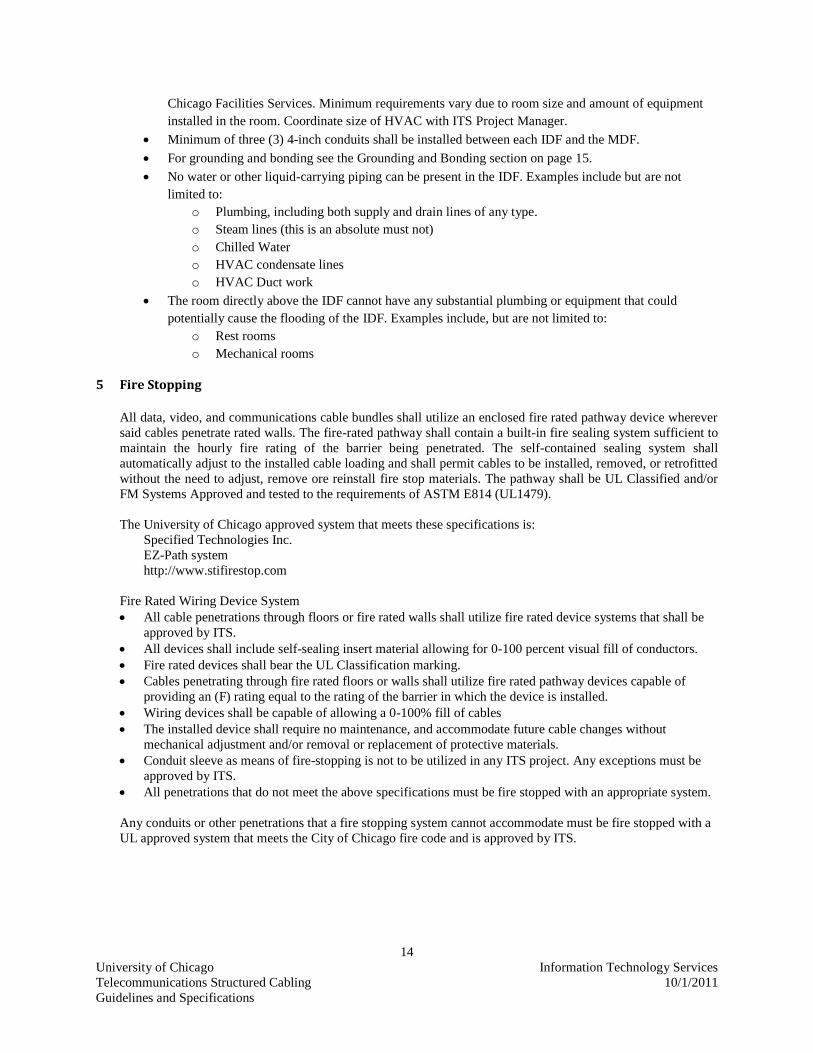
5 Fire Stopping
All data, video, and communications cable bundles shall utilize an enclosed fire rated pathway device wherever
said cables penetrate rated walls. The fire-rated pathway shall contain a built-in fire sealing system sufficient to
maintain the hourly fire rating of the barrier being penetrated. The self-contained sealing system shall
automatically adjust to the installed cable loading and shall permit cables to be installed, removed, or retrofitted
without the need to adjust, remove ore reinstall fire stop materials. The pathway shall be UL Classified and/or
FM Systems Approved and tested to the requirements of ASTM E814 (UL1479).
The University of Chicago approved system that meets these specifications is:
Specified Technologies Inc.
EZ-Path system
http://www.stifirestop.com
Fire Rated Wiring Device System
All cable penetrations through floors or fire rated walls shall utilize fire rated device systems that shall be
approved by ITS.
All devices shall include self-sealing insert material allowing for 0-100 percent visual fill of conductors.
Fire rated devices shall bear the UL Classification marking.
Cables penetrating through fire rated floors or walls shall utilize fire rated pathway devices capable of
providing an (F) rating equal to the rating of the barrier in which the device is installed.
Wiring devices shall be capable of allowing a 0-100% fill of cables
The installed device shall require no maintenance, and accommodate future cable changes without
mechanical adjustment and/or removal or replacement of protective materials.
Conduit sleeve as means of fire-stopping is not to be utilized in any ITS project. Any exceptions must be
approved by ITS.
All penetrations that do not meet the above specifications must be fire stopped with an appropriate system.
Any conduits or other penetrations that a fire stopping system cannot accommodate must be fire stopped with a
UL approved system that meets the City of Chicago fire code and is approved by ITS.

15
University of Chicago Information Technology Services
Telecommunications Structured Cabling 10/1/2011
Guidelines and Specifications
6 Grounding and Bonding
The grounding and bonding infrastructure of a telecommunications installation is an essential part of
telecommunications distribution system. The information in this section does not replace federal, state,
local, or other codes, laws, and regulations.
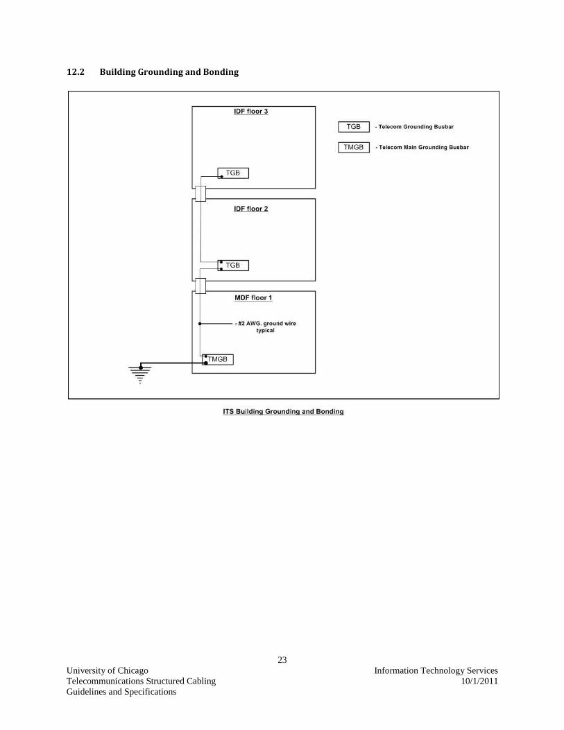
TMGB (Telecommunication Main Grounding Bus Bar) shall be located in the MDF (Main Distribution
Frame). The TMGB shall be a minimum of ¼-inch thick, 4 inches wide, and 12 inches in length.
TGB (Telecommunication Grounding Bus Bar) shall be located in IDFs. The TGB shall be a minimum of
10 inches long and 2 inches wide by ¼-inch thick.
A TBB (Telecommunication Bonding Backbone) shall connect the TMGB (Telecommunication Main
Grounding Bus Bar) and TGB (Telecommunication Grounding Bus Bar).
All basket tray, ladder rack, equipment racks and or cabinets within the MDF and IDF shall be grounded/
bonded to the TMGB or TGB. A minimum size BC (bonding conductor) of 6 AWG shall be used.
16
University of Chicago Information Technology Services
Telecommunications Structured Cabling 10/1/2011
Guidelines and Specifications
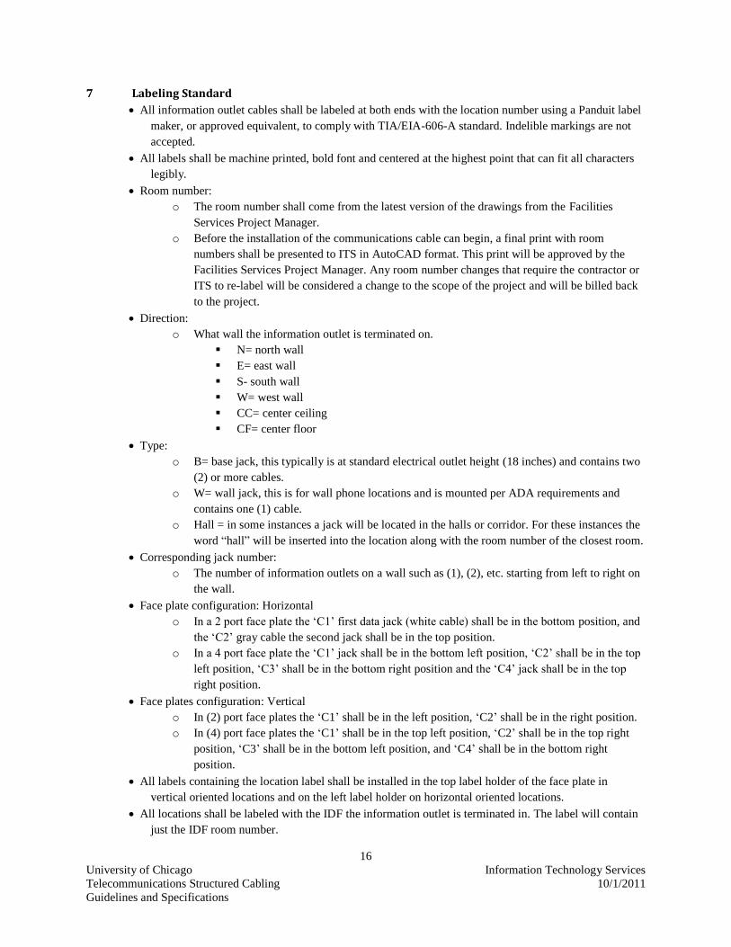
7 Labeling Standard
All information outlet cables shall be labeled at both ends with the location number using a Panduit label
maker, or approved equivalent, to comply with TIA/EIA-606-A standard. Indelible markings are not
accepted.
All labels shall be machine printed, bold font and centered at the highest point that can fit all characters
legibly.
Room number:
o The room number shall come from the latest version of the drawings from the Facilities
Services Project Manager.
o Before the installation of the communications cable can begin, a final print with room
numbers shall be presented to ITS in AutoCAD format. This print will be approved by the
Facilities Services Project Manager. Any room number changes that require the contractor or
ITS to re-label will be considered a change to the scope of the project and will be billed back
to the project.
Direction:
o What wall the information outlet is terminated on.
N= north wall
E= east wall
S- south wall
W= west wall
CC= center ceiling
CF= center floor
Type:
o B= base jack, this typically is at standard electrical outlet height (18 inches) and contains two
(2) or more cables.
o W= wall jack, this is for wall phone locations and is mounted per ADA requirements and
contains one (1) cable.
o Hall = in some instances a jack will be located in the halls or corridor. For these instances the
word “hall” will be inserted into the location along with the room number of the closest room.
Corresponding jack number:
o The number of information outlets on a wall such as (1), (2), etc. starting from left to right on
the wall.
Face plate configuration: Horizontal
o In a 2 port face plate the „C1‟ first data jack (white cable) shall be in the bottom position, and
the „C2‟ gray cable the second jack shall be in the top position.
o In a 4 port face plate the „C1‟ jack shall be in the bottom left position, „C2‟ shall be in the top
left position, „C3‟ shall be in the bottom right position and the „C4‟ jack shall be in the top
right position.
Face plates configuration: Vertical
o In (2) port face plates the „C1‟ shall be in the left position, „C2‟ shall be in the right position.
o In (4) port face plates the „C1‟ shall be in the top left position, „C2‟ shall be in the top right
position, „C3‟ shall be in the bottom left position, and „C4‟ shall be in the bottom right
position.
All labels containing the location label shall be installed in the top label holder of the face plate in
vertical oriented locations and on the left label holder on horizontal oriented locations.
All locations shall be labeled with the IDF the information outlet is terminated in. The label will contain
just the IDF room number.
17
University of Chicago Information Technology Services
Telecommunications Structured Cabling 10/1/2011
Guidelines and Specifications
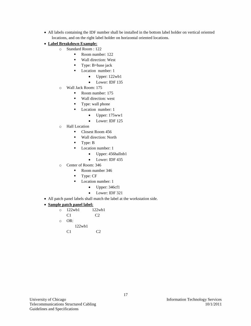
All labels containing the IDF number shall be installed in the bottom label holder on vertical oriented
locations, and on the right label holder on horizontal oriented locations.
Label Breakdown Example:
o Standard Room : 122
Room number: 122
Wall direction: West
Type: B=base jack
Location number: 1
Upper: 122wb1
Lower: IDF 135
o Wall Jack Room: 175
Room number: 175
Wall direction: west
Type: wall phone
Location number: 1
Upper: 175ww1
Lower: IDF 125
o Hall Location
Closest Room 456
Wall direction: North
Type: B
Location number: 1
Upper: 456hallnb1
Lower: IDF 435
o Center of Room: 346
Room number 346
Type: CF
Location number: 1
Upper: 346cf1
Lower: IDF 321
All patch panel labels shall match the label at the workstation side.
Sample patch panel label:
o 122wb1 122wb1
C1 C2
o OR:
122wb1
C1 C2

18
University of Chicago Information Technology Services
Telecommunications Structured Cabling 10/1/2011
Guidelines and Specifications
8 Testing and Documentation
8.1 General
Acceptance testing shall be completed and documentation provided to the University as soon as
possible in order to permit the installation of networking equipment necessary to bring the building online
for security and equipment monitoring systems.
The University shall have the right to schedule acceptance testing at its convenience.
A University representative, at the option of the University, shall be present during testing.
Such acceptance testing shall in no way reduce the Contractors' obligations regarding restoration, clean
up or warranty.
Contractor shall perform tests necessary to ensure that the installed cables will pass acceptance testing
performed in conjunction with University representatives.
Contractor shall be responsible for performing, tracking, and recording the results of tests.
Contractor shall be responsible for providing equipment and materials necessary for as long a period of
time as necessary to complete testing to the satisfaction of the University.
Test record forms shall be agreed to by the University prior to the commencement of acceptance
testing.
8.2 Documentation
At minimum, the data provided must include the following elements:
Provide record plant documentation, including jack type (Information outlet), jack location, circuit
length, fiber riser cable lengths, and copper backbone cable lengths and any other information deemed
to be useful.
The documentation format(s) will be agreed upon between ITS and the contractor.
Provide all documentation in electronic format.
Cable routing.
Riser and OSP cable, pair (count), locations, and final cable lengths.
Supporting structures.
Terminal locations and IDs.
IDF Room and terminal details.
Pull box locations, including elevations and sizes.
Information Outlet locations, label IDs, types, and serving IDF.
For each change reflected on the Record Drawings, the Change Order Request number shall be shown.
19
University of Chicago Information Technology Services
Telecommunications Structured Cabling 10/1/2011
Guidelines and Specifications
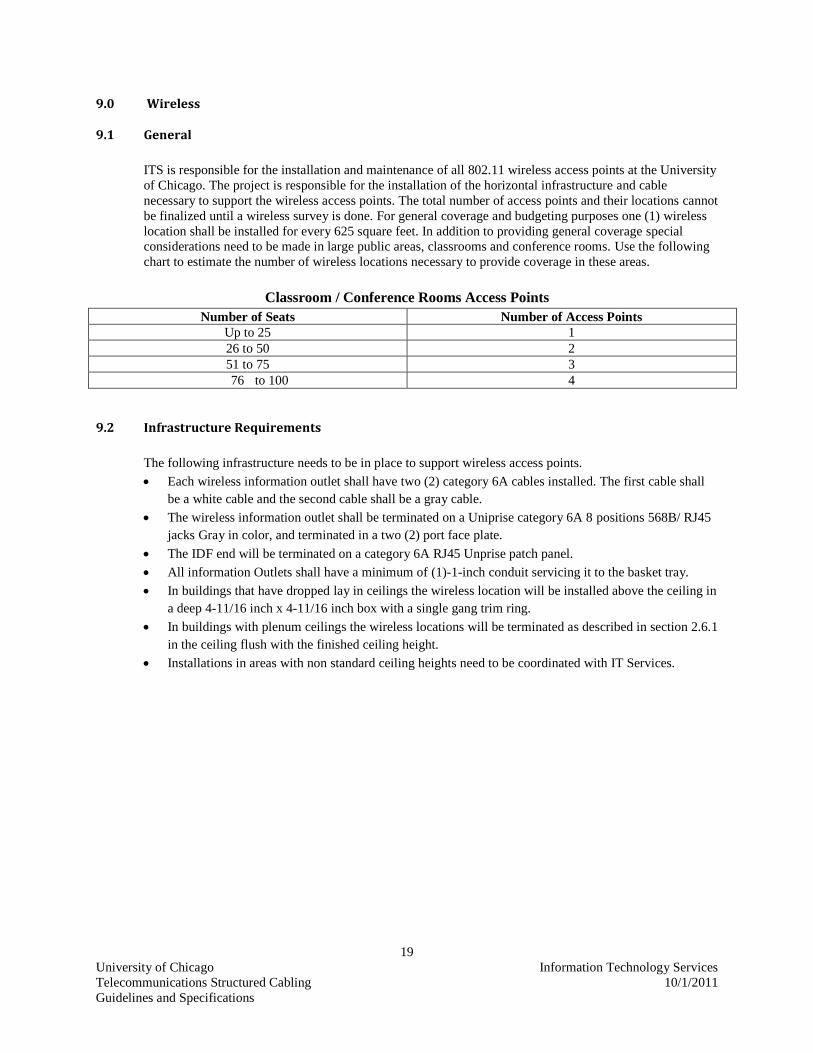
9.0 Wireless
9.1 General
ITS is responsible for the installation and maintenance of all 802.11 wireless access points at the University
of Chicago. The project is responsible for the installation of the horizontal infrastructure and cable
necessary to support the wireless access points. The total number of access points and their locations cannot
be finalized until a wireless survey is done. For general coverage and budgeting purposes one (1) wireless
location shall be installed for every 625 square feet. In addition to providing general coverage special
considerations need to be made in large public areas, classrooms and conference rooms. Use the following
chart to estimate the number of wireless locations necessary to provide coverage in these areas.
Classroom / Conference Rooms Access Points
Number of Seats Number of Access Points
Up to 25 1
26 to 50 2
51 to 75 3
76 to 100 4
9.2 Infrastructure Requirements
The following infrastructure needs to be in place to support wireless access points.
Each wireless information outlet shall have two (2) category 6A cables installed. The first cable shall
be a white cable and the second cable shall be a gray cable.
The wireless information outlet shall be terminated on a Uniprise category 6A 8 positions 568B/ RJ45
jacks Gray in color, and terminated in a two (2) port face plate.
The IDF end will be terminated on a category 6A RJ45 Unprise patch panel.
All information Outlets shall have a minimum of (1)-1-inch conduit servicing it to the basket tray.
In buildings that have dropped lay in ceilings the wireless location will be installed above the ceiling in
a deep 4-11/16 inch x 4-11/16 inch box with a single gang trim ring.
In buildings with plenum ceilings the wireless locations will be terminated as described in section 2.6.1
in the ceiling flush with the finished ceiling height.
Installations in areas with non standard ceiling heights need to be coordinated with IT Services.

20
University of Chicago Information Technology Services
Telecommunications Structured Cabling 10/1/2011
Guidelines and Specifications
10.0 Security Systems
It is the responsibility of the Department of Safety and Security (DSS) for the procurement and placement,
of all Emergency Phones, Building Access Systems, and Security Cameras.
10.1 Emergency Phones
The installation of an emergency phone will require the following
Two (2) 1-inch conduits installed back into the specified building for each emergency phone. Looping
of conduit between emergency phones is not acceptable.
o One conduit is to be run back to the nearest electrical circuit panel and will require a 120v
20amp circuit.
o The other conduit must have a path way to terminate directly into a network room (IDF or
MDF).
Four (4) category 6A communications cables installed. In order to reach the camera mounted at the top
of the e-phone it is necessary to leave 15 feet of cable coiled within the e-phone.
ITS will work with the Department of Safety and Security to have a carrier provide voice circuit. DSS
will be responsible for the circuit‟s monthly charges.
ITS will provide the concrete contractor with a J-Bolt pattern template along with the J-Bolts. NO
SUBSTITUTIONS can be made.

21
University of Chicago Information Technology Services
Telecommunications Structured Cabling 10/1/2011
Guidelines and Specifications
11.0 Classrooms / Conference Rooms
11.1 General
Need information from other group for specifications
11.2 Audio Visual Need information from other group for specifications
11.3 Wireless
Each classroom or conference room will have at least one (1) 802.11 wireless access point. The
access points will be installed as outlined in section 9.0. For the number of access point to be
installed in each classroom please refer to the following table.
Classroom / Conference Rooms Access Points
Number of Seats Number of Access Points
Up to 25 1
26 to 50 2
51 to 75 3
76 to 100 4

22
University of Chicago Information Technology Services
Telecommunications Structured Cabling 10/1/2011
Guidelines and Specifications
12.0 Diagrams
12.1 Conduit Fill Capacity
Conduit Fill Capacity
40%
Conduit Size Category 6 Category 6A
1-inch 6 4
2-inch 22 17
3-inch 49 37
4-inch 83 64
23
University of Chicago Information Technology Services
Telecommunications Structured Cabling 10/1/2011
Guidelines and Specifications
12.2 Building Grounding and Bonding

24
University of Chicago Information Technology Services
Telecommunications Structured Cabling 10/1/2011
Guidelines and Specifications
12.3 Equipment Rack Grounding and Bonding

25
University of Chicago Information Technology Services
Telecommunications Structured Cabling 10/1/2011
Guidelines and Specifications
12.4 Sample ITS Main Distribution Frame (MDF)
26
University of Chicago Information Technology Services
Telecommunications Structured Cabling 10/1/2011
Guidelines and Specifications
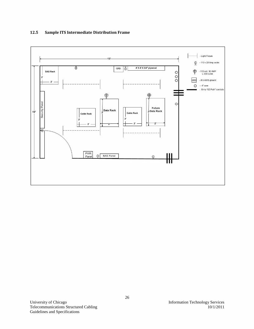
12.5 Sample ITS Intermediate Distribution Frame


