27
| Date post: | 13-Apr-2015 |
| Category: |
Documents |
| Upload: | vincent-teng |
| View: | 197 times |
| Download: | 18 times |


STRUT AND TIE MODELLINGBackground and New AS 3600 Provisions
Peter DuxThe University of Queensland
Background 1:B and D regions
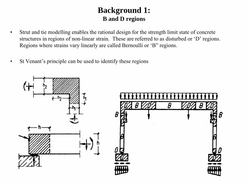
• Strut and tie modelling enables the rational design for the strength limit state of concrete structures in regions of non-linear strain. These are referred to as disturbed or ‘D’ regions. Regions where strains vary linearly are called Bernoulli or ‘B” regions.
• St Venant’s principle can be used to identify these regions

• The model has struts, a tie and nodes. • Struts and nodes have volume. Centrelines of struts and ties bisect the near face of the nodal
zone and intersect at a common point or node.• Shear is transferred to supports via concrete struts. The orientation of struts is dictated by the
shear diagram.• The distribution of internal forces and the reactions must satisfy equilibrium. Material
capacity must not be exceeded.• Internal forces are stress resultants i.e. design is based on stresses in concrete and steel.
Sketch of possible strut and tie model of a deep beam - the whole beam is a D region.
Background 2:Plasticity and the Lower-bound Theorem – the Basis of Strut and Tie Design
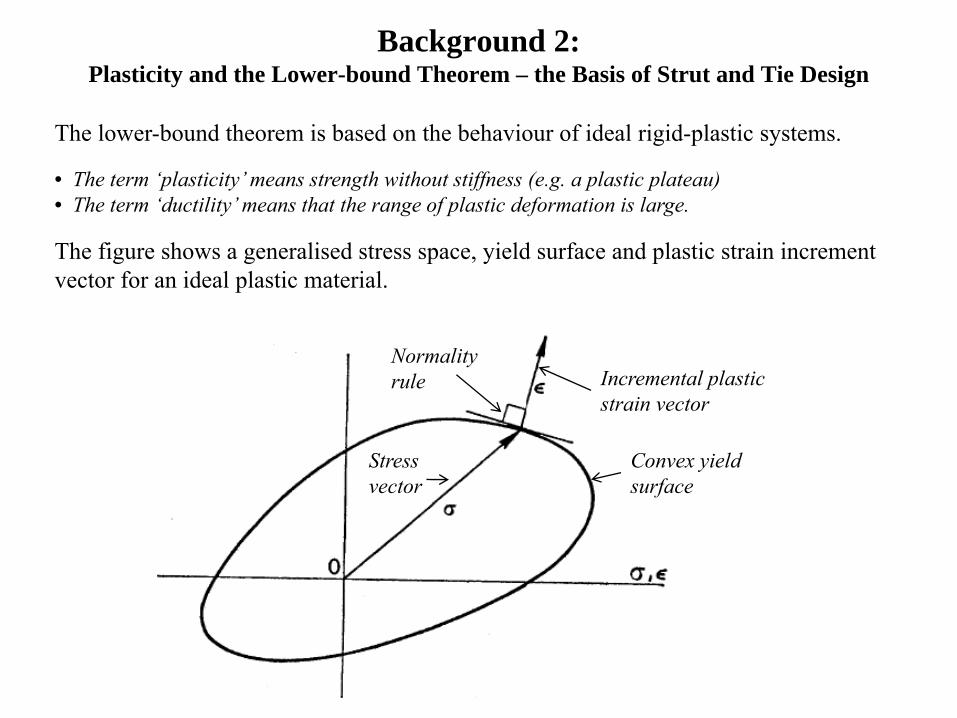
The lower-bound theorem is based on the behaviour of ideal rigid-plastic systems.
• The term ‘plasticity’ means strength without stiffness (e.g. a plastic plateau)• The term ‘ductility’ means that the range of plastic deformation is large.
The figure shows a generalised stress space, yield surface and plastic strain increment vector for an ideal plastic material.
Convex yield surface
Incremental plastic strain vector
Normality rule
Stress vector

This figure shows a generalised rigid-plastic structure with generalised loading, Wi , at the point of collapse.
Consider now a design situation:
Suppose a designer has determined some internal stress distribution , σ* , which does not violate the yield surface and which equilibrates a design loading, λWi . The designer has not considered compatibility.
This is typical of design for strength.Internal stresses, σ, are on or within the material yield surface
Incremental displacement component in the load direction at a load point during collapse

At collapse:External work = Internal work
Σ Wi ui = ∫σ. ε dV
where the dot denotes a scalar product. The integral relates only to stresses on the yield surface and the local plastic strain increments as the material is rigid-plastic. However, for small collapse deformations, elastic regions in elastic-plastic materials do not deform (i.e. they are essentially rigid) and only stresses on the yield surface do work.
Impose the collapse deformations as a set of virtual deformations on the structure with loads λWi .
The work equation becomesΣ λWi ui = ∫σ*. ε dV
But, everywhere in the structure, the stress state, σ*, lies on or within the yield surface. Therefore,
σ. ε ≥ σ*. ε at all points in the structure.
Hence λ ≤ 1.0
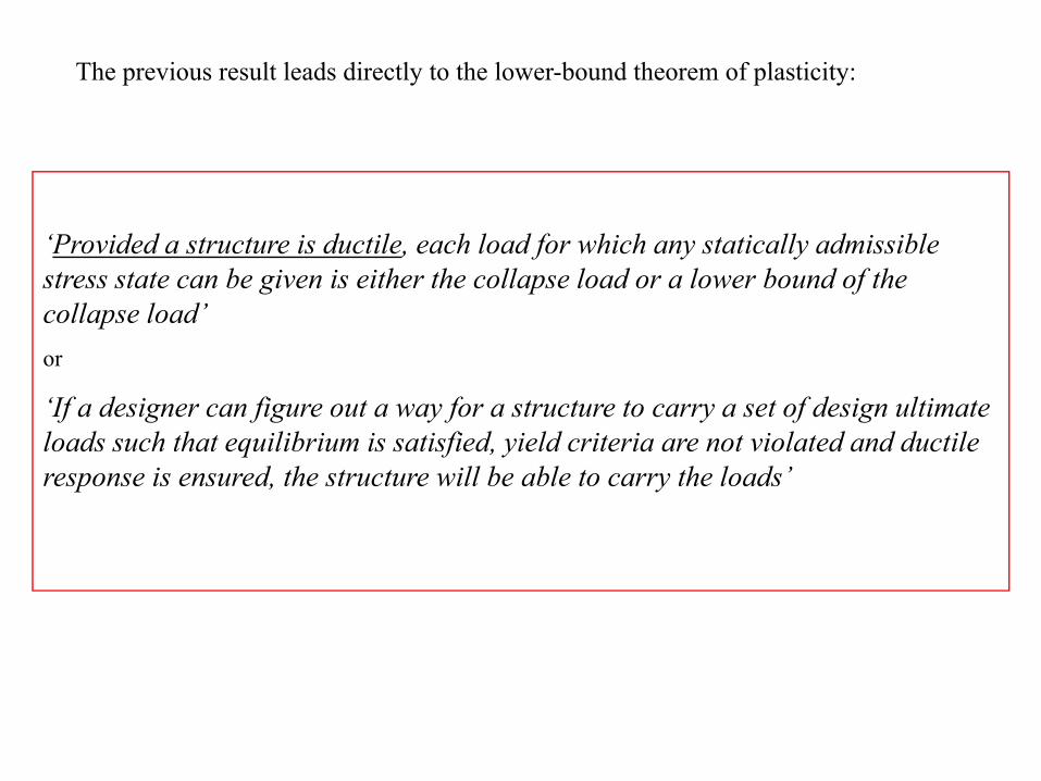
‘Provided a structure is ductile, each load for which any statically admissible stress state can be given is either the collapse load or a lower bound of the collapse load’or
‘If a designer can figure out a way for a structure to carry a set of design ultimate loads such that equilibrium is satisfied, yield criteria are not violated and ductile response is ensured, the structure will be able to carry the loads’
The previous result leads directly to the lower-bound theorem of plasticity:

• Ignoring strain-hardening, steel exhibits plasticity and is ductile .
• Plain concrete exhibits neither plasticity nor ductility.
• Properly designed concrete structures do not have unlimited ductility. Therefore the choice of a ‘statically admissible stress state’ must be done with good judgement.
• The challenge in design of concrete structures for strength is to have yield of steel dominate the failure mode.
• Concrete stresses must be closely controlled to prevent brittle failure. Otherwise, adoption of the lower-bound theorem ,which assumes a good range of plastic response , is invalidated.
• The chosen stress state should reflect the way the structure naturally carries loads, for example, as indicated by elastic analysis. The strut and tie approach is a design methodology, not an analysis methodology.
Background 3:Concrete structures do not have unlimited ductility

Longitudinal stresses
Transverse stresses
Longitudinal stresses
Transverse stresses
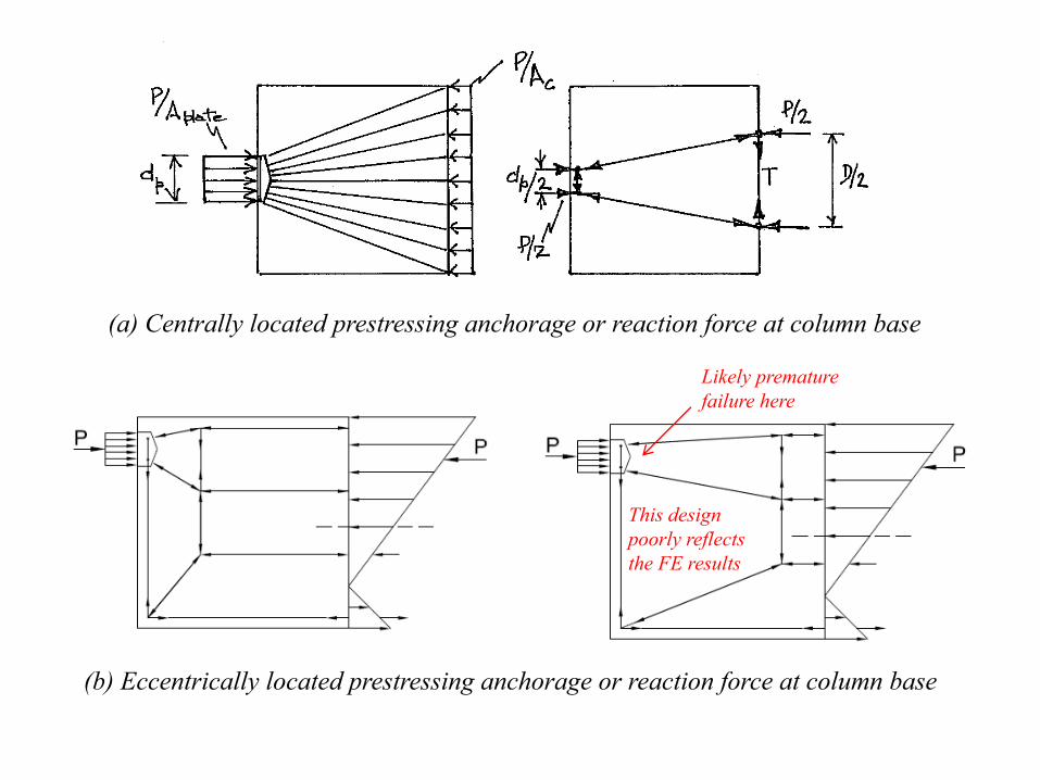
(a) Centrally located prestressing anchorage or reaction force at column base
(b) Eccentrically located prestressing anchorage or reaction force at column base
These stress distributions are reasonably consistent with prediction based on application of St Venant’s principle
Here, the stress distributions are not so intuitively obvious, even though stresses have settled down at the right-hand boundary of the D region.
zone of tension
zone of compression
(a) Centrally located prestressing anchorage or reaction force at column base
(b) Eccentrically located prestressing anchorage or reaction force at column base
This design poorly reflects the FE results
Likely premature failure here
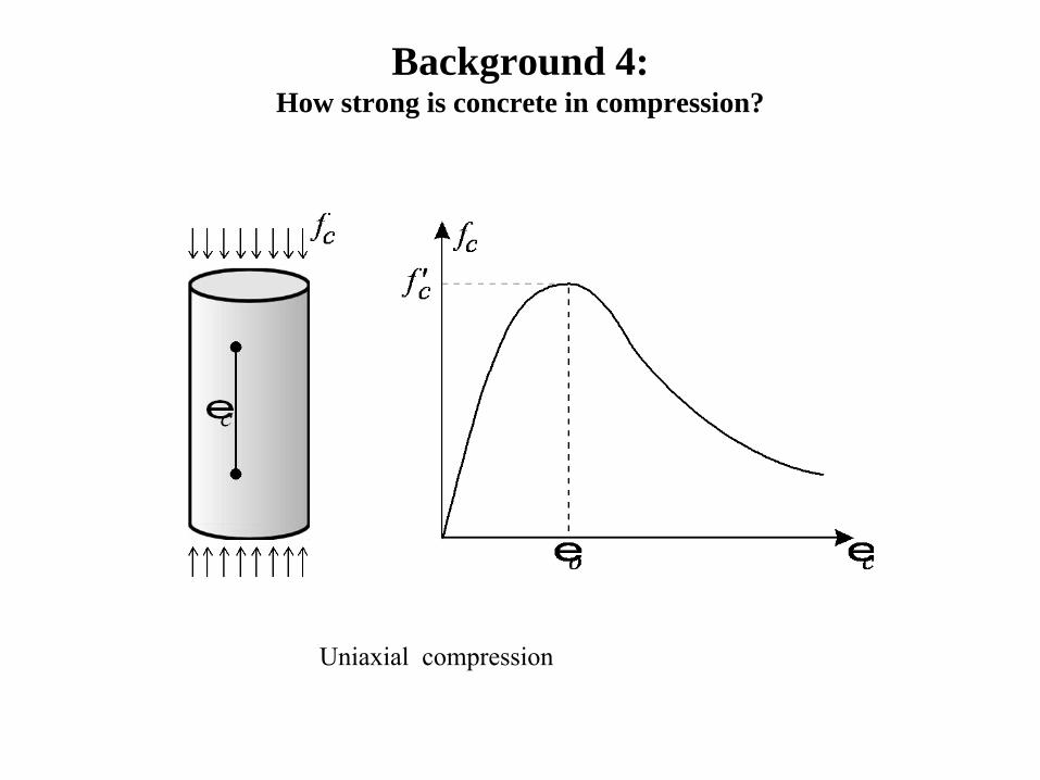
Background 4:How strong is concrete in compression?
Uniaxial compression

Transverse tensile strain reduces compressive strength due to enhanced cracking. Transverse compression increases the compressive strength.
cc
cmax ff
f '1708.0'
1
≤+
=ε

e2e1
es
Strain conditions at a node
s
( ) sss θεεεε 221 cot−+=
From Mohr’s circle of strain:
45° 0.004 0.68
30° 0.010 0.40
25° 0.015 0.30 cf '
cf '
cf 'sθ 1ε
cc
cmax ff
f '1708.0'
1
≤+
=ε
With ε2 = -0.002 and εs estimated as 0.001 (around half the yield strain of steel) the compressive strength of the strut becomes
fcmax
This effect has been confirmed in tests of strut and tie structures.
sθAs reduces, the principal tensile strainincreases and cracks in the transition zone become wider and more skew to the strut.
2ε

AS 3600 provisions 1:Material capacity reduction factors
• The new code uses material capacity reduction factors for strut and tie design.
• The concrete factor is lower - concrete has less quality control than steel.
6.0=concreteφ8.0=steelφ
Both are referred to as in AS 3600stφ
Code ( reinforcement) (prestressing)
AS 3600 0.6 0.8 0.8
Eurocode 0.67 0.87 0.87Canadian 0.6 0.85 0.9
cφ sφ sφ

AS 3600 provisions 2:Minimum angle between any strut and any tie at a node
For reinforced concrete, θmin = 30o
For prestressed concrete, θmin = 20o
• Cracks in the vicinity of nodes with prestressed ties develop later in loading and are less severe than cracks in the vicinity of nodes with non-prestressed ties.
• The Eurocode specifies a minimum of around 22o for either type of reinforcement.But• For small θ, concrete capacity is severely limited (as has been seen) .
• Forces in flat struts are typically high because the vertical component has to equal the shear being carried i.e. the law of diminishing returns quickly comes into play as θ reduces.
C

AS 3600 provisions 3:Design strength of struts
Design strength = c βs 0.9f’c Acφi.e. Design stress = 0.54 βs f ’c
where βs ,the ‘strut efficiency factor’ = 0.3≤ βs ≤ 1.0 θ2cot66.00.1
0.1+
and Ac is the minimum cross-sectional area of the strut
General:
Additional requirements where a strut enters a node:Incoming axial stress in the strut (code refers to ‘principal compressive stress on nodal face’, which is the same thing) ≤ 0.54 βn f’c
At nodes with no ties (CCC) βn = 1.0At nodes with 1 tie (CCT) βn = 0.8At nodes with more than 1 tie (CTT) βn = 0.6
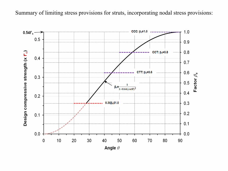
Summary of limiting stress provisions for struts, incorporating nodal stress provisions:

0
0.1
0.2
0.3
0.4
0.5
20 30 40 50 60 70
Des
ign
stre
ss (x
f'c)
Strut angle θs (i.e.θ)
AS 3600
.001
.0015
.002
.0025
εs
Comparison of AS 3600 design stresses for struts with design stresses based on Canadian code formula, for various values of average strain in reinforcement, εs , in nodal zone.
( ) sss θεεεε 221 cot−+=
cc
cmax ff
f '1708.0'
1
≤+
=ε
, and design stress = 0.6 fcmaxe2e1
es
Strain conditions at a node
s
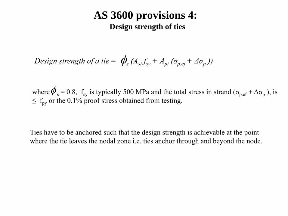
AS 3600 provisions 4:Design strength of ties
Design strength of a tie = s (Ast fsy + Apt (σp.ef + Δσp )) φ
where s = 0.8, fsy is typically 500 MPa and the total stress in strand (σp.ef + Δσp ), is ≤ fpy or the 0.1% proof stress obtained from testing.
φ
Ties have to be anchored such that the design strength is achievable at the point where the tie leaves the nodal zone i.e. ties anchor through and beyond the node.

Δσp Ap = 0.5W
Effective prestressing force PE = Apt σp.ef (here, = 1.5 Pw ) applied as a nodal force
SupposePE = 1.5 W
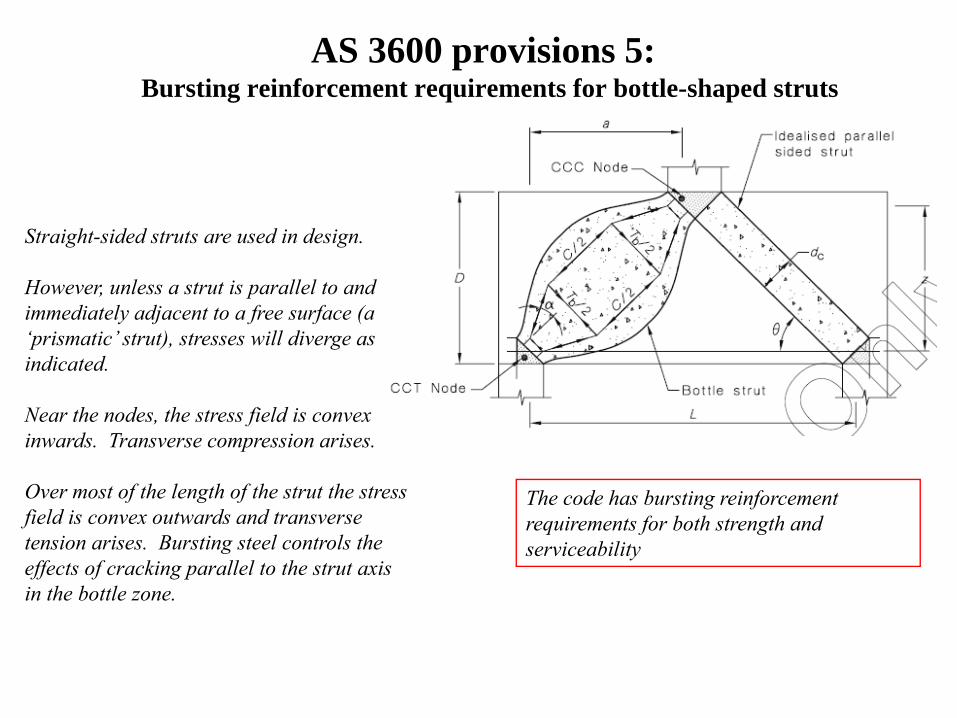
AS 3600 provisions 5:Bursting reinforcement requirements for bottle-shaped struts
Straight-sided struts are used in design.
However, unless a strut is parallel to and immediately adjacent to a free surface (a ‘prismatic’ strut), stresses will diverge as indicated.
Near the nodes, the stress field is convex inwards. Transverse compression arises.
Over most of the length of the strut the stress field is convex outwards and transverse tension arises. Bursting steel controls the effects of cracking parallel to the strut axis in the bottle zone.
The code has bursting reinforcement requirements for both strength and serviceability
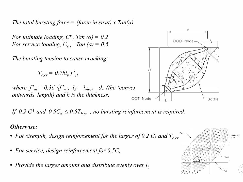
The total bursting force = (force in strut) x Tan(α)
For ultimate loading, C*, Tan (α) = 0.2For service loading, Cs , Tan (α) = 0.5
The bursting tension to cause cracking:
Tb.cr = 0.7blb f’ct
where f’ct = 0.36 √f ’c , lb = lstrut – dc (the ‘convex outwards’ length) and b is the thickness.
• For strength, design reinforcement for the larger of 0.2 C* and Tb.cr
• For service, design reinforcement for 0.5Cs
• Provide the larger amount and distribute evenly over lb
If 0.2 C* and 0.5Cs ≤ 0.5Tb.cr , no bursting reinforcement is required.
Otherwise:
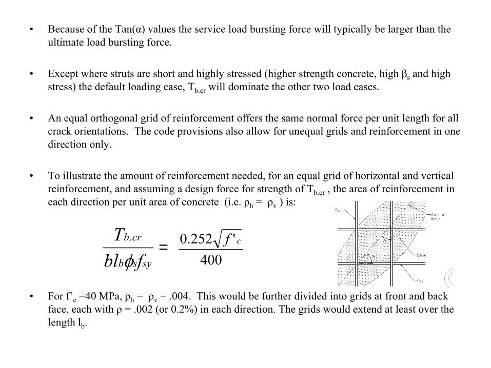
• Because of the Tan(α) values the service load bursting force will typically be larger than the ultimate load bursting force.
• Except where struts are short and highly stressed (higher strength concrete, high βs and high stress) the default loading case, Tb.cr will dominate the other two load cases.
• An equal orthogonal grid of reinforcement offers the same normal force per unit length for all crack orientations. The code provisions also allow for unequal grids and reinforcement in one direction only.
• To illustrate the amount of reinforcement needed, for an equal grid of horizontal and vertical reinforcement, and assuming a design force for strength of Tb.cr , the area of reinforcement in each direction per unit area of concrete (i.e. ρh = ρv ) is:
• For f’c =40 MPa, ρh = ρv = .004. This would be further divided into grids at front and back face, each with ρ = .002 (or 0.2%) in each direction. The grids would extend at least over the length lb.
sysb
crb
fblTφ
.
400'252.0 cf=

For a minor degree of crack control 250 MPaFor a moderate degree of crack control 200 MPaFor a strong degree of crack control 150 MPa
Design for serviceability:
The design force = 0.5Cs
The design stress in reinforcement:
Sufficient reinforcement at the chosen stress is required to provide the design force normal to the crack.
An equal orthogonal grid provides this force in both directions (e.g. horizontally and vertically). The requirement is then halved for grids at front and back face.
The strut length does not feature; hence, the longer the strut the lower the percentage of reinforcement required.
Even if the design forces for both ultimate and service load cases are less than 0.5Tb.cr , grids of reinforcement should be provided at front and back faces.

Summary of bursting reinforcement requirements:
The bursting force, Tb is defined as follows:
For strength, T*b = 0.2C*
For serviceability Tbs = 0.5Cs
Bursting reinforcement is required if T*b or Tbs > 0.5Tb.cr
where Tb.cr = 0.7blb f’ct
For orthogonal reinforcement, the provided horizontal and vertical reinforcement must satisfy
bs
b
h
sh
v
sv
lfT
sA
sA
≥+ θθ 22 sincos
where θ is the inclination of the strut from the horizontal.
For strength, Tb is the larger of T*b and Tb.cr ; fs = fsy
For service, Tb = Tbs ; fs = 150, 200 or 250 MPa
sφ
Conclusions
• The new AS 3600 provisions for strut and ties design are a major change for the better.
• AS 3600 now uses material capacity reduction factors rather than a single capacity reduction factor (0.7). Arguably, the factor for steel (0.8) is still low. The limiting stresses for struts are conservative rather than liberal.
• For code-surfers, the Eurocode provisions are typically less stringent for about the same ultimate loading (1.25G + 1.5Q for most situations).
Sources:1. Standards Australia, Draft standard DR 05252, 20072. Chris Calladine, “Engineering Plasticity”, Pergamon,19693. Scott Rathie, HonoursThesis, UQ, 20074. Nick Stevens, various.5. Schlaich , J et al, “Towards a consistent design of structural concrete”, PCI ,32,3,1987


