NAT L INST. OF STAND & TECH R IX r AlllOS flb512D MIST PUBLICATIONS 10.960-1 flOO Installing Maintaining, Verifying Your Charpy Impact Machine STTR D.P. Vigliotti T.A. Siewert C.N. McCowan Nisr National Institute of Standards and Technology Technology Administration U.S. Department of Commerce Special Publication 960-4
U.S. Department of CommerceNorman Y. Mineta, Secretary
Technology Administration
Dr. Cheryl L. Shavers, Under Secretary of
Commerce for Technology
National Institute of Standards and Technology
Raymond G. Kammer, Director
Certain commercial entities, equipment, or materials may be identified in this
document in order to describe an experimental procedure or concept adequately.
Such identification is not intended to imply recommendation or endorsement
by the National Institute of Standards and Technology, nor is it intended to
imply that the entities, materials, or equipment are necessarily the best avail-
able for the purpose.
National Institute of Standards and Technology
Special Publication 960-4
Natl. Inst. Stand. Technol.
Spec. Publ. 960-4
22 pages (October 2000)
CODEN: NSPUE2
U.S. GOVERNMENT PRINTING OFFICEWASHINGTON: 2000
For sale by the Superintendent of Documents
U.S. Government Printing Office
Washington, DC 20402-9325
Foreword
This Special Publication is a reprint of NIST Technical Note 1500-8, a TNseries started by the Materials Reliability Division. This TN series describes
their division's significant research accomplishments in measurement technol-
ogy, reported so that producers and users of materials can improve the quality
and reliability of their products.
This particular Practice Guide provides practical advice on how to correct
problems discovered during the testing of Standard Reference Materials 2092,
2096, and 2098 on Charpy impact machines. Although only a small percent-
age of machines fail to meet the requirements during their annual performance
tests, the failure of a machine can have large economic implications to the
machine's owners, and we try to assist in correcting the problems. From the
study of the fractured specimens and test data that are returned to NIST for
evaluation, we have learned how to identify many of the common problems.
Also, over the years, we have had discussions with thousands of engineers and
technicians at these companies, and have learned the most efficient sequences
for identifying the sources of the problem and for correcting them. Now, we
have collected and organized the various problems and solutions in this
Special Publication. We hope that you will find it useful for installing a new
machine correctly, and then for preparing for the annual verification tests.
More information on the SP 960 series can be found on the Internet at
http://www.nist.gov/practiceguides. This web site includes a complete
list of NIST Practice Guides and ordering information.
Abstract:
The quality of the data developed by pendulum impact machines depends on
how well the machines are installed, maintained, and verified. This is the rea-
son that ASTM Standard E 23 Standard Test Methods for Notched Bar Impact
Testing of Metallic Materials specifies annual direct and indirect verification
tests. Each year, NIST provides reference specimens for indirect verification of
over 1000 machines around the world. From evaluation of the absorbed ener-
gies and the fractured specimens, we attempt to deduce the origin of energies
that are outside the ranges permitted by Standard E 23, and report these obser-
vations back to the machine owners. This recommended practice summarizes
the bases for these observations, and hopefully will allow machines to be
maintained at higher levels of accuracy. In addition, we provide details of the
NIST verification program procedures and the production of the specimens.
This section of the practice explains the direct verification requirements of
Standard E 23. confirmation that the machine is in good operating condition,
without the use of verification specimens. The direct verification tests are
physics-based tests, which assure that the machine is functioning as closely as
possible to a simple pendulum, with only small losses, due to friction and
windage. Direct verification is most important when the machine is first
installed or when major parts are replaced, but is also important during the
periodic reinspections. While these tests are required for the periodic reinspec-
tions, we recommend that the free-swing test and windage-and-friction test be
performed each day that the machine is used. The records of these tests then
serve as a convenient measure of bearing performance.
Since the Charpy test is a dynamic test with vibration and impact loads, the
hold-down bolts may loosen over time. In extreme cases, this may introduce
error sufficient to cause a machine to exceed the tolerance limits of the indi-
rect verification test. In marginal cases, the movement may still be sufficient
to add a bias to the results that reduces the likelihood of passing. Check the
tightness of all bolts, especially the anvil bolts, the striker bolts, and the base-
plate bolts. The manufacturer can supply the torque values for the anvil and
striker bolts. The base-plate bolts should be torqued to the recommended
torque values for the grade and size of the nuts and bolts. We recommend the
use of "J" or "T" bolts only. We do not recommend lag-type bolts. These are
made to withstand only static loads. We believe that over time, the insert por-
tion of lag bolts can loosen in the concrete. When lag bolts are retightened.
they can pull out of the concrete and be pulled against the base of the machine
.
giving the impression of a properly mounted machine. This condition is very
difficult to detect. A machine with this problem will exhibit erroneously high
energy values at the low-energy level. The mounting procedure used to elimi-
nate this problem for our Master Reference Machines was described in the
previous section.
Standard E 23 describes a routine check procedure that should be performed
weekly. It consists of a free-swing check and a friction-and-windage check.
The free swing is a quick and simple test to determine whether the dial or
readout is performing accurately. A proper zero reading after one swing from
the latched position is required on a machine that is equipped with a compen-
sated dial. Some machines are equipped with a non-compensated dial. Such
a dial is one on which the indicator cannot be adjusted to read zero after one
free swing. The user should understand the procedure for dealing with a
non-compensated dial. This information should be available from the
manufacturer.
7
W Direct Verification
The friction-and-windage test assesses the condition of the bearings. The pen-
dulum should be released and allowed to swing 10 half cycles (5 full swings).
(We recommend holding the release mechanism down this whole time to avoid
additional friction when the pendulum swings back up to where it may push
on the latch.) As the pendulum starts its 11th half swing, the pointer should be
reset to about 5 % of the scale capacity. Record this value and divide by the 1
1
half swings. Divide this number by the machine range capacity, then multiply
by 100. Any loss of more than 0.4 % of the machine capacity is excessive, and
the bearings should be inspected.
We suggest that the user develop a daily log or shift log to be kept with the
machine. The log can be used to track the zero and friction values. The log can
also include information such as number of tests, materials tested, mainte-
nance, and any other useful comments.
The anvil and striker radii should be carefully inspected for damage and for
proper dimensions. Damage (chips or burrs) can be detected easily by visual
inspection and by running a finger over the radii to check for smoothness.
Measurement of the dimensions requires more sophisticated equipment. Wefind that radius gages are usually inadequate to measure the critical radii. Werecommend making molds of the radii (such as with silicone rubber) or mak-
ing an indentation in a soft, ductile material (such as annealed aluminum), then
measuring the impressions on an optical comparator. Occasionally, even a new
set of anvils and striker may have incorrect radii. We recommend that new
anvils and strikers always be inspected before being installed in the machine.
Since the radii will not have local wear before use (the radii are consistent
along their length), they can be measured directly on an optical comparator or
other optical measurement system.
8
Indirect Verification
5. Indirect Verification
Indirect verification uses carefully characterized test specimens to stress the
test machine components to levels similar to those experienced during routine
usage. Since many machine problems, such as loose anvils or striker, cannot
be detected during direct verification, indirect verification serves as an impor-
tant supplemental test of the machine performance.
We recommend using centering tongs, such as those described in ASTMStandard E 23. to insert the specimens at the center of the anvils. The tongs
should be inspected for wear or damage. A proper set of tongs is critical for
the accurate placement of the specimen. Some machines are equipped with a
centering device. The device should be inspected for wear and proper opera-
tion. We do not recommend the use of centering devices for low-temperature
testing because the centering operation can extend the time between a speci-
men's removal from the bath and fracture, and so may exceed the five-second
interval allowed for transferring and fracturing the specimen.
Some of the reference specimens are designed to be tested at -40 °C (-40 °F).
Since the absorbed energy changes with temperature, accurate temperature
control is necessary to obtain valid test data. The temperature indicator should
be calibrated immediately before testing. Ice water and dry ice are quick and
easy calibration media.
5.1 Post-Fracture Examination
Just matching the reference energies is not sufficient to confirm that the
machine is fully satisfactor}'. For example, worn anvils can combine with
high-friction bearings to compensate for each other and produce an artificially
correct value during the verification test. These are called compensating errors.
Unfortunately, these errors compensate only over part of the range, so the
machine produces generally inaccurate values. The post-fracture examination
of the NIST standardized verification specimens is a good way to identify such
effects. Therefore, the NIST specimens come with a questionnaire (with criti-
cal questions about the machine and the test procedure) and a mailing label so
the specimens can be returned to NIST. All specimens are examined and com-
pared to the data on the questionnaire before a formal response is sent to the
customers
.
Following are the most common of these problems. In many cases, sugges-
tions on how to correct or avoid them in the future are included.
9
Indirect Verification
5.1.1 Worn Anvils
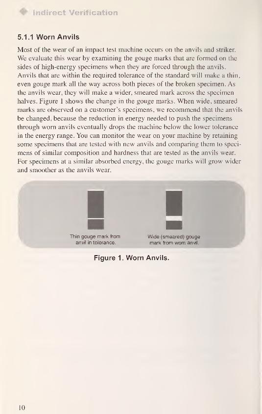
Most of the wear of an impact test machine occurs on the anvils and striker.
We evaluate this wear by examining the gouge marks that are formed on the
sides of high-energy specimens when they are forced through the anvils.
Anvils that are within the required tolerance of the standard will make a thin,
even gouge mark all the way across both pieces of the broken specimen. As
the anvils wear, they will make a wider, smeared mark across the specimen
halves. Figure 1 shows the change in the gouge marks. When wide, smeared
marks are observed on a customer's specimens, we recommend that the anvils
be changed, because the reduction in energy needed to push the specimens
through worn anvils eventually drops the machine below the lower tolerance
in the energy range. You can monitor the wear on your machine by retaining
some specimens that are tested with new anvils and comparing them to speci-
mens of similar composition and hardness that are tested as the anvils wear.
For specimens at a similar absorbed energy, the gouge marks will grow wider
and smoother as the anvils wear.
Figure 1. Worn Anvils.
LO
Post-Fracture Examination
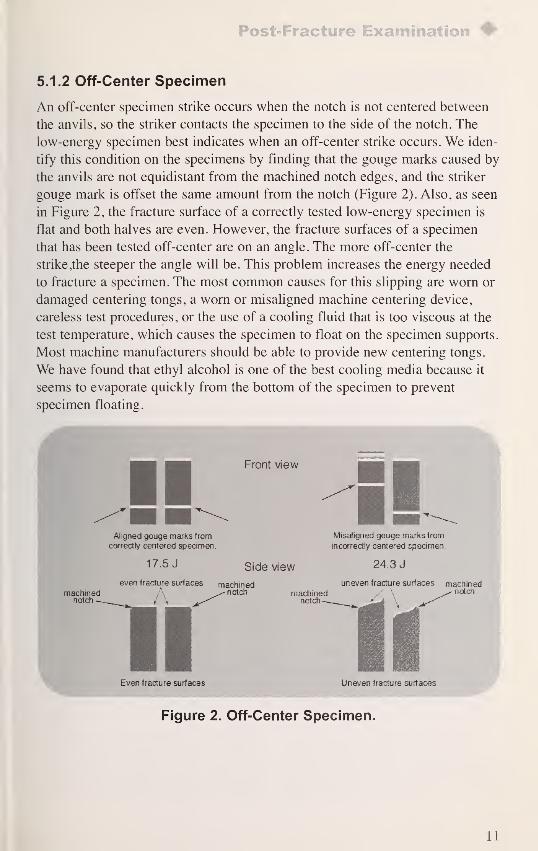
5.1.2 Off-Center Specimen
An off-center specimen strike occurs when the notch is not centered between
the anvils, so the striker contacts the specimen to the side of the notch. The
low-energy specimen best indicates when an off-center strike occurs. We iden-
tify this condition on the specimens by finding that the gouge marks caused by
the anvils are not equidistant from the machined notch edges, and the striker
gouge mark is offset the same amount from the notch (Figure 2). Also, as seen
in Figure 2, the fracture surface of a correctly tested low-energy specimen is
flat and both halves are even. However, the fracture surfaces of a specimen
that has been tested off-center are on an angle. The more off-center the
strike,the steeper the angle will be. This problem increases the energy needed
to fracture a specimen. The most common causes for this slipping are worn or
damaged centering tongs, a worn or misaligned machine centering device,
careless test procedures, or the use of a cooling fluid that is too viscous at the
test temperature, which causes the specimen to float on the specimen supports.
Most machine manufacturers should be able to provide new centering tongs.
We have found that ethyl alcohol is one of the best cooling media because it
seems to evaporate quickly from the bottom of the specimen to prevent
specimen floating.
Even fracture surfaces Uneven fracture surfaces
Figure 2. Off-Center Specimen.
il
Indirect Verification
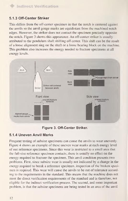
5.1.3 Off-Center Striker
This differs from the off-center specimen in that the notch is centered against
the anvils so the anvil gouge marks are equidistant from the machined notch
edges. However, the striker does not contact the specimen precisely opposite
the notch. Figure 3 shows this appearance. An off-center striker is usually
attributed to the pendulum shaft shifting off center. This shift can be the result
of a loose alignment ring on the shaft or a loose bearing block on the machine.
This problem also increases the energy needed to fracture specimens at all
energy levels.
Figure 3. Off-Center Striker.
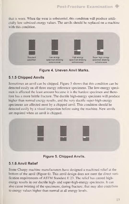
5.1.4 Uneven Anvil Marks
Frequent testing of subsize specimens can cause the anvils to wear unevenly.
Figure 4 shows an example of these uneven wear marks at each energy level
of our reference specimens. Since this wear is restricted to a small area that
the full-size reference specimen contacts, there is usually no effect on the
energy required to fracture the specimen. This anvil condition presents two
problems. First, since subsize wear is usually not indicated by a change in the
energy required to break a reference specimen, inspection of the broken speci-
men is required. This wear will cause the anvils to be out of tolerance accord-
ing to the requirements in the standard. This means that the machine does not
meet the direct verification requirements of the standard and is therefore, not
eligible for the indirect verification process. The second, and more important
problem, is that the subsize specimens are being tested in an area of the anvil
12
Post-Fracture Examination
that is worn. When the wear is substantial, this condition will produce artifi-
cially low subsized energy values. The anvils should be replaced on a machine
with this condition.
IllLow energy
specimen showing
subsize wear
High energy
specimen showing
subsize wear
Super high energy
specimen showing
subsize wear
Figure 4. Uneven Anvil Marks.
5.1.5 Chipped Anvils
Sometimes an anvil can be chipped. Figure 5 shows that this condition can be
detected easily on all three energy reference specimens. The low-energy speci-
men is affected the least amount because it is the hardest specimen and there-
fore has a more brittle fracture. The ductile high-energy specimen will produce
higher than normal energy results, and the very ductile super-high-energy
specimens are affected most by a chipped anvil. This condition should be
detected easily by a visual inspection before using the machine. New anvils
are required when an anvil is chipped.
Figure 5. Chipped Anvils.
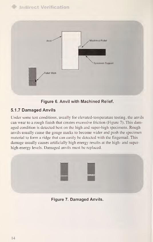
5.1.6 Anvil Relief
Some Charpy machine manufacturers have designed a machined relief at the
bottom of the anvil (Figure 6). This anvil design does not meet the direct veri-
fication requirements ofASTM Standard E 23 . The relief has caused high-
energy results in our ductile high- and super-high-energy specimens. It can
also cause twisting of the specimens, during fracture, that may also contribute
to energy values higher than normal at all energy levels.
13
Indirect Verification
^Relief Mark
Figure 6. Anvil with Machined Relief.
5.1.7 Damaged Anvils
Under some test conditions, usually for elevated-temperature testing, the anvils
can wear to a rough finish that creates excessive friction (Figure 7). This dam-
aged condition is detected best on the high and super-high specimens. Rough
anvils usually cause the gouge marks to become wider and push the specimen
material to form a ridge that can easily be detected with the fingernail. This
damage usually causes artificially high energy results at the high- and super-
high-energy levels. Damaged anvils must be replaced.
Figure 7. Damaged Anvils.
14
Post-Fracture Examination
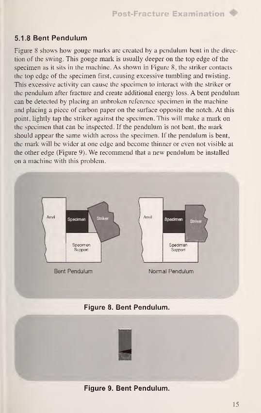
5.1.8 Bent Pendulum
Figure 8 shows how gouge marks are created by a pendulum bent in the direc-
tion of the swing. This gouge mark is usually deeper on the top edge of the
specimen as it sits in the machine. As shown in Figure 8, the striker contacts
the top edge of the specimen first, causing excessive tumbling and twisting.
This excessive activity can cause the specimen to interact with the striker or
the pendulum after fracture and create additional energy loss. A bent pendulum
can be detected by placing an unbroken reference specimen in the machine
and placing a piece of carbon paper on the surface opposite the notch. At this
point, lightly tap the striker against the specimen. This will make a mark on
the specimen that can be inspected. If the pendulum is not bent, the mark
should appear the same width across the specimen. If the pendulum is bent,
the mark will be wider at one edge and become thinner or even not visible at
the other edge (Figure 9). We recommend that a new pendulum be installed
on a machine with this problem.
Figure 8. Bent Pendulum.
Figure 9. Bent Pendulum.
15
6. Summary
The condition and accuracy of Charpy machines cannot be checked only by
comparing results of NIST reference specimens to the Master Reference
Machines located at NIST, Boulder, CO. Some machine problems cause artifi-
cially low results while other machine problems cause artificially high results.
In addition, deviations in procedures can cause similar results. These machine
problems and procedural deviations may go undetected for years without some
sort of physical check. For this reason, examination of the broken specimens is
a critical part of the verification process. Many machine problems can be
avoided or corrected with the information presented in this paper. Also, sug-
gested changes in procedure can help to ensure a successful test. To obtain
verification specimens or to clarify procedures for verification testing, you
may use the following information:
Verification specimens can be ordered from the NIST Standard Reference
Materials Program. Phone: (301) 975-6776, fax: (301) 948-3730, or email: