76
STUDY OF UNIFIED POWER QUALITY CONDITIONER FOR POWER QUALITY IMPROVEMENT RAJIV KUMAR SINKU Department of Electrical Engineering National Institute of Technology, Rourkela May 2015

STUDY OF UNIFIED POWER QUALITY
CONDITIONER FOR POWER QUALITY
IMPROVEMENT
RAJIV KUMAR SINKU
Department of Electrical Engineering
National Institute of Technology, Rourkela
May 2015
STUDY OF UNIFIED POWER QUALITY
CONDITIONER FOR POWER QUALITY
IMPROVEMENT
A Thesis Submitted to NIT Rourkela
In the Partial Fulfilment of the Requirements for the Degree Of
Master of Technology
In
Electrical Engineering
By
RAJIV KUMAR SINKU
(Roll No: 213EE5352)
Under the supervision of
Prof. P. K. RAY
Department of Electrical Engineering
National Institute of Technology, Rourkela
May 2015

ii
Dedicated to
My
Beloved Parents

iii
NATIONAL INSTITUTE OF TECHNOLOGY
ROURKELA
CERTIFICATE
This is to certify that the thesis entitled, "Study of Unified Power Quality Conditioner for
Power Quality Improvement” submitted by Rajiv Kumar Sinku (Roll No. 213EE5352) in
partial fulfilment of the requirements for the award of Master of Technology Degree in
Electrical Engineering with specialization in Industrial Electronics during 2014 -2015 at the
National Institute of Technology, Rourkela is an authentic work carried out by him under my
supervision and guidance.
To the best of my knowledge, the matter embodied in the thesis has not been submitted to any
other University / Institute for the award of any Degree or Diploma.
Place: NIT Rourkela Prof. P. K. Ray
Date: Department of Electrical Engineering
National Institute of Technology
Rourkela-769008

iv
DECLARATION
I hereby declare that the investigation carried out in the thesis has been carried out by me. The
work is original and has not been submitted earlier as a whole or in part for a degree/diploma
at this or any other institute/University.
Rajiv Kumar Sinku
Roll Number: 213EE5352

v
ACKNOWLEDGEMENTS
I would like to express my sincere gratitude to my supervisor Prof. P. K. Ray for his
guidance, encouragement, and support throughout the course of this work. It was an
invaluable learning experience for me to be one of his students. As my supervisor his
insight, observations and suggestions helped me to establish the overall direction of their
search and contributed immensely for the success of this work.
I express my gratitude to Prof. A. K. Panda, Head of the Department, Electrical
Engineering for his invaluable suggestions and constant encouragement all through this
work.
My thanks are extended to my colleagues in power control and drives, who built an
academic and friendly research environment that made my study at NIT, Rourkela most
fruitful and enjoyable.
I would also like to acknowledge the entire teaching and non-teaching staff of Electrical
department for establishing a working environment and for constructive discussions.
Finally, I am always indebted to all my family members, especially my parents, for their
endless support and love.
Rajiv Kumar Sinku
Roll Number: 213EE5352
vi
Contents
Title Pg. No.
Acknowledgements .................................................................................................................... v
Abstract ..................................................................................................................................... ix
List of figures ............................................................................................................................. x
List of tables ............................................................................................................................. xii
List of abbreviation .................................................................................................................. xii
Chapter-1: INTRODUCTION .............................................................................................. 1-6
1.1 Overview .............................................................................................................. 2
1.2 Literature Review ................................................................................................. 3
1.3 Research Motivation ............................................................................................ 5
1.4 Thesis Objective ................................................................................................... 5
1.5 Organization of thesis .......................................................................................... 5
Chapter-2: POWER QUALITY ......................................................................................... 7-17
2.1 Introduction .......................................................................................................... 8
2.2 Linear and Non- linear loads ................................................................................ 8
2.2.1 Linear load ................................................................................................... 8
2.2.2 Non-linear load ............................................................................................ 9
2.3 Major Power Quality Problems ......................................................................... 10
2.3.1 Short Duration Voltage Variation .............................................................. 10
2.3.2 Long duration voltage variation ................................................................. 11
2.3.3 Voltage Fluctuations .................................................................................. 11
2.3.4 Voltage Unbalance ..................................................................................... 12
2.3.5 Transients ................................................................................................... 12
2.3.6 Waveform Distortions ................................................................................ 13
2.3.7 Frequency Variations ................................................................................. 14
2.4 Power Definitions .............................................................................................. 14

vii
2.5 Harmonics .......................................................................................................... 15
2.6 Harmonic indices ............................................................................................... 15
2.6.1 Total harmonic distortion ........................................................................... 15
2.6.2 Total Demand Distortion ........................................................................... 15
2.7 Problems caused by harmonics .......................................................................... 16
2.7.1 Harmonics problems in installation ........................................................... 16
Chapter-3: UNIFIED POWER QUALITY CONDITIONER .......................................... 18-40
3.1 Introduction ........................................................................................................ 19
3.2 Active Power Filter ............................................................................................ 19
3.3 Basic Configuration of UPQC ........................................................................... 20
3.3.1 Operation of UPQC .................................................................................... 22
3.3.2 UPQC configuration .................................................................................. 23
3.3.3 Power flow analysis of UPQC in steady state ........................................... 24
3.4 Shunt Active Power Filter .................................................................................. 28
3.4.1 Block Diagram of shunt APF ..................................................................... 29
3.4.2 Basic structure of shunt APF ..................................................................... 30
3.4.3 Steps for controlling shunt APF ................................................................. 30
3.4.4 Control scheme of shunt APF .................................................................... 30
3.4.5 Flow chart of control scheme of shunt APF .............................................. 33
3.4.6 Hysteresis current controller ...................................................................... 33
3.4.7 PI controller ............................................................................................... 35
3.4.8 DC voltage regulator .................................................................................. 35
3.5 Series Active Power Filter ................................................................................. 35
3.5.1 Block diagram of series APF ..................................................................... 36
3.5.2 Basic structure of series APF ..................................................................... 37
3.5.3 Steps for controlling series APF ................................................................ 37
3.5.4 Control scheme of series APF .................................................................... 37

viii
3.5.5 Flow chart of series APF control techniques ............................................. 38
3.5.6 Hysteresis voltage controller ...................................................................... 38
3.5.7 Series Transformer ..................................................................................... 39
3.5.8 DC voltage regulator .................................................................................. 40
Chapter-4: RESULTS AND DISCUSSIONS .................................................................. 41-58
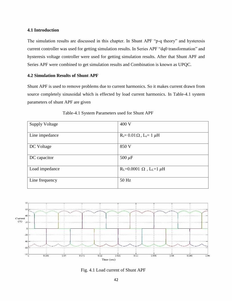
4.1 Introduction ........................................................................................................ 42
4.2 Simulation results of Shunt APF ........................................................................ 42
4.3 Simulation results of series APF ........................................................................ 45
4.3.1 Voltage across series APF during sag ........................................................ 46
4.3.2 Voltage across series APF during swell ..................................................... 47
4.4 Simulation results of UPQC ............................................................................... 48
4.4.1 Current harmonic compensation and voltage sag mitigation ..................... 49
4.4.2 Current harmonic compensation and voltage swell mitigation .................. 54
Chapter-5: CONCLUSIONS AND FUTURE WORK .................................................... 59-60
5.1 Conclusions ........................................................................................................ 60
5.2 Future Work ....................................................................................................... 60
REFERENCES ................................................................................................................. 61-63

ix
ABSTRACT
In a powers system network there are many problems related to power quality. So to improve
power quality of a system we use different devices such as active power filters. Active power
filters are classified into two types that is Shunt Active Power Filter (APF) and Series Active
Power Filter (APF) and combination of both is known as UPQC (Unified Power Quality
Conditioner). Here we have done simulation of Shunt Active Power Filter, Series Active Power
Filter and Unified Power Quality Conditioner. Shunt APF is used to mitigate the problems due
to current harmonics which is because of non-linear load and make source current sinusoidal
and distortion free. The control scheme used is hysteresis current controller using “p-q theory”.
Series APF is used to mitigate problems caused due to voltage distortion and unbalance present
in source voltage and make load voltage perfectly balanced and regulated. The control scheme
used is Hysteresis voltage controller by using a-b-c to d-q transformations. Then Shunt APF
and Series APF is combined for designing UPQC and by this current harmonics in load current
and voltage unbalances in source voltage both are removed and source current becomes
sinusoidal and load voltage becomes perfectly balanced.
x
List of Figures
Title Pg. No.
Fig.2.1: Voltage Sag ............................................................................................................... 10
Fig.2.2: Voltage swell ............................................................................................................. 10
Fig.2.3: Voltage interruption ................................................................................................... 11
Fig.2.4: Voltage Fluctuation and flicker ................................................................................. 12
Fig.2.5: Impulsive Transient ................................................................................................... 12
Fig.2.6: Oscillatory Transient ................................................................................................. 13
Fig.3.1: Active Power Filter Classifications ............................................................................ 20
Fig.3.2: Configuration of UPQC ............................................................................................. 22
Fig.3.3: Left shunt UPQC ....................................................................................................... 23
Fig.3.4: Right shunt UPQC ..................................................................................................... 24
Fig.3.5: Circuit diagram of UPQC .......................................................................................... 24
Fig.3.6: Reactive Power Flow ................................................................................................. 26
Fig.3.7: Real power flow during voltage dip (sag) condition ................................................. 26
Fig.3.8: Real power flow during voltage rise condition ......................................................... 27
Fig.3.9: Real power flow during normal condition ................................................................. 28
Fig.3.10: Basic control design of shunt APF .......................................................................... 29
Fig.3.11: Flow chart of shunt APF control technique ............................................................. 33
Fig.3.12: Hysteresis Current Controller .................................................................................. 34
Fig.3.13: Principle of hysteresis current controller ................................................................. 35
Fig.3.14: Basic control design of series APF .......................................................................... 36
Fig.3.15: Flow chart of control technique of series APF ........................................................ 38
Fig.3.16: Hysteresis Voltage Controller ................................................................................. 39
Fig.3.17: Principle of hysteresis voltage controller ................................................................. 39
Fig.4.1: Load current of shunt APF ........................................................................................ 42
Fig.4.2: Source current of shunt APF ..................................................................................... 43
xi
Fig.4.3: Injected current of shunt APF .................................................................................... 43
Fig.4.4 Capacitor voltage ........................................................................................................ 44
Fig.4.5: THD of load current .................................................................................................. 44
Fig.4.6: THD of source current after using shunt APF ........................................................... 45
Fig.4.7: Source voltage of series APF during sag ................................................................... 46
Fig.4.8: Load voltage of series APF during sag ...................................................................... 46
Fig.4.9: Voltage injected by series APF ................................................................................. 47
Fig.4.10: Source voltage during swell .................................................................................... 47
Fig.4.11 Load voltage during swell ........................................................................................ 48
Fig.4.12 Injected voltage during swell .................................................................................... 48
Fig.4.13: Source voltage during sag of UPQC ....................................................................... 49
Fig.4.14: Load voltage of UPQC during sag .......................................................................... 50
Fig.4.15: Injected voltage of UPQC during sag ..................................................................... 50
Fig.4.16: Load current of UPQC during sag ........................................................................... 51
Fig.4.17: Source current of UPQC during sag ........................................................................ 51
Fig.4.18: Injected current of UPQC during sag ...................................................................... 52
Fig.4.19: Capacitor voltage across UPQC .............................................................................. 52
Fig.4.20: THD of load current of UPQC during sag ............................................................... 53
Fig.4.21 THD of source current of UPQC sag ........................................................................ 53
Fig.4.22 Source voltage of UPQC during swell ..................................................................... 54
Fig.4.23: Load voltage of UPQC during swell ....................................................................... 54
Fig.4.24: Injected voltage of UPQC during swell ................................................................... 55
Fig.4.25: Load current during swell of UPQC ........................................................................ 55
Fig.4.26: Source current of UPQC during swell ..................................................................... 56
Fig.4.27: Injected current of UPQC during swell ................................................................... 56
Fig.4.28: Capacitor voltage during swell ................................................................................ 57
Fig.4.29: THD of load current during swell ........................................................................... 57
xii
Fig.4.30: THD of source current during swell ........................................................................ 58
List of Tables
Title Pg. No.
Table 2.1: Examples of Linear Loads ....................................................................................... 9
Table 2.2: Examples of Non-Linear Loads ............................................................................... 9
Table 4.1: System parameters used for Shunt APF ................................................................ 42
Table 4.2: System parameters used for series APF ................................................................. 45
Table 4.3: System parameters used for UPQC ....................................................................... 49
List of Abbreviation
APF Active Power Filter
FFT Fast Fourier Transform
DSTATCOM Distribution Static Compensator
DVR Dynamic Voltage Regulator
HB Hysteresis Band
LPF Low Pass Filter
HPF High Pass Filter
PCC Point of Common Coupling
PLC Programmable Logic Controller
PLL Phase Locked Loop
THD Total Harmonic Distortion
UPQC Unified Power Quality Conditioner
VSI Voltage Source Inverter
CSI Current Source Inverter
UVT Unit Vector Template
1
Chapter 1
INTRODUCTION
1.1 Overview
1.2 Literature Review
1.3 Research Motivation
1.4 Thesis Objective
1.5 Organization of Thesis
2
1.1 Overview In today’s world there is great importance of electrical energy as it is the most famous from of
energy and all are massively relying on it. Without supply of electricity life cannot be imagined.
At the same time the quality and continuousness of the electric power supplied is also very
important for the efficient functioning of the end user equipment. Many of the commercial and
industrial loads require high quality undisturbed and constant power. Thus maintaining the
qualitative power is topmost important in today’s world.
Due to power electronics devices there is serious effect on quality and continuousness of electric
supply. Because of power electronics devices there is uninterrupted power supply, flicker,
harmonics, voltage fluctuations e.tc. There is also PQ problems such as voltage rise/dip due to
network faults, lightning, switching of capacitor banks. With the excessive uses of non-linear load
(computer, lasers, printers, rectifiers) there is reactive power disturbances and harmonics in power
distribution system. It is very essential to overcome this type of problems as its effect may increase
in future and cause adverse effect.
Traditionally passive filters were used for reactive power disturbances and harmonics generation
but there is many problems with them like they are large in size, resonance problem, effect of
source impedance on performance.
Active Power Filters are used for power quality enhancement. Active power filters can be
classified according to system configuration. Active power filters are of two types series and shunt.
Combining both series APF & shunt APF we get a device known as UPQC. UPQC eliminates the
voltage and current based distortions together.
A Shunt APF eliminates all kind of current problems like current harmonic compensation, reactive
power compensation, power factor enhancement. A Series APF compensates voltage dip/rise so
that voltage at load side is perfectly regulated. The Shunt APF is connected in parallel with
transmission line and series APF is connected in series with transmission line. UPQC is formed
by combining both series APF and shunt APF connected back to back on DC side.
In this controlling techniques used is hysteresis band controller using “p-q theory” for shunt APF
and hysteresis band controller using Park’s transformation or dq0 transformation for series APF.
UPQC is made by combining both shunt APF and series APF. UPQC is used to eliminate all
problems due to current harmonics and voltage unbalances & distortions and improve power
quality of a system. UPQC is a very versatile device as at same time it mitigates the problem both
3
due to current and voltage harmonics. In this thesis power quality of system was improved by
using UPQC. First simulation of shunt APF was done after that series APF was done. And after
that combining both device simulation of UPQC was done.
1.2 Literature Review
Now a day’s power quality has become the most essential factor for both power suppliers and
consumers due to the degradation of the electric power energy market. Efforts are being made to
improve power quality. Today in this modern world power quality has become a great issue. As
many industries and for domestics use we need a voltage and current free from all types of
harmonics and unbalances. Due to problems in power quality there is development of many
methods to improve power quality by using active power filters [1] [2]. The concept of power was
introduced by the N.G. Hingrani [3]. Power electronics devices consists of a diode, thyristors,
IGBT, diodes [4]. The active power filters are used to remove harmonics from current of load side
and make supply current completely sinusoidal, and it also mitigate the problems of supply voltage
imbalance i.e voltage rise/dip and make voltages at load side balanced of equal magnitude. The
active power filters can be combined together and made to remove both problems due to voltage
and current harmonics. There are wide range of controlling techniques for active power filters [5].
The [6] reactive power theory was used to do simulation of three phase three wire line
which is valid for both of the transient and steady state. The physical meaning of instantaneous
reactive power theory was described in [7]. The instantaneous reactive power theory with the non-
linear loads is described in [8]. The DVR model is discussed in [9] for removal of all kinds of
voltage related problems. Here the operating system consist of PLL and Park’s transformation is
used for simulation. In [10] three phase simulation of series active power filter is done for removal
of voltage unbalances in supply side and make load voltage balanced and regulated. In chapter
[11] the operation of DSTATCOM is explained. In [12] the operation of three phase four wire
shunt APF is explained which is used to suppress load current harmonics which is due to non-
linear loads. As the power quality is the most important factor so to get improved power quality
and removal of all type of harmonics from voltage and current we study UPQC which is a very
versatile device and can be used for both mitigate the problems due to current harmonics and
voltage disturbances [13]. The voltage source inverter active filters are used for removal of power
quality problems [14] [15]. The shunt active power filer is used to remove all the problems related
to current harmonics and reactive power compensation so that the power quality will improve and

4
source current will become completely sinusoidal, it is also used for power factor correction [16].
A series APF removes all kind of problems which arises due to voltage like voltage distortion,
fluctuations, voltage dip/rise and make load side voltage balanced and equal in magnitude. [17].
A UPQC is a device which is formed by connecting a series APF and shunt APF back to back
through DC capacitor [18]. This vast range of objectives is achieved either individually or in
combination, depending upon the requirements and controlling techniques and configuration
which have to be selected appropriately [19]. In [20] UPQC control techniques are introduced for
removal of harmonics. A unit vector template generation is explained in this paper. In [21] UPQC
control strategy was discussed for three phase four wire system, here series APF and shunt APF
are connected back to back with the help of DC capacitor and unit vector template control strategy
was used for series APF. In [22] a new control strategy for UPQC was discussed for removal of
harmonics under non-ideal mains voltage and unbalanced loads. The power quality is improved
near PCC (point of common coupling). In [23] a unified quality conditioner was developed for
both removal of harmonics and reactive p16wer compensation. UPQC was studied with both R-L
load and R-C load. Here the PI controller were used to get the amount of power loss in the UPQC.
As we know that in today’s world due to non-linear loads which is because of power electronics
devices and due to faults in the power systems there arises many power quality problems so to
remove this problems we use different types of filters. Earlier passive filters were used but because
of their larger size and resonance problems the use of passive filters are not recommended. So now
a days active power filters are used, which are classified according to different methodology. But
our main consideration in Shunt APF, Series APF, and UPQC. A UPQC is most efficient device
as it removes all kind of problems related to power quality. But Shunt APF only operates for
current related problems whereas series APF operates for voltage related problems. So UPQC is
the device mainly used for power quality problem. There are many control techniques used for
shunt APF, series APF and UPQC. For shunt APF we can use “p-q theory” and hysteresis current
controller. Also we can use Park’s transformation that is dq0 theory. There is also SPWM
techniques used for shunt APF simulation. For series APF control techniques used is Park’s
transformation and hysteresis voltage controller. Also we can use SPWM techniques and SVPWM
(space vector pulse width modulation) technique for series APF.
For UPQC control technique used in this thesis is hysteresis controller.
5
1.3 Research motivation
Due to increase in use of power electronics devices in the power system and due faults in the
system the electric power supply gets interrupted and power quality is highly effected. There is
contents of harmonics in currents and voltages. There are faults like flicker, increase in voltage
fluctuations. The telecommunication, industries, and semiconductor manufacturing industries are
more sensitive to power quality problems as they need high quality of power. So here we have
studied how to remove power quality problems with the help of active power filters. Shunt APF is
used to compensate the problems caused by load current harmonics and make the source current
completely sinusoidal. Series APF is used to mitigate problems related to voltage dip/rise in source
voltage and make load voltage completely regulated. UPQC is used to solve all problems related
to voltage and current harmonics and improve power quality.
1.4 Thesis Objective
The objective of this project are
To explore the techniques for removal of current harmonics and mitigate the voltage swell,
sag.
Study the UPQC model for power quality improvement.
Investigate Shunt APF for compensating load current harmonics and so that current drawn
from supply is completely sinusoidal.
Investigate Series APF so to mitigate voltage dip and rise from source voltage and make
load voltage perfectly balanced.
1.5 Organization of Thesis
In Chapter 1 there is brief description about the thesis and paper studied for organization of thesis
and the summary of work done by different researchers and how I was motivated to do this project,
and objective of thesis.
In Chapter 2 there is a discussion about power quality, and what are the problems effecting power
quality of a system, different types of loads, harmonics indices.
In Chapter 3 there is discussion about UPQC, different control strategy of UPQC, parts of UPQC
i.e. Shunt APF and series APF. And different control strategy required for simulation of both.
6
In Chapter 4 simulation results are given and they are discussed.
In Chapter 5 conclusions are discussed along with future scope and references.
7
Chapter 2
POWER QUALITY
2.1 Introduction
2.2 Linear and Non-Linear Loads
2.3 Major Power Quality Problems
2.4 Power Definitions
2.5 Harmonics
2.6 Harmonics Indices
2.7 Problems Caused by Harmonics
8
2.1 Introduction In our day to day life, and in many industries there is very huge use of power electronics devices,
Programmable logic circuits (PLC), semiconductor devices, and adjustable speed drives due to
this there is power quality problems. There is also many external and internal factors that effect
the quantity and quality of power delivered. Many network faults, switching of capacitor banks,
voltage sag/swell, lightning, and harmonics also cause power quality problems. Mainly loads work
at 50 Hz and 60 Hz frequencies. But there are many loads which work at integer multiple of 50 Hz
and 60 Hz frequencies. Because of these loads there is harmonics in power system.
2.2 Linear and Non- linear loads
2.2.1 Linear load
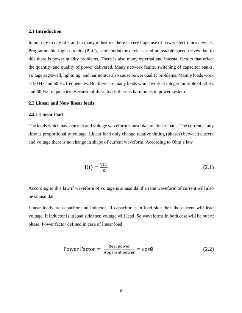
The loads which have current and voltage waveform sinusoidal are linear loads. The current at any
time is proportional to voltage. Linear load only change relative timing (phases) between current
and voltage there is no change in shape of current waveform. According to Ohm’s law
I(t) =V(t)
R (2.1)
According to this law if waveform of voltage is sinusoidal then the waveform of current will also
be sinusoidal.
Linear loads are capacitor and inductor. If capacitor is in load side then the current will lead
voltage. If inductor is in load side then voltage will lead. So waveforms in both case will be out of
phase. Power factor defined in case of linear load
Power Factor = Real power
Apparent power= cos∅ (2.2)
9
Examples of linear loads are given in Table 2.1
Table 2.1 Examples of linear load
Resistive components Inductive components Capacitive components
Lightning
Heaters
Incandescent
Lamps
Induction motors
Induction generators
(windmills)
Insulated cables
Underground cables
Capacitors used in
harmonic filters
2.2.2 Non-Linear loads
In non-linear loads the shape of current waveform changes its shape from original shape. Non-
linear loads produces harmonics with original fundamental component of AC current. Non-linear
loads examples are power electronics devices like BJT, MOSFET. Given in Table 2.2
Table 2.2 Examples of non- linear load
Power Electronics ARC devices
Power converters
Inverters
Cranes
Computers
UPS
Refrigerators
Battery chargers
Elevators Steel mills
Power supplies
ARC furnaces
Welding machines
10
2.3 Major power quality problems
2.3.1 Short duration voltage variation
Due to faults there is voltage rise (swells), voltage dip (sag), or complete loss of voltages
(interruptions) which are temporary for certain interval of time depending upon the type of fault
occurred and location of fault. The duration is around 1 min for short voltage variation. Also if
duration of fault is for few millisecond then it is short duration voltage variation.
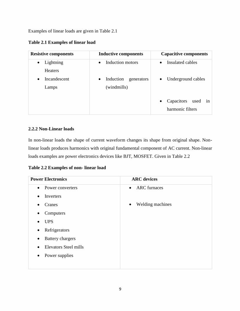
(i) Voltage sag:- Voltage sag is also called voltage dip . The rms line voltage decreases to 10 %
to 90 % of nominal line voltage. The time interval for voltage dip is about 0.5 cycle to 1 min. The
equipment which cause voltage dip are induction motor starting etc. Voltage dip is shown in fig.2.1
Fig.2.1 Voltage sag
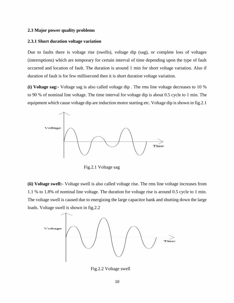
(ii) Voltage swell:- Voltage swell is also called voltage rise. The rms line voltage increases from
1.1 % to 1.8% of nominal line voltage. The duration for voltage rise is around 0.5 cycle to 1 min.
The voltage swell is caused due to energizing the large capacitor bank and shutting down the large
loads. Voltage swell is shown in fig.2.2
Fig.2.2 Voltage swell
11
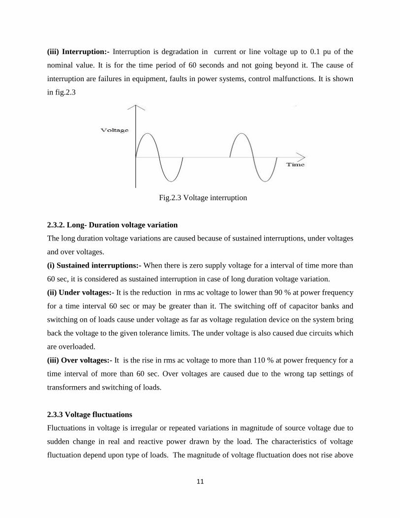
(iii) Interruption:- Interruption is degradation in current or line voltage up to 0.1 pu of the
nominal value. It is for the time period of 60 seconds and not going beyond it. The cause of
interruption are failures in equipment, faults in power systems, control malfunctions. It is shown
in fig.2.3
Fig.2.3 Voltage interruption
2.3.2. Long- Duration voltage variation
The long duration voltage variations are caused because of sustained interruptions, under voltages
and over voltages.
(i) Sustained interruptions:- When there is zero supply voltage for a interval of time more than
60 sec, it is considered as sustained interruption in case of long duration voltage variation.
(ii) Under voltages:- It is the reduction in rms ac voltage to lower than 90 % at power frequency
for a time interval 60 sec or may be greater than it. The switching off of capacitor banks and
switching on of loads cause under voltage as far as voltage regulation device on the system bring
back the voltage to the given tolerance limits. The under voltage is also caused due circuits which
are overloaded.
(iii) Over voltages:- It is the rise in rms ac voltage to more than 110 % at power frequency for a
time interval of more than 60 sec. Over voltages are caused due to the wrong tap settings of
transformers and switching of loads.
2.3.3 Voltage fluctuations
Fluctuations in voltage is irregular or repeated variations in magnitude of source voltage due to
sudden change in real and reactive power drawn by the load. The characteristics of voltage
fluctuation depend upon type of loads. The magnitude of voltage fluctuation does not rise above
12
10% of nominal supply voltages. The Lamp flicker is the effect of voltage fluctuations. Loads that
cause fluctuations in voltages are arc furnaces, arc welders, air conditioner units, rolling mills,
cycloconverters, and equipment with excessive motor speed changes. Voltage fluctuations are
shown in fig.2.4
Fig.2.4 Voltage fluctuation and flicker
2.3.4 Voltage Unbalance
Voltage unbalances occur when there is difference in magnitude of phases or line voltages and
phase angle is different from balanced conditions. Voltage unbalance is due to different loads in
the phases causing drops in voltages at phase – line impedance.
2.3.5 Transients
Transients are sudden & small change in current and voltage signals for a very less period of time.
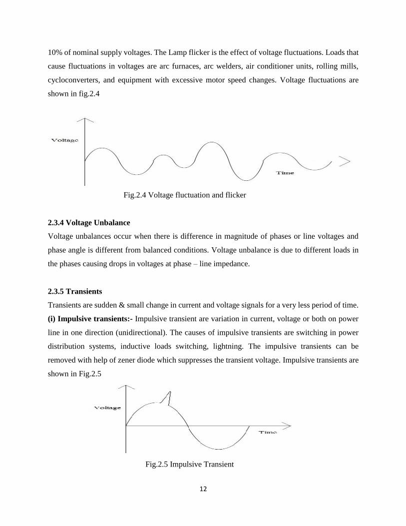
(i) Impulsive transients:- Impulsive transient are variation in current, voltage or both on power
line in one direction (unidirectional). The causes of impulsive transients are switching in power
distribution systems, inductive loads switching, lightning. The impulsive transients can be
removed with help of zener diode which suppresses the transient voltage. Impulsive transients are
shown in Fig.2.5
Fig.2.5 Impulsive Transient

13
(ii) Oscillatory transients:- Oscillatory transients are transients which have swing (bidirectional)
i.e. rapid change of polarity of current , voltage or both on power line. Causes of this is Capacitors
switching which help in power factor correction. It is given in fig.2.6
Fig.2.6 Oscillatory Transient
2.3.6 Waveform Distortion
A power system network tries to generate a sinusoidal voltage and current waveform but due to
certain problem it is not able to generate the sinusoidal nature waveform and distortions occurs.
There are many causes of waveform distortion:-
(i) DC Offset:- A DC offset is a presence of DC voltage or current in a AC power system. Due to
DC offset the signal shifts from its actual reference position.
(ii) Noise:- Noise is unwanted electrical signals. It is caused due to interference in communication
network. The unwanted signals are superimposed in powers system current or voltage which are
in phase or in neutral conductors.
(iii) Notching:- Notching is voltage disturbances caused periodically due to transfer of current
from one phase to another when power electronics equipment are commutated.
(iv) Harmonics:- The harmonics are sinusoidal currents and voltages which operate at frequencies
that are integer multiple of fundamental frequency. The 50 Hz and 60 Hz are fundamental
frequency. The harmonics are caused due to non- linear loads. Total harmonic distortion (THD) of
voltage is measured by

14
VTHD =√∈n=2
∞ Vn2
V1 (2.3)
Where V1 is rms magnitude of fundamental component & Vn is rms magnitude of component
when n= 2…….. ∞.
(v) Inter harmonics:- Inter harmonics are harmonics which are not at the frequencies that are
integer multiple of fundamental frequency (50 Hz or 60 Hz). That are caused due to induction
furnaces, cycloconverters, arc furnaces, static frequency converters.
2.3.7 Frequency variations
In a power system many equipment and devices are made to operate at fundamental frequency.
But there is variations in frequency due sudden disturbances in supply or demand. Frequency
variations are mainly caused due to failure of generators and switching of loads.
2.4 Power definitions
Definitions of apparent power, active power, reactive power, complex power, power factor are
given below:-
(i) Apparent power:- It is multiplication between rms voltage & rms current in circuit. It is given
by
S = Vrms × Irms (2.4)
Where Vrms = √1
T∫ v2(t)dt
T
0= √∈k=1
∞ Vk2 (2.5)
Irms = √1
T∫ i2(t)dt
T
0= √∈k=1
∞ Ik2 (2.6)
Here Vk and Ik are rms value of kth order harmonic component of Fourier series and T is time
period of fundamental component.
(ii) Active power:- It is the real power drawn by the circuit while doing any useful work. It is
measured in watts.
P =∈k=1∞ Pk =∈k=1
∞ VkIk cos∅k (2.7)
here ∅𝑘 is displacement angle of each pair kth order harmonic component of current & voltage.
15
(iii) Reactive power:-It is energy stored and discharged by capacitors, induction motor,
transformers etc. . It is measured in volt-ampere reactive (VAR).
Q =∈𝑘=1∞ 𝑄𝑘 = ∈𝑘=1
∞ 𝑉𝑘𝐼𝑘 sin∅𝑘 (2.8)
2.5 Harmonics
Harmonics are sinusoidal voltage & current which operate at integer multiple of fundamental
frequency.
2.6 Harmonics indices
In power Quality Corporation some index values has been developed to determine the service
quality and distortions caused due to harmonics. The two indexes mostly used are total harmonic
distortions (THD) and total demand distortion (TDD). Harmonics indices are given below:-
2.6.1 Total harmonic distortion (THD):
The THD of a signal is measurement of harmonic distortion present in it. Low THD means there
is reductions in heating, losses, and peak currents in a power systems. THD is measured in
percentage. THD is given as
THD =rms value of all harmonic component of a signal
rms value of fundamental component (2.9)
THD = √(Y2+Y3+⋯………………+ YH )
Y1 (2.10)
Here H is the order of harmonic component and Y1 is the fundamental component of signal.
2.6.2 Total Demand Distortion (TDD):
It is described as root sum square value of harmonic current to maximum demand load current.
When TDD is calculated rather than THD in a system than there is comparing between actual load
of the system to the maximum load which avoid the end customer from unreasonably penalized
when load is lighter than maximum load.
TDD = √sum of squares of amplitude of all harmonics
square of maximim demad load current × 100% (2.11)

16
𝑇𝐷𝐷 = √∈H=2
Hmax. IH2
IL (2.12)
Here IL is maximum demand load current at the point of common coupling (PCC) and H is the
order of harmonic component of current.
2.7 Problems caused by harmonics
Due to harmonics there is problems in supply system and also in the installation and user ends and
also. There are many problems caused due to harmonics
2.7.1 Harmonics problems in an installation
Problems due to Current harmonics:
(i) Transformers overheating:- Due to harmonic current there is heating in transformers this is
mainly because of two reasons:-
Due to harmonic current the rms current of transformer increases more than its capacity
causing losses.
Harmonic current component increases eddy current losses as it is directly proportional to
square of frequency.
(ii) Skin effect:-The phenomenon of alternating current to flow at exterior surface of conductor is
known as skin effect. Due to harmonics current the skin effect is more as skin effect increases with
increase in frequency. Skin effect is normal at fundamental frequency but it increases as frequency
increases and due to harmonics frequency increases.
(iii) Neutrals overloading:-The voltage waveform in three phase system has 1200 angle displaced
between phase and neutral. When loads are unbalanced a net balance current flows in neutral. Due
to harmonics there is addition of current in neutral but balanced current cancel outs.
(iv) Circuit Breaker Tripping:-Circuit breakers operate by adding the current of phases & neutral
conductors, if the current is not within the limit it disconnects the load from circuit. Due to
harmonics tripping can occur.
17
Problems due to voltage harmonics:-
(i) Distortion in voltages:-There is distorted voltage drop in transmission line because of
transmission line impedance which is caused because of distorted load current which is due to non-
linear loads.
(ii) Induction Motors:- Due to harmonic voltage distortion there is eddy current losses in motors
same as transformers. Also due to harmonics there is stator losses etc.
18
Chapter 3
UNIFIED POWER QUALITY CONDITIONER
3.1 Introduction
3.2 Active Power Filter
3.3 Basic Configuration of UPQC
3.4 Shunt Active Power Filter
3.5 Series Active Power Filter
19
3.1 Introduction
Basically UPQC (Unified Power Quality conditioner) is a equipment which is used for compensate
for voltage distortion and voltage unbalance in a power system so that the voltage at load side is
completely balance and sinusoidal & perfectly regulated and also it is used to compensate for load
current harmonics so that the current at the source side is perfectly sinusoidal and free from
distortions and harmonics. UPQC is a combination of a Shunt Active power filter and Series Active
power filter. Here Shunt Active power filter (APF) is used to compensate for load current
harmonics and make the source current completely sinusoidal and free from harmonics and
distortions. Shunt APF is connected parallel to transmission line. Here Series APF is used to
mitigate for voltage distortions and unbalance which is present in supply side and make the voltage
at load side perfectly balanced, regulated and sinusoidal. Series APF is connected in series with
transmission line. UPQC consists of two voltage source inverters connected back to back through
a DC link capacitor in a single phase, three phase-three wire, three phase-four wire configuration.
The inverter in shunt APF is controlled as a variable current source inverter and in series APF is
controlled as a variable voltage source inverter. Earlier passive filters where also used for
compensation of harmonics and voltage distortion but due to their many disadvantages they are
not used nowadays.
3.2 Active Power Filter
Traditionally passive filters were used for power quality improvement, the passive filters consists
of combination of capacitor, inductor and resistor. Passive filters are used for harmonic filtering.
Passive filters doesn’t depend upon the external power source. It has many drawbacks such as it is
larger in size, resonance problem, effect of source impedance on performance, fixed compensation
characteristics. So active power filters (APF) came as alternate solution for passive filters. Active
power filters removes harmonics and not have drawbacks such as passive filters. Active power
filters are classified as are shown in fig.3.1
20
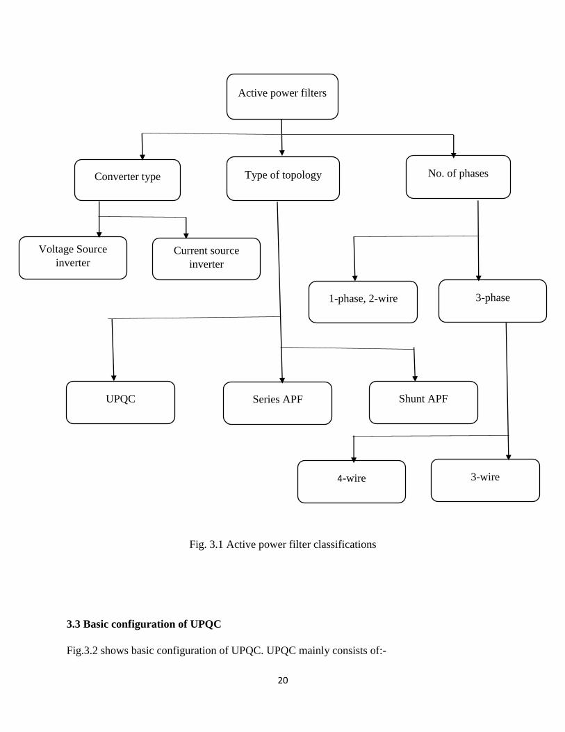
Fig. 3.1 Active power filter classifications
3.3 Basic configuration of UPQC
Fig.3.2 shows basic configuration of UPQC. UPQC mainly consists of:-
Active power filters
Converter type Type of topology No. of phases
4-wire
Series APF Shunt APF
3-wire
Voltage Source
inverter
UPQC
Current source
inverter
1-phase, 2-wire 3-phase

21
Series APF:- In a transmission line series APF is generally connected in series. It is
connected to the transmission line with the transformer. Series APF is a voltage source
inverter connected in series with transmission line. It is used to compensate or mitigate the
problems which comes due to voltage distortions and voltage unbalances. The series APF
injects a compensating voltage so that load voltage will be perfectly balanced and
regulated. Controlling of series inverter is done by PWM (pulse width modulation)
techniques. Here we used Hysteresis band PWM techniques as it implementation is easy.
Also its response is fast. Its details are explained in subsequent sections.
Shunt APF: - In a transmission line shunt APF is generally connected in parallel. Shunt
APF is used to compensate for distortions & harmonics which are produced due to current.
Due to non- linear load there is harmonics in load current, so to keep source current
completely sinusoidal and distortion free we uses Shunt APF. Shunt APF injects
compensating current so that the source current is completely sinusoidal and free from
distortions. Controlling of Shunt APF is done by hysteresis band PWM techniques. In
hysteresis band PWM techniques output current follows the reference and current and is
within the fixed hysteresis band.
Series Transformer:- The necessary voltage which is generated by series APF so that the
voltage at load side is perfectly balanced and regulated i.e. Sinusoidal is injected into the
transmission line with the help of these transformers. The series transformer turns ratio
should be suitable so that injected voltage is suitable such that it injects a compensating
voltage which will completely make the load side voltage balanced and also it reduces the
current flowing through series inverter.
Low Pass Filter:- Low pass filter is used at the output of series inverter so that the high
frequency voltage components are removed which is produced due to switching of Voltage
source inverter
High pass filter:- High pass filter is used at output of shunt inverter so that the ripples
which are produced due to currents switching are absorbed.

22
DC link capacitor:- The two voltage source inverter are connected back to back through
a DC capacitor. DC capacitor is provides a DC voltage for working of both the inverter.
The DC capacitor also provides a real power difference between source and load during
the transient period and also acts as a energy storage elements. During steady state real
power supplied by source should be equal to the sum real power demand of load & a small
amount of power which compensates for active filter. DC capacitor voltage should be
equal to reference value but due to disturbance in real power balance between source and
load due to change in load conditions the DC capacitor value is changed from reference
value.
Fig 3.2 Configuration of UPQC
3.3.1 Operation of UPQC:-
As given in fig.3.2 vs is source voltage, vc is series compensation voltage, is =source current & iL
is load current. The source voltage contains a positive, negative & zero & also the harmonic
components. The voltage at M is written as
23
𝑣𝑠 = 𝑣1𝑛(𝑡) + 𝑣1𝑝(𝑡) +∈𝑘=2∞ 𝑣𝑘(𝑡) (3.1)
Eqn (3.1) can also written as
𝑣𝑠 = 𝑣1𝑛(sin(𝑤𝑡 + 𝜃1𝑛)) + 𝑣1𝑝(sin(𝑤𝑡 + 𝜃1𝑝)) +∈𝑘=2∞ 𝑣𝑘(𝑘𝑤𝑡 + 𝜃𝑘) (3.2)
Here v1n, v1p. are fundamental frequency of component of negative sequence and positive
sequence. And vk is the harmonic component & 𝜃1𝑛, 𝜃1𝑝, 𝜃𝑘 are phase angle of voltages.
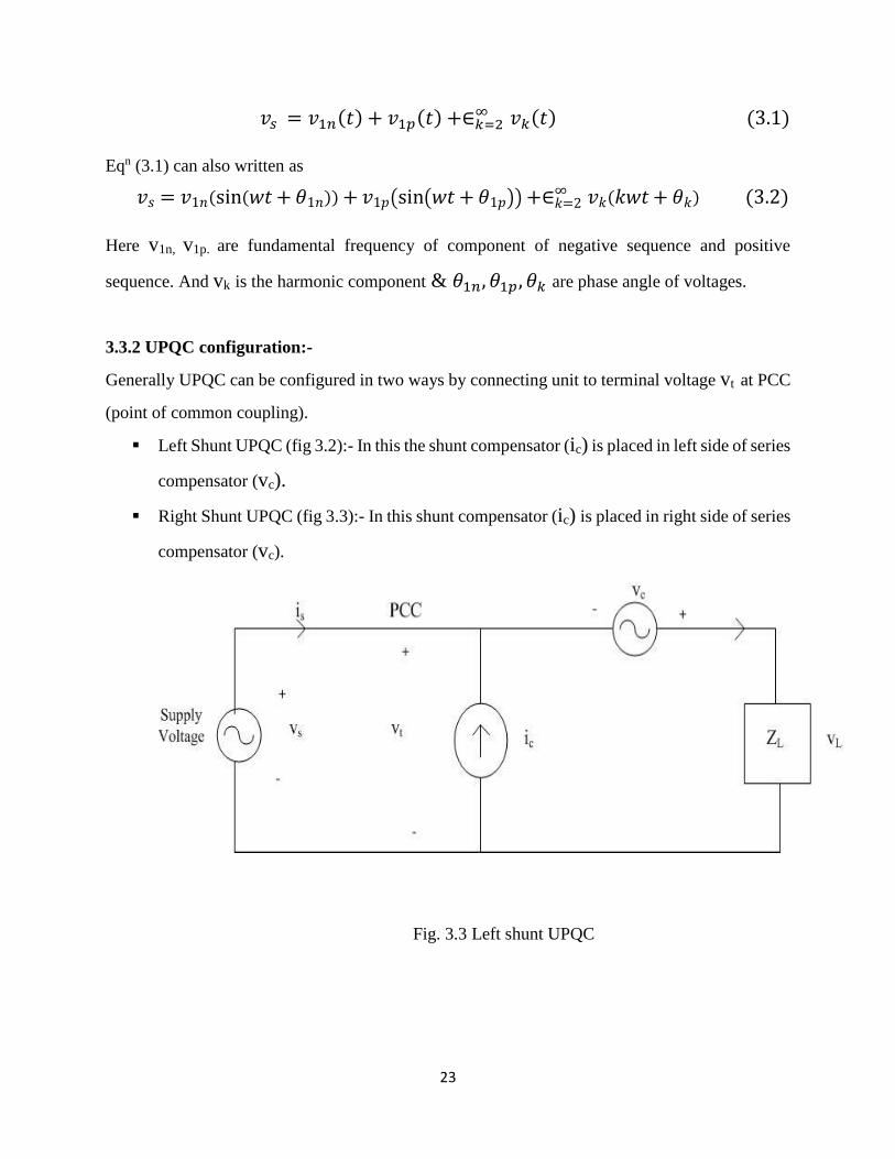
3.3.2 UPQC configuration:-
Generally UPQC can be configured in two ways by connecting unit to terminal voltage vt at PCC
(point of common coupling).
Left Shunt UPQC (fig 3.2):- In this the shunt compensator (ic) is placed in left side of series
compensator (vc).
Right Shunt UPQC (fig 3.3):- In this shunt compensator (ic) is placed in right side of series
compensator (vc).
Fig. 3.3 Left shunt UPQC

24
Fig 3.4 Right Shunt UPQC
As shown in the fig. 3.4 Right shunt UPQC has better performance than left shunt UPQC so
generally Right shunt UPQC is used.
3.3.3 Power flow analysis of UPQC in steady state
Fig. 3.5 Circuit diagram of UPQC
Here vs = source voltage

25
is = source current
vt = terminal voltage at PCC
vL = load voltage
iL = load current
ic = compensating current of shunt APF
vc = injected voltage by series APF
rs & Ls = resistance and inductance of source
k = source voltage fluctuation; k =vt−vL
vL
Circuit Diagram of UPQC is given in fig. 3.5. UPQC is used to eliminate harmonics present in
current and distortions of voltage and is used for reactive power compensation. In UPQC series
APF is used as voltage source inverter to compensate for voltage distortions and make voltage at
load side completely balanced and sinusoidal. Series APF injects a voltage which is difference of
source voltage and perfectly balanced load voltage. Shunt APF is used as to eliminate harmonics
present in load current so that source current is completely sinusoidal and also used for
compensation of reactive power. Shunt APF is also used to maintain value of DC link capacitor
constant.
Case 1
During normal operations when UPQC is disconnected from supply the reactive power is
completely supplied from the main source. But when UPQC is joined with the system than the
reactive power is supplied with the Shunt APF. Shunt APF provides reactive power to the load and
there is no burden on main supply. Series APF has no relation with reactive power demand of load.
(a) Without UPQC
Supply Load
Qs
QL

26
Load
(b) With UPQC having Shunt APF
Shunt APF
Fig.3.6 (a)-(b) Reactive power flow
Here Qs = reactive power of source
QL= reactive power of load
Qsh = reactive power of shunt APF
Case 2
Here k<0, that is vt < vL, in this case series APF is used to supply real power to load. This is the
voltage dip (sag) condition here is will be higher than normal current. In this required power is
taken from source at increased current so that power will be balanced in the network and DC
capacitor value should be at desired level. Here series injected power will be positive.
Fig. 3.7 Real power flow during Voltage dip (sag) condition
Qsh
QL
27
Here Ps” = power supplied form the source to load during voltage sag condition.
Psr” = series APF injected power
Psh” = shunt APF absorbed power during voltage dip condition
Psr” = Psh”
From source to Shunt APF the real power flows, first real power flow from source to shunt APF
and then from shunt APF to series APF through DC link capacitor and from Series APF to load.
So load will get desired power during voltage sag condition. In this case the real power absorbed
by shunt APF from source is equal to real power supplied by series APF to load. It is given in fig.
3.7.
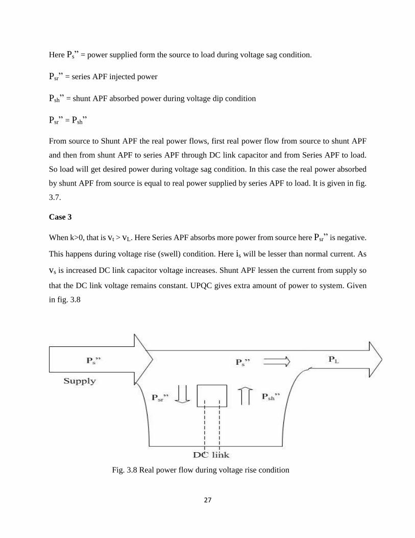
Case 3
When k>0, that is vt > vL. Here Series APF absorbs more power from source here Psr” is negative.
This happens during voltage rise (swell) condition. Here is will be lesser than normal current. As
vs is increased DC link capacitor voltage increases. Shunt APF lessen the current from supply so
that the DC link voltage remains constant. UPQC gives extra amount of power to system. Given
in fig. 3.8
Fig. 3.8 Real power flow during voltage rise condition

28
Here Ps” = power supplied form the source to load during voltage rise condition.
Psr” = series APF injected power; such that Ps”- Psr”=required voltage by load during normal
condition
Psh” = shunt APF delivered power during voltage rise condition
Psr” = Psh”
Case 4
If k=0, that is vt = vL. In this case no real power flow through UPQC and it is normal condition of
operation. Given in fig. 3.9
Fig 3.9 The real power flow in normal condition
3.4 Shunt Active Power Filter
Active power filters are devices which generates the same amount of harmonics which are
generated by load but at 1800 phase shifted. Active power filters are devices such as amplifiers etc.
Shunt APF injects the compensating current in the line at the point of common coupling (PCC) so
that the current at source sides become completely sinusoidal and free from distortions. Generally
29
due to presence of non-linear load there is harmonics & distortions in load current due to which
source current also get effected and source current becomes non-sinusoidal and distorted. So to
remove this non-sinusoidal behavior of source current we use Shunt APF which provides the
compensating current which is same as harmonic generated by load but 1800 phase shifted and this
compensating current is given at PCC which helps in removing distortions from source current
and makes source current completely sinusoidal. Shunt APF is also used for reactive power
compensation & it also removes all problems which arises due to current harmonics.
The control scheme used in Shunt APF is instantaneous reactive power theory also known as “p-
q theory”. p-q theory is used to generate the reference current and this reference current is given
to Hysteresis current controller along with compensating current (actual output current) of Shunt
APF. Hysteresis current controller is used to generate gating signal which is then given to voltage
source inverter.
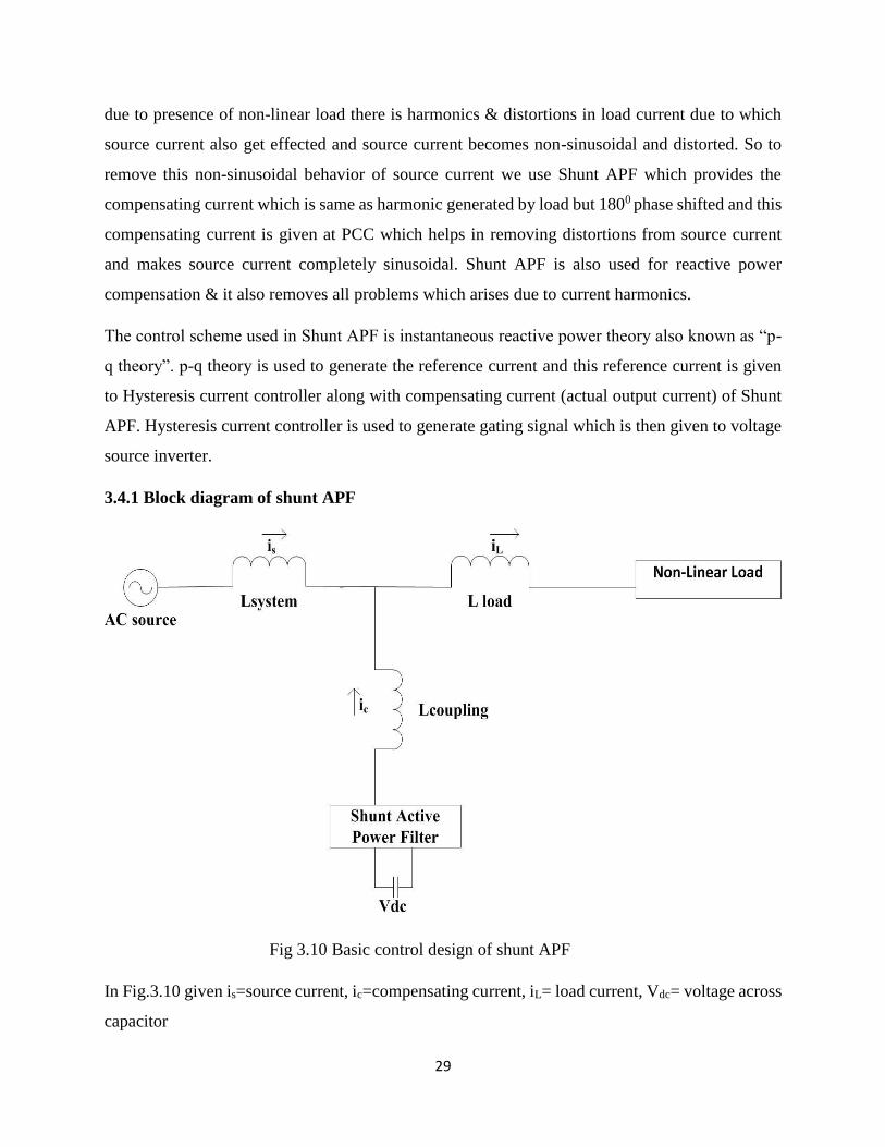
3.4.1 Block diagram of shunt APF
Fig 3.10 Basic control design of shunt APF
In Fig.3.10 given is=source current, ic=compensating current, iL= load current, Vdc= voltage across
capacitor

30
3.4.2 Basic Structure of Shunt APF
Basic structure of shunt APF consists of:-
(i) DC capacitor:- It is an energy storage device which provide real power difference
between source and load during transient periods.
(ii) Voltage source inverter:- VSI is a solid state device like IGBT, GTO etc. It is used to
inject compensating current so that the harmonics present in the load current are
removed and harmonics doesn’t affect source current. And the current taken from
source is completely sinusoidal. The PWM signal is given to VSI for its operation.
(iii) Hysteresis Current Controller:- Hysteresis current controller is used to generate
PWM signal for operation of VSI. The PWM signal is obtained by the error which we
get from comparing the reference current with the actual current.
(iv) PI controller:- PI controller is used to reduce steady state error. IT is also used to
calculate Ploss.
3.4.3 Steps for controlling shunt APF
(i) Generation of reference compensating current
(ii) Generation of gating signal by hysteresis current controller
3.4.4 Control scheme of shunt APF
Control pattern used in shunt APF is instantaneous reactive power theory which is also known as
“p-q theory”. It was introduced by Akagi et al in 1983. The instantaneous reactive power theory is
based on time domain transformations, here abc phases are transformed into αβ0 coordinates. The
coordinate 0 corresponds to a zero sequence component. “p-q theory” corresponds to a algebraic
transformations which is known as Clarke’s transformation. Advantages of “p-q theory” it is
simple as it only requires algebraic operations. It is applicable for steady state and transient state
operation. In this theory abc phases are converted to 𝛼𝛽0 are given below:-
Instantaneous reactive power theory
Clarke’s transformation is given below
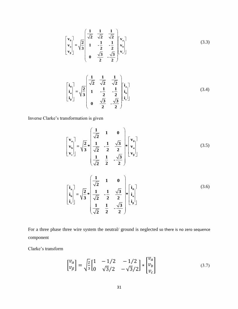
31
(3.3)
0 a
α b
β c
1 1 1
2 2 2i i2 1 1
i = 1 - - i3 2 2
i i3 3
0 -2 2
(3.4)
Inverse Clarke’s transformation is given
a 0
b α
c β
11 0
2v v
2 1 1 3v = * - * v
3 2 22v v
1 1 3-
2 22
(3.5)
(3.6)
For a three phase three wire system the neutral/ ground is neglected so there is no zero sequence
component
Clarke’s transform
0 a
α b
β c
1 1 1
2 2 2v v2 1 1
v = 1 - - v3 2 2
v v3 3
0 -2 2
a 0
b α
c β
11 0
2i i
2 1 1 3i = * - * i
3 2 22i i
1 1 3-
2 22
[𝑣𝛼
𝑣𝛽] = √
2
3[1 −1 2⁄ −1 2⁄
0 √3 2⁄ −√3 2⁄] ∗ [
𝑣𝑎
𝑣𝑏
𝑣𝑐
] (3.7)
32
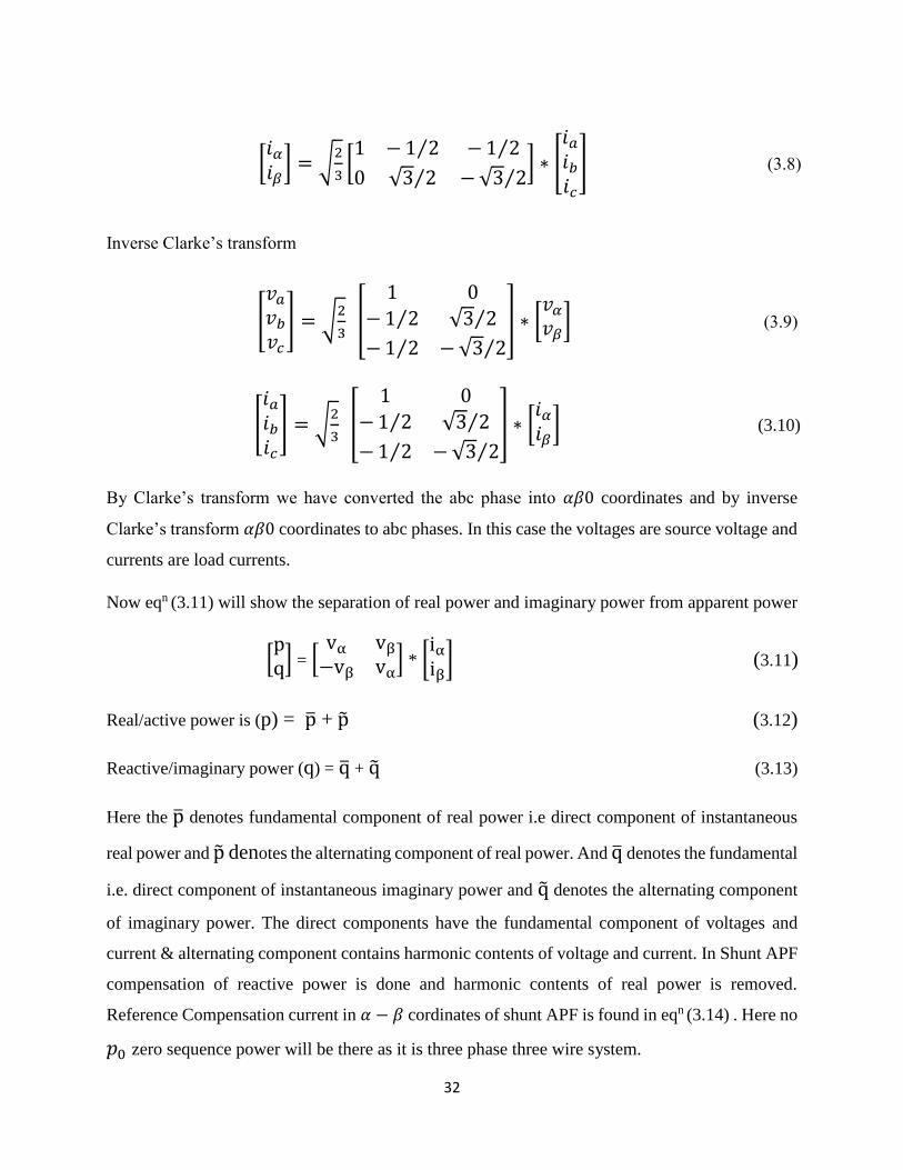
Inverse Clarke’s transform
By Clarke’s transform we have converted the abc phase into 𝛼𝛽0 coordinates and by inverse
Clarke’s transform 𝛼𝛽0 coordinates to abc phases. In this case the voltages are source voltage and
currents are load currents.
Now eqn (3.11) will show the separation of real power and imaginary power from apparent power
[pq] = [
vα vβ
−vβ vα] * [
iαiβ
] (3.11)
Real/active power is (p) = p̅ + p̃ (3.12)
Reactive/imaginary power (q) = q̅ + q̃ (3.13)
Here the p̅ denotes fundamental component of real power i.e direct component of instantaneous
real power and p̃ denotes the alternating component of real power. And q̅ denotes the fundamental
i.e. direct component of instantaneous imaginary power and q̃ denotes the alternating component
of imaginary power. The direct components have the fundamental component of voltages and
current & alternating component contains harmonic contents of voltage and current. In Shunt APF
compensation of reactive power is done and harmonic contents of real power is removed.
Reference Compensation current in 𝛼 − 𝛽 cordinates of shunt APF is found in eqn (3.14) . Here no
𝑝0 zero sequence power will be there as it is three phase three wire system.
[𝑖𝛼𝑖𝛽
] = √2
3[1 −1 2⁄ −1 2⁄
0 √3 2⁄ −√3 2⁄] ∗ [
𝑖𝑎𝑖𝑏𝑖𝑐
] (3.8)
[
𝑣𝑎
𝑣𝑏
𝑣𝑐
] = √2
3 [
1 0
−1 2⁄ √3 2⁄
−1 2⁄ −√3 2⁄
] ∗ [𝑣𝛼
𝑣𝛽] (3.9)
[
𝑖𝑎𝑖𝑏𝑖𝑐
] = √2
3 [
1 0
−1 2⁄ √3 2⁄
−1 2⁄ −√3 2⁄
] ∗ [𝑖𝛼𝑖𝛽
] (3.10)
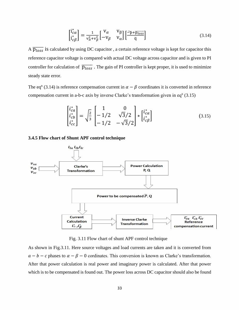
33
[i𝑐𝛼∗
i𝑐𝛽∗ ] =
1
v𝛼2+v𝛽
2 [v𝛼 vβ
−v𝛽 vα] [
−p̃+p𝑙𝑜𝑠𝑠̅̅ ̅̅ ̅̅ ̅
q̅] (3.14)
A p𝑙𝑜𝑠𝑠̅̅ ̅̅ ̅̅ is calculated by using DC capacitor , a certain reference voltage is kept for capacitor this
reference capacitor voltage is compared with actual DC voltage across capacitor and is given to PI
controller for calculation of p𝑙𝑜𝑠𝑠̅̅ ̅̅ ̅̅ . The gain of PI controller is kept proper, it is used to minimize
steady state error.
The eqn (3.14) is reference compensation current in 𝛼 − 𝛽 coordinates it is converted in reference
compensation current in a-b-c axis by inverse Clarke’s transformation given in eqn (3.15)
3.4.5 Flow chart of Shunt APF control technique
Fig. 3.11 Flow chart of shunt APF control technique
As shown in Fig.3.11. Here source voltages and load currents are taken and it is converted from
𝑎 − 𝑏 − 𝑐 phases to 𝛼 − 𝛽 − 0 cordinates. This conversion is known as Clarke’s transformation.
After that power calculation is real power and imaginary power is calculated. After that power
which is to be compensated is found out. The power loss across DC capacitor should also be found
[
𝑖𝑐𝑎∗
𝑖𝑐𝑏∗
𝑖𝑐𝑐∗
] = √2
3 [
1 0
−1 2⁄ √3 2⁄
−1 2⁄ −√3 2⁄
] ∗ [𝑖𝑐𝛼∗
𝑖𝑐𝛽∗ ] (3.15)
34
out. It is found with the help of PI controller. Gain of PI controller is kept proper. Power which is
to be compensated are harmonic component of real power and whole imaginary power. Then after
this current is calculated in 𝛼 − 𝛽 coordinates. This currents in 𝛼 − 𝛽 coordinates are transformed
into 𝑎 − 𝑏 − 𝑐 axis by inverse Clarke’s transformation. This is the reference compensating current.
It is given to hysteresis current controller along with shunt APF actual output current. In current
calculation low pass filter is used to remove higher order harmonics of power.
3.4.6 Hysteresis Current Controller
Hysteresis controller is used as it is simple, it has fast transient response, it enhances stability,&
has good accuracy. Hysteresis current controller is used for producing switching signal by
comparing the error present in the current in a fixed tolerance band. Here comparison is done
between the actual current & reference current within a fixed tolerance band. It is different for
different phases.
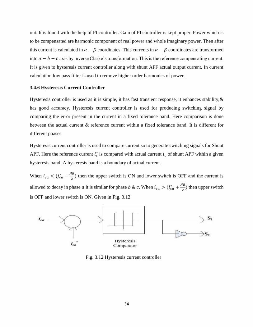
Hysteresis current controller is used to compare current so to generate switching signals for Shunt
APF. Here the reference current 𝑖𝑐∗ is compared with actual current 𝑖𝑐 of shunt APF within a given
hysteresis band. A hysteresis band is a boundary of actual current.
When 𝑖𝑐𝑎 < (𝑖𝑐𝑎∗ −
𝐻𝐵
2) then the upper switch is ON and lower switch is OFF and the current is
allowed to decay in phase 𝑎 it is similar for phase 𝑏 & 𝑐. When 𝑖𝑐𝑎 > (𝑖𝑐𝑎∗ +
𝐻𝐵
2) then upper switch
is OFF and lower switch is ON. Given in Fig. 3.12
Fig. 3.12 Hysteresis current controller
35
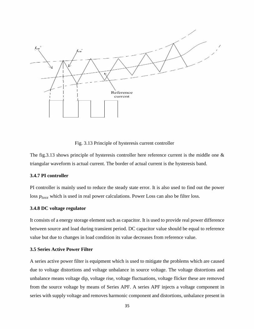
Fig. 3.13 Principle of hysteresis current controller
The fig.3.13 shows principle of hysteresis controller here reference current is the middle one &
triangular waveform is actual current. The border of actual current is the hysteresis band.
3.4.7 PI controller
PI controller is mainly used to reduce the steady state error. It is also used to find out the power
loss 𝑝𝑙𝑜𝑠𝑠 which is used in real power calculations. Power Loss can also be filter loss.
3.4.8 DC voltage regulator
It consists of a energy storage element such as capacitor. It is used to provide real power difference
between source and load during transient period. DC capacitor value should be equal to reference
value but due to changes in load condition its value decreases from reference value.
3.5 Series Active Power Filter
A series active power filter is equipment which is used to mitigate the problems which are caused
due to voltage distortions and voltage unbalance in source voltage. The voltage distortions and
unbalance means voltage dip, voltage rise, voltage fluctuations, voltage flicker these are removed
from the source voltage by means of Series APF. A series APF injects a voltage component in
series with supply voltage and removes harmonic component and distortions, unbalance present in

36
voltage waveform. The series APF is used to remove all these voltage problems from supply
voltage and make load voltage perfectly balanced and regulated. Series APF is connected in series
with transmission line with a series transformer. The turns ratio of series transformer should be
proper so that the injected voltage should come properly. Here three phase reference voltage is
calculated by transforming 𝑎 − 𝑏 − 𝑐 to 𝑑 − 𝑞 − 0 reference frame and again by transforming 𝑑 −
𝑞 − 0 to 𝑎 − 𝑏 − 𝑐 frame. After that the reference voltage is given to hysteresis voltage controller
with the actual output voltage of series APF (voltage we got across series transformer) and the
PWM signal is generated which is given to voltage source inverter. The DC voltage is given across
VSI so to get real power difference between source and load.
3.5.1 Block Diagram of Series APF
Fig. 3.14 Basic Control design of Series APF
As given in Fig.3.14, here is= source current
vinj= injected voltage across transformer
iL= load current
Vdc= dc voltage

37
3.5.2 Basic structure of series APF
The basic structure of series APF contains
(i) Series Transformer
(ii) DC Voltage regulator
(iii) Voltage source inverter
(iv) Hysteresis Voltage controller
3.5.3 Steps for controlling series APF
(i) Generation of reference compensating voltage
(ii) Comparing reference compensating voltage with actual compensating voltage in hysteresis
voltage controller and generating PWM signal for voltage source inverter.
3.5.4 Control scheme of series APF
The control pattern of series APF is based on Park’s transformation or 𝑑𝑞0 transformation. Here
we compared the reference voltage with actual output voltage of series APF. The supply voltage
is first converted into 𝑑𝑞0 coordinates form 𝑎𝑏𝑐 phases. Then this output voltage is compared with
input reference voltage which is first converted into 𝑑𝑞𝑜 coordinates. After comparing this two
voltages they are again transformed from 𝑑𝑞𝑜 coordinates to 𝑎𝑏𝑐 phases. The 𝑤𝑡 required in
converting 𝑑𝑞𝑜 to 𝑎𝑏𝑐 coordinates or vice versa we get from PLL (phase locked loop). After this
the supply voltage is given to PLL and 𝑤𝑡 is generated. Then this 𝑤𝑡 along with 𝑑𝑞𝑜 output
voltages are transformed into 𝑎𝑏𝑐 phases which is the reference output voltage. Then this reference
output voltage (vc*) is compared with sensed series APF output voltage (vc) in hysteresis voltage
controller and PWM signal is generated which is given to VSI. The PLL is a control system that
generates an output signal whose phase is related to phase of an input signal. For simplicity zero
sequence component is ignored.
The 𝑑𝑞𝑜 transformation to 𝑎𝑏𝑐 transformation are given below
[
𝑣𝑑
𝑣𝑞
𝑣0
] =2
3
[ sin (𝜔𝑡) sin (𝜔𝑡 −
2𝜋
3) sin (𝜔𝑡 +
2𝜋
3)
cos (𝜔𝑡) 𝑐𝑜𝑠(𝜔𝑡 −2𝜋
3) 𝑐𝑜𝑠(𝜔𝑡 +
2𝜋
3)
1
2
1
2
1
2 ]
[
𝑣𝑎
𝑣𝑏
𝑣𝑐
] (3.16)

38
Inverse Park’s transform i.e from 𝑎𝑏𝑐 to 𝑑𝑞𝑜 transform
[
𝑣𝑑
𝑣𝑞
𝑣0
] =
[
sin (𝜔𝑡) cos (𝜔𝑡) 1
sin (𝜔𝑡 −2𝜋
3) cos (𝜔𝑡 −
2𝜋
3) 1
sin (𝜔𝑡 +2𝜋
3) cos (𝜔𝑡 +
2𝜋
3) 1]
[
𝑣𝑎
𝑣𝑏
𝑣𝑐
] (3.17)
3.5.5 Flow chart of series APF control technique
Fig. 3.15 Flow chart of control technique of series APF
The Fig.3.15 shows the Flow chart of control technique of series APF
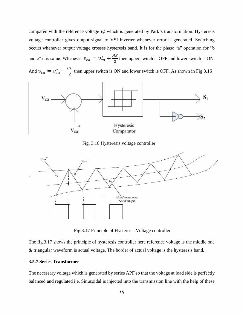
3.5.6 Hysteresis Voltage Controller
A hysteresis voltage controller is used to generate the PWM signal for VSI. In this the
instantaneous value of output voltage or sensed output series APF voltage (Injected voltage,𝑣𝑐) is
39
compared with the reference voltage 𝑣𝑐∗ which is generated by Park’s transformation. Hysteresis
voltage controller gives output signal to VSI inverter whenever error is generated. Switching
occurs whenever output voltage crosses hysteresis band. It is for the phase “a” operation for “b
and c” it is same. Whenever 𝑣𝑐𝑎 = 𝑣𝑐𝑎∗ +
𝐻𝐵
2 then upper switch is OFF and lower switch is ON.
And 𝑣𝑐𝑎 = 𝑣𝑐𝑎∗ −
𝐻𝐵
2 then upper switch is ON and lower switch is OFF. As shown in Fig.3.16
Fig. 3.16 Hysteresis voltage controller
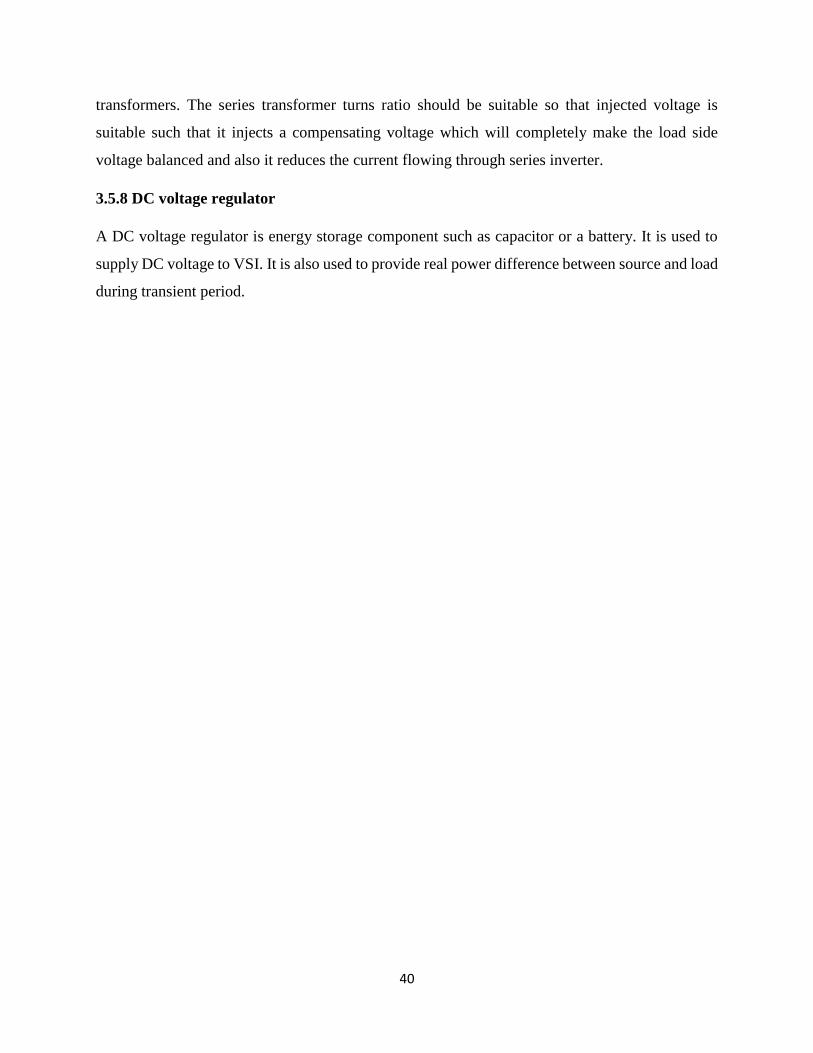
Fig.3.17 Principle of Hysteresis Voltage controller
The fig.3.17 shows the principle of hysteresis controller here reference voltage is the middle one
& triangular waveform is actual voltage. The border of actual voltage is the hysteresis band.
3.5.7 Series Transformer
The necessary voltage which is generated by series APF so that the voltage at load side is perfectly
balanced and regulated i.e. Sinusoidal is injected into the transmission line with the help of these
40
transformers. The series transformer turns ratio should be suitable so that injected voltage is
suitable such that it injects a compensating voltage which will completely make the load side
voltage balanced and also it reduces the current flowing through series inverter.
3.5.8 DC voltage regulator
A DC voltage regulator is energy storage component such as capacitor or a battery. It is used to
supply DC voltage to VSI. It is also used to provide real power difference between source and load
during transient period.
41
Chapter 4
RESULTS AND DISCUSSIONS
4.1 Introduction
4.2 Simulation Results of Shunt APF
4.3 Simulation Results of Series APF
4.4 Simulation Results of UPQC
42
4.1 Introduction
The simulation results are discussed in this chapter. In Shunt APF “p-q theory” and hysteresis
current controller was used for getting simulation results. In Series APF “dq0 transformation” and
hysteresis voltage controller were used for getting simulation results. After that Shunt APF and
Series APF were combined to get simulation results and Combination is known as UPQC.
4.2 Simulation Results of Shunt APF
Shunt APF is used to remove problems due to current harmonics. So it makes current drawn from
source completely sinusoidal which is effected by load current harmonics. In Table-4.1 system
parameters of shunt APF are given
Table-4.1 System Parameters used for Shunt APF
Supply Voltage 400 V
Line impedance Rs= 0.01 , Ls= 1 𝜇H
DC Voltage 850 V
DC capacitor 500 𝜇F
Load impedance RL=0.0001 , LL=1 𝜇H
Line frequency 50 Hz
Fig. 4.1 Load current of Shunt APF
43
In fig.4.1 the waveform of load current of shunt APF is given and they are not sinusoidal due to
presence of non-linear loads. This is non-linear waveform. They are Non-linear due to presence
non-linear loads like diode etc.
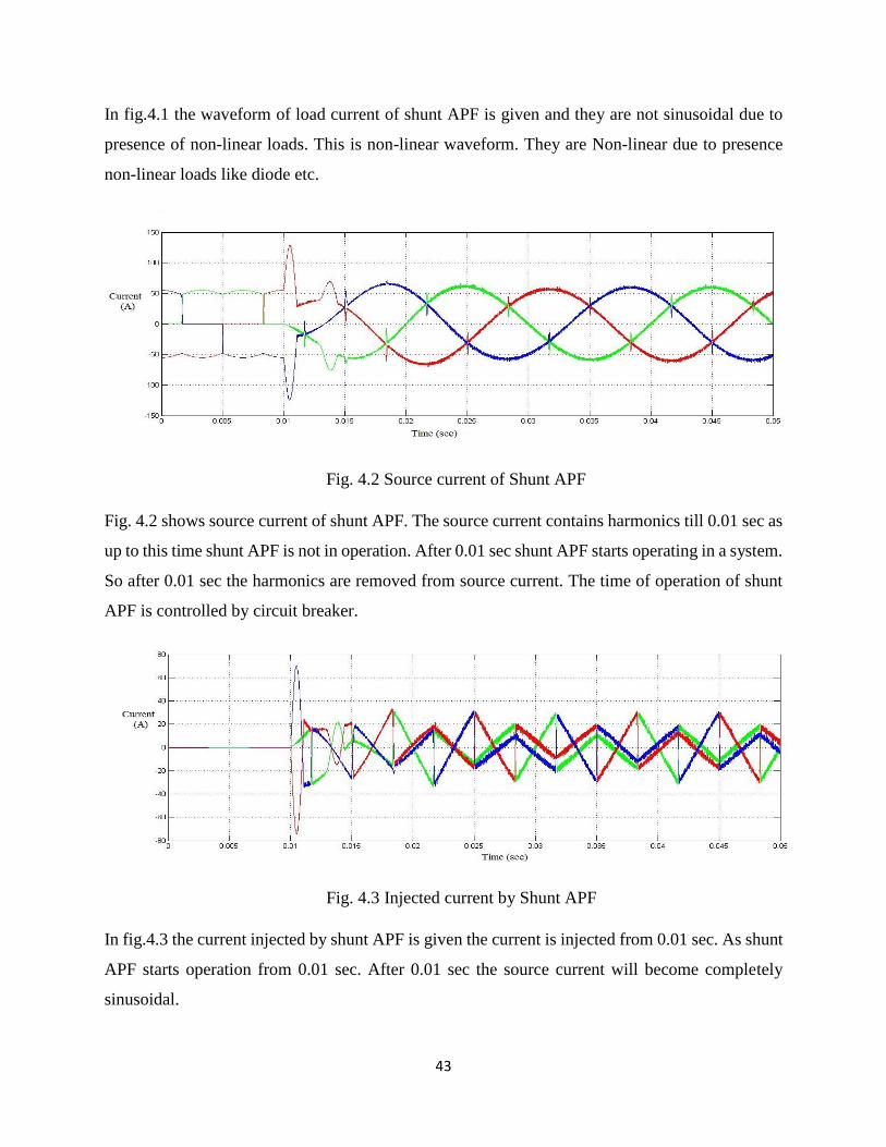
Fig. 4.2 Source current of Shunt APF
Fig. 4.2 shows source current of shunt APF. The source current contains harmonics till 0.01 sec as
up to this time shunt APF is not in operation. After 0.01 sec shunt APF starts operating in a system.
So after 0.01 sec the harmonics are removed from source current. The time of operation of shunt
APF is controlled by circuit breaker.
Fig. 4.3 Injected current by Shunt APF
In fig.4.3 the current injected by shunt APF is given the current is injected from 0.01 sec. As shunt
APF starts operation from 0.01 sec. After 0.01 sec the source current will become completely
sinusoidal.

44
Fig. 4.4 Capacitor Voltage
In Fig.4.4 capacitor voltage is given. After 0.01 sec capacitor voltage rises and become constant.
Because after that shunt APF starts operating. And DC capacitor always try to follow reference
DC voltage which is 850 V.
Fig. 4.5 THD of load current of shunt APF
In Fig.4.5 the THD of load current is shown. The THD in load current is 30.31% as the load
contains non-linear load.
45
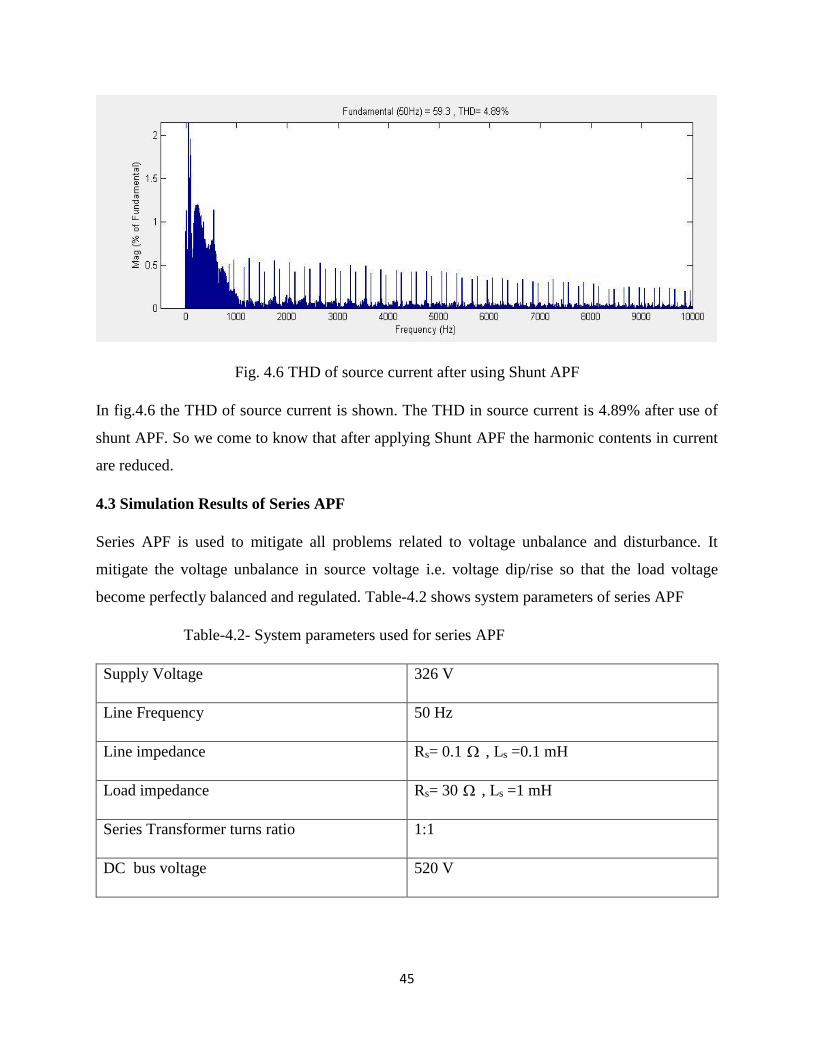
Fig. 4.6 THD of source current after using Shunt APF
In fig.4.6 the THD of source current is shown. The THD in source current is 4.89% after use of
shunt APF. So we come to know that after applying Shunt APF the harmonic contents in current
are reduced.
4.3 Simulation Results of Series APF
Series APF is used to mitigate all problems related to voltage unbalance and disturbance. It
mitigate the voltage unbalance in source voltage i.e. voltage dip/rise so that the load voltage
become perfectly balanced and regulated. Table-4.2 shows system parameters of series APF
Table-4.2- System parameters used for series APF
Supply Voltage 326 V
Line Frequency 50 Hz
Line impedance Rs= 0.1 , Ls =0.1 mH
Load impedance Rs= 30 , Ls =1 mH
Series Transformer turns ratio 1:1
DC bus voltage 520 V
46
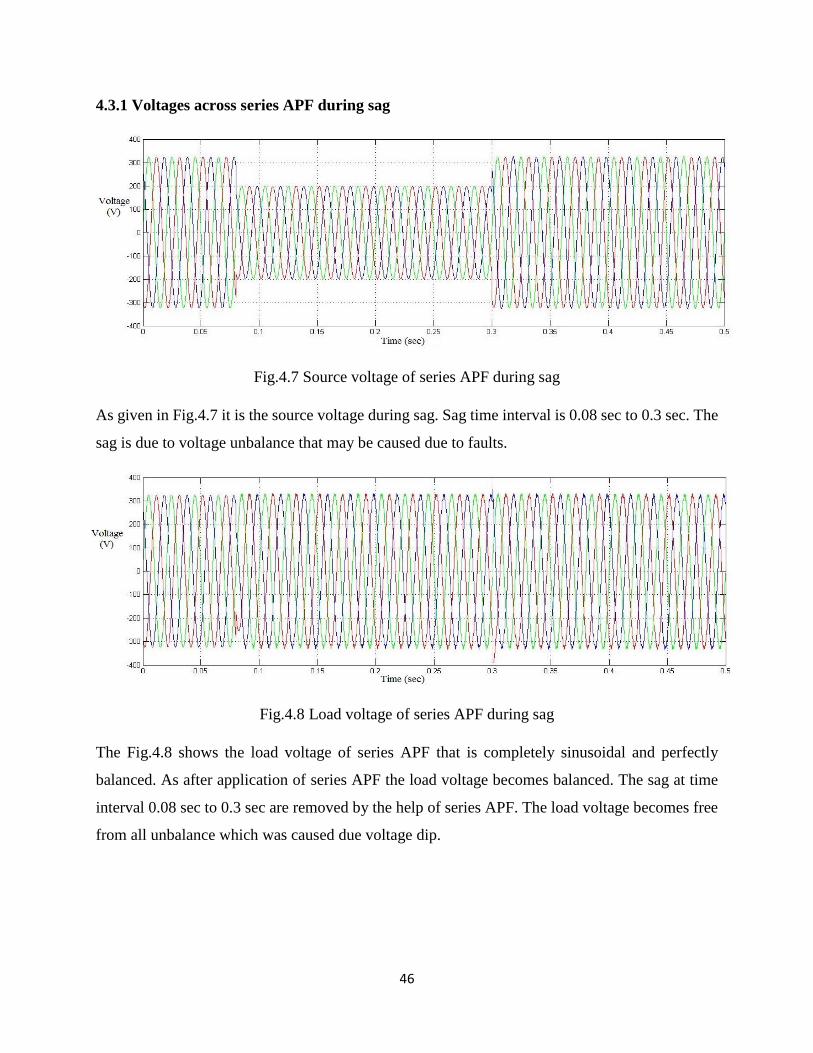
4.3.1 Voltages across series APF during sag
Fig.4.7 Source voltage of series APF during sag
As given in Fig.4.7 it is the source voltage during sag. Sag time interval is 0.08 sec to 0.3 sec. The
sag is due to voltage unbalance that may be caused due to faults.
Fig.4.8 Load voltage of series APF during sag
The Fig.4.8 shows the load voltage of series APF that is completely sinusoidal and perfectly
balanced. As after application of series APF the load voltage becomes balanced. The sag at time
interval 0.08 sec to 0.3 sec are removed by the help of series APF. The load voltage becomes free
from all unbalance which was caused due voltage dip.

47
Fig. 4.9 Voltage injected by series APF
In Fig.4.9 the voltage injected by series APF is shown. The injected voltage time interval is 0.08
sec to 0.3 sec. By injecting voltage in this time interval the load side voltage is made completely
balanced and sinusoidal.
4.3.2 Voltage across series APF during swell
Fig. 4.10 Source voltage during swell of series APF
This fig.4.10 indicates the source voltage of series APF during swell condition. Here the swell is
from 0.08 sec to 0.3 sec. There is rise in magnitude of voltage form time interval 0.08 to 0.3 sec.
The voltage swell may be due to faults or capacitor switching.

48
Fig. 4.11 Load Voltage during swell of series APF
In Fig.4.11 the load voltage of series APF during swell is given. Due to operation of series APF
the voltage swell from time interval 0.08 sec to 0.3 sec are removed and the load voltage becomes
completely balanced. Now the voltage is completely balanced in whole interval of time.
Fig. 4.12 Injected voltage during swell of series APF
Fig.4.12 shows the injected voltage by series APF during swell condition. The voltage is injected
in time interval 0.08 sec to 0.3 sec. By injecting this voltage the load voltage across series APF
becomes completely regulated.
4.4 Simulation results of UPQC
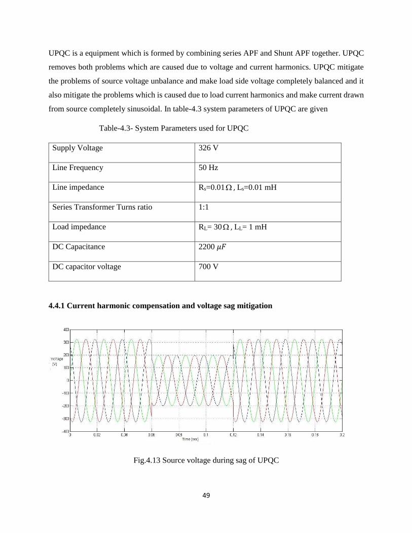
49
UPQC is a equipment which is formed by combining series APF and Shunt APF together. UPQC
removes both problems which are caused due to voltage and current harmonics. UPQC mitigate
the problems of source voltage unbalance and make load side voltage completely balanced and it
also mitigate the problems which is caused due to load current harmonics and make current drawn
from source completely sinusoidal. In table-4.3 system parameters of UPQC are given
Table-4.3- System Parameters used for UPQC
Supply Voltage 326 V
Line Frequency 50 Hz
Line impedance Rs=0.01 , Ls=0.01 mH
Series Transformer Turns ratio 1:1
Load impedance RL= 30 , LL= 1 mH
DC Capacitance 2200 𝜇𝐹
DC capacitor voltage 700 V
4.4.1 Current harmonic compensation and voltage sag mitigation
Fig.4.13 Source voltage during sag of UPQC

50
In fig.4.13 source voltage of UPQC during sag is shown. Total simulation time is 0.2 sec. The
voltage dip is from 0.06 sec to 0.12 sec. It is due to presence of faults in the system. Due to sag the
voltage from 0.06 sec to 0.12 sec is 200 V.
Fig. 4.14 Load voltage during sag after application of UPQC
In Fig.4.14 load voltage of UPQC is shown. After operation of UPQC the sag from time 0.06 sec
to 0.12 sec is removed. UPQC removes the voltage sag problems. The total load voltage becomes
sinusoidal and gains its original magnitude which is 326 V.
Fig. 4.15 Injected Voltage of UPQC during sag
Fig.4.15 shows the injected voltage of UPQC during sag. The voltage is injected form 0.06 sec to
0.12 sec so that the load voltage becomes completely balanced.

51
Fig. 4.16 Load current of UPQC during sag
In Fig.4.16 load current of UPQC during sag is shown. The load current of UPQC is contains
harmonics and is non-linear due to presence of non-linear load.
Fig. 4.17 Source current during sag after operation of UPQC
Fig. 4.17 shows source current during sag after application of UPQC. The source current of UPQC
is sinusoidal and harmonics are removed after 0.06 sec as after that UPQC starts operating. For
current compensation the shunt APF part of UPQC operates.
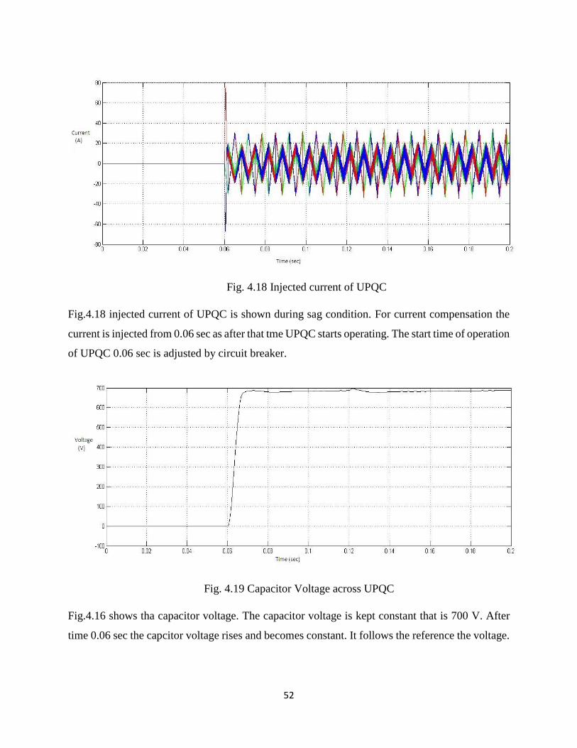
52
Fig. 4.18 Injected current of UPQC
Fig.4.18 injected current of UPQC is shown during sag condition. For current compensation the
current is injected from 0.06 sec as after that tme UPQC starts operating. The start time of operation
of UPQC 0.06 sec is adjusted by circuit breaker.
Fig. 4.19 Capacitor Voltage across UPQC
Fig.4.16 shows tha capacitor voltage. The capacitor voltage is kept constant that is 700 V. After
time 0.06 sec the capcitor voltage rises and becomes constant. It follows the reference the voltage.
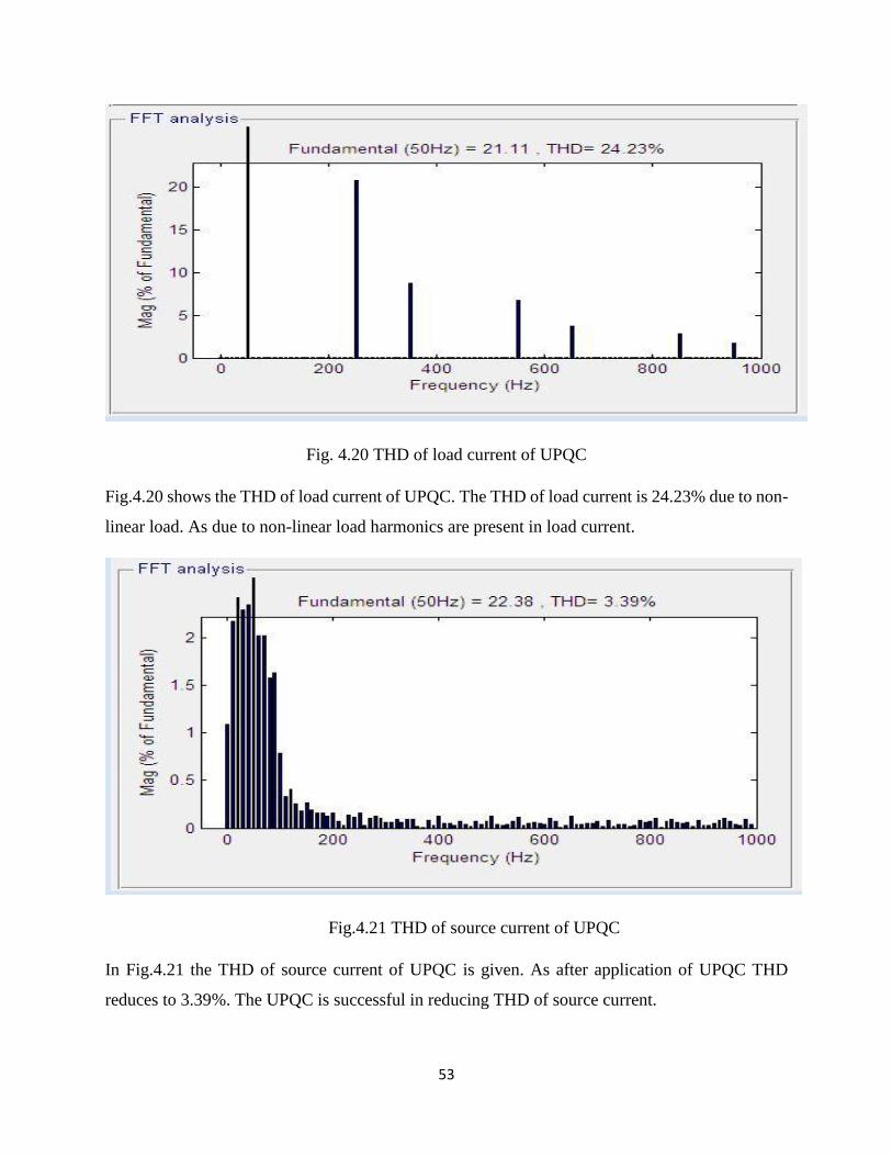
53
Fig. 4.20 THD of load current of UPQC
Fig.4.20 shows the THD of load current of UPQC. The THD of load current is 24.23% due to non-
linear load. As due to non-linear load harmonics are present in load current.
Fig.4.21 THD of source current of UPQC
In Fig.4.21 the THD of source current of UPQC is given. As after application of UPQC THD
reduces to 3.39%. The UPQC is successful in reducing THD of source current.
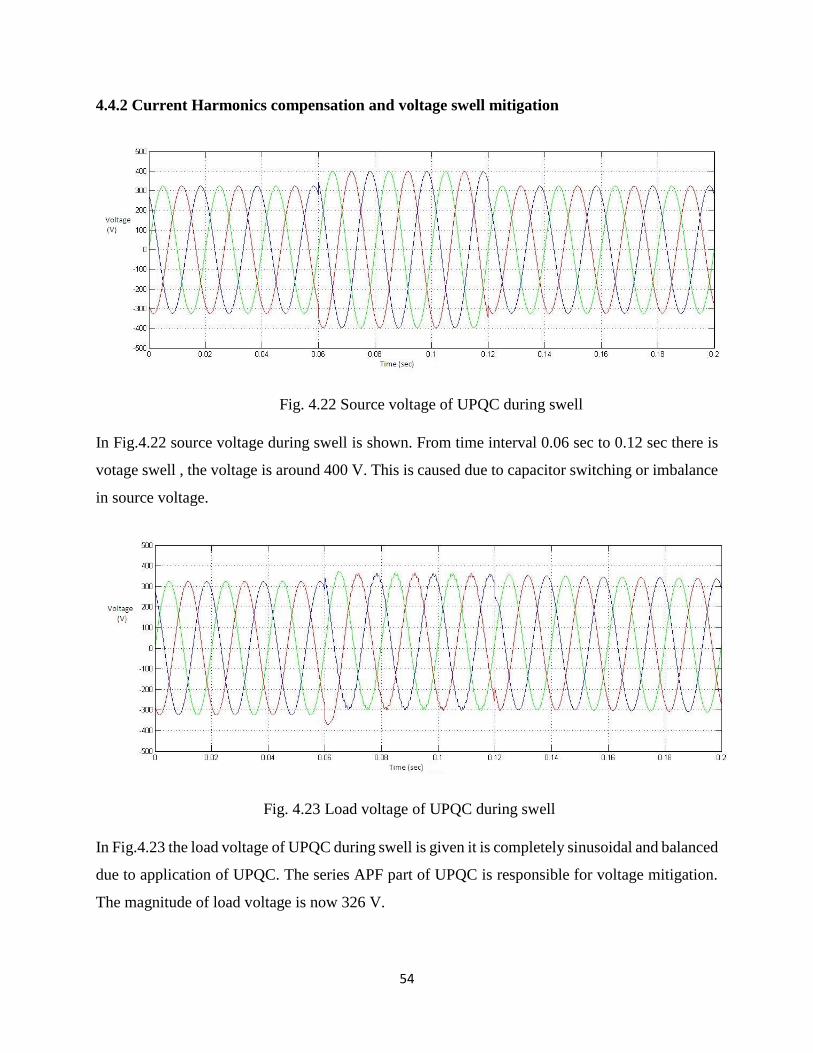
54
4.4.2 Current Harmonics compensation and voltage swell mitigation
Fig. 4.22 Source voltage of UPQC during swell
In Fig.4.22 source voltage during swell is shown. From time interval 0.06 sec to 0.12 sec there is
votage swell , the voltage is around 400 V. This is caused due to capacitor switching or imbalance
in source voltage.
Fig. 4.23 Load voltage of UPQC during swell
In Fig.4.23 the load voltage of UPQC during swell is given it is completely sinusoidal and balanced
due to application of UPQC. The series APF part of UPQC is responsible for voltage mitigation.
The magnitude of load voltage is now 326 V.
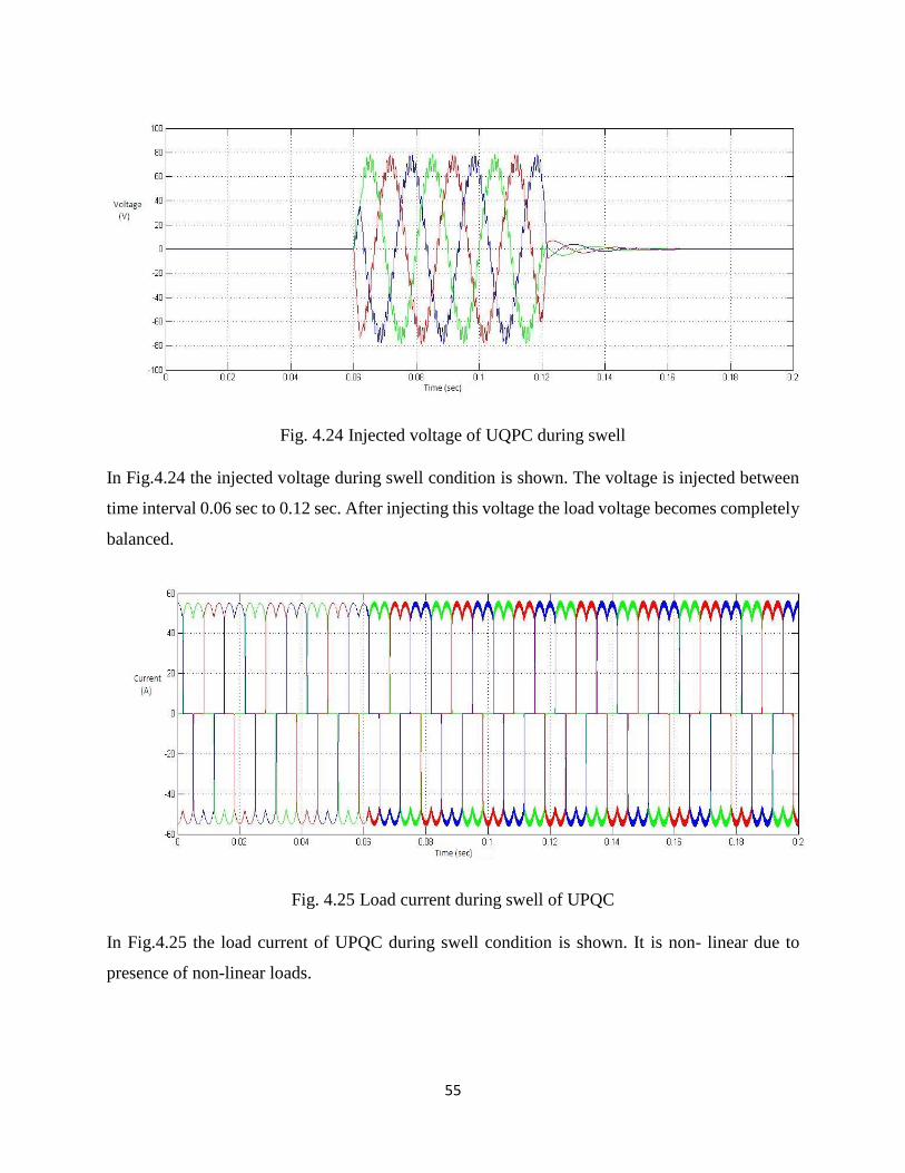
55
Fig. 4.24 Injected voltage of UQPC during swell
In Fig.4.24 the injected voltage during swell condition is shown. The voltage is injected between
time interval 0.06 sec to 0.12 sec. After injecting this voltage the load voltage becomes completely
balanced.
Fig. 4.25 Load current during swell of UPQC
In Fig.4.25 the load current of UPQC during swell condition is shown. It is non- linear due to
presence of non-linear loads.

56
Fig. 4.26 Source current of UPQC during swell
In Fig.4.26 the source current of UPQC during swell condition is shown. The source current is
sinusoidal after 0.06 sec as after that the UPQC operates. The source current is sinusoidal mainly
due to operation of shunt APF part of UPQC. The operating time of Shunt APF part is controlled
by circuit breaker.
Fig. 4.27 Injected current of UPQC during swell
The Fig.4.27 shows injected current of UPQC during swell condition. Current is injected from
time 0.06 sec to compenate for load current non-linearity and make source current completely
sinusoidal.
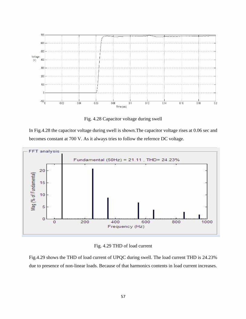
57
Fig. 4.28 Capacitor voltage during swell
In Fig.4.28 the capacitor voltage during swell is shown.The capacitor voltage rises at 0.06 sec and
becomes constant at 700 V. As it always tries to follow the refernce DC voltage.
Fig. 4.29 THD of load current
Fig.4.29 shows the THD of load current of UPQC during swell. The load current THD is 24.23%
due to presence of non-linear loads. Because of that harmonics contents in load current increases.

58
Fig.4.30 THD of source current
Fig.4.30 shows the THD of source current during swell. After use of UPQC the THD of source
current reduces 3.39%. As UPQC eliminates all kind of problems due to current harmonics.

59
Chapter 5
CONCLUSIONS AND FUTURE SCOPE
5.1 Conclusions
5.2 Future Scope

60
5.1 Concluisons
Unified quality conditioner was studied and investigated in this thesis for power quality
enrichement. UPQC is a type of advance hybrid filter which uses series APF for removal of voltage
realted problmes like voltage dip/rise, fluctutaion, imbalance and shunt APF for removal of
harmonics in current harmonics.What type of problems are there in power quality was studied and
discussed. UPQC system is developed and discussed in detail.
The simulink models of Shunt APF , Series APF, UPQC are developed.
Shunt APF model is developed using “p-q Theory” and control techniques used here is
hystersis current controller. The simulation is done and current harmonics are eliminated
and current drawn from source is completely sinusoidal. The THD of source current is
within the limit that is 5%.
Series APF model is developed using Park’s transformation and controlling techniques
used are hystersis voltage controller. The simulation is done and source voltage dip/rise are
mitigated and load voltage is made comletely balanced.
UPQC model was developed by joining Shunt APF and series APF back to back using DC
capacitor. The controlling techniques used here are hystersis band controller. The
simuation is done and current harmonics are removed and source current is complerely
sinusoidal. And the voltage dip/rise in supply side is mitigated and load voltage is perfectly
balanced. The THD of source current is within the limit that is lees than 5%.
5.2 Future Scope
The UPQC model can be enhanced and enriched to terminate the power quality problems in a
power system. The various ways for doing that:-
The prototype of this UPQC model can be esatablished in laboratory.
UPQC model can be established for three phase four wire system for the non-linear load
and unstable voltage.
Here the UPQC model developed was right shunt UPQC, further we can develop model
for left shunt UPQC.
We can connect wind turbines, solar energy system that is renewable source of energy to
UPQC to get improved power in consumer ends during serious conditions.
61
REFERENCES
[1] H. Akagi, “Trends in active line conditioner”, IEEE Transactions On Power Electronics,
vol.9, no.3, 1994.
[2] H. Fujita and H. Akagi, “ The Unified Power Quality Conditioner : The integration of series
and shunt active filters” IEEE Transactions on Power Electronics, vol.13, no.2 March 1998.
[3] N. Hingorani, “Introducing Custom Power,” IEEE Spectrum, Vol.32, Issue: 6, June
1995,pp 41-48.
[4] H. Awad, M. H.J Bollen, “Power Electronics for Power Quality Improvements,” IEEE
Symposium on Industrial Electronics, 2003, vol.2, pp. 1129-1136
[5] Bhim Singh, Kamal Al-Haddad and Ambrish Chandra , “A Review of Active Filters for
Power Quality Improvement” IEEE Trans. on Industrial Electronics, Vol.46, No.5, oct. 1999,
pp.960-971..
(6] H. Akagi, Y. Kanazawa, A. Nabae , “Generalized Theory of the Instantaneous Reactive
Power in Three Phase Circuits”, in Proeedings. IPEC-Tokyo’83 International Conf. Power
Electronics, Tokyo,.pp.1375-1386.
[7] H. Akagi, Y. Kanazawa, and A. Nabae, “Instantaneous reactive power compensators
comprising switching devices without energy storage components,” IEEE Transactions
Industry Applications, vol. IA-20, pp. 625-30, May/June 1984.
[8] E. H. Watanabe, R. M. Stephen, and M. Arcdes, “New concept of instantaneous active and
reactive powers in electric systems with generic load,” IEEE Transactions. on Power Delivery,
vol.8, April 1993, pp 697-703.
[9] Rosli Omar, Nasrudin Abd Rahim, Marizan sulaiman “Modeling and Simulation for
voltage sags/swells mitigation using dynamic voltage restorer (DVR)” IEEE journal on Power
Electronics Drives and Energy System.
[10] M. A. Chaudhari and Chandraprakash, “Three-Phase Series Active Power Filter as Power
Quality Conditioner,” IEEE International Conference on Power Electronics, Drives and
Energy Systems, Dec. 2012, pp 1-6.
62
[11] A. Banerji, S. K. Biswas, B. Singh, “DSTATCOM Control Algorithms: A Review,”
International Journal of Power Electronics and Drive System (IJPEDS), Vol.2, No.3,
September 2012, pp 285-296.
[12] Mehmet Ucar and Engin Ozdemir, “Control of a 3-phase 4-leg active power filter under
non-ideal mains voltage condition,” Electric Power Systems Research 78 (2008) 58–73.
[13] Srinivas Bhaskar Karanki, Mahesh K. Mishra,B. Kalyan Kumar,"Particle Swarm
Optimization Based Feedback Controller for Unified Power-Quality Conditioner", "IEEE
Transactions on Power Delivery, vol. 25, no. 4, October 2010".
[14] Vasudhra Mahajan, Pramod Agarwal, Hri Om Gupta “Simulation of shunt active power
filter using Instantaneous Power Theory” IEEE conference on Applied Power Electronics.
[15] Matin Kesler, Angin Ozadmir, “Synchronous Reference Frame based Control method of
UPQC under balanced and distorted load conditions”, IEEE Transactions on Industrial
Electronics, vol.58, no.9, sep 2011.
[16] Bhim Singh, Kamal Al-Haddad and Ambrish Chandra , “A Review of Active Filters for
Power Quality Improvement” IEEE Transactions on Industrial Electronics, Vol.46, No.5, oct
1999, pp 960-971.
[17] Fang Zheng Peng,and Jih-Sheng, “Generalized Instantaneous Reactive Power Theory for
Three phase Power Systems”IEEE Transactions on Instrumentation and Measurement, vol.
45, no. 1, February 1996.
[18] Yash Pal, A. Swarup, Bhim Singh, “A control strategy based on UTT and Ic of three-
phase, fourwire UPQC for power quality improvement ” International Journal of Engineering,
Science and Technology Vol. 3, No. 1, 2011, pp. 30-40.
[19] Metin Kesler and Engin Ozdemir, “A Novel Control Method for Unified Power Quality
Conditioner(UPQC ) Under Non-Ideal Mains Voltage and Unbalanced Load Conditions,”
IEEE Conference on Applied Power Electronics, Feb. 2010, pp. 374-379.
[20] Sai Shankar, Ashwani kumar and W.Gao “Operation of Unified Power Quality
Conditioner under Different Situation,” IEEE Proceedings Power and Energy Society General
Meeting, July 2011, 21, pp. 1-10.

63
[21] Chellali Benachaiba, Brahim Ferdi ,“Voltage Quality Improvement Using DVR,”
Electrical Power Quality and Utilisation, Journal Vol. XIV, No. 1, 2008.
[22] F. A. Jowder, “Modeling and Simulation of Dynamic Voltage Restorer (DVR) Based on
Hysteresis Voltage Control,” The 33rd Annual Conference of the IEEE Industrial Electronics
Society (IECON) Nov. 2007.
[23] F.A.L. Jowder , “Design and Analysis of dynamic voltage restorer for deep voltage sag
and harmonic compensation” ,IET Generation, Transmission & Distribution,2009,Vol.3,Iss.
6, pp. 547-560.
[24] V.Khadkikar, A.Chandra, A.O. Barry and T.D.Nguyen, “Conceptual Study of Unified
Power Quality Conditioner (UPQC),” IEEE International Symposium on Industrial
Electronics,vol.2, July 2006.


![Power Quality Improvement using Voltage Source Converter ... · power quality offered by the harmonic sensitive loads [5]. 2. THE UNIFIED POWER QUALITY CONDITIONER nified Power Quality](https://static.documents.pub/doc/80x56/5ed3578b4e15b65b4670b614/power-quality-improvement-using-voltage-source-converter-power-quality-offered.jpg)


