35
Copyright © 2013 Verilab & SNUG Sub-cycle Functional Timing Verification using SystemVerilog Assertions Anders Nordstrom [email protected] Verilab Inc.
| Date post: | 24-Mar-2018 |
| Category: |
Documents |
| Upload: | nguyenkhanh |
| View: | 221 times |
| Download: | 5 times |

Copyright © 2013 Verilab & SNUG
Sub-cycle Functional Timing Verification using SystemVerilog
Assertions
Anders Nordstrom [email protected]
Verilab Inc.

2 of 35
Anders Nordstrom
Copyright © 2013 Verilab & SNUG
Agenda
• System Under Verification • Verification Problem • Verification Approaches • Assertions in OVM • Assertions for Functional Timing Verification • Examples • Conclusions
Recommendations: Shown throughout the presentation

3 of 35
Anders Nordstrom
Copyright © 2013 Verilab & SNUG
System Under Verification
• Standard Dual In-line Memory Module (DIMM) – Equal track lengths for data – Address to every chip
DQ0
DQ31
DQ63

4 of 35
Anders Nordstrom
Copyright © 2013 Verilab & SNUG
System Under Verification
• Register PLL Dual In-line Memory Module (RDIMM) – Different track lengths for data – DUT is RPLL like device
DQ0
DQ63 DQ31
c ≈ 300,000km/s c ≈ 3cm/100ps

5 of 35
Anders Nordstrom
Copyright © 2013 Verilab & SNUG
DUT
tPDM tSTAOFF
6 of 35
Anders Nordstrom
Copyright © 2013 Verilab & SNUG
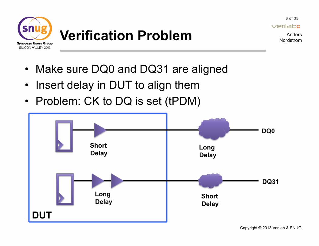
Verification Problem
• Make sure DQ0 and DQ31 are aligned • Insert delay in DUT to align them • Problem: CK to DQ is set (tPDM)
Long Delay
Long Delay
Short Delay
Short Delay
DQ0
DQ31
DUT

7 of 35
Anders Nordstrom
Copyright © 2013 Verilab & SNUG
Verification Problem cont.
• Must take PVT variations into account • DLL adds fixed delay • Compensates for delay variations
Long Delay
Short Delay
DQ0
DQ31
DUT
DLL
DLL

8 of 35
Anders Nordstrom
Copyright © 2013 Verilab & SNUG
Verification Approaches
• Problem: Vary PVT delay – Ensure programmed tPDM is maintained
• Extend OVM Environment – Already generating DDR3 transactions – Time stamps on transactions – Transaction timing, not signal timing
• Verilog Timing Checks • SystemVerilog Assertions

9 of 35
Anders Nordstrom
Copyright © 2013 Verilab & SNUG
Verification Approaches cont.
• Verilog Timing Checks – $setup(), $hold(), $width() – Inside specify block – Variable is
specparam – Error message
not customizable ✔
signal_width_check c_glitch (phy_clk); module signal_width_check (input wire signal2check); specify specparam min_width = 1250; $width(posedge signal2check, min_width); $width(negedge signal2check, min_width); endspecify endmodule // signal_width_check
Warning! Timing violation $width( negedge signal2check:73511332340 FS, : 73512580250 FS, 1260 : 1260 PS ); File: /home/andersn/phy_assert.sv, line = 576 Scope: harness.top.core.ddr_phy.phy_assert.c_glitch Time: 73512580250 FS

10 of 35
Anders Nordstrom
Copyright © 2013 Verilab & SNUG
Verification Approaches cont.
• SystemVerilog Assertions – Most flexible solution – Custom error messages – Easy to disable checking – Familiar to the team
✔
11 of 35
Anders Nordstrom
Copyright © 2013 Verilab & SNUG
Adding Assertions to an OVM Environment
• Where should assertions be located? • How do you access signals in other modules? • How do you exclude some or all assertions? • How do you use configuration data?

12 of 35
Anders Nordstrom
Copyright © 2013 Verilab & SNUG
Location of Assertions
• Assertions verify: – DUT I/O Relationships – Internal Signal Behaviors
• Inside DUT or Verification Environment? • Protocol assertions often in respective Interface • Interfaces can bind to interfaces or modules
Recommendation 1: Put assertions inside interfaces in separate files

13 of 35
Anders Nordstrom
Copyright © 2013 Verilab & SNUG
Cross Module References
• Accessing signals outside module bound to • Hierarchical connection in bind
• Direct Hierarchical name access
bind ddr_phy ddr_assert my_assert (.c_hclk (ckgen_inst.c_hclk), .*); interface ddr_assert (input c_hclk,
input rst_n);
`define OFFSET_REG harness.card_inst.dut_inst.inst_core.inst_phy.reg_inst interface ddr_assert (input c_hclk, input [1:0] rc10, input [7:0] ckq_off, ckdb_off); always @(*) case (rc10[1:0]) 2'b00: begin //DDR800 ckq_off = `OFFSET_REG.c_reg_ckq_off; ckdb_off = `OFFSET_REG.c_phy_ckdb_off;
Recommendation 2: Connect all signals explicitly in bind statement, if not connected by .*

14 of 35
Anders Nordstrom
Copyright © 2013 Verilab & SNUG
Excluding Assertions
• “-assert disable” compile option
– is not executed
• `ifdef around bind
assert($cast(this.my_parent, get_parent() ))
OVM_ERROR @ 0.000 ns: reporter [SVA phy_dll_assert] sdll phy_dll_assert sigo high or low period too short. Got 0 Expected x
Recommendation 3: Use assertions to check DUT signals only
Recommendation 4: Use `ifdef around bind and interface
15 of 35
Anders Nordstrom
Copyright © 2013 Verilab & SNUG
Excluding Assertions
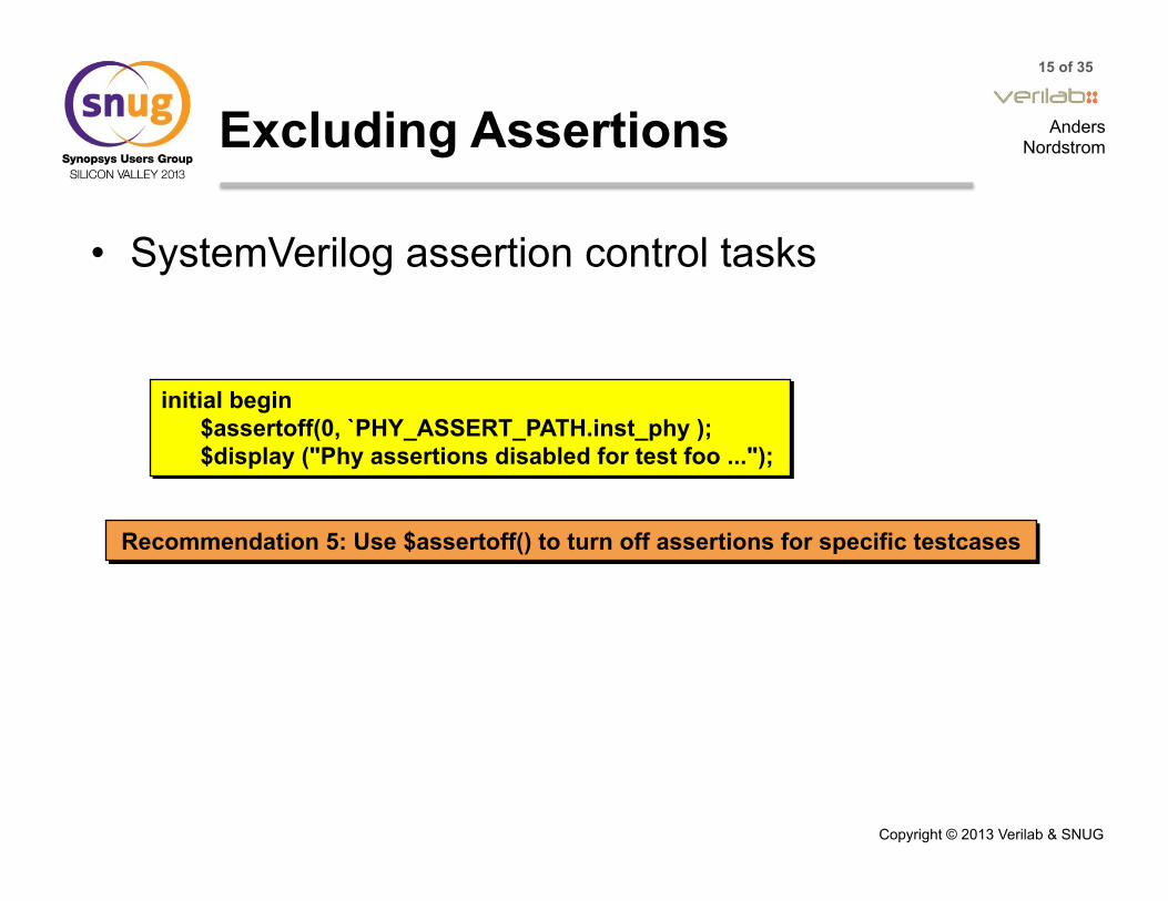
• SystemVerilog assertion control tasks
initial begin $assertoff(0, `PHY_ASSERT_PATH.inst_phy ); $display ("Phy assertions disabled for test foo ...");
Recommendation 5: Use $assertoff() to turn off assertions for specific testcases

16 of 35
Anders Nordstrom
Copyright © 2013 Verilab & SNUG
Configuration Information
• DDR3 Interface: 4 speeds, 2 voltages • Test environment write RC10 register at startup • Option1: Use register values in assertions
• Assertion check and DUT in sync • If DUT programming fails – assertion may not fail
bind phy ddr_assert my_assert(.rc10(reg_inst.rc10), .*); interface ddr_assert(input [1:0] rc10); time sim_period; always @(*) case(rc10[1:0]) 2'b00: sim_period = 2500ps; //DDR3-800
17 of 35
Anders Nordstrom
Copyright © 2013 Verilab & SNUG
Configuration Information cont.
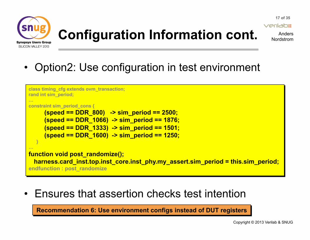
• Option2: Use configuration in test environment
• Ensures that assertion checks test intention Recommendation 6: Use environment configs instead of DUT registers
class timing_cfg extends ovm_transaction; rand int sim_period; … constraint sim_period_cons { (speed == DDR_800) -> sim_period == 2500; (speed == DDR_1066) -> sim_period == 1876; (speed == DDR_1333) -> sim_period == 1501; (speed == DDR_1600) -> sim_period == 1250; } … function void post_randomize(); harness.card_inst.top.inst_core.inst_phy.my_assert.sim_period = this.sim_period; endfunction : post_randomize

18 of 35
Anders Nordstrom
Copyright © 2013 Verilab & SNUG
Assertions for Functional Timing Verification
• Why is this a problem?
a_example: assert property (@(posedge clk) !(GntA && !ReqA))
clk
ReqA
GntA
No Reference Clock
Sampled in preponed
region
Jitter on signals
Un-even Simulator Support

19 of 35
Anders Nordstrom
Copyright © 2013 Verilab & SNUG
Sampling Point
• Requirement: “mux inputs to DLL are low immediately following mux select change”
• Immediate assertion:
mux_sel
sigo_0
sigo_1
a_mux_sel: assert property (@(mux_sel) (sigo_0==0 && sigo_1==0));
always @(mux_sel) a_mux_sel: assert (sigo_0==0 && sigo_1==0); ✔
✖

20 of 35
Anders Nordstrom
Copyright © 2013 Verilab & SNUG
Signal Jitter Impact
• Requirement: A high pulse on DQSEN must be 3 clock cycles long
• Assertion has clock, but jitter on DQSEN leads to: – false pass – false failures
clk
DQSEN
a_dqsen_length: assert property (@(posedge clk) $rose(DQSEN) |=> DQSEN[*2]);
1 2 3 0
21 of 35
Anders Nordstrom
Copyright © 2013 Verilab & SNUG
Signal Jitter Impact cont.
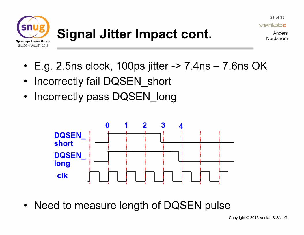
• E.g. 2.5ns clock, 100ps jitter -> 7.4ns – 7.6ns OK • Incorrectly fail DQSEN_short • Incorrectly pass DQSEN_long
• Need to measure length of DQSEN pulse
clk
DQSEN_ short
1 2 3 0 4
DQSEN_ long
22 of 35
Anders Nordstrom
Copyright © 2013 Verilab & SNUG
Signal Jitter Impact cont.
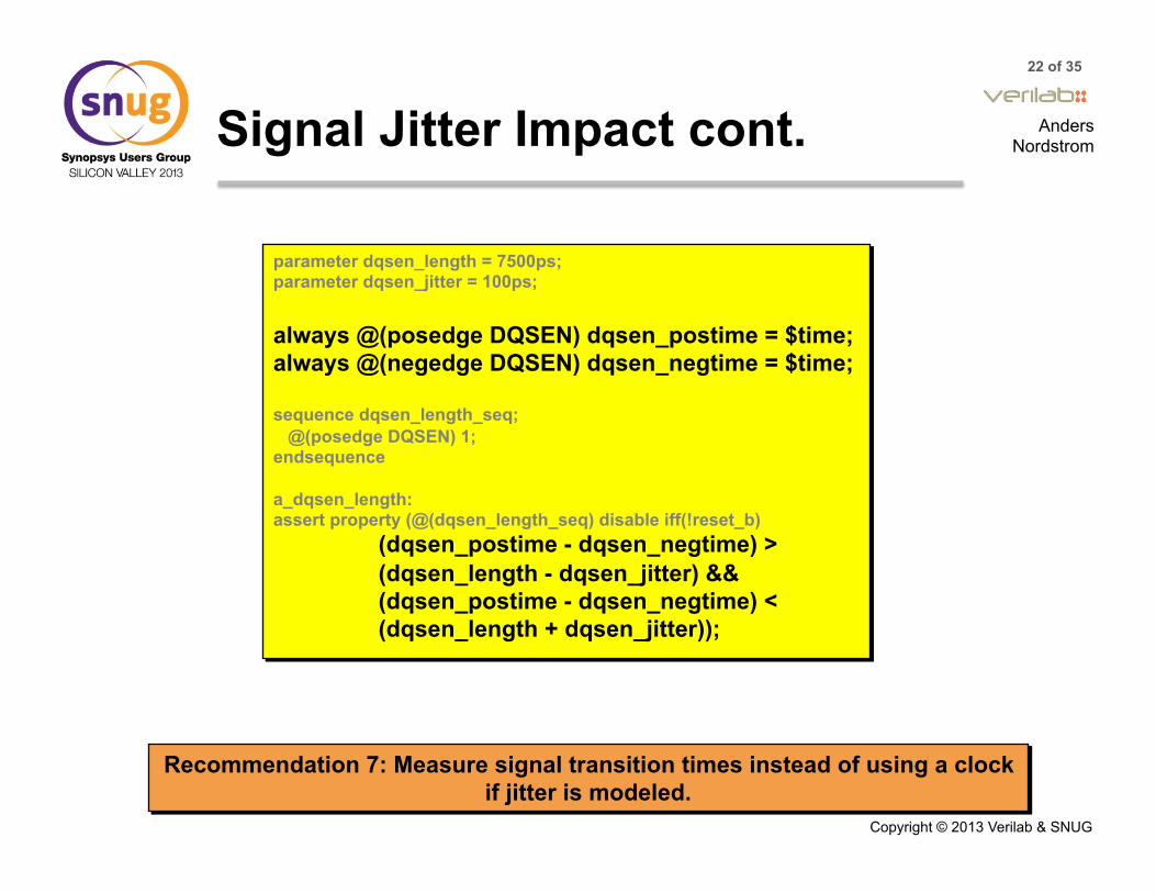
parameter dqsen_length = 7500ps; parameter dqsen_jitter = 100ps; always @(posedge DQSEN) dqsen_postime = $time; always @(negedge DQSEN) dqsen_negtime = $time; sequence dqsen_length_seq; @(posedge DQSEN) 1; endsequence a_dqsen_length: assert property (@(dqsen_length_seq) disable iff(!reset_b)
(dqsen_postime - dqsen_negtime) > (dqsen_length - dqsen_jitter) && (dqsen_postime - dqsen_negtime) < (dqsen_length + dqsen_jitter));
Recommendation 7: Measure signal transition times instead of using a clock if jitter is modeled.

23 of 35
Anders Nordstrom
Copyright © 2013 Verilab & SNUG
Incorrect Error Messages
• Requirement: Time for CLK to ODT change < ck2db_max
• Example of assertion error message:
always @ (posedge CLK) db_start_time = $time; always @ (ODT) ODT_delay = $time - db_start_time; a_ODT_delay_max: assert property (@(ODT_delay) ODT_delay <= ck2db_max) else ovm_report_error("ddr_assert", $psprintf(”ODT_delay (%t) is longer than ck2db_max (%t)", ODT_delay, ck2db_max));
OVM_ERROR @ 74652.923 ns: reporter [ddr_assert] ODT_delay (1.048 ns) is longer than ck2db_max (1.109 ns)

24 of 35
Anders Nordstrom
Copyright © 2013 Verilab & SNUG
Incorrect Error Messages cont.
• Assertion checks preponed value (1250) and fails • $psprint shows current value (1048) after change
CLK
ODT_ delay
ODT
else ovm_report_error("ddr_assert", $psprintf(”ODT_delay (%t) is longer than ck2db_max (%t)", $sampled(ODT_delay), ck2db_max));
Recommendation 8: Use $sampled() to display the correct value in error messages, when the value checked is the same as the assertion trigger
1250 1047 1048
25 of 35
Anders Nordstrom
Copyright © 2013 Verilab & SNUG
Simulator Support
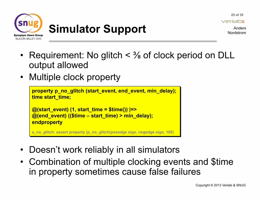
• Requirement: No glitch < ⅜ of clock period on DLL output allowed
• Multiple clock property
• Doesn’t work reliably in all simulators • Combination of multiple clocking events and $time
in property sometimes cause false failures
property p_no_glitch (start_event, end_event, min_delay); time start_time; @(start_event) (1, start_time = $time()) |=> @(end_event) (($time – start_time) > min_delay); endproperty a_no_glitch: assert property (p_no_glitch(posedge sigo, negedge sigo, 100)

26 of 35
Anders Nordstrom
Copyright © 2013 Verilab & SNUG
Simulator Support cont.
• Calculate pulse width using $time outside assertion
always @(posedge sigo) posedge_time = $time; always @(negedge sigo) negedge_time = $time; wire signed [31:0] period_delta = ((negedge_time - posedge_time) < 0) ? (posedge_time - negedge_time) : (negedge_time - posedge_time); a_no_glich: assert property (@(period_delta) (period_delta > sdll_width)) else ovm_report_error("SVA phy_sdll_assert", $psprintf("sdll %m sigo high or low period too short. Got %d Expected %d", $sampled(period_delta), sdll_width));
Recommendation 9: Avoid using $time directly inside assertions

27 of 35
Anders Nordstrom
Copyright © 2013 Verilab & SNUG
Clock Jitter Impact
• Requirement: Input clock (CK) to output clock (Y0) programmable offset tSTAOFF should be stable over PVT variations
JEDEC Standard No. xx-x - last edited: December 4, 2008 3:52 pmPage 54
PASS-HOLD
Figure 26 — Clock Output (Yn) Skew
Figure 25 — Definition for tstaoff and tdynoff
CK#
CK
Yn#
Yn
tstaoff(min)1
1. tstaoff = propagation delay for clock signal (rising CK input clock edge to rising Yn output clock edge).
tdynoff2
2. tdynoff = maximum tstaoff variation over voltage and temperature.
This includes all sources of jitter and drift (e.g.Thermal noise, supply noise, voltage/temperature drift, SSC tracking, SSO, etc) except reference clock noise.
tstaoff1
tstaoff(max)1
Y0#
Y0
Y2#
Y2
tCK
Y2#
Y2
tCKsk
tCKsk

28 of 35
Anders Nordstrom
Copyright © 2013 Verilab & SNUG
Clock Jitter Impact cont.
• Jitter on Y0, need to compare to range [ck2y_min : ck2y_max] – ck2y_min = ck2y – allowed_jitter – ck2y_max = ck2y + allowed_jitter
always @ (posedge CK) start_time = $time; a_tSTAOFF: assert property (@posedge Y0) disable iff (reset) ($time – start_time) == ck2y else ovm_report_error("SVA phy_assert", $psprintf("tSTAOFF (%t) is different than programmed value (%t)“, ($time – start_time), ck2y);
OVM_ERROR @ 236415.407 ns: reporter [SVA phy_assert] tSTAOFF (0.000 ns) is not between ck2y_min (1.793 ns) and ck2y_max (1.913 ns)

29 of 35
Anders Nordstrom
Copyright © 2013 Verilab & SNUG
Clock Jitter Impact cont.
• Clocks in Phase not considered – Fails for tSTAOFF == 0
• Jitter may cause order of edges to move • Need to consider two cases:
– Programmed offset greater than jitter (ck2y > jitter) – Programmed offset less than jitter (ck2y < jitter)
a_tSTAOFF: assert property (@(tSTAOFF) disable iff (reset) (tSTAOFF >= ck2y_min) && (tSTAOFF <= ck2y_max)) else ovm_report_error("SVA phy_assert", $psprintf("tSTAOFF (%t) is not between ck2y_min (%t) and ck2y_max (%t)", $sampled(tSTAOFF), ck2y_min, ck2y_max));

30 of 35
Anders Nordstrom
Copyright © 2013 Verilab & SNUG
Clock Jitter Impact cont.
• Case 1: Programmed offset > allowed jitter
• Y0 edge between A and B
31 of 35
Anders Nordstrom
Copyright © 2013 Verilab & SNUG
Clock Jitter Impact cont.
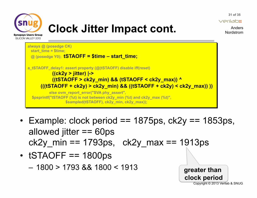
• Example: clock period == 1875ps, ck2y == 1853ps, allowed jitter == 60ps ck2y_min == 1793ps, ck2y_max == 1913ps
• tSTAOFF == 1800ps – 1800 > 1793 && 1800 < 1913
always @ (posedge CK) start_time = $time; @ (posedge Y0); tSTAOFF = $time – start_time; a_tSTAOFF_delay1: assert property (@(tSTAOFF) disable iff(reset) ((ck2y > jitter) |-> ((tSTAOFF > ck2y_min) && (tSTAOFF < ck2y_max)) ^ (((tSTAOFF + ck2y) > ck2y_min) && ((tSTAOFF + ck2y) < ck2y_max)) )) else ovm_report_error("SVA phy_assert", $psprintf("tSTAOFF (%t) is not between ck2y_min (%t) and ck2y_max (%t)", $sampled(tSTAOFF), ck2y_min, ck2y_max));
greater than clock period
32 of 35
Anders Nordstrom
Copyright © 2013 Verilab & SNUG
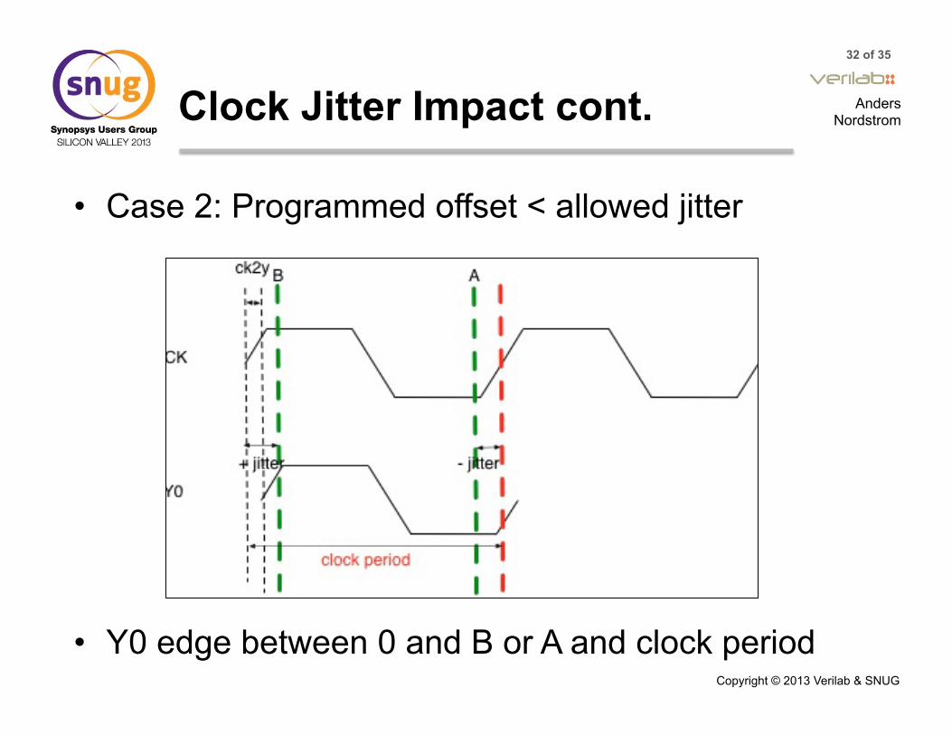
Clock Jitter Impact cont.
• Case 2: Programmed offset < allowed jitter
• Y0 edge between 0 and B or A and clock period

33 of 35
Anders Nordstrom
Copyright © 2013 Verilab & SNUG
Clock Jitter Impact cont.
• Example: clock period == 1875ps, ck2y == 50ps allowed jitter == 60ps ck2y_min == -10ps, ck2y_max == 110ps
• tSTAOFF == 70ps – 70 >= 0 && 70 < 110
a_tSTAOFF_delay2: assert property (@(tSTAOFF) disable iff(reset) ((ck2y <= jitter) |-> ((tSTAOFF >= 0) && (tSTAOFF < ck2y_max)) ^ ((tSTAOFF > (sim_period - ck2y_min)) && (tSTAOFF < sim_period)) )) else ovm_report_error("SVA phy_assert", $psprintf("tSTAOFF (%t) is not between 0 and ck2y_max (%t) or ck2y_min (%t) and sim_period (%t)", $sampled(tSTAOFF), ck2y_max, ck2y_min, sim_period));
Recommendation 10: Consider all cases of clock phases with jitter – separate assertions
Y0 edge before CLK edge

34 of 35
Anders Nordstrom
Copyright © 2013 Verilab & SNUG
Conclusions
• SVA successfully used to verify DDR3 functional timing
• Found bugs missed in OVM only simulations • Several issues encountered
– Integrating with OVM – SVA behavior – DUT behavior e.g. jitter
• 10 recommendations developed
35 of 35
Anders Nordstrom
Copyright © 2013 Verilab & SNUG
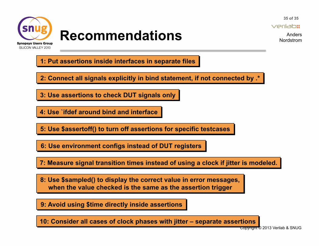
Recommendations 1: Put assertions inside interfaces in separate files
2: Connect all signals explicitly in bind statement, if not connected by .*
5: Use $assertoff() to turn off assertions for specific testcases
3: Use assertions to check DUT signals only
4: Use `ifdef around bind and interface
6: Use environment configs instead of DUT registers
7: Measure signal transition times instead of using a clock if jitter is modeled.
8: Use $sampled() to display the correct value in error messages, when the value checked is the same as the assertion trigger
9: Avoid using $time directly inside assertions
10: Consider all cases of clock phases with jitter – separate assertions


