73
SUBCOURSE EDITION SS 0029 B US ARMY SIGNAL CENTER AND FORT GORDON PLAN TACTICAL TELEPHONE SYSTEMS
| Date post: | 13-Apr-2018 |
| Category: |
Documents |
| Upload: | truonghuong |
| View: | 225 times |
| Download: | 0 times |

SUBCOURSE EDITION
SS 0029 B
US ARMY SIGNAL CENTER AND FORT GORDON
PLAN TACTICAL TELEPHONESYSTEMS

PLAN TACTICAL TELEPHONE SYSTEMS
Subcourse Number SS 0029
EDITION B
United States Army Signal Center and Fort GordonFort Gordon, Georgia 30905-5000
2 Credit Hours
Edition Date: September 1994
SUBCOURSE OVERVIEW
This subcourse is designed to teach you the basic procedures involved in planning tactical telephone systems, including trunk group sizing, the joint operations numbering systems, and the telephone directory.
The prerequisite for this subcourse is that you be a graduate of the Signal Officer's Basic Course.
This subcourse reflects the doctrine which was current at the time it was prepared. In your own work situation, always refer to the latest official publications.
Unless otherwise stated, the masculine gender of singular pronouns is used to refer to both men and women.
TERMINAL LEARNING OBJECTIVE
ACTION: Describe the tactical telephone systems supporting a maneuver division or corps.
CONDITION: Given this subcourse.
STANDARD: To demonstrate competency of this task, a minimum of 70 percent on the subcourse examination must be achieved.
i SS 0029
TABLE OF CONTENTS
Section Page
Subcourse Overview..................................................................................................................................... i
Lesson 1: Tactical Telephones and Switchboards............................................................................ 1-1
Part A: Telephones .....................................................................................................1-6
Part B: Switchboards................................................................................................ 1-14
Practice Exercise...........................................................................................1-30
Answer Key and Feedback........................................................................... 1-32
Lesson 2: Tactical Numbering System............................................................................................. 2-1
Practice Exercise.............................................................................................2-8
Answer Key and Feedback........................................................................... 2-10
Lesson 3: Introduction to Trunk Group Sizing................................................................................. 3-1
Part A: Definitions...................................................................................................... 3-2
Part B: Small Extension Switch (Example) ...............................................................3-4
Practice Exercise...........................................................................................3-17
Answer Key and Feedback........................................................................... 3-18
Lesson 4: Telephone Directory.........................................................................................................4-1
Practice Exercise.............................................................................................4-6
Answer Key and Feedback............................................................................. 4-8
SS 0029 ii

Section Page
Appendix A: Tactical Telephone and Switchboard Configurations .......................................................A-1
Appendix B: Tactical Telephone Subscriber Information.......................................................................B-1
Appendix C: Acronyms and Abbreviations ............................................................................................C-1
iii
LESSON 1
TACTICAL TELEPHONES AND SWITCHBOARDS
Critical Task: 01-5710.07-0001
OVERVIEW
LESSON DESCRIPTION:
In this lesson, you will learn the different telephones and switchboards used by the Army in support of a division, corps, or echelon above corps (EAC).
TERMINAL LEARNING OBJECTIVE:
ACTION: Describe the different tactical telephones and switchboards.
CONDITION: You will have this lesson material, paper, pencil, and no supervision
STANDARD: To demonstrate competency on this lesson, you must achieve a minimum of 70 percent on the subcourse examination.
INTRODUCTION
Today, the Army uses many different types of telephones and switchboards. The mission involved and units employed will determine the equipment requirements and their reconfigurations.
1. Types of telephones. We can divide the tactical telephones into two major groups-common-battery and local-battery equipment. Normally, units at company and battalion level use local-battery equipment. At the brigade level and up, we use common-battery equipment. Table 1-1 provides a list of the telephones and switchboards most commonly used. Part A of this lesson provides their technical characteristics.
1-1 SS 0029

Table 1-1. Tactical telephones and switchboards.
a. Local-battery telephones.
(1) TA-1/PT is a lightweight, waterproof, sound-powered telephone. It is found at the infantry squad level. The TA-1 telephone can interface with any battery-powered telephone or switchboard. The infantry squads used the TA-1/PT for internal communications and to link with the platoon headquarters element (See Appendix A, Figure A-1.)
(2) TA-312/PT is a 2-wire battery-operated field telephone. It can operate both in the local-battery or common-battery mode. The units can use the TA-312/PT or the TA-43/PT in a point-to-point wire system or in any 2-wire ringdown communication system. The TA-312/PT and the TA-43/PT are the two primary telephones used by the maneuver battalions. (See Appendix A, Figure A-2.)
(3) TA-341/TT is a 4-wire telephone. It can operate on local-battery or common-battery mode. The TA-341/TT can be used with an automatic analog switchboard or in a point-to-point configuration. Most of the TA-341/TTs found today are assigned to the Reserve Components. Initially, the TA-341/TT telephones were issued to Corps Area Signal Battalion with the AN/TTC-38 switchboard. (See Appendix A, Figure A-3.)
SS 0029 1-2

b. Common-battery telephones.
(1) TA-838/TT is a rugged, solid-state field telephone It is used with the SB-3614 switchboard. It can also be used with the AN/TTC-38, AN/TTC-39, and AN/TTC-S9A. When using the TA-838/TT in the 4-wire mode, it can have up to three extensions on one phone. When we use the TA-838/TT in the 2-wire mode, we can only have one extension from one telephone. (See Appendix A, Figure A-4.)
(2) TA-938/G is a 2-wire common-battery telephone set intended for use in a sheltered area. You can bridge two sets across a single 2-wire line for extension service. (See Appendix A, Figure A-5.)
(3) TA-954/TT is a 4-wire terminal. The TA-954/TT can send and receive conditioned diphase-modulated digitized voice. It can send and receive information at 16 or 32 kb/s rate. The TA-954/TT provides digital communications interface with the joint communications (TRI-TAC) and mobile subscriber equipment (MSE) switchboards (See Appendix A, Figure A-6.)
(4) TSEC/KY-68 digital subscriber voice terminal (DSVT) provides encryption/decryption voice traffic service. It can also provide secure digitized data traffic service. The TSEC/KY-68 operates as a full-duplex or half-duplex terminal. The TSEC/KY-68 provides secure and nonsecure access to switched networks. (See Appendix A, Figure A-7.)
(5) TA-1035/U digital nonsecure voice terminal (DNVT) provides full-duplex, conditioned diphase-modulated digital voice service. It can also provide loop signaling information with wire and mobile access equipment. The TA-1035/U provides a data port for interfacing the SST and AN/UXC-7A devices. (See Appendix A, Figure A-8.)
2. Types of switchboards.
a. Tactical switchboards are divided into two major groups-manual battery and common-battery equipment. At brigade level and up, we find common-battery equipment housed in mobile units.
b. The mobile units get prewired and designed to accommodate the equipment needed for the mission. The shelter has cable receptacles for connecting the 26-pair field cables. They usually contain electrical heaters to warm the personnel and equipment during cold weather. A trailer-mounted power-generating unit provides electrical power to the shelter. The next few subparagraphs examines the different switchboards found in the field.
(1) SB-993/PT is 6-line analog 2-wire manual switchboard, capable of supporting a maximum of six local-battery telephone circuits or six trunk circuits. (See Appendix A, Figure A-9.)
1-3 SS 0029

(2) SB-22/PT and SB-22A/PT are tactical manual switchboards They can provide service to 12 local-battery telephone circuits. The operator can stack two SB-22s to support up to a 29-circuit system. To support 29 subscribers, the operator must remove the operator pack from the second SB-22. He then installs a 5-line pack. To interface with the automatic switches, the operator must install a TA-997/PT or tone-signaling adapter. No operator intervention is required when using the tone-signaling adapter. (See Appendix A, Figure A-10.)
(3) SB-3082(V) /GT can service up to 50 telephone circuits. The SB-3082 can be mounted on a 1/4-ton truck or in a shelter. The operator can set up a conference call for up to six subscribers. The switchboard has an emergency power system. The emergency power system runs on two 12-volt batteries. In addition, the switchboard brings a battery charger for recharging the emergency system. (See Appendix A, Figure A-11.)
(4) AN/TTC-38 can interconnect 300 or 600 telephone circuits. We can find the AN/TTC-38 deployed in an area communications center (ACC). The AN/TTC-38 is all analog. The primary telephones used with the AN/TTC-38 are the TA-341, TA-838, and the TA-938. Today, we find most of the AN/TTC-38s still in service with the Reserve Component units. (See Appendix A, Figure A-14.)
(5) AN/TTC-39A and AN/TTC-39D can service 600 or 672 trunks depending on the model on hand. The AN/TTC-39A provides, for the first time, the capability of miring analog and digital service. It can interface with existing tactical switches (manual and automatic), commercial central offices, and Defense Switched Network (DSN). In addition, the AN/TTC-39A and AN/TTC-39D can interface with North Atlantic Treaty Organization (NATO) telephone systems. We find the AN/TTC-39D at EAC. (See Appendix A, Figures A-15a through A-15d.) The AN/TTC-39A is found in Army Reserve EAC units, Air Force units, and the Joint Communications Support Element.
(6) AN/TTC-41 and AN/TTC-41A is an automatic switchboard. The AN/TTC-41 comes in several models. The AN/TTC-41(V) 1 can service up to 30 subscribers; the models V2 and V5 can service up to 60 subscribers; the models V3 and V6 can service up to 90 subscribers; and the AN/TTC-41A (V) 4 and 7 can service up to 120 subscribers. (See Appendix A, Figure A-16.) The AN/TTC-41A can interface with the DSN and dial central offices (DCOs). The switchboard is capable of providing 2- or 4-wire service.
(7) AN/TTC-46 or large extension node (LEN) switchboard has basically the same configuration as the node center switch (NCS)(AN/TTC-47). The basic difference is the termination configuration for trunks and loops. The LEN doctrinally is deployed in support of the division support command (DISCOM) in an MSE division. It can support a total of 164 subscribers using J-1077 and remote multiplexer combiners (RMCs). (See Appendix A, Figures A-17a and A-17b.)
(8) AN/TTC-47 or NCS is the hub of the MSE node. The AN/TTC-47 provides network interface for the subscriber access elements. The AN/TTC-47 provides automatic subscriber finding, deleting the need for knowledge of the subscribers' geographical location. (See Appendix A, Figures A-18a and A-18b.)
SS 0029 1-4

(9) AN/TTC-48 or small extension node (SEN) switch contains both switching and packet switching equipment. The communications security (COMSEC) equipment provides secure digital communications to a command post (CP). The SEN is doctrinally deployed in support of the maneuver brigades. The SENs come in two versions. The SENs can provide two DCO circuits and net radio interface (NRI) via the KY-90. We can use CX-11230 cable and line-of-sight (LOS) to interface with the node center (NC) and LEN. A planner can also interface an NC or LEN using a tactical satellite (TACSAT) terminal. There are no non-MSE divisions in the Army or National Guard. (See Appendix A. Figure A-19.)
1-5 SS 0029

PART A - TELEPHONES
1. TA-1/PT telephone set.
Status: STD-A; NSN: 5805-00-521-1820
General Information
The TA-1/PT is a lightweight, weatherproof, sound-powered telephone intended for use on field-wire lines in forward areas. It can be used for communications with any local battery field telephone or local battery switchboard. It includes a generator for producing 20-Hz ringing current.
Technical Characteristics
Range..................................................................................... Approximately 6 km (3.7 mi)using field wire WD-1/TT (10 dBworking limit)
Type of Operation..................................................................Local batterySignaling Voltage ..................................................................65 to 80 V AC, 20 HzType of signaling:Visual .................................................................................. Nonadjustable Maltese crossAudible ................................................................................Buzzer, adjustable from LOUD to
OFFPower Requirement ...............................................................NoneWeightTelephone ............................................................................1.25 kg (2.75 lbs)Carrying case ...................................................................... .0.4 kg (14 oz)
SS 0029 1-6

2. TA-312/PT and TA-43 PT telephone sets.
Status: STD-A; NSN: 5805-00-543-0012 (TA-312/PT)STD-B; NSN: 5805-00-503-2775 (TA-43/PT)
General Information
The TA-312/PT and TA-43/PT are 2-wire, battery-operated field telephone They can be utilized in a point-to-point wire system or in any 2-wire ringdown subscriber position of a telephone communications system. The handset H-60 contains a PUSH-TO-TALK switch which connects power for talking. The TA-312/PT has a built-in receptacle connector U-79/U for use with a headset and an associated EXT-INT switch; the TA-43/PT does not. The TA-43/PT is being replaced by the TA-312/PT. TA-955 dual tone multifrequency (DTMF) adapter, allows pushbutton operational interface with automatic analog switches.
Technical Characteristics
Range:Wet.......................................................................................Approximately 22.5 km (14 mi) on
WD-1/TT. (36 dB working limit)Dry....................................................................................... Approximately 36.4 km (22 mi) on
WD-1/TT (36 dB workinglimit)
Type of Operation:Common Battery..................................................................Voice transmission and signaling
power supplied by switchboardLocal battery........................................................................ Voice transmission power supplied
by two BA-30s, signaling power issupplied by a hand-crankgenerator
Common-BatterySignaling.............................................................................. Signaling power supplied by
switchboard, voice transmissionprovided by two BA-30s
Signaling (Outgoing)........................................................... Hand generated, 90 to 100 V AC,20 Hz
Signaling (Incoming)........................................................... Audible tone, adjustable volume
1-7 SS 0029

3. TA-341/TT telephone set.
Status: STD-A; NSN: 5805-00-910-8844
General Information
The TA-341/TT is a 4-wire, transistorized, local-battery telephone intended for use in sheltered areas. It is designed for use with tactical automatic switches but can also be used in a point-to-point mode. Up to four sets can be bridged across a single 4-wire line for extension service. DTMF tones activated by a pushbutton key sender are used for signaling.
Technical Characteristics
Range .................................................................................... 3 m (2 mi) from AN/TTC-38under the worst conditions
Type of Operation: ................................................................Local or common batterySignaling (Outgoing) ............................................................ 900 to 3400 Hz DTMFSignaling (Incoming) ............................................................ 90 V AC, 20 HzType of Signal .......................................................................Audible tone, adjustable volumePower Requirement................................................................6 V DC (four BA-42s or
equivalent)Weight ...................................................................................3.2 kg (7 lbs)
SS 0029 1-8

4. TA-838/TT telephone set
Status: STD-A; NSN: 5805-00-124-8678
General Information
The TA-838/TT is a rugged, solid-state field telephone designed for use with switchboards SB-3614/TT and SB-3614/AT or with the tactical automatic switches AN/TTC-25, AN/TTC-38, AN/TTC-39, and AN/TT-39A and is capable of compatible interoperation with TA-341/TT and C-6709 (NRI) equipment. It is a 2- or 4-wire local or common-battery set using DTMF tones for signaling and will work with any DTMF semiautomatic or automatic circuit. Using the TA-838/TT, up to three extensions may be added in the 4-wire mode and only one extension may be used in the 2-wire mode.
Technical Characteristics
Range .................................................................................... 3.2 km (2 mi) from SB-3614/TTunder the worst conditions
Type of Operation .................................................................Local or common batterySignaling (Outgoing) ............................................................ 900 to 3400 Hz DTMFSignaling (Incoming) ............................................................ 90 V AC, 20 HzType of Signal .......................................................................Audible tone, adjustable volumePower Requirement ...............................................................6 V DC (four BA-42s or BA-2042s)Weight ...................................................................................3.6 kg (8 lbs)
1-9 SS 0029

5. TA-938/G telephone set
Status: STD-A; NSN: 5805-00-134-2599
General Information
The TA-938/G is a 2-wire common-battery telephone set intended for use in sheltered areas. The telephone set uses DTMF signaling. Two sets can be bridged across a single 2-wire line for extension service.
Technical Characteristics
Range..................................................................................... Approximately 8 km (5 mi) fromthe DCO
Type of Operation .................................................................Common batterySignaling Voltage...................................................................90 V AC, 20 HzType of Signal .......................................................................BellPower Requirement ...............................................................Supplied by the DCOWeight ...................................................................................1.8 kg (4 lbs)
SS 0029 1-10

6. TA-954/TT DNVT.
Status: STD-A; NSN: 5805-01-159-9691
General Information
The DNVT TA-954/TT is a 4-wire terminal contained in a ruggedized case, which transmits and receives conditioned diphase-modulated digitized voice and loop signaling information at 16 kb/s or 32 kb/s. The DNVT has a 16-key pushbutton keyboard, receiver and ring volume controls, an incoming call/off-hook indicator light, and writing pad. It contains a built-in protection from nuclear energy electromagnetic pulses and lightning. Handset H-350/U is issued with the DNVT. The microphone element is activated when the handset is removed from the cradle (hot mike). The PUSH-TO-NRI switch is only pressed to key the C-6709. The DNVT provides a digital communications interface with TRI-TAC and MSE circuit switches.
Technical Characteristics
Channel Interface-Field Wire ............................................... 4-wire field cableTransmission Range ..............................................................4 km (2.4 mi) maxInput Power-Power DrainOn Hook ..............................................................................300 mW, maxOff Hook.............................................................................. 1.5 W, max
Power Requirement ...............................................................+24 to +56 V DCCurrent Drain:On Hook ..............................................................................12.5 mA, +24 V DC
5 mA, +56 V DCOff Hook ............................................................................. 62 mA, +24 V DC
25 mA, +56 V DCWeight ...................................................................................2.7 kg (5.8 lbs)
1-11 SS 0029

7. TSEC/KY-68 digital subscriber voice terminal.
Status: STD-A; NSN: 5810-01-082-8404
General Information
The DSVT KY-68 is used for encrypting/decrypting voice traffic and provides secure digitized data traffic. It operates as a full-duplex or half-duplex voice/data subscriber terminal at 16 to 32 kb/s. The KY-68 provides secure and nonsecure access to the switched networks and secure access to nonswitched networks. Handset H-350/U is normally issued with the DSVT and includes a PUSH-TO-TALK switch which is used when the DSVT is operating in the half-duplex mode to allow for voice transmission. The terminal consists of a five-position function switch, audio and ring volume controls, ring/busy, extension, and nonsecure warning indicators. The DSVT provides a digital communications interface with TRI-TAC and MSE circuit switches. The DSVT KY-68 also has a data port for interfacing the communications terminal (CT) and AN/UXC-7.
Technical Characteristics
Channel Interface-Field Wire ............................................... 4-wire field cablePower Requirement................................................................-21 to -56 V DC (DC voltage is
provided by the auxiliary powersupply HYP-71/TSEC)
Weight....................................................................................6.3 kg (14 lbs)
SS 0029 1-12

8. TA-1035/U DNVT.
Status: To be determined; NSN: 5805-01-246-6826
General Information
As a prime subscriber terminal, the TA-1035/U provides fill-duplex, conditioned, diphase digital voice and loop signaling information with wire and mobile access equipment. It also provides supervisory, clock, plain text, and voltage reference signals with data devices. The TA-1035/U provides a data port for interfacing the CT and AN/UXC-7 data devices to the MSE network. The TA-1035/U operates in a common-battery power mode, deriving its power from the switch line termination circuit.
Technical Characteristics
Power Requirements.............................................................. 48 V DCPower Consumption:Off-Hook (Powered Up)...................................................... 1.5 W (max)On-Hook (Powered Down)..................................................300 mW (max)
1-13 SS 0029

PART B - SWITCHBOARDS
9. SB-993/GT manual telephone switchboard.
Status: STD-A; NSN: 5805-00-708-2202
General Information
The SB-993/GT is a lightweight, portable switchboard capable of handling six local-battery telephone lines. It is designed for use in forward combat areas. It requires the use of either a local-battery telephone or a sound-powered telephone (not a component).
Technical Characteristics
Type of Operation..................................................................Manual with local batteryLine Capacity.........................................................................1 operator line and 6 local-battery
circuitsSignaling (Outgoing) ............................................................ 90 V AC, 20 HzSignaling (Incoming)............................................................. 90 V AC, 20 HzType of Signal .......................................................................Neon glow lampPower Requirement................................................................NoneWeight ...................................................................................2.04 kg (4.5 lbs)
SS 0029 1-14

10. SB-22/PT and SB-22A/PT manual telephone switchboards
Status: STD-A; NSN: 5805-00-257-3602 (SB-22/PT)STD-A; NSN: 5805-00-715-6171 (SB-22A/PT)
General Information
The SB-22/PT and the SB-22A/PT are tactical manual switchboards that can be rapidly installed to provide field facilities for interconnecting 12 local-battery telephone circuits, remote controlled radio circuits, or voice frequency (VF) teletypewriter circuits. Two SB-22/PTs may be stacked to provide a 29-circuit capability by removing one TA-221/PT (operator's pack) and inserting five TA-222/PTs (line packs). Replacing a line pack with a trunk pack permits one-way ringdown and one-way automatic trunk circuits between the SB-22A/PT and any other switchboard with common-battery signaling. Tone-signaling adapter TA-977/PT provides the operator with a 2-wire pushbutton tone-signaling capability for interfacing automatic switches without operator intervention.
Technical Characteristics
Type of Operation .................................................................Manual with local batteryLine Capacity ........................................................................12Signaling (Outgoing) ............................................................ 90 to 100 V AC, 20 HzSignaling (Outgoing) w/Adapter ...........................................DTMFSignaling (Incoming) ............................................................ 90 V AC, 20 HzType of Signal .......................................................................Audible or visual alarmPower Requirement:Operator's Talking Circuit .................................................. 3 V DC (two BA-30s)Night Alarm and Panel Light ..............................................3 V DC (two BA-30s)
Weight ...................................................................................15.4 kg (34 lbs)
1-15 SS 0029

11. SB-3082(V)1/GT cordless manual telephone switchboard.
Status: STD-B; NSN: 5805-00-235-5035
General Information
The SB-3082(V) 1/GT is a 50-termination telephone switchboard that can be mounted in a 1/4-ton truck or in a shelter. The switchboard has no cords and connections are made by pushbutton switches. The operator can connect any two terminations, can perform preemption of any termination in use, and can establish a conference for up to six subscribers. The switchboard includes a battery charger to keep the two 12-volt emergency batteries charged.
Technical Characteristics
Type of Operation .................................................................Manual with local- or common-battery signaling
Line Capacity ........................................................................50Common-Battery Signaling/Common Battery/20-Hz Ringdown Line/Trunk ............................................Any of the 50
1600 Hz Ringdown Trunk .................................................. 1 through 24 onlyTactical Automatic Switch Trunk .......................................1 through 24 onlyDC Closure Civilian Lines...................................................47 through 50 only
Signaling (Outgoing)............................................................. 90 V AC, 20 Hz or 1600 HzSignaling (Incoming) ............................................................ 90 V AC, 20 Hz or 1600 HzType of Signal .......................................................................Audible tone and lampPower Requirement ...............................................................105 to 125 V AC, 50, 60, or
400 Hz or +12 V DC and -12 V DC(24 V DC center tapped)emergency use only
Weight ...................................................................................127 kg (280 lbs)
SS 0029 1-16
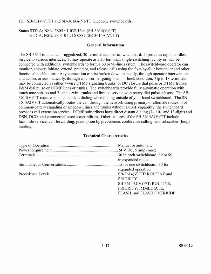
12. SB-3614(V)/TT and SB-3614A(V)/TT telephone switchboards.
Status STD-A; NSN: 5805-01-032-1694 (SB-3614(V)/TT)STD-A; NSN: 5805-01-216-0887 (SB-3614A(V)/TT)
General Information
The SB-3614 is a tactical, ruggedized, 30-terminal automatic switchboard. It provides rapid, cordless service to various interfaces. It may operate as a 30-terminal, single-switching facility or may be connected with additional switchboards to form a 60 or 90-line system. The switchboard operator can monitor, answer, initiate, extend, preempt, and release calls using the four-by-four keysender and other functional pushbuttons. Any connection can be broken down manually, through operator intervention and action, or automatically, through a subscriber going to an on-hook condition. Up to 18 terminals may be connected as either 4-wire DTMF signaling trunks, or DC closure dial pulse or DTMF trunks, E&M dial pulse or DTMF lines or trunks. The switchboards provide fully automatic operation with touch tone subsets and 2- and 4-wire trunks and limited service with rotary dial pulse subsets. The SB-3614(V)/TT requires manual tandem dialing when dialing outside of your local switchboard. The SB-3614A(V)TT automatically routes the call through the network using primary or alternate routes. For common-battery signaling or ringdown lines and trunks without DTMF capability, the switchboard provides call extension service. DTMF subscribers have direct distant dialing (7-, 10-, and 13-digit) and DSN, DCO, and commercial access capabilities. Other features of the SB-3614A(V)/TT include facsimile service, call forwarding, preemption by precedence, conference calling, and subscriber (loop) hunting.
Technical Characteristics
Type of Operation .................................................................Manual or automaticPower Requirement ...............................................................24 V DC, 5 amp (max)Terminals .............................................................................. 30 in each switchboard; 60 or 90
in expanded modeSimultaneous Conversations .................................................15 for one switchboard; 30 for
expanded operationPrecedence Levels .................................................................SB-3614(V)/TT: ROUTINE and
PRIORITYSB-3614ACV) /7T: ROUTINE,PRIORITY, IMMEDIATE,FLASH, and FLASH OVERRIDE
1-17 SS 0029

Technical Characteristics (Cont)
Types of Terminal Printed Circuit Boards (PCB)..................Types I, II, III, IV,V, VI (SB-3614A(V)/TT only),and XI (SB-3614A(V)/TT only)
SS 0029 1-18
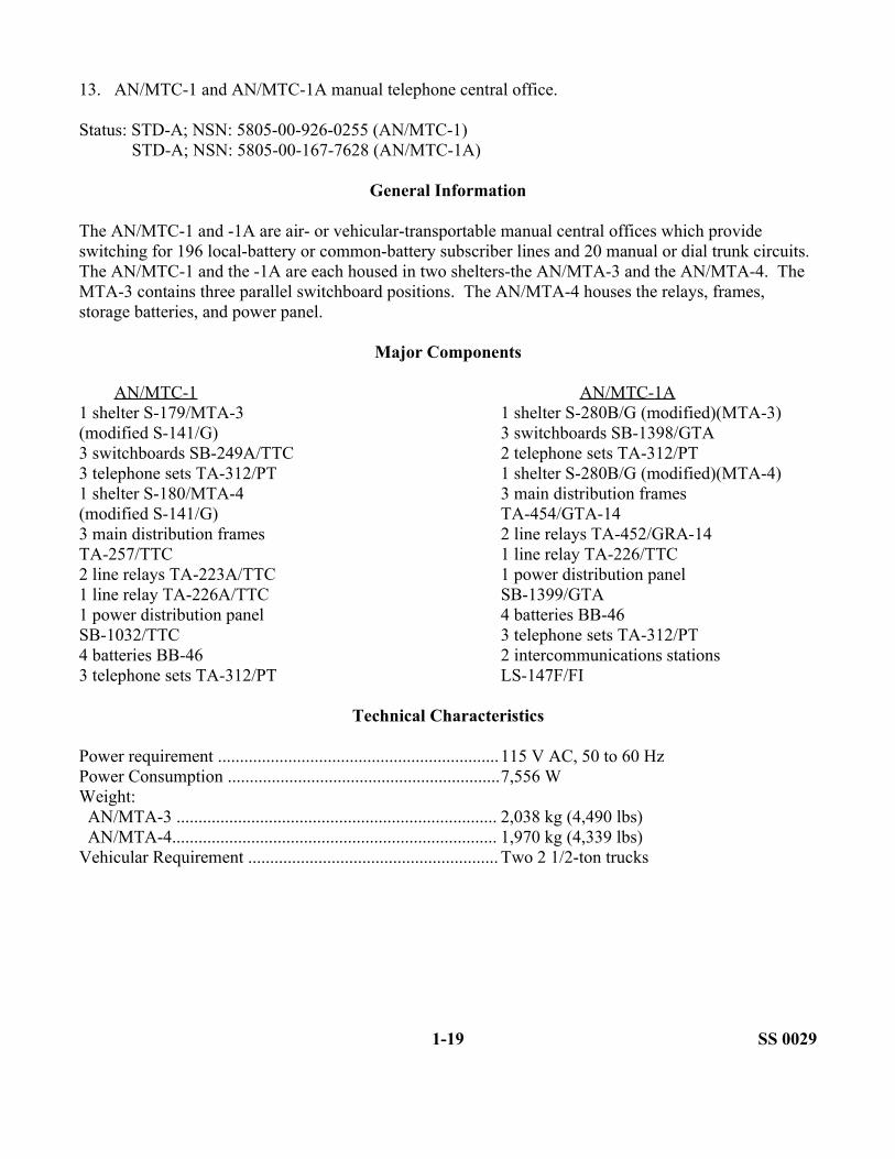
13. AN/MTC-1 and AN/MTC-1A manual telephone central office.
Status: STD-A; NSN: 5805-00-926-0255 (AN/MTC-1)STD-A; NSN: 5805-00-167-7628 (AN/MTC-1A)
General Information
The AN/MTC-1 and -1A are air- or vehicular-transportable manual central offices which provide switching for 196 local-battery or common-battery subscriber lines and 20 manual or dial trunk circuits. The AN/MTC-1 and the -1A are each housed in two shelters-the AN/MTA-3 and the AN/MTA-4. The MTA-3 contains three parallel switchboard positions. The AN/MTA-4 houses the relays, frames, storage batteries, and power panel.
Major Components
AN/MTC-1 AN/MTC-1A1 shelter S-179/MTA-3 1 shelter S-280B/G (modified)(MTA-3)(modified S-141/G) 3 switchboards SB-1398/GTA3 switchboards SB-249A/TTC 2 telephone sets TA-312/PT3 telephone sets TA-312/PT 1 shelter S-280B/G (modified)(MTA-4)1 shelter S-180/MTA-4 3 main distribution frames(modified S-141/G) TA-454/GTA-143 main distribution frames 2 line relays TA-452/GRA-14TA-257/TTC 1 line relay TA-226/TTC2 line relays TA-223A/TTC 1 power distribution panel1 line relay TA-226A/TTC SB-1399/GTA1 power distribution panel 4 batteries BB-46SB-1032/TTC 3 telephone sets TA-312/PT4 batteries BB-46 2 intercommunications stations3 telephone sets TA-312/PT LS-147F/FI
Technical Characteristics
Power requirement ................................................................115 V AC, 50 to 60 HzPower Consumption ..............................................................7,556 WWeight:AN/MTA-3 ......................................................................... 2,038 kg (4,490 lbs)AN/MTA-4.......................................................................... 1,970 kg (4,339 lbs)
Vehicular Requirement ......................................................... Two 2 1/2-ton trucks
1-19 SS 0029

14. AN/TTC-38(V)1 and AN/TTC-38(V)2 automatic telephone central offices.
Status: STD-A; NSN: 5805-00-186-0681 (AN/TTC-38(V)1)STD-A; NSN: 5805-00-186-0640 (AN/TTC-38(V)2)
General Information
The AN/TTC-38(V)1 and the AN/TTC-38(V)2 are air- or vehicular-transportable automatic central offices used to provide switching facilities in an area communications system They are capable of interconnecting either 300 (AN/TTC-38(V)1) or 600 (AN/TTC-38(V)2) VF or wideband telephone circuits. Each is installed in a shelter S-280/B. DTMF telephone sets TA-341/TT, TA-838/TT, or TA-938/G can be used with these central offices. The AN/TTC-38(V) includes the control test maintenance group OK-267(V)/TTC-38 which provides an enclosed area for the operation of a remote operator position of automatic telephone central office (AN/TTC-38(V) and maintenance test equipment used to perform the prescribed maintenance mission. The OK-267 is housed in shelter S-541/TTC-30(V).
Technical Characteristics
Power Requirement ...............................................................115/20 V AC; 3-phase; 4-wire; 50,60, or 400 Hz
Power Consumption:AN/TTC-38(V)1 ................................................................. 2,359 WAN/TTC-38(V)2 ................................................................. 2,624 W
Weight:AN/TTC-38(V)1.................................................................. 2,667 kg (5,875 lbs)AN/TTC-38(V)2 ................................................................. 3,151 kg (6,940 lbs)
Vehicular Requirement ......................................................... One 2 1/2-ton truck (TTC-38 )One 2 1/2-ton truck (OK-267)
SS 0029 1-20

15. AN/TTC-39A(V) 4 and AN/TTC-39D 712-line, and AN/TTC-39A(V) 3 300-line automatictelephone central office.
Status: STD-B; NSN: 5805-01-122-3414 (AN/TTC-39D)STD-B; NSN: 5805-01-121-4395 (AN/TTC-39A(V)3)STD-B; NSN: 5805-01-121-9560 (AN/TTC-39A(V)4)
General Information
The AN/TTC-39D and AN/TTC-39A(V)4 service up to 672 analog and digital loops/trunks at EAC. The AN/TTC-39 permits factory or depot level reconfiguration into a family of circuit switches containing various quantities, types, and mixes of analog and digital switching terminations. The AN/TTC-39A(V)3 performs like functions, but at a 600-line capacity. The AN/TTC-39 interfaces with DSN, automatic secure voice communications (AUTOSEVOCOM), existing tactical switches (manual and automatic), and commercial central offices. The AN/TTC-39 interfaces with NATO telephone systems using CV-3478. Up to three remote control call service positions supplement the call service function in the AN/TTC-39. It uses analog in-band, out-of-band digital (common channel), and dibits. It signals and supervises trunks and lines, including ringdown, DC closure, dial pulse, tone, or digital and provides a compatible connector between subscribers.
Major Components
712 Line 600 Line
1 switching module assembly 1 switching plus control1 storage shelter S-640 module assembly (combined)1 maintenance shelter S-639 S-250B/G (modified)1 master power distribution 1 maintenance shelter S-250unit ON-224/T 1 storage shelter S-250
2 electric power plants 1 master powerAN/MJQ-12 (60 kW) distribution unit ON-224/T
1 intershelter cable reeltrailer V-528/T
Technical Characteristics
Vehicular Requirements:39D, 39A(V) 4 ...................................................................... One 5-ton truck, two 2 1/2-ton
trucksA(V)3 .................................................................................... One or two CUCV or HUMMV
trucksPower Requirement ...............................................................115/208 V AC, 3-phase 50/60 Hz
((V) 4 at 400 Hz)
1-21 SS 0029

16. AN/TTC-39A(V)1 automatic telephone central office.
Status: STD-B; NSN: 5805-01-241-9710
General Information
The AN/TTC-39A(V) is modular/transportable switching communications and nodal control equipment that provides secure automatic switching and technical control for both digital and analog communications. It is a hybrid circuit switch with a 744-line capacity (96 analog and 648 digital). The facility provides technical control functions including channel reassignment and multiplexing, line testing, engineering orderwire, atomic timing standard, and analysis or trouble reports, alarms, and system data. It signals and supervises analog and digital trunks and lines. This includes 20-Hz/1600-Hz ringdown, DC closure, dial pulse, DTMF/multifrequency, and 6-wire E&M using tone burst, confirmation, nonconfirmation, common channel, and dibits signaling.
Major Components
1 switching module assembly 1 master power distribution unitS-280B/G (modified) ON-224T
1 storage shelter S-640 2 PU-406 electric power units1 maintenance shelter S-639 (30 kW) AN/MJQ-10A
Technical Characteristics
Total External Lines ..............................................................744Digital Matrix.......................................................................648Analog Matrix .....................................................................96
Maximum Local Loops/Trunks (within this total) ................240Digital Local Loops............................................................. 144Analog Local Loops/Trunks ............................................... 96
Maximum Analog Loops via DTGs ..................................... 60Switch Rate ........................................................................... 16/32 kb/sTotal DTGs ........................................................................... 30Maximum Channels Per DTG............................................... 144In-Band Digital Trunks (Long Loops)...................................200Call Rate ................................................................................7,500 (calls per busy hour)Analog Bandwidth ................................................................ 108 kHzNumbering Plan .................................................................... TRI-TAC NATO, 13 digits;
military tactical, 7 digits;DSN, 10 digits
Power .................................................................................... 120/208 V AC; 50, 60, 400 Hz;three-phase
Vehicle Requirements ...........................................................One 5-ton truck (TTC39A);2 1/2-ton trucks (S-640)(S-639)
SS 0029 1-22

17. AN/TTC-41( ) automatic telephone central office.
Status: STD-A; NSN: 5805-01-028-8393 (AN/TTC-41(V)1)STD-A; NSN: 5805-01-028-8394 (AN/TTC-41(V)2)STD-A; NSN: 5805-01-028-8392 (AN/TTC-41(V)3)STD-A; NSN: 5805-01-044-8869 (AN/TTC-41(V)4)STD-A; NSN: 5805-01-044-8870 (AN/TTC-41(V)5)STD-A; NSN: 5805-01-045-3157 (AN/TTC-41(V)6)STD-A; NSN: 5805-01-044-8871 (AN/TTC-41(V)7)
General Information
The AN/TTC-41 is an air- or vehicular-transportable assemblage used to provide rapid automatic switching to tactical units in an area-type communications system. The AN/TTC-41( ) provides cordless service to 2-wire common-battery signaling lines, 20-Hz ringdown lines or trunks, common-battery dial pulse or DTMF lines, and 4-wire tone signaling trunks. The AN/TTC-41(V) 1 provides 30 lines of service in a shelter configuration. The AN/TTC-41(V) 2 and AN/TTC-41(V) 5 provide 60 lines of service. The AN/TTC-41(V) 3 and AN/TTC-41(V) 6 provides 90 lines of service. The AN/TTC-41(V) 4 and AN/TTC-41(V) 7 provides 120 lines of service in a shelter configuration. The (V) 1 through (V) 4 models are shelter configurations and (V) 5 through (V) 7 are trailer configurations.
Major Components
1 shelter S-561 1 telephone set TA-938/G pushbuttonTTC-41( )(modified shelter (all models)S-250/G)((V)1-(V)4 models) 1 through 5 switchboards
1 trailer assembly V-498/TTC-41(V) SB-3614(V)/TT or SB-3614A(V)/TT and(modified trailer M-569)((V) -5-(V) 7 headset H-182/PT (depending on themodels) model)
1 intercommunications station 1 or 2 power suppliesLS-147F/FI (All models) PP-6224/U (depending on the model)
1 headset switchbox (all models)
Technical Characteristics
Power Requirement ...............................................................115 V AC; 60 Hz; single phasePower Consumption:(V)1 .....................................................................................5.1 kW, 1,031 kg (2,270 lbs)(V)2 .....................................................................................5.2 kW, 1,058 kg (2,330 lbs)(V)3 .....................................................................................5.3 kW, 1,090 kg (2,400 lbs)(V)4 .....................................................................................6.5 kW, 1,167 kg (2,570 lbs)(V)5 .....................................................................................2.1 kW, 945 kg (2,080 lbs)(V)6 .....................................................................................2.2 kW, 963 kg (2,120 lbs)(V)1 .....................................................................................3.5 kW, 1,050 kg (2,310 lbs)
1-23 SS 0029

Technical Characteristics (Cont)
Vehicular Requirement.......................................................... 1 1/4-ton truck (V)1-(V)4, one 1/4-tontruck, and one 3/4-ton truck
SS 0029 1-24

18. AN/TTC-46 large extension node switch.
Status: To be determined; NSN: To be determined
General Information
The large extension node switch (LENS) is configured in two S-250( )/G-the ON-305/TTC-46 switching shelter and the OL-412/TTC-46 operations shelter. Each shelter is transported to an M-1037 high mobility multipurpose wheeled vehicle (HMMWV). The LENS is configured basically the same as the NC switch with the basic difference in termination configuration for trunks and loops. The switching shelter provides the external interface, circuit switching, and associated functions. The operations shelter provides the central processing and operator interface functions. Power to both assemblages is provided by a PU-753/M, 10-kW, trailer-mounted, diesel generator towed by the operations shelter's prime mover.
Major Components
ON-305 OL-412Shelter S-250/G 1Shelter S-250E/G 1Switch subsystem AN/TTC-46:LCSP* 1Switching processor subsystem* 1Plasma display unit* 1TDSGM
STED KG-194A 3Loop key generator KG-112 8Automatic key distribution control KGX-93 1Transition unit HGF-93 1Net control device KYX-15 1Communications modem 1VINSON COMSEC KY-57 1Secure device NRI KY-90 1Environmental control unit 1Junction box J-1077/U 8Intercommunications station LS-147 1Workstation (UXC-86) 1DNVT TA-1035/U 1Super high frequency (SHF) control unit 2Signal cable CX-4566 2Intershelter cables 6Power cables CX-7453 and CX-7705** 1Packet switch AN/TYC-20 2
* Part of AN/TTC-46
1-25 SS 0029

Technical Characteristics
Power Requirements ............................................................. 115 V AC, 50 or 60 Hz, singlephase
Channel Rates........................................................................ 16 kb/sDigital Terminations.............................................................. 648Trunk Signaling Buffers........................................................ 4Digital Inband Signaling Buffers ..........................................4Digital Transmission Groups ................................................ 8Digital Receivers....................................................................20Digital Loops......................................................................... 84Analog Loop (Commercial Interface)....................................4Conference Bridge Unit......................................................... 4
SS 0029 1-26

19. AN/TTC-47 NCS.
Status: To be determined; NSN: To be determined
General Information
The NCS is configured in two S-250( )/G shelters-a wit g shelter and an operations shelter, each transported on an M-1037 (HMMWV). The NCS is the hub of the MSE node providing network interface for the subscriber access elements. The ON-306/TTC-47 switching shelter provides the external interface, circuit switching, and associated functions. The OL-413/TTC-47 operations shelter provides the central processing and operator interface functions. The NCS provides automatic subscriber finding features which allow permanent subscriber address assignment and negates the need for knowledge of subscriber geographical location and switch affiliation at the subscriber level. Power to both assemblages is provided by a PU-753/M, 10-kW, trailer-mounted, diesel generator.
Major Components
ON-306 OL-413Shelter S-250/G 1Shelter S-250E/G 1Switch subsystem AN/TTC-47:LCSP* 1Switching processor system* 1Plasma display unit* 1TDSGM 2
Trunk encryption device KG-194A's 15Loop key generator KG-112 8Automatic key distribution control KGX-93 1Transition unit HGF-93 1Net control device KYX-15 1Communication modem 1VINSON COMSEC KY-57 1Environmental control unit 1Junction box J-1077/U 2Intercommunications station LS-147 1 1Workstation 1DNVT TA-1035/U 1Signal cable CX-4566 2Intershelter cables 6Power cables CX-7453 and CX-7705 ** 1Packet switches AN/TYC-19 and -20 1
* Part of AN/TTC-47
** Shelter power cables are connected in series
1-27 SS 0029

Technical Characteristics
Power Requirements ............................................................. 115 V AC, 50 or 60 Hz, singlephase
Channel Rates ....................................................................... 16 kb/sDigital Terminations ............................................................. 648Trunk Signaling Buffers........................................................ 8Digital Inband Signaling Buffers ..........................................10Digital Transmission Group...................................................16Digital Receivers ...................................................................20Digital Loops ........................................................................ 24Analog Interfaces (STANAG 5040) ..................................... 8Conference Bridge Units .......................................................4(20 ports)
SS 0029 1-28

20. AN/TTC-48(V) small extension node switch.
Status: To be determined; NSN: To be determined
General Information
The small extension node switch (SENS) consists of an S-250E shelter transported on an M-1037 (HMMWV). The SENS contains switching, packet switching, and COMSEC equipment which supports the secure digital communications of a CP. The SENS is provided in two versions—(V)1 and (V)2. The (V)1 provides 26 digital lines and 10 digital trunks. The (V) 2 provides 41 digital lines and 13 digital trunks. Both versions provide two DC closure commercial office interface and a secure digital NRI KY-90. The SENS can interface with a LENS or NCS directly via CX-11230/G cable, via LOS or via TACSAT terminal AN/TSC-85B or AN/TSC-93B. Power is provided by a PU-753/M, 10-kW, trailer-mounted, diesel generator.
Major Components
1 shelter S-250(E) /G 1 VINSON COMSEC equipment KY-572 telephone switchboards SB-4303 1 secure digital net radio1 DNVT TA-1035/U interface unit KY-901 communication modem 1 inverter, avionics1 trunk encryption device KG-194A 1 environmental control unit1 packet switch AN/TYC-20 3 junction boxes J-1077/U ((V) 1)2 cables CX-4566 (25 feet)(SEN V1) 5 junction boxes J-1077/U ((V) 2)1 cable CX-4566 (250 feet)(SEN V1)2 cables CX-4566 (25 feet)(SEN V2)4 cables CX-4566 (250 feet)(SEN V2)
mounts and cables for:1 very high frequency (VHF) radio set AN/GRC-2241 secure digital net radio interface unit KY-901 frequency modulated (FM) radio
Technical Characteristics
Power Requirements.............................................................. 115 V AC, 50 or 60 Hz, singlephase
1-29 SS 0029

LESSON 1
PRACTICE EXERCISE
The following items will test your grasp of the material covered in this lesson. There is only one correct answer for each item. When you complete the exercise, check your answers with the key that follows. If you answer any item incorrectly, study gain that part of the lesson which contains the portion involved.
1. Common-battery equipment is often housed in mobile shelters. The electrical power required to operate these shelters is normally supplied by which of the following?
A. Dry cellsB. Wet cellsC. Commercial powerD. Power-generating equipment
2. Which of the following is a sound-powered telephone?
A. TA-312/PTB. TA-838/TTC. TA-1/PTD. TA-43
3. Which telephone provides digital communications interface with TRI-TAC and MSE circuit switches?
A. TA-838/TTB. TA-954/TTC. TA-938/GD. TA-1035/U
4. The _________________ is all analog. Today, we find most of them assigned to the Reserve Components.
A. AN/TTC-38B. AN/TTC-41AC. AN/TTC-46D. AN/TTC-39A
5. The _________ provides two DCO circuits and NRI using the KY-90.
A. AN/TTC-48B. AN/TTC-47C. AN/TTC-41AD. AN/TTC-46
SS 0029 1-30

6. The ________________ telephone is primarily used for internal communications between a mechanized infantry platoon and its three squads.
A. TA-312/PTB. TA-43/PTC. TA-838/TTD. TA-1/PT
7. The ________________ can service 50 telephone circuits. The operator can set up a conference call for up to six subscribers.
A. SB-3082(V)1/GTB. SB-22/PTC. AN/TTC-41AD. AN/TTC-48
8. The ________________ can provide 164 subscribers with 52 trunk access, and is usually found at DISCOM and Corps Support Command.
A. AN/TTC-39DB. AN/TTC-47C. AN/TTC-46D. AN/TTC-48
9. The ________________ is the hub of the MSE node.
A. AN/TTC-41A(V)1B. AN/TTC-47C. AN/TTC-46D. AN/TTC-48(V) 2
10. The ________________ can service 600 or 672 trunks depending on the model. It provides, for the first time, the capability to mix analog and digital services.
A. AN/TTC-39B. AN/TTC-38C. AN/TTC-39AD. AN/TTC-46
1-31 SS 0029
LESSON 1
PRACTICE EXERCISES
ANSWER KEY AND FEEDBACK
Item Correct Answer and Feedback
1 D. Power-generating equipment
A trailer-mounted power-generating unit provides electrical power to the shelter. (page 1-3, para 2a and 2b)
2 C. TA-1/PT
The TA-1/PT is a lightweight, waterproof, sound-powered telephone. (page 1-2, para a(1))
3 B. TA-954/TT
The TA-954/TT provides digital communications interface with the TRI-TAC and MSE switchboards. (page 1-3, para lb(3))
4 A. AN/TTC-38
The AN/TTC-38 is all analog. Today, we find most of the AN/TTC-38s still in service with the Reserve Component units. (page 1-4, para 2b(4))
5 A. AN/TTC-48
The AN/TTC-48 can provide two dial central office circuits and net radio interface via the KY-90. (page 1-5, para 2b(9))
6 D. TA-1/PT
The infantry squads used the TA-1/PT for internal communications and to link with the platoon headquarters element. (page 1-2, para a(1))
7 A. SB-3082(V)1/GT
The SB-3082(V) 1/GT can service up to 50 telephone circuits. The operator can set up a conference call for up to six subscribers. (page 1-4, para 2b(3))
SS 0029 1-32

Item Correct Answer and Feedback
8 C. AN/TTC-46
AN/TTC-46 or LEN switchboard has basically the same configuration as the NCS. The LEN doctrinally is deployed in support of the DISCOM. It can support a total of 164 subscribers. (page 1-4, para 2b(7))
9 B. AN/TTC-47
AN/TTC-47 or NCS is the hub of the MSE node. (page 1-4, para 2b(8))
10 C. AN/TTC-39A
The AN/TTC-39A can service 600 or 672 trunks depending on the model on hand. The AN/TTC-39A provides, for the first time, the capability of analog and digital services. (page 1-4, para 2b(5))
1-33 SS 0029

LESSON 2
TACTICAL NUMBERING SYSTEM
Critical Task.: 01-5710.07-0001
OVERVIEW
LESSON DESCRIPTION:
In this lesson, you will learn the joint and Army tactical numbering system.
TERMINAL LEARNING OBJECTIVE:
ACTION: Explain the tactical numbering system.
CONDITION: You will have this lesson material, paper, pencil, and no supervision.
STANDARD: To demonstrate competency on this lesson, you must achieve a minimum of 70 percent on the subcourse examination.
INTRODUCTION
This lesson provides a discussion of the telephone numbering system as well as the several numbering plans which may be found in tactical networks. Included are limitations due to the design constraints of some of the tactical circuit switch/switchboard equipment still in use.
The AN/TTC-39/39A is extremely flexible in its ability to adapt to different numbering plans. The AN/TTC-39 routes traffic based upon telephone numbers. To route the traffic systematically, it requires the use of a numbering plan. Since there are several numbering plans in use, the system planner must be familiar with those plans. The planner must know how to program the switch to route calls using those plans.
2-1 SS 0029

1. Numbering plan structure. There are several levels in the numbering plan. These are as follows:
• National identification number (9YX)• Area code (MYX)• Primary zone/switch location (PRSL) or local exchange (NNX)• Subscriber number XXX or XXXX where--
X = 0-9Y = 0 or 1M = 2-8N = 2-9PR = 72-99 (except 80, 81, 90, 91, and 99)SL = 00-99
a. National identification number. NATO members have reached a standardization agreement (STANAG) to use a unique three-digit national identification (NI) number. This number takes the form of 9YX (where Y = 0 or 1; X = 0 through 9) for each member country. The NI code serves as the first three digits of a 13-digit telephone number for NATO intercountry calls. The NI code for the tactical United States (US) forces is 914.
b. Area code. The next level uses a three-digit area code similar to a commercial area code. This code takes the form of MYX (where M = 2 geographic areas or such organizations as a division, a corps, or a larger command area. In assigning tactical area codes, planners should avoid duplicating existing DSN area codes. The existing DSN area codes are--
312 CONUS313 Caribbean314 Europe315 Pacific317 Alaska
If tactical and DSN area codes are not duplicated, the switch can distinguish between DSN and tactical calls by the area code.
c. PRSL or NNX
d. Each MYX area can be partitioned by one of three methods. In method one, the MYX area is called a PRSL subnetwork. In a PRSL subnetwork, the MYX area can get divided in up to 23 primary zones or areas switch (PR). In each PR, every switch will have its own unique (SL). PRs can equal 72 through 99, except 80, 81, 90, 91, and 99. (Numbers 80, 81, 90, and 91 are reserved for DSN. PR 99 is reserved for fixed directory dialing.) Each can contain up to 100 SLs.
e. In an NNX subnetwork, an MYX area can be partitioned in up to 640 switching center (NNX) codes.
SS 0029 2-2

f. In a mixed subnetwork, both PRSL and NNX subnetworks coexist within a single MYX area Within each MYX area, each PR area and each NNX code must be unique. An MYX area containing mixed subnetworks, must have no NNX code in which the NN portion is the same as a PR code. In the same way, within each PR area, each SL code must be unique.
g. Subscriber number. The last three digits in a PRSL numbering scheme make up the subscriber number. In an NNX numbering scheme, the last four digits make up the subscriber number. The subscriber number takes the form of XXX or XXXX where X = 0-9.
2. Numbering plan. This paragraph provides general information concerning numbering plans found in the fixed and tactical environments.
a. Commercial numbering plan. The commercial telephone systems use a 10-digit numbering plan as follows:
• NYX-NNX-XXXX, where--
NYX = area codeNNX = switch codeXXXX = subscriber's number
• We use the following numbers:
N = 2-9Y = 0, 1X = 0-9
b. DSN numbering plan. This is a subset of the commercial numbering plan.
• NYX-NNX-XXXX, where -
NYX = area codeNNX = switch codeXXXX = subscriber's number
• We use the following numbers:
N = 2-9Y = 0, 1X = 0-9
2-3 SS 0029

c. Tactical numbering plan Tactical units use a seven-digit numbering plan.
• PR-SL-XXX, where-
PR = primary zoneSL = switch locationXXX = subscriber's number
• We use the following numbers:
P = 7-9R = 2, 9S = 0-9L = 0-9X = 0-9
(1) The PR-SL plan is a 3/4 numbering plan. In Appendix B, there is a list of tactical PR codes developed jointly for use around the world.
(2) The MYX codes are to be used by a DSN subscriber to access the tactical subscriber when activated by Defense Information System Agency (DISA). These MYX codes are essentially the area codes for the tactical network.
3. Tactical circuit switch (CS) switchboard numbering plans. This paragraph discusses the numbering plans available for the several CS/switchboards used.
a. AN/TTC-39/39A CS numbering plan. We can program the AN/TTC-39 and AN/TTC-39A to support three distinct numbering plans. They are as follows:
• General tactical PR-SL-XXX (7 digits)• Strategic NYX-NNX-XXXX (10 digits)• NATO 9YX-MYX-NNX-XXXX (13 digits)
b. AN/TTC-38 CS numbering plan. We can program the AN/TTC-38 to support the general tactical numbering plan.
• PR = 72-98, except 80, 81, 90 and 91• SL = 00-99• XXX = 0.000 Restricted for operator• 001-099 DC closure lines• 100-699 Local subscribers• 700-999 Trunks to automatic switches, manual switchboards, or local subscribers
SS 0029 2-4

c. AN/TTC-30 CS numbering plan. We can program the AN/TTC-30 to support a five-digit numbering plan.
• DX = EXX, where-
DX = switch locationEXX = subscriber's number
• The following numbers are allowed:
DX = 5X except 54= 6X, except 67= 7X= 8X= 9X
EXX = 1XX-4XX (except 100, 101)
• The number 5XX-9XX 000 cannot be dialed by an AN/TTC-30 CS subscriber.
d. SB-3614 switchboard numbering plan. The SB-3614 (AN/TTC-41 CS) uses a three-digit numbering plan.
NXX or NSL, where-
N = 1-6XX = 1-30, 31-60, 61-90 andSL = depends on switch locations and terminal assignment
4. Joint numbering plan and the initial joint command. Control communications system will use the following numbering plan:
PR = 89SL = 50-59 (except 54), ARFORSL = 60-69 (except 67), Joint
= 70-79, MARFOR= 88-99, (except 88), AFFOR
All joint subscribers will have DSN access by dialing the proper code.
5. Joint tactical telephone subscriber numbering plan. Subscribers provided service from the joint task force (JTF), joint signal officer task force (JSOTF) and components, and CS/switchboards will be assigned numbers as outlined in Appendix B. Secure subscribers assigned numbers in the 8XX series cannot call from an AN/TTC-30 CS without operator assistance. The dialing limitations of the switch that provides the subscriber service must be followed when assigning numbers.
2-5 SS 0029
6. Numbering plan restriction (AN/TTC-30). If an AN/TTC-30 is included in the circuit switched network and the planner desires to provide the subscriber automatic access to the network, a number of restrictions are encountered. They are-
a. Restriction of SL codes from 50 through 99 (except 54 and 67).
b. Restriction of subscriber codes 102 through 499 (numbers 100 and 101 are reserved for operator positions).
7. If the AN/TTC-30 subscribers are to have automatic access to all members of the network, all other switches in the network must adhere to e restrictions. If the AN/TTC-30 is connected to an AN/TTC-39/39A, the AN/TTC-30 subscriber cannot dial SL-000 and reach the AN/TTC-39/93A operator.
SS 0029 2-6
LESSON 2
PRACTICE EXERCISE
The following items will test your grasp of the material covered in this lesson. There is only one correct answer for each item. When you complete the exercise, check your answers with the key that follows. If you answer any item incorrect, study again that part of the lesson which contains the portion involved.
1. NATO members have reached a STANAG to use a unique three-digit identification number. The first three digits of a 13-digit telephone number represents which of the following?
A. National identification numberB. Area codeC. Subscriber numberD. Primary zone/switch location
2. In assigning tactical area codes, a planner must not duplicate existing DSN area codes.
A. TrueB. False
3. Which is the NI code for the tactical US forces?
A. 312B. 317C. 914D. 315
4. What is a mixed subnetwork?
A. The MYX area where the NNX and PRSL subnetworks coexistB. The MYX area is divided into 640 switching center (NNX) codesC. The MYX area can be divided into 23 primary zones or areas (PR)D. A and B
5. What do the first three digits in the commercial numbering plan represent?
A. Switch codeB. Area codeC. Subscriber numberD. Dial tone
SS 0029 2-8

6. Tactical units use a ______________________ numbering plan.
A. 10-digitB. 5-digitC. 13-digitD. 7-digit
7. The ______________________ can support the general tactical, strategic, and NATO numbering systems.
A. AN/TTC-30B. AN/TTC-38C. AN/TTC-39/39AD. SB-3614
8. If the circuit switched network includes the AN/TTC-30 and the planner wants to provide the subscriber with automatic access to the automated network, the planner must meet certain restrictions. One of those restrictions is as follows:
A. Restriction of SL codes from 50 through 99 (except for 54 and 67)B. If AN/TTC-30 subscribers are connected to an AN/TTC-39/39A, the AN/TTC-30 subscriber
can dial SL-000 and reach the AN/TTC-39/39A operatorC. Restrictions of subscriber codes 102 through 499 (the planner must reserve numbers 100 and
101 for operator positions)D. A and C
9. All joint subscribers will access the DSN by dialing the proper code.
A. TrueB. False
10. The following numbers cannot be dialed by an AN/TTC-30 CS subscriber.
A. 6XX-9XX 000B. 7XX-9XX 000C. 4XX-9XX 000D. 5XX-9XX 000
2-9 SS 0029

LESSON 2
PRACTICE EXERCISE
ANSWER KEY AND FEEDBACK
Item Correct Answer and Feedback
1 A. National identification number
NATO members have reached a standardization agreement (STANAG) to use a unique three-digit national identification number. The NI code serves as the first three digits of a 13-digit telephone number for NATO intercountry calls. (page 2-2, para 1a)
2 A. True
In assigning tactical area codes, planners should avoid duplicating existing DSN area codes. (page 2-2, para 1b)
3 C. 914
The NI code for the tactical US forces is 914. (page 2-2, para 1a)
4 A. The MYX area where the NNX and PRSL subnetworks coexist
In a mixed subnetwork, both PRSL and NNX subnetworks coexist within a single MYX area. (page 2-3, para 1f)
5 B. Area code
The NYX in the commercial numbering systems represents the area code. (page 2-3, para 2a)
6 D. 7-digit
Tactical units use a seven-digit numbering plan. (page 2-4, para 2c)
7 C. AN/TTC-39/39A
We can program the AN/TTC-39 and the AN/TTC-39A to support three distinct numbering plans-general tactical, strategic, and NATO. (page 2-4, 3a)
SS 0029 2-10
Item Correct Answer and Feedback
8 D.
Restriction of SL codes from 50 through 99 (except 54 and 67) and restriction of subscriber codes 102 through 499. (The planner must reserve numbers 100 and 101 for operator positions). (page 2-6, para 6)
9 A. True
All joint subscribers will have DSN access by dialing the proper code. (page 2-5, para 4)
10 D. 5XX-9XX 000
The number 5XX-9XX 000 cannot be dialed by an AN/TTC-30 subscriber. (page 2-5, para 3c)
2-11 SS 0029

LESSON 3
INTRODUCTION TO TRUNK GROUP SIZING
Critical Task: 01-5710.07-0001
OVERVIEW
LESSON DESCRIPTION:
In this lesson, you will learn how to determine the trunk group sizing in support of EAC.
TERMINAL LEARNING OBJECTIVE:
ACTION: Determine a trunk group sizing.
CONDITION: You will have this lesson material, paper, pencil, and no supervision.
STANDARD: To demonstrate competency on this lesson, you must achieve a minimum of 70 percent on the subcourse examination.
INTRODUCTION
Many times signal officers simply install systems and circuits. They may not understand the process it takes to plan and engineer those systems. Most signal officers take for granted that someone has taken the time to program the proper number of trunks between switchboards. Many times we tried to install the same number of circuits and trunks that worked in the previous exercise.
1. The tendency to do as we have done in the past can be a costly waste of resources. These resources are in the form of equipment; personnel; repair parts; petroleum, oils, and lubricants (POL); food for personnel; and increased accident rate.
2. A tactical communications network is defined by its nodes and by the trunk group linking these nodes. Nodal circuit switches are complex; currently we use the AN/TTC-39A as the primary nodal circuit switch. The network also includes several other switching facilities. Large extension switches (LES) and small extension switches (SES) serve subscribers too far away from major nodal switches to be directly connected. Most of these switching facilities will be unit level circuit switches of various configurations.
3-1 SS 0029

3. They may be semiautomatic, fully automatic, or manual in nature. They can also vary in type from analog to digital and range in size from 12 to 600 lines. The SES connects to only one node while the LBS will connect to more than one node. All switches dump into and receive traffic from the major switches. When calculating the size of the trunk group cluster (TGC) between nodes, the traffic the SES and LES have to offer must be determined first. Before calculating the size of a TGC, a switch’s traffic profile must be determined. A switch's traffic profile is obtained by metering reports that the automatic switches produce on a reoccurring basis.
4. Before we continue, clarification must be made. The SEN and LEN we normally hear when speaking about MSE are not the same as the LES and SES we are referring to throughout these lessons. In MSE, we do not need to determine the TGC, since flood search is automatic and done without regard to paths assigned.
PART A - DEFINITIONS
1. Before we continue, you must understand the items listed below.
a. Trunk is defined as a single circuit between two points, both of which are switching centers and/or individual distribution points.
b. Trunk groups are trunks with identical characteristics (designation, signaling, and traffic route) with the same destination.
c. Trunk group cluster is a set of trunks with different characteristics (including analog and digital types) with the same destination.
d. Grade of service (GOS) is the number of calls completed divided by the number of calls attempted.
e. SES is a switchboard that has only one possible path in or out for all traffic.
f. LES is a switchboard that has more than one possible path in or out for all traffic. This switchboard may or may not provide tandem service. An LES will also have extensive local traffic.
g. A node has numerous paths in and out and extensive tandem service provided. There is minimum local traffic and that traffic is normally reserved for signal personnel's command and control of the network.
h. Erlang is the international unit of measurement for traffic intensity. One Erlang is the intensity in a traffic path continuously occupied. An Erlang can measure the intensity in one or more traffic paths for one call-hour per hour period. Each trunk has a maximum capacity of 36 call completed second (CCS) per hour. A CCS is the number of calls multiplied by the average holding time for the calls. The CCS cannot exceed 3,600 call-second.
SS 0029 3-2

i. Off-hook time (OHT) is the amount of time a telephone is off-hook or in use.
j. Off-hook factor is the representation in percentage of the off-hook time.
k. Tandem is traffic that flows through a switch but does not begin or terminate at that switch. A node will have most of its traffic in the form of tandem service as it is mainly a hub or a point at which traffic is relayed or redirected throughout the network. LES can also have some tandem service. Tandem service will affect the way in which TGC sizing is calculated.
l. Average call rate (ACR) is the average number of calls made by a switch during a one-hour period during the busiest period of the day.
2. Grade of service (GOS).
a. GOS is defined as the number of calls completed divided by the number of calls attempted. As planners, we must target our network for a GOS of 90 percent; this translates into a 10 percent blockage rate.
b. A blockage rate is needed to protect the switch from becoming overloaded and crashing. This is what happened in Germany when Siemens activated the European Telephone Service (ETS). Siemens did not program a blockage rate and when the American Forces began using ETS, it quickly became overloaded and crashed. It then took weeks to recover and reprogram with a protection blockage rate. A 10 percent blockage ratio will prevent total breakdown of the switch. When a switch hits this blockage level it will automatically take precautions to ensure that high priority users have continuous access to the network. Some of this protection is in the form of restricted access to the switchboard and preemption for the priority users. These programmed precautions are done in the initial setup or programming of the switch in its data base.
3. Switch traffic profile.
a. The switch traffic profile is the percent of a switch's total traffic that falls into any of the four categories listed below:
(1) Local.
(2) Incoming.
(3) Outgoing.
(4) Tandem.
b. You can determine the traffic profile from the metering reports generated by the switch. Tactical units normally require their switchboard operators to produce their metering reports at least twice daily.
3-3 SS 0029

4. Trunk group sizing procedures. The procedure to determine the trunk group sizing has five steps. To better understand the process, we will work together an example. The switchboard in the example is an SES. Use a clean piece of paper to work the example.
PART B - SMALL EXTENSION SWITCH (EXAMPLE)
NUMBER OF SUBSCRIBERS 30 CALL RATIO:AVERAGE HOLD TIME 4 LOCAL .25AVERAGE CALL RATE 3 INCOMING .40
OUTGOING .35
1. Determine the busy hour call-minutes. The call-minutes (CM) equal the amount of call-minutes during the busiest hour. It refers to how many minutes the subscribers use a trunk.
a. To determine the call-minutes, we multiply the number of subscribers by the ACR.
__ (# of subs) x __(ACR) = __30 (# of subs) x 3 (ACR) = 90
b. Then we take the results and multiply it by the average hold time (AHT).
90 x 4 (AHT) = 360 CM
2. Determine the total amount of trunk traffic offered. The total percentage of calls that use a TGC is computed by adding the percentages of incoming and outgoing together and multiplying it by the total CM results from the previous step to get an overall percentage. Local traffic will not be considered when calculating the total traffic. Local traffic does not go over any trunk.
#CM x (incoming + outgoing) = offered trunk traffic360 (CM) x (.40 + .35) = offered trunk traffic360 (CM) x .75 = 270 CM
3. Determine the distribution of offered trunk traffic. Remember the SES has only one trunk path. The traffic offered to the trunk group equals the amount of traffic going over the trunk. Since the SES has only one path, the total traffic going over the trunk equals 100 percent or 1.00.
SS 0029 3-4

4. The Erlang charts found in Table 3-1 use call-seconds as a traffic measurement. If you review your work, we have been using call-minutes to measure our traffic load. In this step, we will convert the call-minutes into call-seconds. To make the conversion, we multiply our call-minutes by the constant Ke. The constant Ke equals .60.
_____ CM x _____ TGC % (% of traffic) x Ke = _______ CCS270 CM x 1 TGC % x .60 = 162 CCS
5. Determine the desired overflow. To determine the desired overflow, first we must determine how large these trunk groups must be. After we know the size of the trunk, we can determine the GOS. Next we multiply the total call-seconds offered by the GOS desired.
Overflow = CCS offered to a trunk x GOSOverflow = 162 CCS x .10 = 16.2 CCS
As a rule of thumb, always remember what happened in Europe when Siemens forgot to program a blockage rate for the switch.
6. Determine the number of trunks needed for CCS offered. The two known quantities provide us with the traffic offered and the desired overflow. In Table 3-1, the charts have the traffic offered listed in the extreme left and extreme right. The intent is to make it easier to read the charts. Start by finding the traffic offered in our example--162 CCS.
a. Next, we need to find the desired overflow. In our example, the desired overflow is 16.2 CCS. When the desired overflow falls between two values, like in our example, by rule of thumb we always round up to the next value. In our example, we will round up to 25 CCS.
b. Once we intersect both numbers (162 CCS and 25 CCS), we read straight up to find the total number of trunks needed. In this case, the correct answer is six trunks.
7. If you want to work another problem here is the information. You will still determine the number of trunks needed for SES. The correct answer can be found in the Answer Key and Feedback section at the end of this lesson.
NUMBER OF SUBSCRIBERS 22 CALL RATIO:AVERAGE HOLD TIME 6 LOCAL .20AVERAGE CALL RATE 8 INCOMING .35
OUTGOING .45
3-5 SS 0029

Table 3-1. Erlang B alternate routing tables.(Part 1 of 10)
SS 0029 3-6

Table 3-1. Erlang B alternate routing tables.(Part 2 of 10)
3-7 SS 0029

Table 3-1. Erlang B alternate routing tables.(Part 3 of 10)
SS 0029 3-8

Table 3-1. Erlang B alternate routing tables.(Part 4 of 10)
3-9 SS 0029

Table 3-1. Erlang B alternate routing table(Part 5 of 10)
SS 0029 3-10

Table 3-1. Erlang B alternate routing tables.(Part 6 of 10)
3-11 SS 0029

Table 3-1. Erlang B alternate routing table(Part 7 of 10)
SS 0029 3-12

Table 3-1. Erlang B alternate routing tables.(Part 8 of 10)
3-13 SS 0029

Table 3-1. Erlang B alternate routing tables.(Part 9 of 10)
SS 0029 3-14

Table 3-1. Erlang B alternate routing tables.(Part 10 of 10)
3-15 SS 0029
LESSON 3
PRACTICE EXERCISE
The following items will test your grasp of the material covered in this lesson. There is only one correct answer for each item. When you complete the exercise, check your answers with the answer key that follows. If you answer any item incorrectly, study again that part of the lesson which contains the portion involved.
For questions 1 through 9, match the description in the left column with the corresponding answer in the right column.
1. Only one path in or out. ___ A. TGC
2. A single circuit between two switchboards. ___ B. OHT
3. Trunks with identical transmission characteristics ___ C. Trunkbetween two switchboards.
___ D. SES4. Calls completed versus calls attempted.
___ E. Trunk5. Average number of calls made per hour. group
6. Amount of time a telephone is off at the hook or in use. ___ F. Tandem
7. Traffic that flows through a switch, but does not begin or ___ G. LESend at the switch.
___ H. GOS8. International unit of measurement for traffic intensity.
___ I. ACR9. A switchboard that has more than one possible path in or
out for all traffic. ___ J. Erlang
10. In the final step of calculating trunk group sizing, you must use the Erlang charts. What do you do to your CCS value?
A. Round the value upB. Round the value downC. Swag it
3-17 SS 0029

LESSON 3
PRACTICE EXERCISE
ANSWER KEY AND FEEDBACK
Item Correct Answer and Feedback
1 D. SES
An SES has only one possible path in or out for all traffic (page 3-2, para 1e)
2 C. Trunk
A trunk is a single circuit between two points (page 3-2, para 1a)
3 E. Trunk group
Trunks which have the same or identical characteristics (destination, signaling, and traffic route) with the same destination. (page 3-2, para 1b)
4 H. GOS
GOS is the number of calls completed divided by the number of calls attempted. (page 3-2, para 1d; page 3-3, para 2a)
5 L ACR
Average number of calls made by a switch during a one-hour period. (page 3-3, para 1l)
6 B. OHT
The amount of time a telephone is off the hook or in use. (page 3-3, para 1i)
7 F. Tandem
Traffic that flows through a switch, but does not begin or end at that switch. (page 3-3, para 1k)
8 J. Erlang
International unit of measurement for traffic intensity. One Erlang is the intensity in a traffic path continuously occupied. (page 3-2, para 1h)
SS 0029 3-18

Item Correct Answer and Feedback
9 G. LES
A switchboard that has more than one possible path in or out for all traffic. This switchboard may or may not provide tandem service. (page 3-2, para 1f)
10 A. Round the value up
As a rule of thumb, always round up to the value when the answer falls between values. (page 3-5, para 6a)
Here is the answer to paragraph 7 on page 3-5:
Step 1. Determine the busy hour call-minutes.
22 (# of subs) x 8 (ACR) x 6 (AHT) = 1056 CM
Step 2. Determine the total amount of traffic offered.
1056 CM x (.35 + .45) = 844.8 CM
Step 3. Determine the distribution of offered traffic.
844.8 CM x .60 (Ke) = 506.88 CCS
Step 4. Determine the desired overflow.
506.88 CCS x .10 = 50.688 CCS
Step 5. Determine the number of trunks needed.
506.88 CCS need to be rounded up to 510 CCS
50.688 CCS need to be rounded up to 61 CCS as the desired overflow
The correct answer is 16 trunks needed. (Refer to Table 3-1.)
3-19 SS 0029

LESSON 4
TELEPHONE DIRECTORY
Critical Task: 01-5710.07-0001
OVERVIEW
LESSON DESCRIPTION:
In this lesson, you will learn how to develop a telephone directory for a non-MSE unit.
TERMINAL LEARNING OBJECTIVE:
ACTION: Describe a telephone directory of a non-MSE unit.
CONDITION: Given this lesson material, paper, pencil, and no supervision.
STANDARD: To demonstrate competency on this lesson, you must achieve a minimum of 70 percent on the subcourse examination.
INTRODUCTION
Throughout the first three lessons of this subcourse, you learned some of the tools necessary for planning a tactical telephone system. You learned the different types of telephones and switchboards we use now in the field. In Lesson 2, you learned the numbering system used today with the automatic switches. Finally in Lesson 3, you learned the technique to determine the trunk group sizing. In Lesson 4, you will learn how to prepare a telephone directory.
The effectiveness of automatic switching within a tactical signal system depends on planning, engineering, and control. Even if all facilities are available, the switch will not function efficiently unless properly programmed to accept and complete the calls. Therefore the switch must be able to identify all the users in the network. To assist the switch and the users, the tactical automatic switch network uses a tactical numbering plan. In Lesson 2, we examined the different numbering systems used by the automatic switchboards. In this lesson, we will concentrate on the tactical numbering plan. The principles used in creating your tactical telephone directory can be applied for a fixed or a strategic numbering plan.
4-1 SS 0029

Before we continue, the differences between the commercial numbering system and the tactical numbering system should be identified. The commercial system uses a 10-digit plan, while the tactical system uses a 7-digit number. We also need to remember that the terms used in the tactical and commercial system differ.
1. Situation: You will develop a telephone directory for a non-MSE unit.
2. Development of the tactical telephone numbering system. The tactical telephone numbering plan is based on Military Standard 188C. The plan considers the limited number of automatic switches in the field. In addition, the standard considers the management, engineering, and planning involved in the development of a tactical automatic switch network. The tactical telephone numbering system provides the commanders the flexibility necessary to satisfy mission requirements. MIL-STD 188C provides standardization across the network to include EAC.
a. The grid system. Using the grid system, PRs correspond to a specific geographic or grid area assigned to theater, corps, and division. Each grid area will have assigned the necessary PRs required to service the area without affecting the service. Within each grid, switch designators are normally used to designate automatic switches, manual switchboards, and semiautomatic switchboards. The theater communications system planning element (CSPE) makes the PR and SL assignments for each level of command.
b. PR assignment by grid. The first two digits of the seven-digit tactical telephone number represents a PR or area within the theater of operations. Normally, a Theater Army or a corps will probably only use one PR To simplify the planning, a grid system can be used to assign the PRs. The theater commander, through the CSPE, will designate geographical PRs based on the war plans, unit's mission, and terrain. The theater commander, through the CSPE, can also determine adjacent PRs permitting the planning of communication systems before the advance of friendly forces.
c. Although we can use the grid system to assign our PRs in a theater of operations, this should not restrict us in the number of PRs we assign to our system. The number of subscribers and the size of the area should be our guide in determining how many PRs we will have. The advantage of assigning PRs by grid is that a corps or division can retain the assigned PR for an indefinite period of time, establishing an identity with a particular PR.
3. PR numbers. The tactical telephone numbering plan uses PR numbers the same way as the commercial system uses area codes. The theater commander can designate PRs in a way that will allow him to identify elements within his command. Some of the tactical PRs are listed in Appendix B.
SS 0029 4-2

4. SL numbers. The second pair of digits (third and fourth digits) designate a specific location in a PR. SL numbers are assigned to switches in each PR. The SL in the tactical environment serves the same purpose as the telephone exchange number in the commercial system.
a. As a planner, you must consider designating all your combat units with unique SL numbers. Assign a different SL number to the brigade main, alternate, and supply area. By using this method, combat units can move throughout the combat zone and only the PR digits of the telephone number must be changed.
b. A system planner must also be aware of and consider unique switches such as the AN/TTC-30 used by the Air Force. This switch cannot access every PR available. Therefore, special considerations must be made when planning an interface with these switches.
5. Directory numbers. The third element of the seven-digit telephone number is the last three-digit directory number or subscriber's number. Knowing what the different directory number forms represent is important for planning and engineering a telephone network. The numbers are assigned to subscribers who are identified by title and located within a CP. The numbers can be used also to identify activities within the CP area, such as the G3 operations, combat support, and combat service support units.
6. Dialing. To place a call from one automatic switch to another, or to a manual switchboard, the entire seven-digit number must be dialed. If the call is to a local subscriber connected to the same automatic switchboard, only the last three digits need to be dialed. However, if the called number is serviced by a manual switchboard, all seven digits must be dialed, even if the called party is a local subscriber connected to the same automatic switchboard.
7. Fixed directory service. The fixed directory service is a feature whereby roving subscribers or units are given a fixed number. This constant seven-digit number is used regardless of the subscribers or unit location within a given area code.
8. Directory services. The telephone directory, as a minimum, should include the following:
a. A complete listing of all elements within the theater, corps, and division. This is to include all combat service and combat service support units.
b. Instructions on dialing throughout the network, to include how to access a subscriber service by a manual switchboard. In a fully automated switch network, the telephone directory should include the seven-digit tactical automatic switching addresses for all the switches.
c. The telephone directory should include a list of all the emergency phone numbers, to include telephone repair and the operator information.
4-3 SS 0029

d. Operating instructions for subscribers with manual telephones and rotary telephones to list a few.
e. An explanation as to how the precedence system in the switchboard works. Provide the subscriber with instructions on what to do in case they get preempted.
NOTE: Appendix B has an example of a telephone directory. Use it as a guide if you have to develop or publish a telephone directory for your unit.
SS 0029 4-4

LESSON 4
PRACTICE EXERCISE
The following items will test your grasp of the material covered in this lesson. There is only one correct answer for each item. When you complete the exercise, check your answers with the key that follows. If you answer any item incorrectly, study again that part of the lesson which contains the portion involved.
1. In a circuit switch diagram we find four digits. What do the first two digits represent?
A. Primary zoneB. Switch numberC. Switch designatorD. None of the above
2. What do the second numbers on a circuit switch diagram represent?
A. Switch designatorB. Geographic area of operationC. Subscriber phone numberD. Special feature codes
3. The theater ___________ makes the PR and SL assignments for each level of command.
A. CSCEB. Signal officerC. CSPED. Commander
4. Normally a corps or Theater Army will probably use only one PR
A. TrueB. False
5. A subscriber in an automatic switchboard network must dial the seven-digit number to access a distant switchboard subscriber.
A. TrueB. False
SS 0029 4-6

6. A local subscriber can reach another subscriber service on the same automatic switch by dialing which of the following?
A. The last three digitsB. The entire seven-digit numberC. The last two digits
7. The theater commander can designate adjacent PRs for future planning.
A. TrueB. False
For questions 8 through 10, refer to Lesson 2 and Appendix B.
8. You are working at the J6 office and have to assign a telephone number to the commander of the VII Corps (US). Which are the first two digits of his phone number?
A. 76B. 72C. 75D. 74
9. What is the area code used by the VII Corps to call through foreign systems?
A. 814B. 815C. 515D. 514
10. The signal brigade commander calls you and reports that the NI codes were not included in the telephone directory. He needs the NI code for Norway. What is the code?
A. 911B. 913C. 912D. 910
4-7 SS 0029

LESSON 4
PRACTICE EXERCISE
ANSWER KEY AND FEEDBACK
Item Correct Answer and Feedback
1 A. Primary zone
The first two digits in the seven-digit telephone numbering system represent a specific geographic area of operations of PR. (page 4-2, para 2b)
2 A. Switch designator
The second pair of digits (third and fourth digits) represent a particular location or switch designator within a PR. (page 4-3, para 4)
3 C. CSPE
The theater CSPE makes the PR and SL assignments for each level of command. (page 4-2, para 2a)
4 A. True
Normally a Theater Army or a corps will probably only use one PR. (page 4-2, para 2b)
5 A. True
To place a call from one automatic switch to another or to a manual switchboard, the entire seven-digit number must be dialed. (page 4-3, para 6)
6 A. The last three digits
If the call is to a local subscriber connected to the same automatic switchboard, only the last three digits need to be dialed. (page 4-3, para 6)
7 A. True
The theater commander through the CSPE can also determine adjacent PRs permitting the planning of communication systems before the advance of friendly forces. (page 4-2, para 2b)
SS 0029 4-8

Item Correct Answer and Feedback
8 C. 75 (Lesson 2 and Appendix A)
9 D. 514 (Lesson 2 and Appendix A)
10 D. 910 (Lesson 2 and Appendix A)
4-9 SS 0029


